

Page 1
SIEMENS SpecTRON 8
MANUAL
Doc No:
0075
Rev No:
8
Category:
Technical
Created By:
W.Barrett
PRODUCTS – OPERATIONS
3 Document is uncontrolled outside of document management system
Unrestricted
© Siemens plc. 2019 All Rights Reserved.
Page i of iii
Page 2
SIEMENS SpecTRON 8
MANUAL
Doc No:
0075
Rev No:
8
Category:
Technical
Created By:
W.Barrett
Revision
Author
Checker
Issue Date
1 W. Barrett
M. Simmonds
27/03/13
First Issue
2
S. Roberts
D. Church
22/07/2013
Section 2.3.1 - Outside Pressurised Diameter for AquaTRON 200 added to document.
Section 7.4 - Figure 14 updated to show up to date Receptacle Shroud.
3
W. Barrett
S. Spencer
23/08/2013
Section 7.1 – Amended 60 day exposure time to be only applicable from Jan 2013. 30 days
before this date.
4
A. Plinston
J. Ronald
28/02/2014
Section 4.1 - Slinging instruction added for ROV connectors with locking mechanism.
mate procedure added for ROV connectors with locking
Mate procedures added for connectors with locking
New Corporate cover added.
5
J. Ronald
W. Barrett
14/05/2014
Section 2 – Health and Safety notes added with contact email address.
Added Section 12 – Information & Notes / Health & Safety Feedback.
6
M. Gretton
B. Leach
04/06/2014
Section 2 – Health and Safety note added for Receptacle connectors.
7
S. Roberts
P. Edmondson
15/07/2014
Section 5 – Note added to ensure hose is protected from direct sunlight to avoid the
maximum temperature being exceeded.
8
T. Tioffo
K. Higgs
17/07/2017
Updated visual representations
Section 8.4 - Note added for flushing port adaptor.
PRODUCTS – OPERATIONS
SIEMENS SpecTRON 8 PRODUCTS -
PROTECTION, STORAGE, SHIPMENT, UNPACKING,
DEPLOYMENT & MAINTENANCE INSTRUCTIONS
General
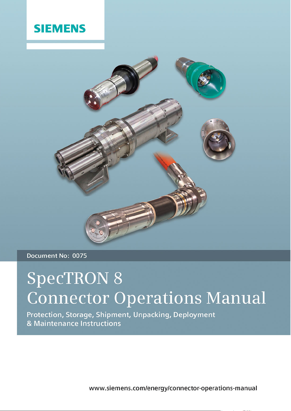
Thank you for purchasing a Siemens Subsea SpecTRON 8 product. The information that
follows is an overview of the protection, storage, shipment, unpacking, deployment and
maintenance instructions for Siemens Subsea SpecTRON products.
Siemens Subsea recommends the termination of all equipment must only be undertaken
by suitably trained and qualified personnel.
Revision Control:
Section 2.3.2 - Details of AquaTRON 50 added to Operations Manual.
Section 2.3.3 - Details of internal cables added
Section 4 - Minimum Bend Radius of AquaTRON 50 added to document.
Section 7.4 - Figure 14 updated to show connectors with locking mechanism.
Section 7.6 - Figure 17 updated to show connectors with locking mechanism.
Section 7.6 - Figures 18 & 19 added showing 3 finger jaw for fishtail ROV handle
Section 8.3 & 8.4 - Mate & De-mate procedures added for ROV connectors with locking
mechanism.
Section 8.7 – Emergency Demechanism.
Section 8 - Figures 23, 24, 25, 26 & 27 added
Section 9 - Manual Mate & Demechanism.
Section 9 - Figures 30 & 31 added
Section 5.1 - Note added for lifting precaution over coating components.
Unrestricted
3 Document is uncontrolled outside of document management system
© Siemens plc. 2019 All Rights Reserved.
Page ii of iii
Page 3
SIEMENS SpecTRON 8
MANUAL
Doc No:
0075
Rev No:
8
Category:
Technical
Created By:
W.Barrett
9
J. Keith
D. Church
18/10/2017
Document tracked changes removed.
10
T. Archer
D. Church
23/02/2018
Correcting Figure Numbers, Adding optional packaging section
11
D. Brown
S. Fitton
23/01/2019
Section 1 – Note added to include the Dual Penetrator as an included connector type.
Assembly.
12
S.Hargreaves
M.Earnshaw
04/07/2019
Section 3.3.1 - Updated Hose weight to match current calculated weight
Section 8.6 - Added in weight restrictions for EFLs
13
S.Hargreaves
M.Earnshaw
12/09/2019
Section 5.1 - Figure 8 updated to include central slinging position on the Dual Penetrator
Document header revision corrected.
Section 5.1 – Figure 8 added for the recommended lifting positions for the Dual Penetrator
Assembly and added note about inboard termination.
Updated whole document to latest Siemens template format.
Section 3.3.3 – Added cable OD, MBR, Weight in Air and Weight in Water for both 35mm
and 4mm
Created Section 3.3.4 to include test connector cable information.
Changed Rev 12 Sections 10.2, 10.3, 10.5 and 10.6 into sub sections of 10.1 and 10.2 as
10.1 and 10.2 didn’t have any content underneath their titles.
Created Section 11 to describe connection points etc. for test connectors.
Section 5.1 Figures 4, 5, 6 & 7 – Corrected positions of arrows.
Document Control Page – Removed Tronic reference and replaced with Siemens.
2
.
PRODUCTS – OPERATIONS
2
Unrestricted
3 Document is uncontrolled outside of document management system
© Siemens plc. 2019 All Rights Reserved.
Page iii of iii
Page 4

SIEMENS SpecTRON 8
MANUAL
Doc No:
0075
Rev No:
8
Category:
Technical
Created By:
W.Barrett
PRODUCTS – OPERATIONS
Contents
1. SCOPE ............................................................................................................................................. 2
2. HEALTH & SAFETY ........................................................................................................................ 2
3. SPECIFICATION .............................................................................................................................. 3
3.1 ELECTRICAL ............................................................................................................................... 3
3.2 ENVIRONMENTAL ...................................................................................................................... 3
3.3 HOSE & CABLE ........................................................................................................................... 3
4. MARKING ........................................................................................................................................ 5
5. PROTECTION, HANDLING AND SHIPMENT ................................................................................. 6
5.1 LIFTING OF JUMPERS & CONNECTORS ................................................................................. 7
6. UNPACKING .................................................................................................................................. 11
6.1 PROTECTIVE CAPS ................................................................................................................. 11
7. STORAGE ...................................................................................................................................... 15
8. DEPLOYMENT & MAINTENANCE ................................................................................................ 15
8.1 GENERAL .................................................................................................................................. 15
8.2 PROTECTION OF RECEPTACLE CONTACT PINS ................................................................. 16
8.3 OVER CURRENT CAPACITY.................................................................................................... 16
8.4 REMOVAL OF MARINE GROWTH AND CALCAREOUS DEPOSITS ...................................... 17
8.5 STAB PLATE CONNECTORS ................................................................................................... 19
8.6 ROV CONNECTORS ................................................................................................................. 20
9. ROV MATE / DE-MATE PROCEDUREs ....................................................................................... 23
9.1 ROV MATING PROCEDURE..................................................................................................... 23
9.2 ALIGNMENT AND MATING PROCEDURE – CONNECTORS WITHOUT LOCKING
MECHANISM ............................................................................................................................. 23
9.3 ALIGNMENT AND MATING PROCEDURE – CONNECTORS WITH LOCKING
MECHANISM ............................................................................................................................. 27
9.4 ROV DE-MATING PROCEDURE .............................................................................................. 29
9.5 DE-MATING PROCEDURE - CONNECTORS WITHOUT LOCKING MECHANISM ................. 29
9.6 DE-MATING PROCEDURE - CONNECTORS WITH LOCKING MECHANISM ........................ 29
9.7 EMERGENCY DE-MATE PROCEDURE – CONNECTORS WITH LOCKING
MECHANISM ONLY .................................................................................................................. 31
10. MANUAL MATE/ DE-MATE PROCEDUREs ............................................................................ 32
10.1 MANUAL MATING PROCEDURE ......................................................................................... 32
10.2 MANUAL DE-MATING PROCEDURE ................................................................................... 34
11. TOPSIDE TEST CONNECTORS ............................................................................................... 36
12. INSTALLATION ......................................................................................................................... 37
12.1 CONNECTOR & PENETRATOR INSTALLATION ................................................................ 37
12.2 HOSE ROUTING AND SUPPORT ........................................................................................ 37
13. INFORMATION & NOTES / HEALTH & SAFETY FEEDBACK ................................................ 38
Document is uncontrolled outside of document management system
Unrestricted
© Siemens plc. 2019 All Rights Reserved.
Page 1 of 38
Page 5
SIEMENS SpecTRON 8
MANUAL
Doc No:
0075
Rev No:
8
Category:
Technical
Created By:
W.Barrett
Note: All receptacle’s (male pins) must be mated to its correct mating half before it
is energised (this includes the correct Test, Dummy and Wet Mate Pair).
PRODUCTS – OPERATIONS
1. SCOPE
This procedure includes information on the following connector types:
• SpecTRON 8 ROV Plugs
• SpecTRON 8 ROV Receptacles
• SpecTRON 8 Penetrators
• SpecTRON 8 Dual Penetrator
• SpecTRON 8 Tree Cap Plug (TCP)
• SpecTRON 8 Tubing Hanger Receptacle (THR)
• SpecTRON 8 ROV Dummy Connectors (Plugs & Receptacles)
• SpecTRON 8 ROV Parking Receptacle
2. HEALTH & SAFETY
• Manual Handling, Lifting and Carrying are known to be the largest contributors to
occupational ill-health.
• Ensure that mechanical handling aids are used whenever possible to avoid manual
handling.
• Where manual handling is considered appropriate for the task safe lifting guidelines
must be followed, e.g. adopt correct posture, consider team lifting, employ safe
lifting technique, etc.
• Only competent persons are permitted to perform tasks without supervision, if in
doubt ask.
• Good Housekeeping avoids Slips Trips and Falls, keep your area clean and tidy.
• It is the operator’s responsibility to comply with current Company & regional health
and safety legislation.
• Caution shall be exercised during assembly to ensure that fittings and hydraulic /
pneumatic equipment are properly installed.
In the event of a safety incident or any safety improvement suggestions, please contact
the Health & Safety Department at prodsafe.gb@siemens.com and/or complete and return
the punch list in section 13.
Unrestricted
Document is uncontrolled outside of document management system
© Siemens plc. 2019 All Rights Reserved.
Page 2 of 38
Page 6

SIEMENS SpecTRON 8
MANUAL
Doc No:
0075
Rev No:
8
Category:
Technical
Created By:
W.Barrett
PRODUCTS – OPERATIONS
3. SPECIFICATION
The following is a basic specification for SpecTRON 8 connectors. Actual product may
vary. Please refer to product specific data sheet or Project specific Design Input Document
for more detailed information.
3.1 ELECTRICAL
Rated Voltage: 5/8.7(10) kV
Rated Frequency: 1-200Hz
Rated Current: 335 A (@25°C, 50Hz)
220 A (@110°C, 50Hz THR only)
220 A (@90°C, 50Hz TCP only)
3.2 ENVIRONMENTAL
Storage Temperature: -30°C to + 60°C
Handling Temperature: -25°C to +70°C
Operating temperature: +4°C to + 40°C ROV
+4°C to + 110°C THR
+4°C to + 90°C TCP
Max Deployment Rate: 20bar / min
Max Water Depth: 3000 m
3.3 HOSE & CABLE
3.3.1 AQUATRON 200 (2” BORE)
Outside Diameter: 64.4 mm Nom
Outside Pressurised Diameter: 66 mm Nom
Minimum Bend Radius: 375 mm
Weight in Air (Inc cable and oil): 4.8 kg/m
Weight in Water (Inc cable and oil): 1.45 kg/m
3.3.2 AQUATRON 50 (1/2” BORE)
Outside Diameter: 25.2 ± 0.6 mm
Minimum Bend Radius: 125 mm
Weight in Air (Inc cable and oil): 0.66 kg/m
Weight in Water (Inc cable and oil): 0.14 kg/m
Document is uncontrolled outside of document management system
Unrestricted
© Siemens plc. 2019 All Rights Reserved.
Page 3 of 38
Page 7
SIEMENS SpecTRON 8
MANUAL
Doc No:
0075
Rev No:
8
Category:
Technical
Created By:
W.Barrett
Note: When performing terminations (e.g. inboard) involving exposed unscreened
cable (i.e. no hose), consideration should be given to proximity to “sharp/point”
earths.
PRODUCTS – OPERATIONS
3.3.3 CABLE SPECIFICATION (EXCLUDING THR + UMBILICAL RECEPTACLES)
Cable for Phase: 35mm2 Flexible Cable (Unscreened)
Outside Diameter: 18.10 ± 0.40 mm
Minimum Bend Radius: 110 mm
Weight in Air: 0.55 kg/m
Weight in Water: 0.29 kg/m
Cable for Signal Return: 4mm2 Flexible Cable (Unscreened)
Outside Diameter: 8.95 ± 0.20 mm
Minimum Bend Radius: 55 mm
Weight in Air: 0.11 kg/m
Weight in Water: 0.04 kg/m
3.3.4 TEST CONNECTOR CABLE SPECIFICATION
Cable for Phase: 35mm2 Flexible Cable (Screened)
Outside Diameter: 24.5 mm
Minimum Bend Radius: 125 mm
Weight in Air: 1.04 kg/m
Weight in Water: 0.56 kg/m
Unrestricted
Document is uncontrolled outside of document management system
© Siemens plc. 2019 All Rights Reserved.
Page 4 of 38
Page 8
SIEMENS SpecTRON 8
MANUAL
Doc No:
0075
Rev No:
8
Category:
Technical
Created By:
W.Barrett
Marking of Siemens Subsea Part
No and Serial No for individual
Marking of Siemens
PRODUCTS – OPERATIONS
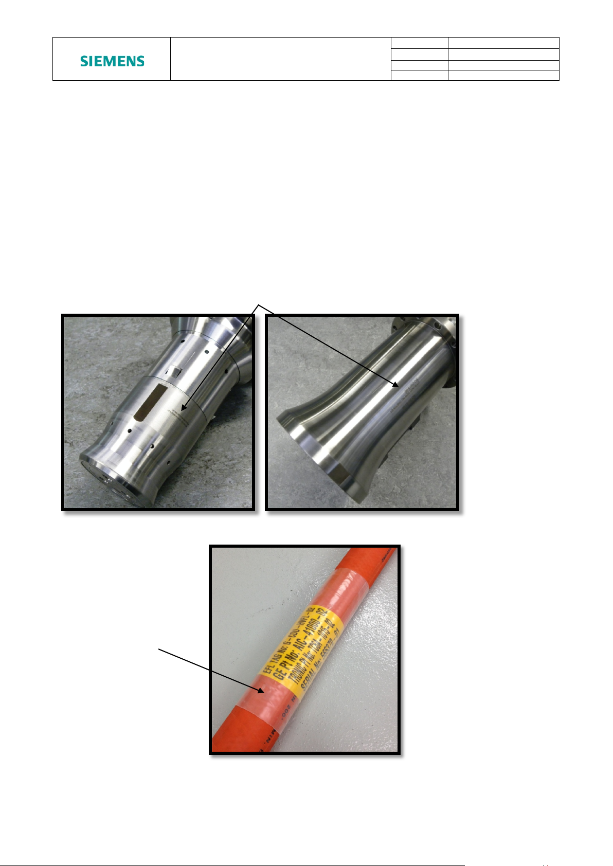
4. MARKING
Siemens Subsea Connectors and Penetrators are marked with the Siemens Subsea part
number and unique serial number. Marking locations are typically on the Plug Nose and
Receptacle Shroud for Wet Mate Connectors and on the Flange of Penetrators. Figure 1
shows the typical marking locations for a Plug and Receptacle. Marking is typically by
laser etching.
Harnesses are also marked with the Siemens Subsea part number and unique serial
number for the harness as shown in Figure 2. Client and project specific information is also
usually added to these labels. Labels are typically black text on a yellow background
underneath clear heat shrink. Typically, labels are located at each end of the harness and
also centrally.
Subsea Part No, Serial
No and client
information on
Document is uncontrolled outside of document management system
Figure 1 – Marking of Connectors
Figure 2 – Marking of Hoses
Unrestricted
© Siemens plc. 2019 All Rights Reserved.
Page 5 of 38
Page 9
SIEMENS SpecTRON 8
MANUAL
Doc No:
0075
Rev No:
8
Category:
Technical
Created By:
W.Barrett
Note: Maximum storage temperature takes into account solar gain. Skin
with similar properties must be used to ensure maximum storage temperature is
not exceeded.
PRODUCTS – OPERATIONS
5. PROTECTION, HANDLING AND SHIPMENT
Siemens Subsea electrical connectors are manufactured primarily from materials such as
316L stainless steel (UNS S31603), and Super Duplex stainless steel (UNS S32550).
Stainless steel 316L (UNS S31603) connectors and penetrators must be connected to a
CP (Cathodic Protection) system at all times in order to withstand harsh saliferous
environments. Super Duplex stainless steel (UNS S32550 / UNS S32760) ROV
connectors may be isolated from the CP system to reduce the possibility of hydrogen
embrittlement and calcareous deposits. ROV Connectors are designed with isolation
bushes and discs in order to isolate them from the structure as standard. Tree Cap Plugs,
Tubing Hanger Receptacles and Penetrators cannot be isolated from the structure and
thus may be connected to the CP system.
The connector insert and exposed parts are susceptible to mechanical damage if not
adequately protected. Dust caps or Protective caps are fitted to all Siemens Subsea
connectors before transport. Caps are recommended to remain in place until connectors
are deployed subsea.
The connectors can be shipped singularly or in multiples. Care should be taken to protect
the connector with bubble wrap or similar wrapping materials to avoid surface damage
during transit. If large numbers are shipped in one consignment a suitably reinforced box
will be necessary to withstand the weight. Protection caps must be fitted at all times
during transport.
temperature must not exceed 700C. Suitable protection i.e. a tarpaulin or material
If storage is carried out in saline conditions, e.g. on a ship’s deck or hold, then full dummy
connectors should be used.
Bulkhead type connectors with exposed tailing wires should be packed and shipped in a
suitably sized box to allow adequate space for the tailing wires without bending or kinking.
If the connectors are assembled onto hoses these must be suitably coiled and secured
with tape to prevent uncoiling during transit. The following bend radii are recommended for
storage/transport of hose.
• AquaTRON 2” NB (AquaTRON 200) - Minimum bend radii - 375mm
• AquaTRON 0.5” NB (AquaTRON 50) - Minimum bend radii - 125mm
Connectors are designed to withstand vibration that occurs during transportation and to
withstand being dropped from a height of 1m whilst in packaging.
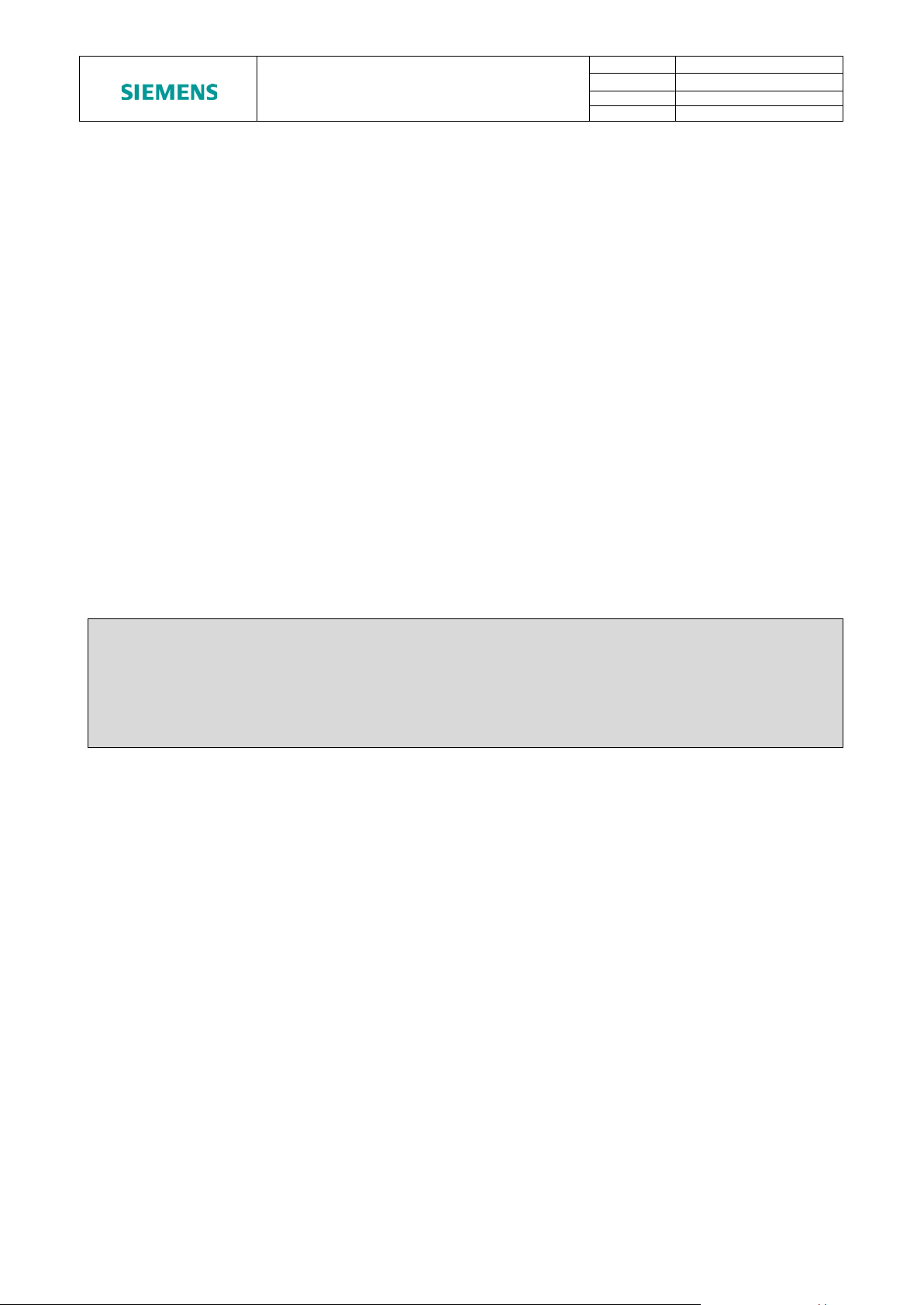
Figure 3A shows how a SpecTRON 8 harness is packaged. The connectors on either end
of the harness have a transportation cap fitted and are surrounded in bubble wrap. The
base of the shipping crate is lined with protective packaging and the harness is positioned
so that the hose can be coiled without kinking. Any loose items are placed in a box inside
the crate. Protective packaging is then placed on top of the harness and secured in place
with a wooden baton, before the lid of the crate is screwed down.
Document is uncontrolled outside of document management system
© Siemens plc. 2019 All Rights Reserved.
Unrestricted
Page 6 of 38
Page 10
SIEMENS SpecTRON 8
MANUAL
Doc No:
0075
Rev No:
8
Category:
Technical
Created By:
W.Barrett
Note: Ensure that all coated components are handled with care during lifting to
avoid damaging the coating.
PRODUCTS – OPERATIONS
Figure 3A – Standard Packaging.
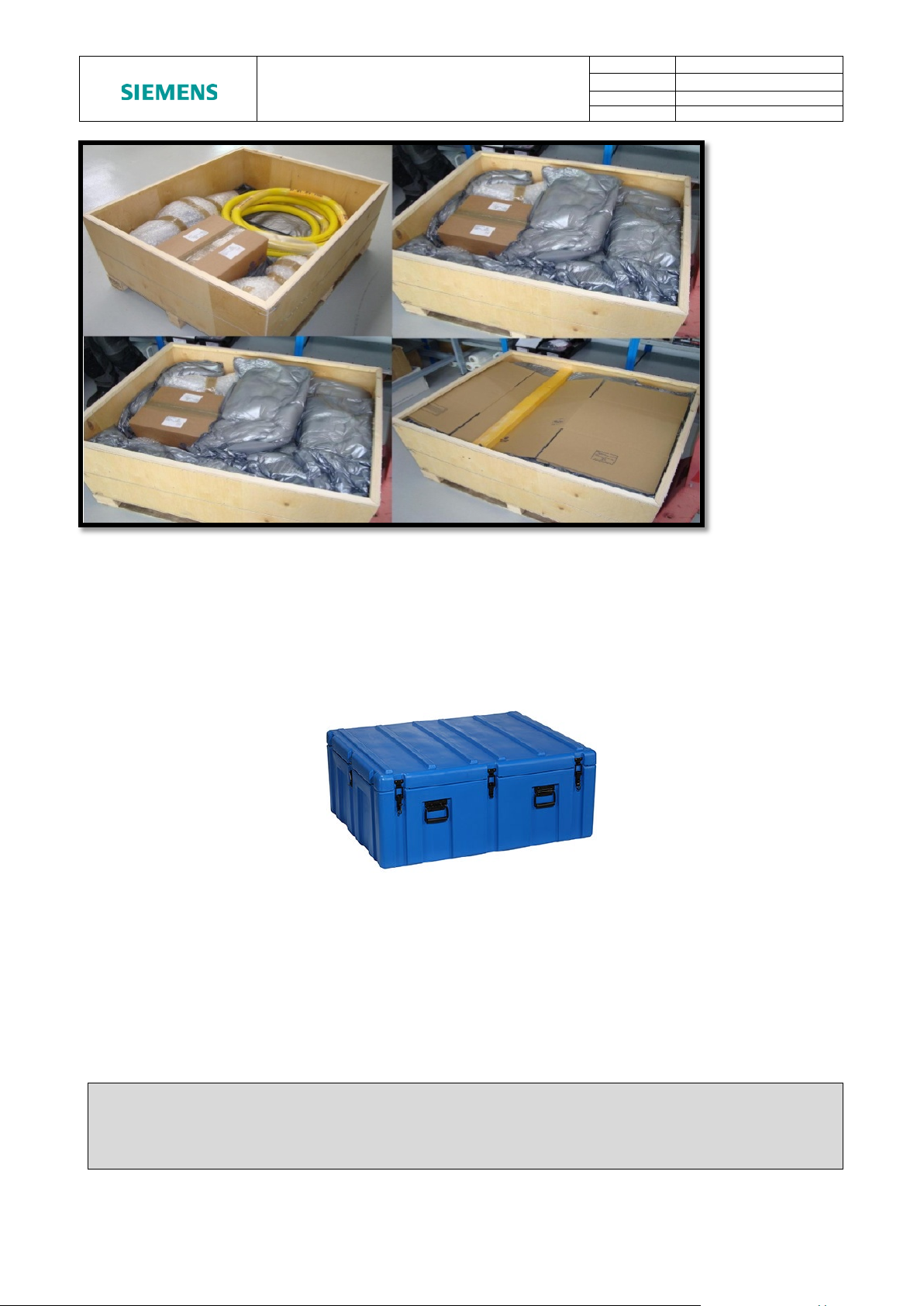
Figure 3B shows a different type of optionally purchased packaging the harness could be
supplied in. This crate is manufactured from polyethylene plastic and is dust, oil, chemical
and water resistant. The connectors on either end will have a transportation cap and will sit
within a foam insert which will be sized to the connector. Any loose items will be placed in
a box inside the crate.
Figure 3B – Optional Packaging
5.1 LIFTING OF JUMPERS & CONNECTORS
SpecTRON 8 harnesses typically weigh in excess of 30 kg and hence should not be
manually handled. Refer to the specific harness drawing for weight and length details. The
connectors can be safely slung around the locations shown in, Figure 4 , Figure 5, Figure
6 and Figure 7. The centre of gravity for the Connector or Penetrator is usually marked on
the outline drawing (supplied in documentation pack) but must be verified at low level
before commencing any lift.
Unrestricted
Document is uncontrolled outside of document management system
© Siemens plc. 2019 All Rights Reserved.
Page 7 of 38
Page 11
SIEMENS SpecTRON 8
MANUAL
Doc No:
0075
Rev No:
8
Category:
Technical
Created By:
W.Barrett
Sling around each side of
the Receptacle Flange
Do not sling around
release protective cap
Sling around Plug
Do not sling around
locking mechanism
PRODUCTS – OPERATIONS
ROV Receptacle
Rear Shell between
handlebars
Figure 4 - Recommended lift position - ROV Receptacle
handle as this may
the outside of the
connector handle as
this may damage the
ROV Plug (With / Without locking mechanism)
Figure 5 - Recommended lift positions - ROV Plug
Unrestricted
Document is uncontrolled outside of document management system
© Siemens plc. 2019 All Rights Reserved.
Page 8 of 38
Page 12
SIEMENS SpecTRON 8
MANUAL
Doc No:
0075
Rev No:
8
Category:
Technical
Created By:
W.Barrett
Sling around
Penetrator Rear Shell
Sling each
Protective Cap
PRODUCTS – OPERATIONS
Dummy, or parking connectors weigh less than 20 kg and can be lifted by hand, however correct
lifting practice should be observed at all times.
Figure 6 - Tree Cap Penetrator / Plug
Side of
Figure 7 - Tree Cap Penetrator / Plug
Unrestricted
Document is uncontrolled outside of document management system
© Siemens plc. 2019 All Rights Reserved.
Page 9 of 38
Page 13
SIEMENS SpecTRON 8
MANUAL
Doc No:
0075
Rev No:
8
Category:
Technical
Created By:
W.Barrett
Important Note: Connectors / Penetrators should NEVER be lifted by the hose or
in loss of continuity.
Sling around Dual Penetrator
the Dual Penetrator body as
PRODUCTS – OPERATIONS
body, or each side as close to
Figure 8 - Recommended Lift Positions - Dual Penetrator
For dual penetrator inboard termination details refer to project documentation.
cable, as this places unnecessary strain on the connector internals and may result
Connector / Penetrator. The maximum recommended length of hose which can be
unsupported during a lifting operation is 5 meters.
Protective caps should remain on wherever possible during lifting operations to minimise
the risk of damage to connector sealing or electrical components.
Unrestricted
Document is uncontrolled outside of document management system
© Siemens plc. 2019 All Rights Reserved.
Page 10 of 38
Page 14

SIEMENS SpecTRON 8
MANUAL
Doc No:
0075
Rev No:
8
Category:
Technical
Created By:
W.Barrett
Pull on ROV
Grip cap by
PRODUCTS – OPERATIONS
6. UNPACKING
Remove wrapping material taking care to inspect for any surface damage or items that
may have become separated from the connector, such as ‘O' seals. Do not use a knife to
cut the wrapping material, as this may cause damage to any elastomeric parts of the
connector. Do not remove protection caps until connectors are ready for installation. On
removal do not allow the hoses to drag over the edges of the packing crate.
6.1 PROTECTIVE CAPS
All SpecTRON 8 Connectors/Penetrators come supplied with a protective cap. These can
either be dust caps or protective caps. Dust caps (typically yellow in colour) can be simply
removed by twisting or pulling them off. Protective caps (typically black in colour) can be
removed as detailed below.
6.1.1 ROV PLUG CAP
The ROV Plug cap is latched onto the Plug connector via the connector latching
mechanism. In order to remove the cap, it is recommended that the operator stand the
Plug vertically on the cap, stand on the flange of the cap and pull on the ROV handle of
the Plug connector. This will disengage the latching mechanism of the Plug. Do not try to
pull the cap directly off the plug as this may damage the latching mechanism of the Plug.
Use the same method when engaging and disengaging the ROV plug cap on the Plug
connectors with the locking mechanism.
Handle
Refitting the Plug cap can be done by simply pushing the cap back onto the nose of the
plug until the latching mechanism of the plug engages.
standing on
flange
Figure 9 - ROV Plug Cap
Unrestricted
Document is uncontrolled outside of document management system
© Siemens plc. 2019 All Rights Reserved.
Page 11 of 38
Page 15

SIEMENS SpecTRON 8
MANUAL
Doc No:
0075
Rev No:
8
Category:
Technical
Created By:
W.Barrett
Remove the
Cap End
Pull the keyed
Pull on
remove
PRODUCTS – OPERATIONS
6.1.2 ROV RECEPTACLE CAP
The ROV Receptacle Cap can be removed by pulling on the cap. Refitting the Receptacle
cap can be done by simply pushing the cap back onto the Receptacle shroud.
Cap to
Figure 10 - ROV Receptacle Cap
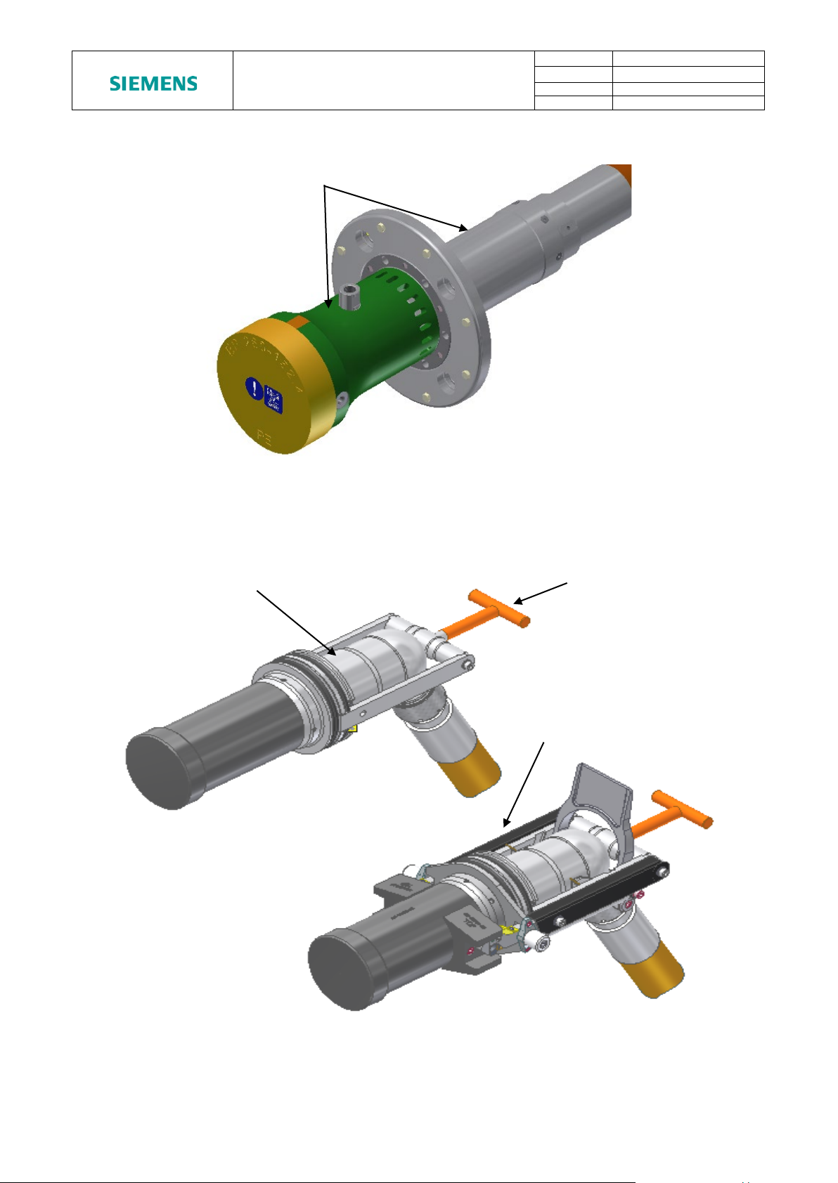
6.1.3 TREE CAP PENETRATOR CAP – VERSION 1
Penetrator caps would usually be removed by Siemens Subsea site engineers during the
termination of the Penetrator to the module. It is recommended that only trained personnel
remove Penetrator caps though details are provided here for information only. The Tree
Cap Penetrator version 1 consists of modular parts to protect the entire length of the
connector. Carefully position the Plug & Penetrator on a suitable bench and remove the
protective cap taking care not to bend the compliant gland between plug and penetrator.
Cap End with a
dowel pin.
Figure 11 - Tree Cap Penetrator / Plug Removal of Keyed Cap
Unrestricted
Document is uncontrolled outside of document management system
© Siemens plc. 2019 All Rights Reserved.
Page 12 of 38
Page 16

SIEMENS SpecTRON 8
MANUAL
Doc No:
0075
Rev No:
8
Category:
Technical
Created By:
W.Barrett
Pull the
Unscrew this end
8kV Penetrator.
Remove
Sleeve
Remove
Sleeve
PRODUCTS – OPERATIONS
section attached to
whole cap
to remove
Figure 12 - Tree Cap Penetrator / Plug Protective Cap Removal
Protective Split
Protective Split
Figure 13 - Tree Cap Penetrator / Plug Split Sleeve Removal
Refitting the Penetrator cap is a reversal of the removal procedure.
Unrestricted
Document is uncontrolled outside of document management system
© Siemens plc. 2019 All Rights Reserved.
Page 13 of 38
Page 17

SIEMENS SpecTRON 8
MANUAL
Doc No:
0075
Rev No:
8
Category:
Technical
Created By:
W.Barrett
Pull cap to
remove
Unscrew fasteners
Cap
PRODUCTS – OPERATIONS
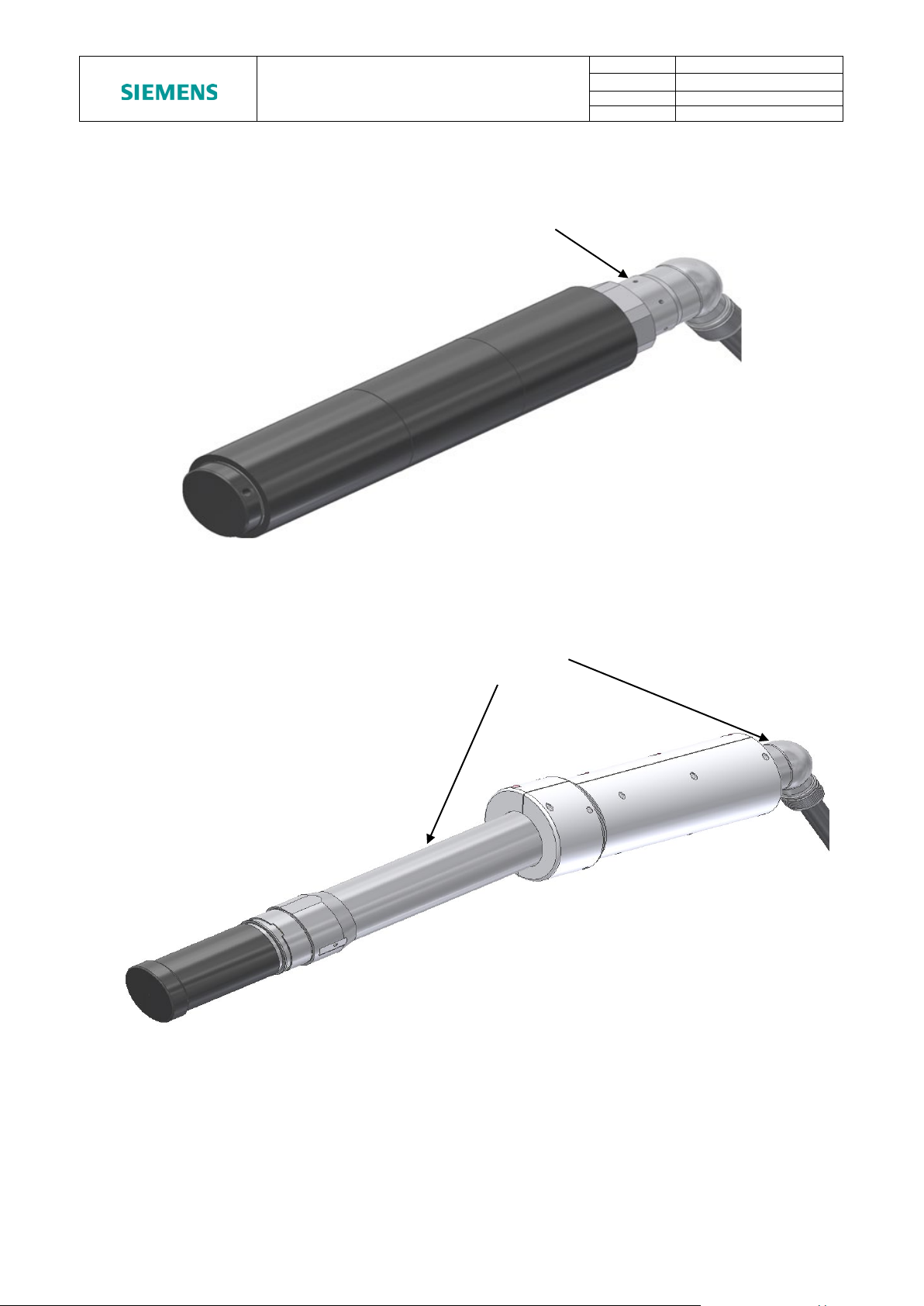
6.1.4 TREE CAP PENETRATOR CAP – VERSION 2
Penetrator caps would usually be removed by Siemens Subsea site engineers during the
termination of the Penetrator to the module. It is recommended that only trained personnel
remove Penetrator caps though details are provided here for information only. The Tree
Cap Penetrator version 2 consists of split halves to protect the compliant gland. Carefully
position the Plug & Penetrator on a suitable bench and remove the protective cap taking
care not to bend the compliant gland between plug and penetrator.
and Remove Split
Figure 14 - ROV Receptacle - Penetrator - Tree Cap Plug Jumper
Unrestricted
Document is uncontrolled outside of document management system
© Siemens plc. 2019 All Rights Reserved.
Page 14 of 38
Page 18

SIEMENS SpecTRON 8
MANUAL
Doc No:
0075
Rev No:
8
Category:
Technical
Created By:
W.Barrett
Note: It is important to isolate and earth prior to disconnect in order to remove
pins once the plug is removed.
PRODUCTS – OPERATIONS
7. STORAGE
The connectors must be stored in a clean dry area and be protected by bubble wrap or
similar. Suitable protection caps must be fitted and the storage temperature should be
between -30°C and 60°C (Project Specific Connectors storage Temperature may vary).
Humidity of the store room should be below 75%. Very moist or very dry conditions should
be avoided. The Plug connector and hoses should be protected from strong sunlight and
strong artificial light with a high ultra violet content. The connectors should not be allowed
to come into contact with solvents, oil, greases or any other semi-solid materials. If
glanded connectors are to be stored bolted into their interfaces prior to cable termination,
then ensure the cable entry point into the gland is covered to prevent water ingress.
8. DEPLOYMENT & MAINTENANCE
The following section details deployment and maintenance instructions for SpecTRON 8
connectors & hose.
All information contained within this section is generic. Where customer or project-specific
information is required, please refer to the relevant project specification or scope of supply.
any stray charges in the system. If left, this can induce corrosion on the exposed
8.1 GENERAL
The SpecTRON 8 range of Power connectors has been developed for long term reliable
high power system applications associated with offshore installations. The underwater
mateable capacity of these connectors is achieved using pressure compensated electrical
inserts employing the CE principle.
Connectors are usually supplied with protective caps. The protective caps must be
removed prior to mating the connectors. Refer to section 6.1 for instructions for removal of
protective caps.
All mild steel sealing interfaces shall be inlayed with Inconel 625, or similar, where no
additional protection (e.g. CP, Paint etc.) can be provided. This is to prevent localised
pitting of the interface.
If the connectors are to be left unmated, in seawater, for any length of time dummy
connectors must be used to protect the pin contacts in the receptacle connectors. Over
exposure will increase the risk of corrosion damage or marine growth on the contact
surfaces of the receptacle contact pins. This could lead to damage to the seals and
insulation within the socket contacts.
Unrestricted
Document is uncontrolled outside of document management system
© Siemens plc. 2019 All Rights Reserved.
Page 15 of 38
Page 19

SIEMENS SpecTRON 8
MANUAL
Doc No:
0075
Rev No:
8
Category:
Technical
Created By:
W.Barrett
Important Note: 60 days* is the maximum cumulative allowable exposure of
the connector. This only applies with power off.
Important Note: Under NO circumstances must connectors be demated whilst live.
Neither should connectors be partially mated with power applied.
Important Note: NO part of the connectors should be dismantled prior to or during
deployment, apart from the removal of protective caps, since there are no user
serviceable parts inside.
PRODUCTS – OPERATIONS
Plug connectors may be left unmated, in seawater, for an indefinite period of time.
However it is recommended that the Plug connectors are mated into a Parking Receptacle
during this time in order to protect the socket contacts and latching mechanism.
It is good practice to always fit the protective cap when a connector is unmated topside
prior to deployment to provide mechanical protection.
unprotected contact pins (receptacle connectors only) to seawater over the life of
*60 days applicable to Receptacle connectors supplied from January 2013. Connectors supplied before this
date may be limited to 30 days. Contact Siemens Subsea for further information on specific connector serial
numbers.
The appropriate test connector must always be used to make electrical contact during
testing. UNDER NO CIRCUMSTANCES should a foreign object (such as a screwdriver,
test probe, or crocodile clip) be used as a test connection as this could damage the seals
and insulation. Such actions will invalidate the warranty of the connector.
Guide pins must never be removed from test connectors as this can lead to damage and
will invalidate the connector warranty.
Refer to project specific data sheets and scope of supply drawings for performance
specifications and detailed deployment instructions.
8.2 PROTECTION OF RECEPTACLE CONTACT PINS
Under no circumstances must the contact pins in the receptacle connector be exposed to
seawater with power on. If this situation does occur the contact surfaces of the pins will
very rapidly degrade by electrolytic action. If these damaged pins are subsequently mated
into a socket insert there is a very high risk of damage to the insulation and seals within
the plug connector.
8.3 OVER CURRENT CAPACITY
Over current capacity varies for each product. Please refer to the product datasheet.
Unrestricted
Document is uncontrolled outside of document management system
© Siemens plc. 2019 All Rights Reserved.
Page 16 of 38
Page 20

SIEMENS SpecTRON 8
MANUAL
Doc No:
0075
Rev No:
8
Category:
Technical
Created By:
W.Barrett
PRODUCTS – OPERATIONS
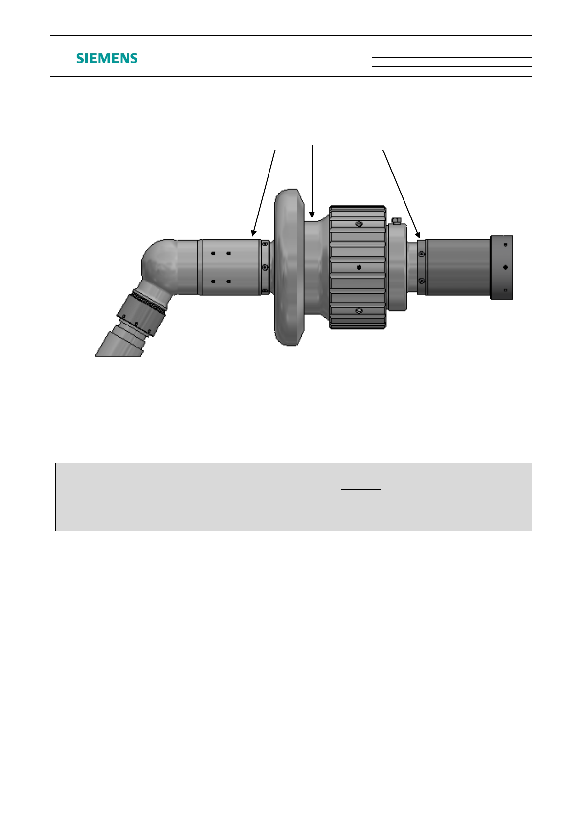
8.4 REMOVAL OF MARINE GROWTH AND CALCAREOUS DEPOSITS
To remove calcite growth from Siemens Subsea connectors, a solution of 50% Citric Acid
is recommended. All Seawater exposed elastomeric materials in Siemens Subsea
connectors have been fully tested against 50% Citric Acid and are compatible for duration
of 1 hour. In addition, the thermoplastic materials have good resistance to Citric Acid.
It is recommended the solution is introduced through the flushing port adaptor (as per
Figure 15) to provide maximum saturation within the Plug/Receptacle annulus. Others
cavities on the receptacle shroud can be utilised to introduce the solution dependant on
access capability.
Other acid cleaners, such as 50% Acetic Acid, should not be used as they may cause
deterioration of the elastomeric materials.
Chiselling and abrasive methods are not recommended. Wiping with a soft, clean cloth is
acceptable providing care is taken inside the Receptacle shroud to avoid imparting a
bending load on the power pin/s. Use of water jetting for the removal of sand/silt is
acceptable given the following limitations:
• All forms of water jet cleaning of connectors in air must be avoided. The likelihood
of damage to connectors is great, given the high localised impact velocities of the
water jet.
• Submerged water jet cleaning of connectors is acceptable, providing the critical
areas identified in Figure 14 & Figure 15 are avoided. Particularly, the jet should
not be directed at the Plug front face / shuttle pins as this could result in a risk of
water being forced through the primary seals and/or front seal. Remaining areas
indicated below are suitable for submerged water jet cleaning.
Document is uncontrolled outside of document management system
Unrestricted
© Siemens plc. 2019 All Rights Reserved.
Page 17 of 38
Page 21

SIEMENS SpecTRON 8
MANUAL
Doc No:
0075
Rev No:
8
Category:
Technical
Created By:
W.Barrett
Flushing Port
PRODUCTS – OPERATIONS
Adaptor
Figure 15 - Connector Power Washing Precautions
Figure 16 - Connector Power Washing Precautions
Unrestricted
Document is uncontrolled outside of document management system
© Siemens plc. 2019 All Rights Reserved.
Page 18 of 38
Page 22

SIEMENS SpecTRON 8
MANUAL
Doc No:
0075
Rev No:
8
Category:
Technical
Created By:
W.Barrett
PRODUCTS – OPERATIONS
8.5 STAB PLATE CONNECTORS
Compliance
One half of a stab mate connector pair must be allowed to float so that misalignment
tolerances can be accommodated.
Mate/De-Mate Speed
The connectors have been designed to operate across a wide range of mate / de-mate
speeds with POWER OFF. There is no practical limit to the speed at which the connectors
maybe mated or de-mated, however as a guide:
Mating speed should not exceed 1 m/s.
De-mating speed should not exceed 5 m/s
Pre-Mating Checks
Before mating, the receptacle connector should be checked for debris. The connectors
have been designed to accommodate sand and silt contamination; however large pieces
of debris should be removed using a water jet.
Partial Disconnection
Partial disconnection with the contact pin remaining between the primary and secondary
diaphragms is not recommended. In this condition the level of insulation between the
contact pin and socket contact is reduced and the connector is relying on the primary seals
within the plug. There is also an increased risk of insulation break down at increased
voltages.
Interrupted Connection
Interrupted connection (i.e. Partial mate to full de-mate) can be carried out without any
adverse affect to connectors, as long as the power is off.
Cathodic Protection:
Stainless steel 316L (UNS S31603) connectors must be connected to the CP (Cathodic
Protection) system at all times. Super Duplex stainless steel (UNS S32550 / UNS S32760)
connectors may be isolated from the CP system through the design of the structure to
which they are connected to reduce the possibility of hydrogen embrittlement and
calcareous deposits. However, it should be noted that Tree Cap Plugs, Tubing Hanger
Receptacles and Penetrators cannot be isolated from the structure as they do not utilise
isolation discs and bushes due to their mechanical and pressure retaining requirements.
Document is uncontrolled outside of document management system
Unrestricted
© Siemens plc. 2019 All Rights Reserved.
Page 19 of 38
Page 23

SIEMENS SpecTRON 8
MANUAL
Doc No:
0075
Rev No:
8
Category:
Technical
Created By:
W.Barrett
PRODUCTS – OPERATIONS
8.6 ROV CONNECTORS
ROV Manipulator
SpecTRON 8 connectors are fitted with either an ISO 13628 T-bar handle or an ISO 13628
Fish Tail Handle.
ROV EFLs under or equal to 30m require no buoyancy aids for subsea deployment.
ROV EFLs over 30m require buoyancy aids which must be placed at reasonable positions
along the harness and are suitable to support 1.45kg (See 3.3.1) per metre length in
excess of 30m e.g. a 50m EFL requires buoyancy aids to cover 20*1.45 = 29kg worth of
additional hose weight in water.
T Bar Handle
T-bar handle connectors must be manipulated using a Parallel Jaw ROV manipulator
similar to that shown in Figure 17.
Figure 17 - Recommended ROV Manipulator Jaw for T Bar Handle
The T bar should be held by the crossbar of the T as shown in Figure 18 and not by the
shaft. If the T bar is held incorrectly there is a risk that the latch mechanism of the
connector will not engage correctly.
Unrestricted
Document is uncontrolled outside of document management system
© Siemens plc. 2019 All Rights Reserved.
Page 20 of 38
Page 24

SIEMENS SpecTRON 8
MANUAL
Doc No:
0075
Rev No:
8
Category:
Technical
Created By:
W.Barrett
PRODUCTS – OPERATIONS
Document is uncontrolled outside of document management system
Figure 18 - ROV Connector Handling
Unrestricted
© Siemens plc. 2019 All Rights Reserved.
Page 21 of 38
Page 25

SIEMENS SpecTRON 8
MANUAL
Doc No:
0075
Rev No:
8
Category:
Technical
Created By:
W.Barrett
PRODUCTS – OPERATIONS
Fish Tail Handle
Fish Tail Handle connectors must be manipulated using a 3-finger ROV manipulator jaw
similar to that shown in Figure 19. The handle should be held in the ROV jaw as shown in
Figure 20.
Figure 19 - Recommended ROV Manipulator Jaw for Fishtail Handle
Document is uncontrolled outside of document management system
Figure 20 - ROV Connector Handling
Unrestricted
© Siemens plc. 2019 All Rights Reserved.
Page 22 of 38
Page 26

SIEMENS SpecTRON 8
MANUAL
Doc No:
0075
Rev No:
8
Category:
Technical
Created By:
W.Barrett
Alignment Indicators
Physical Key / Keyway
PRODUCTS – OPERATIONS
9. ROV MATE / DE-MATE PROCEDURES
9.1 ROV MATING PROCEDURE Pre Mating Checks
Before mating, the receptacle shroud should be checked for debris. The connectors have
been designed to accommodate sand and silt contamination. However, large pieces of
debris should be removed.
9.2 ALIGNMENT AND MATING PROCEDURE – CONNECTORS WITHOUT LOCKING MECHANISM
• The connectors have been designed to self align during mating, however they must be
roughly aligned using the alignment marks on the top of the Connector body &
Alignment flange / Receptacle shroud prior to mating. (Figure 21A & Figure 21B).
• Note the location of the alignment key/keyway on the underside of the Connectors.
(Figure 21A & Figure 21B).
• Compliance is built into the connector handle, and the receptacle mount. This flexibility
accommodates misalignment and allows fine adjustments during the final approach
prior to connector engagement.
• The mating stroke should be as close as possible to one smooth movement, i.e. avoid
‘pumping’. Using the ROV manipulator jaw, the pilot should grip the ROV handle as
shown in Figure 18 or Figure 20.
• The internal latch mechanism is activated by pushing the connectors together until the
flanges of the plug and receptacle are fully home (Figure 23).
• To ensure correct engagement, the ROV pilot should open the jaw and operate a final
push operation before withdrawing from the T bar with a fully open jaw (Figure 22).
This ensures that the internal latch mechanism is not accidentally disengaged as the
ROV pulls away from the connector.
• As dictated by Industry best practice, all ROV operations are to be recorded on video.
The video is to be retained and made available to Siemens Subsea as and when
required.
Figure 21A - Alignment Indicators Coated (Connectors without Locking Mechanism)
Unrestricted
Document is uncontrolled outside of document management system
© Siemens plc. 2019 All Rights Reserved.
Page 23 of 38
Page 27

SIEMENS SpecTRON 8
MANUAL
Doc No:
0075
Rev No:
8
Category:
Technical
Created By:
W.Barrett
Important Note: Siemens Subsea reserves the right to reject any investigation
operations and no video can be
provided.
WARNING NOTE: DO NOT pull on the ROV handle to check the connector is
the connector.
PRODUCTS – OPERATIONS
Figure 21B – Alignment Indicators Uncoated (Connectors without Locking Mechanism)
where there are suspected unsuccessful ROV
correctly mated as this will disengage the internal latch mechanism and de-mate
Figure 22 - Final Push with Open Jaw
Unrestricted
Document is uncontrolled outside of document management system
© Siemens plc. 2019 All Rights Reserved.
Page 24 of 38
Page 28

SIEMENS SpecTRON 8
MANUAL
Doc No:
0075
Rev No:
8
Category:
Technical
Created By:
W.Barrett
Note: When relaxed there may be a small gap between the two (due to the springs
in the Plug pushing against the Receptacle pins).
Important Note: A pull-check on the handle should NEVER be made as this will
release the internal latching mechanism causing the connectors to separate.
PRODUCTS – OPERATIONS
Post-Mating checks:
• Correct mating of the connector must be determined by visual inspection only (Figure
23).
• The shoulder on the Plug should butt up against the shroud of the Receptacle.
Mechanical Forces & Misalignment during Mating / De-Mating:
If mate / de-mate forces, maximum misalignment or over stroking forces have been
defined, these will be specified in the product datasheet or design input document.
Figure 23 - Mating Check - Fully Mated. Note Small Gap between Flanges.
Unrestricted
Document is uncontrolled outside of document management system
© Siemens plc. 2019 All Rights Reserved.
Page 25 of 38
Page 29

SIEMENS SpecTRON 8
MANUAL
Doc No:
0075
Rev No:
8
Category:
Technical
Created By:
W.Barrett
PRODUCTS – OPERATIONS
Figure 24 - Mating Check - Locking Mechanism Engaged.
Document is uncontrolled outside of document management system
Unrestricted
© Siemens plc. 2019 All Rights Reserved.
Page 26 of 38
Page 30

SIEMENS SpecTRON 8
MANUAL
Doc No:
0075
Rev No:
8
Category:
Technical
Created By:
W.Barrett
Pins
Locks
Alignment Indicators
Physical Key / Keyway
PRODUCTS – OPERATIONS
9.3 ALIGNMENT AND MATING PROCEDURE – CONNECTORS WITH LOCKING MECHANISM
• The procedure for mating a connector with Locking Mechanism is identical to the
standard ROV connector without Locking Mechanism (refer to Section 9.2).
• The locking mechanism engages automatically during mating and requires no
additional action from the ROV pilot.
Figure 25A - Alignment Indicators Coated (Connectors with Locking Mechanism)
Figure 25B – Alignment Indicators Uncoated (Connectors with Locking Mechanism)
Unrestricted
Document is uncontrolled outside of document management system
© Siemens plc. 2019 All Rights Reserved.
Page 27 of 38
Page 31

SIEMENS SpecTRON 8
MANUAL
Doc No:
0075
Rev No:
8
Category:
Technical
Created By:
W.Barrett
Important Note: Siemens Subsea reserve the right to reject any investigation
where there are suspected unsuccessful ROV operations and no video can be
provided.
WARNING NOTE: DO NOT pull on the ROV handle to check the connector is
this may result in damage to the locking mechanism.
Note: When relaxed there may be a small gap between the two (due to the springs
in the Plug pushing against the Receptacle pins).(Figure 23)
Important Note: A pull-check on the handle should NEVER be made as this could
shear the emergency release shear pins and release the internal latching
mechanism causing the connectors to separate.
PRODUCTS – OPERATIONS
correctly mated as this may result in damage to the locking mechanism.
NEVER pull on the ROV handle without first disengaging the locking mechanism as
Figure 26 - Final Push with Open Jaw
Post-Mating checks:
• Correct engagement of the locking mechanism must be confirmed by visual inspection
(Figure 24).
• The shoulder on the Plug should also butt up against the shroud of the Receptacle.
• Use Figure 23 as guidance for correct engagement of the locking mechanism. If the
post mating checks show the locking mechanism is not correctly engaged then the
plug must be de-mated (following the procedure in section 9.6) then re-mated.
Mechanical Forces & Misalignment during Mating / De-Mating
If the mate / de-mate forces, maximum misalignment or over stroking forces are defined,
these will be specified in the product datasheet or design input document.
Document is uncontrolled outside of document management system
© Siemens plc. 2019 All Rights Reserved.
Unrestricted
Page 28 of 38
Page 32

SIEMENS SpecTRON 8
MANUAL
Doc No:
0075
Rev No:
8
Category:
Technical
Created By:
W.Barrett
Note: If the ROV handle is held incorrectly there is a risk that the internal latch
mechanism of the connector will not disengage properly.
Note: If the ROV handle is held incorrectly there is a risk that the internal latch
mechanism of the connector will not disengage properly.
PRODUCTS – OPERATIONS
9.4 ROV DE-MATING PROCEDURE
9.5 DE-MATING PROCEDURE - CONNECTORS WITHOUT LOCKING MECHANISM
• To De-mate the connector, Grip the ROV handle (T-handle or fishtail) correctly with
the ROV jaw (Figure 18 or Figure 20)
• De-mating is achieved by a straight pull on the ROV handle sufficient to release the
internal latching mechanism. Do not pull on the gland or hose.
9.6 DE-MATING PROCEDURE - CONNECTORS WITH LOCKING MECHANISM
• Before De-mating the connector the ROV pilot must first release the locking
mechanism.
• The locking mechanism is released by pushing forward the release paddle using the
nose of the ROV manipulator jaw. (Figure 27)
• The locks will disengage from the receptacle pins when the paddle is pushed fully
forward. (Figure 27)
• When this action has been performed correctly the release paddle will remain in the
forward position after the ROV jaw is retracted.
• Figure 26 Detail view shows the locks in the disengaged position.
• To De-mate the connector, Grip the ROV handle (T-handle or fishtail) correctly with
the ROV jaw (Figure 18 or Figure 20).
• De-mating is achieved by a pull on the ROV handle sufficient to release the internal
latching mechanism. Do not pull on the gland or hose.
• As the connector is de-mated the release paddle will automatically return to the default
position. No ROV pilot action is required.
• On de-mating, the locking mechanism re-sets automatically and can be immediately
re-mated if required. No ROV pilot action is required prior to re-mating.
Manual Mating / De-Mating of ROV connectors
Refer to Section 10 for manual Mating / De-mating procedure.
Cathodic Protection
The ROV connectors are designed to operate when isolated from the CP [Cathodic
Protection] system. The ROV connectors will not suffer damage by being connected to the
CP system; however there may be a tendency for increased calcareous deposits on metal
surfaces, and the possibility of hydrogen embrittlement.
Unrestricted
Document is uncontrolled outside of document management system
© Siemens plc. 2019 All Rights Reserved.
Page 29 of 38
Page 33

SIEMENS SpecTRON 8
MANUAL
Doc No:
0075
Rev No:
8
Category:
Technical
Created By:
W.Barrett
Release
Paddle
ROV
Handle
PRODUCTS – OPERATIONS
Document is uncontrolled outside of document management system
Figure 27 - Locking Mechanism Disengaged
Unrestricted
© Siemens plc. 2019 All Rights Reserved.
Page 30 of 38
Page 34

SIEMENS SpecTRON 8
MANUAL
Doc No:
0075
Rev No:
8
Category:
Technical
Created By:
W.Barrett
Note: Following an emergency de-mate the connector is still functional and can be
Continued operation is possible due to the internal
latches which remain fully functional.
PRODUCTS – OPERATIONS
9.7 EMERGENCY DE-MATE PROCEDURE – CONNECTORS WITH LOCKING MECHANISM ONLY
The emergency De-mate procedure is to be used in the event of a malfunction or failure of
the locking mechanism which is preventing normal operation.
• To De-mate the connector Grip the T-handle or fishtail handle correctly with the ROV
jaw (Figure 18 or Figure 20).
• De-mating is achieved by pulling on the ROV handle (Do not pull on the gland or
hose). A pull force of 3 to 4kN is required to break the internal shear pins and release
the mechanism allowing the connector to de-mate.
safely re-mated if required.
The locking mechanism will be inoperable following the emergency release and the
connector must be recovered to the surface in order to repair the mechanism.
Figure 28 shows the appearance of a lock following an emergency release
Figure 28 - Lock after Emergency Release
Unrestricted
Document is uncontrolled outside of document management system
© Siemens plc. 2019 All Rights Reserved.
Page 31 of 38
Page 35

SIEMENS SpecTRON 8
MANUAL
Doc No:
0075
Rev No:
8
Category:
Technical
Created By:
W.Barrett
Note: This operation MUST NOT be performed in air.
WARNING NOTE: DO NOT pull on the ROV handle to check the connector is
the connector.
PRODUCTS – OPERATIONS
10. MANUAL MATE/ DE-MATE PROCEDURES
This section summarises the procedure to be followed for a diver or topside operator to
mate/de-mate the ROV connectors manually (as opposed to mating/de-mating using an
ROV).
10.1 MANUAL MATING PROCEDURE
10.1.1 ALIGNMENT AND MATING PROCEDURE – CONNECTORS WITHOUT LOCKING MECHANISM
Prior to commencing the mating of the connector pair it is assumed that the Receptacle
connector is mounted to its associated mounting plate, and that the Plug connector is in
the near vicinity. Grab bars or other interfaces should be present on the Receptacle
mounting structure. These should provide the diver with purchase and allow him to
address the connector square-on with the connector at chest height.
• Remove protective cap from Plug connector, or if Plug connector is mated to a
Parking/Dummy Receptacle remove as detailed in the manual de-mating procedure
below.
• If a Dummy Plug connector is mated to the Receptacle, remove using the manual demating procedure detailed below.
• Inspect the Receptacle pins and shroud, and ensure they are clean and free from
debris, etc. If any debris is present remove using a water jet.
• Insert the Plug Connector nose into the shroud of the Receptacle, and initially locate
the key on the Plug nose into the slot of the Receptacle shroud using the alignment
indicators, as shown in Figure 21A and Figure 21B. It should be noted that the
physical key/keyway are located on the underside of the connectors.
• The operator should now get into a comfortable position, square on, ready to fully
mate the connectors. The connector should be at chest height, with the grab bars or
other provided interfaces on the mounting structure being within easy reach. Using
the grab bars or other means to brace himself (i.e. tied to structure), the operator
should mate the connector by holding the ROV handle (Figure 29) and using one
smooth single stroke to push the Plug connector until it butts up against the
Receptacle. A maximum force of 76.5kgf (750N) will be required to mate the
connectors. Ensure the mating stroke is level, and the operator is able to complete the
stroke in one smooth consistent movement. Confirm that no bounce-back and failure
to latch home has occurred.
correctly mated as this will disengage the internal latch mechanism and de-mate
Unrestricted
Document is uncontrolled outside of document management system
© Siemens plc. 2019 All Rights Reserved.
Page 32 of 38
Page 36

SIEMENS SpecTRON 8
MANUAL
Doc No:
0075
Rev No:
8
Category:
Technical
Created By:
W.Barrett
PRODUCTS – OPERATIONS
• When the plug connector end stops abut to the receptacle this activates the internal
spring loaded internal latch mechanism, which prevents the connectors de-mating.
Pulling on the ROV Handle will de-activate this latch and hence will de-mate the
connector.
Figure 29 - Mate using ROV Handle
• To confirm that connectors are fully mated and the Plug is correctly latched home,
gently pull the Plug connector by holding the angled downward section of the Plug
gland near to the hose termination, as shown in Figure 20. If the connectors are
correctly latched and mated no axial movement in the Plug connector should be
present. As a visual inspection, the shoulder on the Plug should butt up against the
shroud of the Receptacle. However, when relaxed there may be a small gap between
the receptacle and connector (due to the springs in the Plug pushing against the
Receptacle pins), as shown in Figure 23.
Figure 30 - Check Connectors are Mated
Document is uncontrolled outside of document management system
Unrestricted
© Siemens plc. 2019 All Rights Reserved.
Page 33 of 38
Page 37

SIEMENS SpecTRON 8
MANUAL
Doc No:
0075
Rev No:
8
Category:
Technical
Created By:
W.Barrett
Note: When relaxed there may be a small gap between the two (due to the springs
in the Plug pushing against the Receptacle pins). (Figure 23)
PRODUCTS – OPERATIONS
10.1.2 ALIGNMENT AND MATING PROCEDURE – CONNECTORS WITH LOCKING MECHANISM
• The procedure for mating a connector with Locking Mechanism is identical to the
standard ROV connector without Locking Mechanism (refer to Section 10.1.1).
• The locking mechanism engages automatically during mating and requires no
additional action from the operator.
Post-Mating checks:
• Correct engagement of the locking mechanism must be determined by visual
inspection (Figure 24).
• If the post mating checks show the locking mechanism is not correctly engaged
(Figure 24) the plug must be de-mated following the procedure in section 10.2.2
and then re-mated following the procedure in section 10.1.2
• The shoulder on the Plug should butt up against the shroud of the Receptacle.
• As an additional confirmation that connectors are fully mated and the Plug is
correctly latched home, gently pull the Plug connector by holding the angled
downward section of the Plug gland near to the hose termination, as shown in
Figure 30. If the connectors are correctly latched and mated no axial movement in
the Plug connector should be present.
10.2 MANUAL DE-MATING PROCEDURE
10.2.1 DE-MATING PROCEDURE – CONNECTORS WITHOUT LOCKING MECHANISM
Prior to commencing the de-mating of the connector pair it is assumed that the Receptacle
connector is mounted in its associated structure, and a Plug connector is mated to it.
• The operator should brace himself using the grab bars or other provided interfaces,
and ensure the connector is at chest height. By gripping the ROV handle (as shown in
Figure 8), the connector can be de-mated from the Receptacle using one smooth
pulling movement along the axis of the connectors. Pulling the ROV handle
automatically releases the internal latching mechanism. A force of 40kgf (392N) is
required to de-mate the connectors.
• Once the Plug connector is fully separated from the receptacle connector, if
appropriate it can then be mated to the parking Receptacle, using the steps described
in the mating procedure in section 10.1.1. A dummy plug should also be mated to the
remaining Receptacle, again using the mating procedure in section 10.1.1
Unrestricted
Document is uncontrolled outside of document management system
© Siemens plc. 2019 All Rights Reserved.
Page 34 of 38
Page 38

SIEMENS SpecTRON 8
MANUAL
Doc No:
0075
Rev No:
8
Category:
Technical
Created By:
W.Barrett
Note: Once the connector is de-mated the locking mechanism will re-set
mated. The release paddle will
inspection
PRODUCTS – OPERATIONS
10.2.2 DE-MATING PROCEDURE – CONNECTORS WITH LOCKING MECHANISM
• Before De-mating the connector the operator must first release the locking
mechanism.
• The locking mechanism is released by pushing the release paddle fully forward.
• The locks will disengage from the receptacle pins when the paddle is pushed fully
forward. (Figure 27)
• When this action has been performed correctly the release paddle will remain in the
forward position after the operators hand is removed.
• The operator should brace himself using the grab bars or other provided interfaces,
and ensure the connector is at chest height. By gripping the ROV handle (as shown in
Figure 29), the connector can be de-mated from the Receptacle using one smooth
pulling movement along the axis of the connectors. Pulling the ROV handle
automatically releases the internal latching mechanism. A force of 40kgf (392N) is
required to de-mate the connectors.
automatically and can immediately be reautomatically return to the default position. This can be confirmed by a quick visual
• Once the connector is fully separated from the receptacle connector, if appropriate it
can then be mated to a parking receptacle, using the steps described in the mating
procedure in section 10.1.2. A dummy plug should also be mated into the remaining
Receptacle, again using the mating procedure in section 10.1.2
Document is uncontrolled outside of document management system
© Siemens plc. 2019 All Rights Reserved.
Unrestricted
Page 35 of 38
Page 39

SIEMENS SpecTRON 8
MANUAL
Doc No:
0075
Rev No:
8
Category:
Technical
Created By:
W.Barrett
Alignment Indicators
Physical Key / Keyway
ROV Based
Manually
Handle
PRODUCTS – OPERATIONS
11. TOPSIDE TEST CONNECTORS
SpecTRON 8 connectors can be electrically tested with the use of SpecTRON 8 plug and
receptacle topside test connector tailed harnesses as shown below in Figure 31.
These connector harnesses are terminated with 3-off M10 lugs for connection to a HV
supply and 3-off M4 lugs for connection to an earth source. Cable management must be
considered to ensure that the HV and earth connections are kept separated by the largest
reasonable distance possible to ensure no electrical shortages.
The design of these connectors is based on the ROV mating mechanism as described in
previous sections, therefore no additional mating / retaining equipment required.
Cleaning should be performed with “safe wipes” only. “Safe wipes” are available on the
internet and are lint-free, non-static, IPA based wipes for electronics. Consideration should
also be given to guidance in Section 8.4 on marine growth and calcareous deposit
removal.
Figure 31 - Tailed Test Harness Connection Points
Operated
Figure 32 - Alignment Indicators Coated (Topside Test Connectors)
Latch Features
Unrestricted
Document is uncontrolled outside of document management system
© Siemens plc. 2019 All Rights Reserved.
Page 36 of 38
Page 40

SIEMENS SpecTRON 8
MANUAL
Doc No:
0075
Rev No:
8
Category:
Technical
Created By:
W.Barrett
Compliantly mounted
Stauff clamp
PRODUCTS – OPERATIONS
12. INSTALLATION
12.1 CONNECTOR & PENETRATOR INSTALLATION
It is recommended that the installation of all SpecTRON Penetrators and Mounted
Connectors is undertaken by Siemens Subsea site engineers or trained personnel.
12.2 HOSE ROUTING AND SUPPORT
Hose should be routed in a manner to avoid bending beyond the MBR (375mm) or kinking
of the hose. Siemens Subsea recommend that rubber inlayed plastic clamps are used to
secure the hose (such as a Stauff pipe clamp with the correct inside diameter, refer to
section 3.3 for hose diameters) and manage the routing of the jumpers.
Careful consideration should be given to the placement of the first clamp on a compliant
mount connector so as not to restrict the compliancy of the connector or impart stresses
into the hose and cable. Where clamping is required on compliantly mounted connectors,
It is recommended that an ‘S’ type arrangement or similar as shown in Figure 33 is utilised
to take up the potential movement of the connector.
connector
Figure 33 - Potential Clamping of Hose on Compliant Connector
or similar
Unrestricted
Document is uncontrolled outside of document management system
© Siemens plc. 2019 All Rights Reserved.
Page 37 of 38
Page 41

SIEMENS SpecTRON 8
MANUAL
Doc No:
0075
Rev No:
8
Category:
Technical
Created By:
W.Barrett
DATE
DESCRIPTION
PRODUCTS – OPERATIONS
13. INFORMATION & NOTES / HEALTH & SAFETY FEEDBACK
Unrestricted
Document is uncontrolled outside of document management system
© Siemens plc. 2019 All Rights Reserved.
Page 38 of 38
 Loading...