

Siemens SPCK620, SPCK623 User Manual
SPCK620/SPCK623
Comfort Keypad
Comfort Keypad with Audio/CR (EN)
Komfortbedienteil
Komfortbedienteil mit Audio/Kartenleser
(DE)
Teclado confort
Teclado confort con Audio/CR (ES)
Tastiera Confort
Tastiera Confort con Audio/CR (IT)
Comfort manöverpanel
Comfort manöverpanel med ljud/CR (SV)
Clavier confort
Clavier confort avec Audio/LC (FR)
Comfort-bediendeel
Comfort-bediendeel met audio/kaartlezer
(NL)
Comfort-keypad
Comfort-keypadl met audio/kaartlezer (VLS)
STEP: A6V10270955, Edition: 08.06.2010
1
8
1
1
2
12
6
6
1
11
4
6
5
10
7
123456
78910
99
3
2
1
1
3
Max. 1 c
m
2
1
5
1
1
6
1
234
5678910
7
2
A
2
B
1
A
1
B
SHLD
SHLD
SHLD SHLD
1A
1B
2A
2B
1A
1B
2A
2B
1A
1B
2A
2B
3A
3B
4A
4B
3A
3B
4A
4B
3A
3B
4A
4B
IN
IN
OUT
OUT
IN
IN
OUT
OUT
IN
IN
1
2
3
4
English Installation instruction
Attention:
Before starting to install and work with this
device, please read the Safety Instructions.
This device shall only be connected to power
supplies compliant to EN60950-1, chapter 2.5
("limited power source").
Risk of damage to the device
¾ Use the device only indoors and in dry
environments.
¾ Do not expose it to dripping or splashing
water.
¾ Do not let the contact areas of the board get
dusty and do not touch them with your bare
hands.
Product description
The SPCK620 is equipped with soft keys and large
graphical LCD for easy operation. The functionality
can be enhanced with key switch expander
SPCE110 or indication expander SPCE120.
The SPCK623 is equipped with a proximity card
reader (125 kHz EM 4095) for easy user access,
soft keys, large graphical LCD and voice
annunciation support. The functionality can be
enhanced with key switch expander SPCE110 or
indication expander SPCE120.
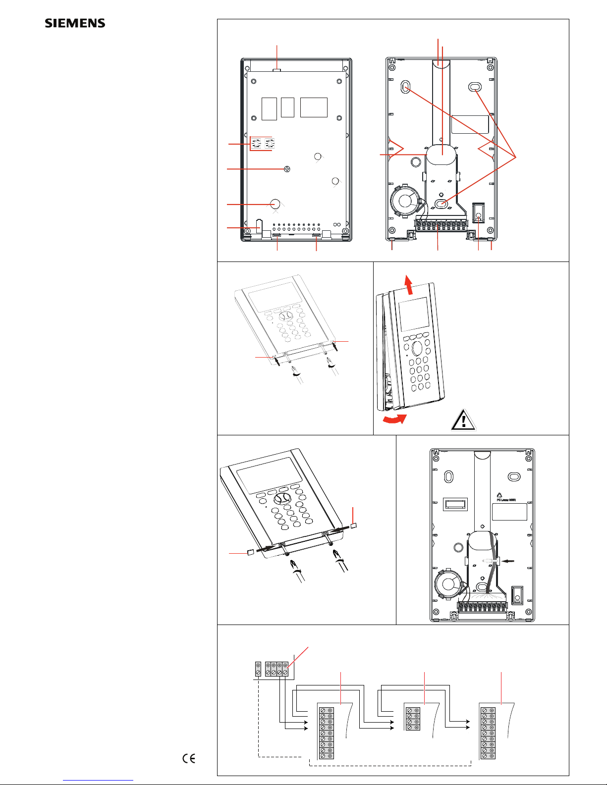
Product overview (Figure 1)
1 Lugs holding the PCB
2 Tamper switch
3 Card Reader (only SPCK 623)
4 Fixing screw for printed circuit board
5 Rotary switches
6 Breakout
7 Cable entry
8 Holes for fastening
9 Lugs
10 Corrugated-head screw for arcing contact
11 Screw terminal
12 Cable duct
Installation
Opening the housing
¾ Loosen the screws by a couple of turns (Fig. 2).
¾ Push the lugs downwards and slightly lift the
cover using a screwdriver (Fig. 2 item 1).
¾ Lift the cover by approx. 1 cm and push it
upwards (Fig. 3).
Connecting cables
¾ Insert the cable through the cable entry hole in the
base (Fig. 1 item 7).
If necessary, carefully remove the breakout pieces
(Fig. 1 item 6).
¾ Connect the individual wires to the screw
terminals (see the following table and Fig. 6).
¾ Attach the cable with a cable tie (Fig. 6).
See Fig. 1, item 11: Contact pins
Contact
pin
Abbreviation Function
1 LS - Loudspeaker negative
(black cable)
2 LS + Loudspeaker positive
(red cable)
3 1 A X-BUS
4 1 B X-BUS
5 2 A X-BUS
6 2 B X-BUS
7 0 V Power supply negative
8 + 12 Power supply positive
9 SCL Not used
10 SDA Not used
Mounting the base
Make sure to mount the unit only on surfaces
that are sufficiently hard and rigid.
¾ Mark 3 holes for the fixing screws (Fig. 1 item 8)
and one for the safety screw (Fig. 1 item 10).
¾ Drill the holes and screw the base.
Mounting the cover
¾ Hook the top of the cover into the base and push
downward.
¾ Push back the upper part of the housing.
Æ The two lugs on the base engage with the
corresponding recesses in the cover.
¾ Tighten the two screws at the bottom of the unit
and seal them using the supplied seals (Fig. 6).
Wiring the X-BUS interface
The X-BUS interface provides connection of
expanders and keypads to the SPC controller. The
X-BUS can be wired in a number of different
configurations depending on the installation
requirements.
NOTE: Maximum System cable length = number of
Expanders and Keypads in the system x maximum
distance for cable type.
Cable type Distance
CQR standard alarm cable 200 m
UTP category: 5 (solid core) 400 m
Belden 9829 400 m
IYSTY 2 x 2 x 0.6 (min) 400 m
Fig. 7 shows the wiring of the X-BUS to an
expander/controller and the following
expander/controller in Spur Configuration. Terminals
3A/3B and 4A/4B (if available for this module) are
only used for using a branch wiring technique. If
using a Spur configuration, the last device is not
wired back to the controller.
See Fig. 7: Wiring of expanders
1
SPC controller
2
Previous expander
3
SPCK620/623
4
Next expander
Please refer to SPC Configuration Manual of
connected controller for further wiring instructions,
shielding, specifications and limitations.
X-BUS addressing
For addressing, reconfiguration, device location,
monitoring, editing of names, X-BUS type of
communication, failure timer please refer to SPC
Configuration Manual.
Technical data
Operating
current
SPCK620:
Max. 155 mA at 12 V DC
SPCK623:
Max. 230 mA at 12 V DC
Quiescent
current
SPCK620:
Min. 55 mA at 12 V DC
SPCK623:
Min. 110 mA at 12 V DC
Operating
voltage
9.5 – 14 V DC
LED
indicators
5 status LED’s
Special keys
4 soft keys, 1 multi-dimensional
navigation key
Field bus1)
X-BUS on RS-485 (307 kb/s)
Tamper
contact
On-board front / back tamper
switch
Card reader
SPCK623:
Integrated 125 kHz reader
(EM 4095)
Audio
SPCK623:
Voice annunciation support
Operating
temperature
-10 to +50 °C
Relative
humidity
Max. 90 % (non-condensing)
Colour RAL 9003 (signal white)
Mounting Flat surface, wall-mounted
Housing Plastic enclosure (Polycarbonate)
Dimensions
(W x H x D)
112 x 185 x 28 mm
Weight 0.38 kg
1)
Max. 400 m between devices / cable types IYSTY
2 x 2 x Ø 0.6 mm (min.), UTP cat5 (solid core) or Belden 9829.
Deutsch Installationsanleitung
Achtung:
Lesen Sie vor der Installation und
Verwendung dieses Geräts die
Sicherheitshinweise.
Das Gerät darf nur an einer Stromversorgung
angeschlossen werden, welche der Norm EN
60950-1 / Kapitel 2.5 ("limited power source")
entspricht.
Gefahr von Schäden am Gerät!
¾ Verwenden Sie das Gerät nur in trockenen
Innenräumen.
¾ Setzen Sie sie es weder Tropf- noch
Spritzwasser aus.
¾ Achten Sie darauf, dass die Kontakte an der
Platte staubfrei sind und berühren Sie sie
nicht mit bloßen Händen.
Produktbeschreibung
Das SPCK620 verfügt über Softkeys und ein
großes grafisches Display (LCD ) für eine einfache
Bedienung. Der Funktionsumfang kann mit einem
Schlüsselschalter-Erweiterungsmodul SPCE110
oder einem Anzeige-Erweiterungsmodul SPCE120
erweitert werden.
Das SPCK623 verfügt über einen ProxyKartenleser (125 kHz EM 4095) für einen einfachen
Benutzerzugang, Softkeys, ein großes LC-Display
und unterstützt Sprachansage. Der
Funktionsumfang kann mit einem
Schlüsselschalter-Erweiterungsmodul SPCE110
oder einem Anzeige-Erweiterungsmodul SPCE120
erweitert werden.
Produktübersicht (Abbildung 1)
1 Haltelaschen der Platine
2 Sabotageschalter
3 Kartenleser (nur SPCK 623)
4 Befestigungsschraube für Leiterplatte
5 Drehschalter
6 Durchbruch
7 Kabeleinführung
8 Öffnungen zur Befestigung
9 Laschen
10 Rändelschraube für Kurzschlusskontakt
11 Schraubklemme
12 Kabelführung
Installation
Öffnen des Gehäuses
¾ Lockern Sie die Schrauben mit mehreren
Umdrehungen (Abb. 2).
¾ Drücken Sie die Laschen nach unten und heben
Sie das Gehäuse mit einem Schraubendreher
leicht nach oben ab (Abb. 2 Element 1).
¾ Heben Sie das Gehäuse ca. 1 cm ab und
schieben Sie es dann nach oben (Abb. 3).
Anschließen der Kabel
¾ Führen Sie das Kabel durch die dafür
vorgesehene Öffnung im Unterteil ein
(Abb. 1 Element 7).
Bohren Sie die Durchbruchstelle vorsichtig auf
(Abb. 1 Element 6) (wenn erforderlich).
¾ Schließen Sie die einzelnen Drähte an den
Schraubklemmen an (siehe Tabelle unten und
Abb. 6).
¾ Befestigen Sie das Kabel mit einem Kabelbinder
(Abb. 6).
Siehe Abb. 1, Element 11: Anschlüsse
Anschluss Abkürzung Funktion
1 LS - Lautsprecher negativ
(schwarzes Kabel)
2 LS + Lautsprecher positiv
(rotes Kabel)
3 1 A X-BUS
4 1 B X-BUS
5 2 A X-BUS
6 2 B X-BUS
7 0 V Stromversorgung,
Minuspol
8 + 12 Stromversorgung, Pluspol
9 SCL nicht benutzt
10 SDA nicht benutzt
Montieren des Gehäuses
Montieren Sie das Gerät nur auf ausreichend
harten und festen Oberflächen.
¾ Markieren Sie die Lage der drei Bohrungen für die
Befestigungsschrauben (Abb. 1, Element 8) und
die Bohrung für die Sicherungsschraube (Abb. 1,
Element 10).
¾ Bohren Sie die Löcher für die
Befestigungsschrauben und schrauben Sie das
Unterteil fest.
Gehäusemontage
¾ Gehäuseoberteil in das Unterteil einhaken und
nach unten drücken.
¾ Gehäuseoberteil nach hinten schieben.
Æ Die beiden Laschen am Unterteil passen in de
entsprechenden Aussparungen im Oberteil.
¾ Ziehen Sie die beiden Schrauben an der
Unterseite an und dichten Sie sie mit den
mitgelieferten Plomben ab (Abb. 6).
Verdrahtung der X-BUS-Schnittstelle
Die X-BUS-Schnittstelle stellt die Verbindungen von
Erweiterungsmodulen und Bedienteilen zur SPCZentrale bereit. Der X-BUS kann je nach
Anforderungen an die Anlage auf unterschiedliche
Weise verdrahtet werden.
HINWEIS: Maximale Systemkabellänge = Anzahl
von Erweiterungsmodulen und Bedienteilen im
System mal maximale Entfernung je nach Kabeltyp.
Kabeltyp Abstand
CQR Standard-Alarmkabel 200 m
UTP-Kategorie: 5 (Massivdrahtleiter) 400 m
Belden 9829 400 m
IYSTY 2 x 2 x 0.6 (min.) 400 m
Abb. 7 zeigt die Verdrahtung des X-BUS mit einem/r
Erweiterungsmodul/Zentrale und das/die folgende/n
Erweiterungsmodul/Zentrale in
Stichleitungskonfiguration. Die Klemmen 3A/3B und
4A/4B (wenn an diesem Modul vorhanden) werden
nur für Abzweigverdrahtungen verwendet. Bei einer
Stichleitungskonfiguration hat das letzte Gerät keine
Rückleitung zur Zentrale.
Siehe Abb. 7: Verdrahtung von
Erweiterungsmodulen
1
SPC Zentrale
2
Vorangegangene Erweiterung
3
SPCK620/623
4
Nächste Erweiterung
Weitere Einzelheiten zur Verdrahtung und
Abschirmung sowie Spezifikationen und
Einschränkungen enthält das SPC
Konfigurationshandbuch der angeschlossener
Zentrale.
X-BUS-Adressierung
Einzelheiten zu Adressierung, Neukonfiguration,
Geräteanordnung, Überwachung,
Namensbearbeitung, X-BUS-Kommunikationstyp,
Ausfall-Timer enthält das SPC
Konfigurationshandbuch.
Technische Daten
Betriebsstrom
SPCK620:
Max. 155 mA bei 12 V DC
SPCK623:
Max. 230 mA bei 12 V DC
Ruhestrom
SPCK620:
Min. 55 mA bei 12 V DC
SPCK623:
Min. 110 mA bei 12 V DC
Betriebsspannung 9,5 - 14 V DC
LED-Anzeigen 5 Zustands-LEDs
Sondertasten
4 Softkeys, 1 Mehrdimensions-
Navegations-Taste
Feldbus1)
X-BUS über RS485
(307 kBit/s)
Sabotagekontakt
Onboard-Schalter für
Sabotageschutz Frontplatte /
Rückseite
Kartenleser
SPCK623:
Integrierter 125 kHz-Leser (EM
4095)
Audio
SPCK623:
Unterstützt Sprachansage
Betriebstemperatur
-10 bis +50 ℃
Rel. Luftfeuchtigkei
t
Max. 90%
(nicht kondensierend)
Farbe RAL 9003 (Signalweiß)
Montage
Ebener Untergrund,
Wandmontage auf Putz
Gehäuse
Kunststoffgehäuse
(Polykarbonat)
Abmessungen
(B x H x T)
112 x 185 x 28 mm
Gewicht 0,38 kg
1)
Max. 400 m zwischen Geräten / Kabel vom Typ
IYSTY 2 x 2 x Ø 0.6 mm (min.), UTP cat5 (Massivdrahtleiter)
oder Belden 9829.
 Loading...