

Siemens SPC4000 Installation & Configuration Manual
Intrusion Control Panel
SPC4000
Installation&Configuration
Manual
Building Technologies
Fire Safety & Security Products

Data and design subject to change without notice. / Supply subject to availability.
© 2008 Copyright by
Siemens Building Technologies
We reserve all rights in this document and in the subject thereof. By acceptance of the document the recipient acknowledges these rights
and undertakes not to publish the document nor the subject thereof in full or in part, nor to make them available to any third party without our
prior express written authorization, nor to use it for any purpose other than for which it was delivered to him.

Contents
1 Security ....................................................................................................9
1.1 Target group..............................................................................................9
1.2 General safety instructions .......................................................................9
1.2.1 General information...................................................................................9
1.2.2 Transport.................................................................................................10
1.2.3 Setup.......................................................................................................10
1.2.4 Operation ................................................................................................10
1.2.5 Service and maintenance .......................................................................11
1.3 Meaning of the written warning notices ..................................................11
1.4 Meanings of the hazard symbols ............................................................12
2 Directives and Standards.....................................................................13
2.1 EU Directives ..........................................................................................13
3 Technical Data.......................................................................................14
3.1 SPC4000.................................................................................................14
3.2 Keypad ....................................................................................................14
3.3 8 Input / 2 Output Expander....................................................................16
3.4 8 Output Expander..................................................................................17
3.5 Wireless Expander..................................................................................17
4 Product description ..............................................................................18
4.1 SPC Features..........................................................................................19
5 Mounting System Equipment ..............................................................20
5.1 Mounting Controller Enclosures..............................................................20
5.1.1 Standard Enclosure ................................................................................20
5.2 Mounting a keypad..................................................................................21
5.3 Mounting an expander ............................................................................21
6 Controller Hardware .............................................................................22
7 Wiring the System.................................................................................24
7.1 Wiring the X-BUS Interface.....................................................................24
7.1.1 Spur (Chain) Configuration .....................................................................25
7.1.2 Star (Multi-drop) Configuration................................................................26
7.2 Wiring of Branch Expander .....................................................................28
7.3 Wiring the Relay Output..........................................................................29
7.4 Wiring the Zone Inputs............................................................................30
7.5 Wiring an External SAB Bell ...................................................................32
7.6 Wiring an Internal Sounder ..................................................................... 32
7.7 Installing Plug-in Modules .......................................................................33
7.8 Wireless Receiver Module ...................................................................... 33
7.8.1 Installing a Wireless Receiver Module....................................................33
7.8.2 Installing an External Antenna ................................................................34
7.8.3 Installing an External Antenna with Mounting Bracket............................34
8 Keypad User Interface ..........................................................................35
8.1 Keypad Display .......................................................................................37
8.2 Data entry on the SPC Keypad...............................................................38
8.2.1 Entering Numeric values.........................................................................38
8.2.2 Entering Text........................................................................................... 38
8.2.3 Selecting a Programming Option............................................................38
Siemens Building Technologies
Fire Safety & Security Products 09.2008
3

9
Starting the System ..............................................................................39
9.1 Engineer Modes ......................................................................................39
9.2 Programming Tools.................................................................................39
9.2.1 Fast Programmer ....................................................................................40
9.3 Configuring Start-up Settings..................................................................40
9.4 Creating System Users ...........................................................................41
9.5 Configuring and Using the Portable ACE Profile ....................................42
9.6 Configuring 868MHz Wireless Fob Devices ...........................................42
9.6.1 Clearing Alerts Using the Wireless FOB Device .....................................42
10 Engineer Programming Via the Keypad .............................................43
10.1 System Status .........................................................................................43
10.2 Configuring Communication Modules .....................................................43
10.2.1 Configuring a GSM or PSTN Modem......................................................44
10.3 Variables .................................................................................................46
10.3.1 Security Grade ........................................................................................48
10.3.2 Application...............................................................................................49
10.3.3 System Areas..........................................................................................49
10.3.4 Partset A / Partset B................................................................................49
10.3.5 Call ARC Mssg........................................................................................50
10.3.6 Keyfob Restore .......................................................................................50
10.3.7 User Duress ............................................................................................50
10.3.8 Retrigger..................................................................................................50
10.3.9 Bell on 1st................................................................................................51
10.3.10 Bell on Failed to Set (FTS)......................................................................51
10.3.11 Strobe on Failed to Set (FTS) .................................................................51
10.3.12 Code Digits..............................................................................................51
10.3.13 Open Zones.............................................................................................51
10.3.14 Show State..............................................................................................52
10.3.15 EOL Resistance ......................................................................................52
10.3.16 SMS Auth Mode ......................................................................................52
10.3.17 Pace and Pin...........................................................................................52
10.3.18 Restore on Unset ....................................................................................52
10.3.19 Offline Tamper ........................................................................................53
10.4 Timers .....................................................................................................54
10.4.1 Ext Bell Time ...........................................................................................56
10.4.2 Int Bell Time ............................................................................................56
10.4.3 Ext Bell Delay..........................................................................................56
10.4.4 Strobe Time.............................................................................................57
10.4.5 Chime Time.............................................................................................57
10.4.6 Dialler Delay............................................................................................57
10.4.7 Soak Days...............................................................................................57
10.4.8 Dknock Delay ..........................................................................................57
10.4.9 Mains Sig Delay ......................................................................................58
10.4.10 Keypad Timeout ......................................................................................58
10.4.11 Wireless Fail to Set (FTS)*......................................................................58
10.4.12 Wireless Lost* .........................................................................................58
10.4.13 Engineer Access .....................................................................................58
10.4.14 Entry Time...............................................................................................59
10.4.15 Exit Time .................................................................................................59
10.4.16 Fullset Bell...............................................................................................59
10.4.17 Fullset Strobe ..........................................................................................59
10.4.18 Final Exit..................................................................................................59
10.4.19 Tech Delay ..............................................................................................60
10.4.20 Fail to Set ................................................................................................60
4
Siemens Building Technologies
Fire Safety & Security Products 09.2008

10.5 Areas.......................................................................................................61
10.5.1 Add..........................................................................................................62
10.5.2 Delete......................................................................................................62
10.5.3 Edit ..........................................................................................................63
10.6 X-BUS .....................................................................................................64
10.6.1 X-BUS Programming ..............................................................................66
10.6.2 Reconfigure.............................................................................................66
10.6.3 Locate .....................................................................................................66
10.6.4 Monitor ....................................................................................................67
10.6.5 Edit ..........................................................................................................67
10.7 Wireless ..................................................................................................68
10.7.1 Add..........................................................................................................68
10.7.2 Remove...................................................................................................68
10.7.3 Ext Antenna.............................................................................................68
10.7.4 Supervision .............................................................................................68
10.7.5 Sensor Type............................................................................................68
10.8 Zone Types and Assignable Attributes ...................................................68
10.9 Programming Zones ...............................................................................69
10.10 Outputs....................................................................................................71
10.10.1 Outputs Types and Output Ports ............................................................71
10.10.2 Programming Outputs.............................................................................73
10.11 Communication .......................................................................................75
10.11.1 Modems ..................................................................................................75
10.11.2 Central Station ........................................................................................76
10.12 Test .........................................................................................................77
10.12.1 Bell Test ..................................................................................................78
10.12.2 Walk Test ................................................................................................ 78
10.12.3 Zone Monitor ...........................................................................................78
10.12.4 Output Test .............................................................................................79
10.12.5 Soak Test ................................................................................................80
10.12.6 Audible Options....................................................................................... 80
10.13 Utilities.....................................................................................................81
10.13.1 Sys Software ...........................................................................................81
10.13.2 Defaults ...................................................................................................82
10.13.3 Fast Programmer ....................................................................................82
10.13.4 SPC Pro ..................................................................................................82
10.14 Isolate......................................................................................................82
10.15 Event Log ................................................................................................ 83
10.16 Change Code ..........................................................................................83
10.17 Users.......................................................................................................83
10.17.1 Adding .....................................................................................................83
10.17.2 Editing .....................................................................................................84
10.17.3 Deleting ...................................................................................................84
10.18 Setup SMS .............................................................................................. 84
10.19 Installer Text............................................................................................85
11 User Access Via the Keypad................................................................86
11.1 Setting the System: FULLSET ................................................................ 86
11.2 Setting the system: PARTSET A ............................................................86
11.3 Setting the System: PARTSET B............................................................87
11.4 Failing to Set the System ........................................................................87
11.5 Force Setting the System........................................................................87
11.6 Unsetting the System..............................................................................88
11.7 Restoring an Alarm Activation (Alert)......................................................88
11.8 Coded Restore ........................................................................................89
Siemens Building Technologies
Fire Safety & Security Products 09.2008
5

12
User Menus Via the Keypad.................................................................90
12.1 Inhibiting a Zone......................................................................................90
12.2 Viewing Inhibited Zones ..........................................................................90
12.3 Inhibiting a Zone or Fault ........................................................................91
12.4 Isolating a Zone or Fault .........................................................................91
12.5 Setting the Time and Date ......................................................................92
12.6 Performing Tests on the System.............................................................92
12.7 Performing a Walk Test...........................................................................93
12.8 Viewing the Event Log ............................................................................93
12.9 Enabling the Chime Function..................................................................94
12.10 Adding, Editing, and Deleting Users .......................................................94
12.10.1 Adding .....................................................................................................94
12.10.2 Editing .....................................................................................................95
12.10.3 Deleting ...................................................................................................95
12.11 Changing a User Code............................................................................96
12.12 Using SMS ..............................................................................................96
12.12.1 SMS Events.............................................................................................97
12.12.2 SMS Control............................................................................................98
12.12.3 SMS Commands .....................................................................................99
12.13 Allowing Engineer Access.......................................................................99
12.14 Language ................................................................................................99
12.15 Status Summary......................................................................................99
12.15.1 Zones ....................................................................................................100
12.15.2 System Alerts ........................................................................................100
12.15.3 Expanders .............................................................................................100
12.15.4 Keypads ................................................................................................100
12.16 Log ........................................................................................................101
12.17 Utilities...................................................................................................101
12.17.1 Allowing Engineer/Manufacturer Access ..............................................101
12.17.2 Changing Access Code.........................................................................101
12.17.3 Setting the Time and Date ....................................................................101
12.18 SMS.......................................................................................................101
12.18.1 SMS Events...........................................................................................102
12.18.2 SMS Control..........................................................................................102
12.19 X-10 Outputs .........................................................................................102
13 Using the Fast Programmer...............................................................103
13.1 Connecting the Fast Programmer to a PC............................................103
13.2 Connecting the Fast Programmer to the SPC Controller......................104
13.3 Configuring with the Fast Programmer .................................................105
13.4 Firmware Upgrade using the keypad ....................................................105
14 Intruder Alarm Functionality ..............................................................106
14.1 Commercial Mode Operation ................................................................106
14.2 Domestic Mode Operation ....................................................................106
14.3 Full and Local Alarms on the SPC ........................................................107
15 System Examples and Scenarios......................................................108
15.1 When to Use a Common Area ..............................................................108
6
Siemens Building Technologies
Fire Safety & Security Products 09.2008

16 Appendix..............................................................................................110
16.1 Appendix A: Keypad User Menu...........................................................110
16.2 Appendix B: Keypad Engineer Menu....................................................111
16.3 Appendix C: Keypad Full Engineer Menu.............................................112
16.4 Appendix E: SPC Controller Status LEDs ............................................113
16.5 Appendix F: Powering Expanders from the Auxiliary Power Terminals114
16.6 Appendix G: Calculating the Battery Power Requirements ..................116
16.7 Appendix H: Domestic and Commercial Mode Default Settings ..........117
16.8 Appendix I: Wiring of X10 Interface to the SPC Controller ...................118
16.9 Appendix J: SIA Codes .........................................................................118
16.10 Appendix k: System Variables ..............................................................121
16.11 Appendix L: Zone Types .......................................................................122
16.12 Appendix M: Zone Attributes.................................................................123
16.13 Appendix N: Zone Types and Assignable Attributes ............................124
16.14 Appendix O: Wiring of Mains Cable to the SPC Controller...................126
17 Keyword index.....................................................................................127
Siemens Building Technologies
Fire Safety & Security Products 09.2008
7

8
Siemens Building Technologies
Fire Safety & Security Products 09.2008

1 Security
1.1 Target group
Security
Target readers Qualification Activity Condition of the
Installation personnel Technical training for
Operational startup
personnel
building or electrical
installations.
Has appropriate
technical training with
regard to the tasks and
the products, devices or
systems to be put in
service.
1.2 General safety instructions
1.2.1 General information
– Read the general safety precautions before operating the unit.
– Keep this document for later reference.
– Always pass this document on together with the product.
– Please also take into account any additional country-specific, local safety
standards or regulations concerning project planning, operation and disposal of
the product.
Assembles and installs
the hardware
components on site.
Puts the device or
system which is readily
assembled and installed
on site into service.
equipment
Individual components
that need to be
assembled and
installed.
New, readily assembled
and installed device or
modified device.
Liability claim
– Do not connect the device to the 230 V supply network if it is damaged or any
parts are missing.
– Do not make any changes or modifications to the device unless they are
expressly mentioned in this manual and have been approved by the
manufacturer.
– Use only spare parts and accessories that have been approved by the
manufacturer.
Siemens Building Technologies
Fire Safety & Security Products 09.2008
9

Security
1.2.2 Transport
1.2.3 Setup
Unit damage during transport
– Keep the packaging material for future transportation.
– Do not expose the device to mechanical vibrations or shocks.
Radio interference with other devices in the environment
– When handling modules that are susceptible to electrostatic discharge, please
observe the ESD guidelines.
Damage due to unsuitable mounting location
– The environmental conditions recommended by the manufacturer must be
observed. See Section
– Do not operate the device close to sources of powerful electromagnetic
3 Technical Data.
radiation.
1.2.4 Operation
Danger of electrical shock due to incorrect connection
– Connect the device only to power sources with the specified voltage. Voltage
supply requirements can be found on the rating label of the device.
– Make sure the device is permanently connected to the electricity supply; a
readily accessible disconnect device must be provided.
– Make sure the circuit the device is connected to is protected with a 16 A (max.)
fuse. Do not connect any devices from other systems to this fuse.
– This device is designed to work with TN power systems. Do not connect the
device to any other power systems.
– Electrical grounding must meet the customary local safety standards and
regulations.
– Primary supply cables and secondary cables should be routed such that they do
not run in parallel or cross over or touch one anther inside the housing.
– Telephone cables should be fed into the unit separately from other cables.
Risk of cable damage due to stress
– Make sure that all outgoing cables and wires are sufficiently strain-relieved.
Dangerous situation due to false alarm
– Make sure to notify all relevant parties and authorities providing assistance
before testing the system.
– To avoid panic, always inform all those present before testing any alarm
devices.
10
Siemens Building Technologies
Fire Safety & Security Products 09.2008

Danger of explosion or burn hazard if the battery is improperly installed
– When inserting new batteries make sure the battery poles are correctly
positioned.
– Use only batteries that have been approved by the manufacturer (type: sealed
cell valve-regulated).
– Do not shorten the battery pins.
– Do not expose the battery to fire or high temperatures.
– Do not disassemble the battery.
– Discard used batteries according to local regulations.
– Make sure to insert the battery correctly and to fasten the battery strap or clip
provided for this purpose.
1.2.5 Service and maintenance
Danger of electrical shock during maintenance
– Maintenance work must only be carried out by trained specialists.
Security
– Always disconnect the power cable and other cables from the main power
supply before performing maintenance.
Danger of electrical shock while cleaning the device
– Do not use liquid cleaners or sprays that contain alcohol, spirit or ammonia.
1.3 Meaning of the written warning notices
Signal Word Type of Risk
DANGER Danger of death or severe bodily harm.
WARNING Possible danger of death or severe bodily harm.
CAUTION Danger of minor bodily injury or property damage
IMPORTANT Danger of malfunctions
11
Siemens Building Technologies
Fire Safety & Security Products 09.2008

Security
1.4 Meanings of the hazard symbols
WARNING Warning of a hazard area
WARNING Warning of dangerous electrical voltage
12
Siemens Building Technologies
Fire Safety & Security Products 09.2008

2 Directives and Standards
2.1 EU Directives
This product complies with the requirements of the European Directives
2004/108/EC “Directive of Electromagnetic Compatibility” and 2006/95/EC “Low
Voltage Directive”. The EU declaration of conformity is available to the responsible
agencies at:
Siemens Building Technologies
Fire & Security Products GmbH & Co. oHG
76181 Karlsruhe
European Directive 2004/108/EC „Electromagnetic Compatibility”
Compliance with the European Directive 2004/108/EC has been proven by testing
according to the following standards:
emc emission EN 55022 Class B
emc immunity EN 50130-4
Directives and Standards
European Directive 2006/95/EC „Low-Voltage Directive”
Compliance with the European Directive 2006/95/EC has been proven by testing
according to the following standard:
Safety: EN 60950-1
13
Siemens Building Technologies
Fire Safety & Security Products 09.2008

Technical Data
3 Technical Data
3.1 SPC4000
Mains voltage 230 VAC, +10 to -15 %, 50 Hz
Fuse 250 mA T
Power consumption 100 mA @ 230 V AC
Auxiliary power (nominal) 1) Max. 750 mA @ 12 VDC
Battery Optional
Battery type Sealed cell valve-regulated
Battery capacity Max. 7 AH / 12 V
Battery charger Max. 24h for 80 % of battery capacity
Operating voltage n.a.
Current consumption 1) Max. 100 mA @ 12 V DC
Number of on-board zones 8
EOL resistor Dual 4K7 (default), other resistor combinations configurable
1 internal bell (max. 400 mA resistive),
Number of on-board open collector
outputs.
Number of on-board relays 1 strobe, 30 V / 1 A (resistive switching current)
Field bus 2) X-BUS on RS-485 (307 kb/s)
Interfaces
Tamper contact
Operating temperature 5 - 40 °C
Relative humidity Max. 90 % (no condensation)
Housing protection IP30
Colour RAL 9003
Housing protection class Class II Indoor General
Mounting Surface, wall mounted
Housing material Steel, > 1.2 mm
Housing Metal enclosure
Housing can contain up to 1 additional Expander (size 150 mm x 82 mm)
Standards
1)
For EN compliance the supplied current needs to be supported by the battery for required stand by time
2)
Max. 400m between devices with cable types IYSTY 2 x 2 x Ø 0,6 mm (min.), UTP cat5 (solid core) or Belden 9829
1 external bell (max. 400 mA resistive),
3 general outputs (each max. 400 mA resistive,
supplied via auxiliary output)
1 x X-BUS (1 spur),
1 x RS232 (RJ45 ports, for X-10 or external communications),
1 x USB (PC connection for terminal program access),
1 x SPC Fast Programmer
On-board front cabinet spring tamper
+ 2 auxiliary tamper inputs
Designed to meet
EN50131-1:2006 (Grade 2)
TS50131-3:2003 (Grade 2)
EN50131-6:2008 (Grade 2)
14
Siemens Building Technologies
Fire Safety & Security Products 09.2008

3.2 Keypad
LC-display 2 x 16 characters
Special function keys Multi dimensional navigation key and 2 soft keys
Status LEDs 3
Card reader SPCK421: 125 kHz, EM 4102 or compatible (e.g. SiPASS)
Card read distance SPCK421: 10 mm
Operating voltage 9.5 – 14 V DC
Current consumption 2)
Field bus 3) X-BUS on RS-485 (307 kb/s)
Tamper contact Front/rear spring tamper
Operating temperature 5 - 40 °C
Relative humidity Max. 90 % (no condensation)
SPCK420: Min: 60 mA at 12 V DC, Max. 70 mA at 12 V DC
SPCK421: Min. 90 mA at 12 V DC, Max. 110 mA at 12 V DC
Technical Data
Housing protection IP30
Housing protection class Class II Indoor General
Housing material ABS
Colour RAL 9003
Mounting Surface, wall-mounted, height of 1.30 - 1-50 m
Designed to meet
Standards
1)
For EN compliance the supplied current needs to be supported by the battery for required stand by time
2)
Max. 400m between devices with cable types IYSTY 2 x 2 x Ø 0,6 mm (min.), UTP cat5 (solid core) or Belden 9829
EN50131-1:2006 (Grade 3),
TS50131-3:2003 (Grade 3)
15
Siemens Building Technologies
Fire Safety & Security Products 09.2008

Technical Data
3.3 8 Input / 2 Output Expander
Operating voltage 9.5 – 14 V DC
Current consumption 1) Min. 45 mA at 12 V DC
Max. 80 mA at 12 V DC
Number of on-board zones 8
EOL resistor Dual 4K7 (default), other resistor combinations config.
Number of on-board relays 2 single-pole changeover, 30 V DC / 1 A
(resistive switching current)
Field bus 2) X-BUS on RS485 (307 kb/s)
Interfaces X-BUS (In, Out, Branch)
Tamper contact On-board front cabinet spring tamper
Operating temperature 5 - 40 °C
Relative humidity Max. 90 % (no condensation)
Housing protection IP30
Colour RAL 9003
Housing protection class Class II Indoor General
Mounting Surface, wall-mounted
Housing material ABS
Housing Plastic enclosure
Standards Designed to meet
EN50131-1:2006 (Grade 3),
1)
For EN compliance the supplied current needs to be supported by the battery for required stand by time
2)
Max. 400m between devices with cable types IYSTY 2 x 2 x Ø 0,6 mm (min.), UTP cat5 (solid core) or Belden 9829
TS50131-3:2003 (Grade 3)
16
Siemens Building Technologies
Fire Safety & Security Products 09.2008

3.4 8 Output Expander
Operating voltage 9.5 – 14 V DC
Current consumption 1)
Number of on-board relays
Field bus 2) X-BUS on RS485 (307 kb/s)
Interfaces X-BUS (In, Out, Branch)
Tamper contact On-board front cabinet spring tamper
Operating temperature 5 - 40 °C
Relative humidity Max. 90 % (no condensation)
Housing protection IP30
Colour RAL 9003
Housing protection class Class II Indoor General
Mounting Surface, wall-mounted
Min. 55 mA at 12 V DC
Max. 180 mA at 12 V DC
8 single-pole changeover, 30 V DC / 1 A
(resistive switching current)
Technical Data
Housing material ABS
Housing Plastic enclosure
Designed to meet
Standards
1)
For EN compliance the supplied current needs to be supported by the battery for required stand by time
2)
Max. 400m between devices with cable types IYSTY 2 x 2 x Ø 0,6 mm (min.), UTP cat5 (solid core) or Belden 9829
EN50131-1:2006 (Grade 3),
TS50131-3:2003 (Grade 3)
3.5 Wireless Expander
Wireless features and devices will be available with a later market package.
17
Siemens Building Technologies
Fire Safety & Security Products 09.2008
Product description
4 Product description
The SPC Series Controller is a true hybrid Controller with eight on-board wired
zones that communicate with intruder devices.
The flexible design of the Controller allows the functional components
(PSTN/GSM/RF) to be mixed and matched, improving the capability of the system.
Using this approach, an installer can ensure that an efficient installation with
minimal wiring is achieved.
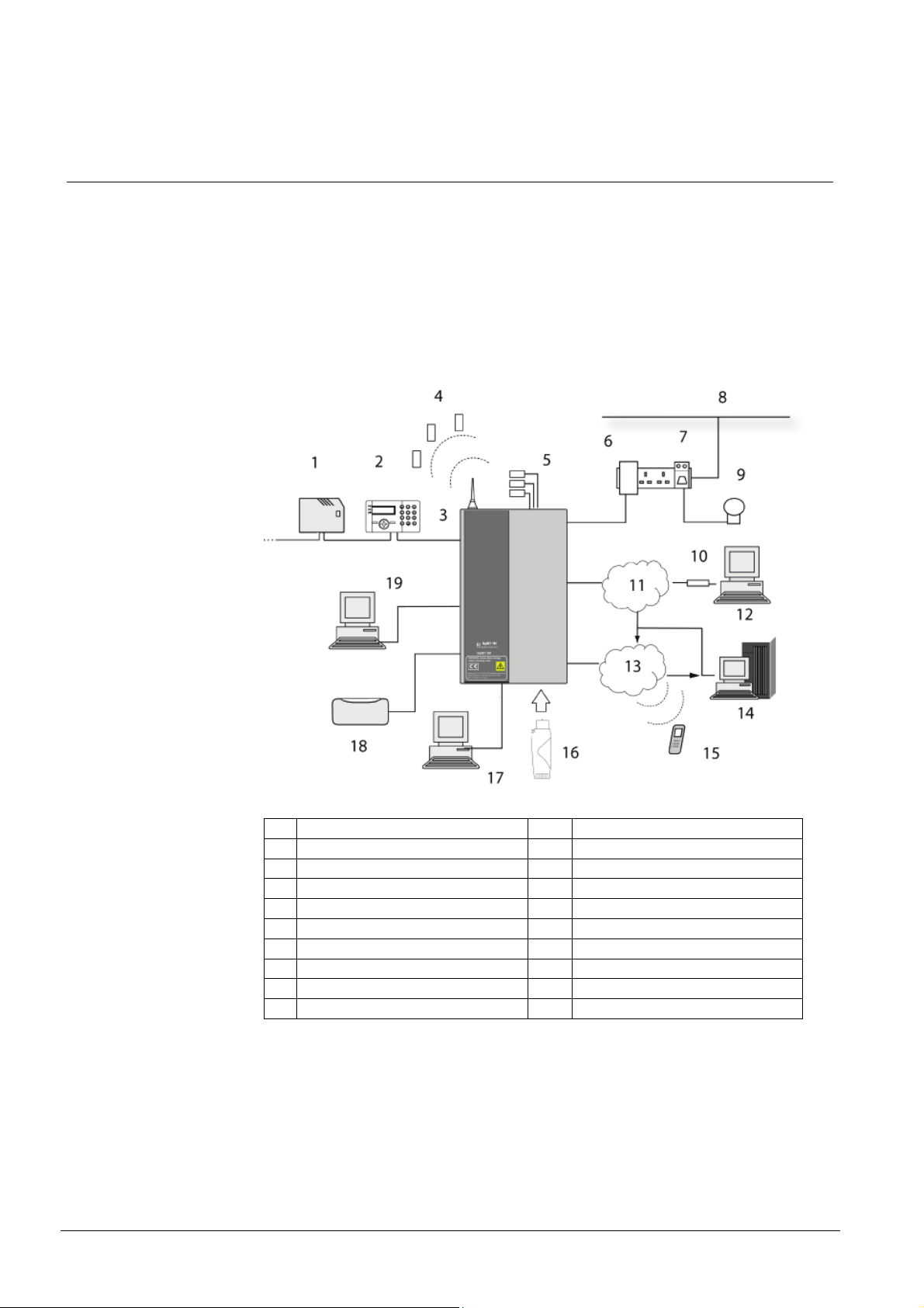
1 Expander 11 PSTN
2 Keypad 12 Remote PC
3 X-Bus 13 GMS
4 Wireless sensors 14 Central station receiver
5 Wired sensors 15 Text messages to mobile phone
6 X10 controller 16 Fast programmer
7 X10 output controller module 17 SPC Pro
8 Power line 18 Bell/strobe
9 Appliance 19 SPC Pro via USB
10 Modem
*Wireless features and devices will be available with a later market package.
Fig. 1 SPC Overview
18
Siemens Building Technologies
Fire Safety & Security Products 09.2008

4.1 SPC Features
The following features are incorporated into the SPC4000 Controller design:
z 8 Inputs with configurable wiring - No End Of Line (NEOL), Single End Of Line
(SEOL), Dual End Of Line (DEOL) and Anti-masking PIR supervision (MPIR)
z 6 Outputs – 3 x open collector, 1 x single pole Relay, 1x External Bell and 1 x
Internal Bell
z Wireless transceiver module (868 Mhz) supporting multiple wireless zones
(Optional)*
z PSTN Modem module (Optional)
z GSM module – Future Release (Optional)
z 1 x X10 Port
z 1 x RS232 Serial port terminal connector Interfaces
z 1 x USB Interface port
z X-BUS Communications Interface – 1 comms channel (1A, 1B)
z Front Tamper spring with tamper by-pass jumper
z PSU interface – AC power in via transformer
z Fast Programmer support – for fast local download of firmware
z SPC Pro programming application
*These features and devices will be available with a later market package.
Product description
19
Siemens Building Technologies
Fire Safety & Security Products 09.2008
Mounting System Equipment
5 Mounting System Equipment
5.1 Mounting Controller Enclosures
The Controller is supplied in two enclosure variations (standard and hinged). Each
enclosure offers easy access and installation within a robust design.
5.1.1 Standard Enclosure
The SPC standard enclosure is supplied with metallic cover. The cover is attached
to the base of the enclosure by two securing screws located on the top and bottom
of the front cover.
To open the enclosure, remove both screws with the appropriate screwdriver and
lift the cover directly from the base.
The standard enclosure contains the SPC Controller Printed Circuit Board (PCB)
mounted on four support pillars. An optional Input/Output module can be mounted
directly beneath the Controller PCB. A battery with capacity of 7AH (max) can be
accommodated below the SPC Controller.
An optional external antenna must be fitted to enclosures with metallic lid if the
wireless functionality* is required. If an antenna is fitted to the unit, it must be
enabled in the firmware.
The SPC standard enclosure provides three screw holes for wall mounting the unit.
To wall mount the enclosure, remove the cover and locate the initial fixing screw
hole at the top of the cabinet. Mark the position of this screw hole on the desired
location on the wall and drill the initial screw hole. Screw the unit to the wall and
mark the position of the bottom two screw hole positions with the unit vertically
aligned.
* Wireless features and devices will be available with a later market package.
20
Siemens Building Technologies
Fire Safety & Security Products 09.2008

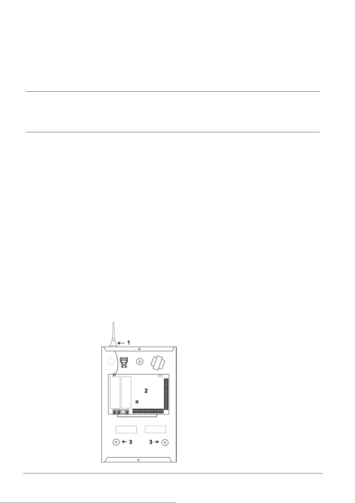
1 Wireless Antenna
NOTE: Wireless features and devices will
be available with a later market package.
2 SPC Controller
3 Wall Mounting Screw Holes
Fig. 2 Standard Enclosure
5.2 Mounting a keypad
For mounting please refer to the corresponding Installation Instruction.
5.3 Mounting an expander
For mounting please refer to the corresponding Installation Instruction.
Mounting System Equipment
21
Siemens Building Technologies
Fire Safety & Security Products 09.2008
Controller Hardware
6 Controller Hardware
The SPC Controller provides eight on-board wired zones and 24 on-board wireless
zones that communicate with intruder devices using the new European standard
wireless frequency 868 MHz*, providing greater security from interference and
jamming. For larger applications the SPC system components can be mixed and
matched to expand both the wired and wireless zones, providing flexibility in cost
effective design and efficient installation with minimal wiring.
*NOTE: Wireless features and devices will be available with a later market package.
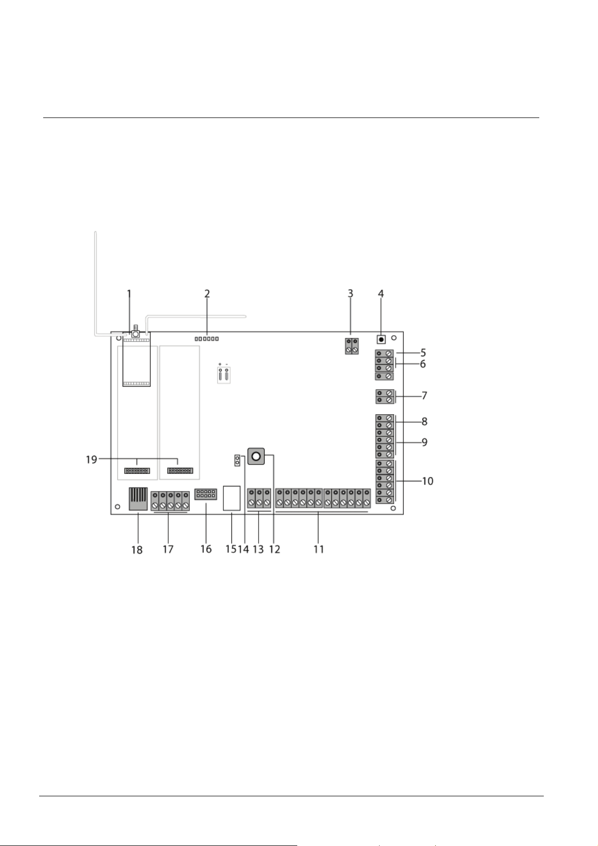
Fig. 3 SPC4000 Controller
22
Siemens Building Technologies
Fire Safety & Security Products 09.2008

Controller Hardware
1 Optional Wireless Module
2 SPC Status LEDs These 6 LEDs display the status of various system parameters as described in Section
3 AC Power Input The mains AC input voltage is applied to this 2-pin connection via a transformer contained
4 Reset Switch Press this switch once to reset the SPC Controller. To reset the programming settings to
5 Earth Connection Terminal This terminal provides an earth connection point providing a common ground for the
6 Auxiliary 12 V Output The SPC Controller provides an auxiliary 12 V DC output that can be used to supply power
7 X-BUS Interface This is the SPC communications bus used to network Expanders together on the system.
8 On-board Outputs Outputs OP4, OP5, and OP6 are 12 V open collector resistive outputs that share a 400 mA
9 Relay Output The SPC Controller provides a 1 A, single-pole, changeover relay that can be used to drive
10 Internal Bell / External Bell Internal and external bell outputs (INT+, INT-, EXT+, EXT-) are resistive outputs with a 400
11 Zone Inputs The Controller provides eight on-board zone inputs that can be monitored using a variety of
12 Front Tamper This on-board front tamper (switch & switch) provides the cabinet tamper protection.
13 Tamper Terminals The Controller provides two additional tamper input terminals that can be connected to
14 Tamper Bypass [LK1] The jumper setting determines the operation of the tamper. The tamper operation can be
15 USB Interface The USB interface is used to access terminal programs.
16 Fast Programmer Port for connecting to the Fast Programmer.
17 Serial Port 1 This RS232 serial port may be used to interface to an X10 protocol device.
18 X10/Serial Port 2 This port may be enabled for connecting to the X-10 port or it may be enabled as a
19 Optional Plug-in Modules A primary (left slot) and back-up (right slot) module can be connected to the SPC
NOTE: Wireless features and devices will be available with a later market package.
16.4 Appendix E: SPC Controller Status LEDs.
in the SPC Enclosure. The earth lead from the mains supply is wired to a connection point
on the metal cabinet.
default and reboot the Controller, hold down the button for 10 seconds and release.
Note: Configuration will be lost.
Controller PCB with ancillary devices.
to Expanders and devices such as latches, bells, etc. See Section
Powering Expanders from the Auxiliary Power Terminals. The maximum deliverable
current is 750 mA.
See Section
channel (1A 1B) for manually addressed Expanders only.
current rating with the auxiliary 12 V Output.
the strobe output on the external bell.
mA current rating. The BHO (Bell Hold Off), TR (Tamper Return), and EXT outputs are
used to connect an external bell to the Controller. The INT+ and INT- terminals are used to
connect to internal devices such as an internal sounder. See Section
Sounder.
supervision configurations. These configurations can be programmed from system
programming. The default configuration is Dual End of Line (DEOL) using resistor values of
4K7. See Section
auxiliary tamper devices to provide increased tamper protection. These terminals should
be shorted when not in use.
overridden by fitting LK1. The engineer must ensure that LK1 is removed before leaving
site for the system to comply with standards.
communications channel with the back-up modem module. If a back-up modem is
installed, ensure no devices are connected to this serial port.
Controller. These modules can be GSM or PSTN modules offering increased
communication functionality. The back-up module should not be connected if serial port 2
interface is connected to an external modem or other device.
7.1 Wiring the X-BUS Interface. SPC4000 supports one communication
7.4 Wiring the Zone Inputs.
16.5 Appendix F:
7.6 Wiring an Internal
23
Siemens Building Technologies
Fire Safety & Security Products 09.2008
Wiring the System
7 Wiring the System
7.1 Wiring the X-BUS Interface
The X-BUS interface provides for the connection of Expanders to the SPC
Controller. The X-BUS can be wired in a number of different confirmations
depending on the installation requirements. The X-BUS interface baud rate is
307kb.
Expander / Expander for all cable types.
Tab. 1 shows the maximum distances between Controller / Expander or
Cable Type Distance
CQR standard alarm cable 200 m
UTP Category: 5 (solid core) 400 m
Belden 9829 400 m
IYSTY 2 x 2 x 0.6 (min) 400 m
Tab. 1 Cable Type and Distance
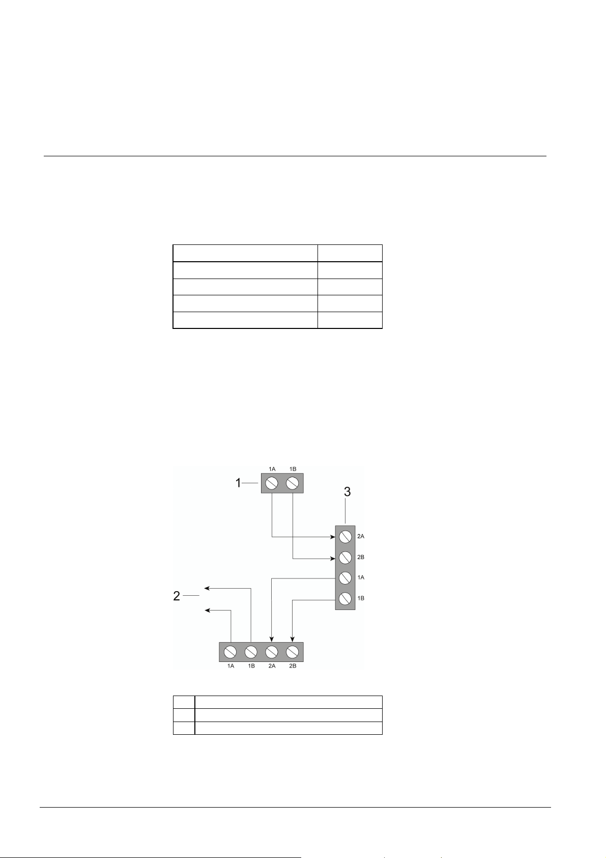
Each device has 2 terminals, 1A and 1B, for connection to Expanders via the XBUS cable. The SPC Controller initiates a detection procedure on power up to
determine the number of Expanders connected on the system and the topology in
which they are connected.
The following modules have Branch Expander wiring capability: 8 Input / 2 Output
Expander, 8 Output Expander. See Section
7.2 Wiring of Branch Expander for
instructions on branch expander wiring.
1 From Previous Expander
2 To Next Expander
3 SPC Controller
Fig. 4 Wiring of Expanders
24
Siemens Building Technologies
Fire Safety & Security Products 09.2008
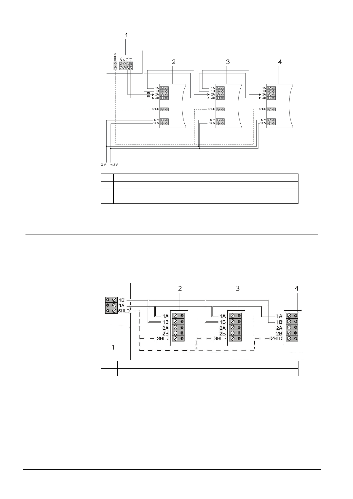
7.1.1 Spur (Chain) Configuration
The Spur, or open loop, cabling method offers a high level of fault tolerance and
may be more convenient on certain installations. In the case of a cable fault or
break, all Expanders and detectors up to the fault continues to be supervised.
On the SPC, only a single port supports a group of Expanders. The last Expander
in an open loop configuration is not wired back to the controller and can be
identified by the fast LED flashing light (one flash every 0.2 seconds approx) when
in Full Engineer programming.
Numbering for the Expanders commences at the Expander nearest to the
Controller and ends with the Expander connected farthest from the SPC Controller.
Eg. if six Expanders are connected in an open loop configuration, then the nearest
Expander on the X-BUS connection is Expander 1, the second nearest Expander is
2, etc. ending with the Expander wired farthest from the SPC Controller, which is
Expander 6.
Within the open loop wiring configuration all Expanders/Keypads are fitted with a
jumper, as default, allowing termination on the device.
Wiring the System
1 Controller
2 Expander Three
3 Expander Two
4 Expander One
Fig. 5 Spur (Chain) Configuration
25
Siemens Building Technologies
Fire Safety & Security Products 09.2008
Wiring the System
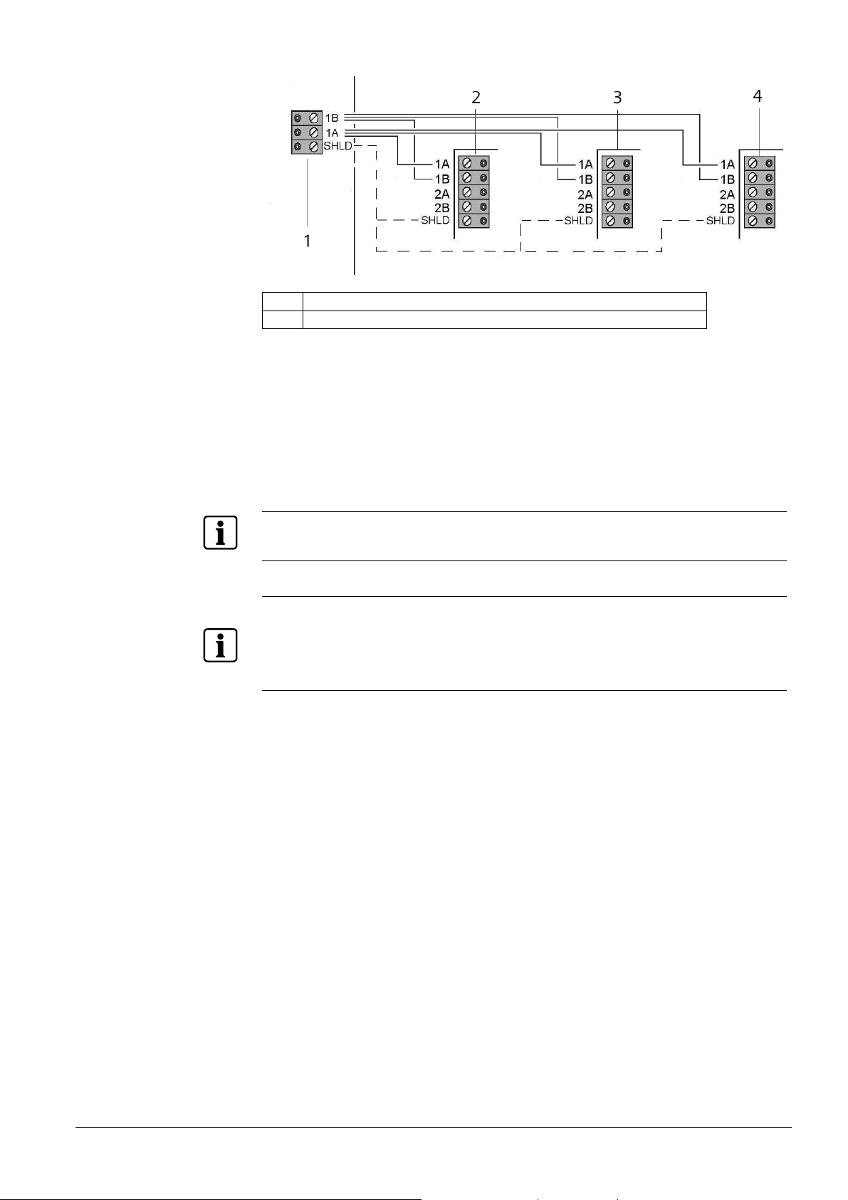
1 SPC Controller X-BUS Terminal Block
2 Expander Three
3 Expander Two
4 Expander One
Fig. 6 Open Loop (Spur) Configuration
7.1.2 Star (Multi-drop) Configuration
The star cabling method is most effective with homes that are prewired with fourcore cable. These configurations allow for a maximum cable length of 200 metres.
A star configuration is established when multiple Expanders are wired back to the
same input channel of the X-BUS on the SPC Controller. See wiring configuration
in
Fig. 7.
1 SPC Controller
2 - 4 Expanders
Fig. 7 Star Configuration
26
Siemens Building Technologies
Fire Safety & Security Products 09.2008
1 SPC Controller
2 - 4 Expanders
Fig. 8 Multi-Drop Configuration
The multi-drop configuration varies in that each Expander uses the same
communication channel as it wires onto the next Expander, with all Expanders
using the same input channel. See multi-drop configuration in
A cable break in the X-BUS connection results in disconnection with the single
Expander on that cable. All other Expanders are unaffected as there are separate
communication paths. A short in the cable renders all Expanders disabled.
NOTE
On a Star wiring or Multi-Drop configuration, all Expanders should not have a jumper fitted (no
termination).
NOTE
Cable Shielding
The shielding terminals (SH) should only be used for cables types with shielding (e.g. Belden 9829). If
shielding is required (i.e. sites with high electric field interference) connect the cable shield to the SH
terminals on the SPC Controller and all networked Expanders. Earth the SH terminal on the Controller
ONLY. Do NOT earth the SH terminal on any of the Expanders.
Wiring the System
Fig. 8.
27
Siemens Building Technologies
Fire Safety & Security Products 09.2008

Wiring the System
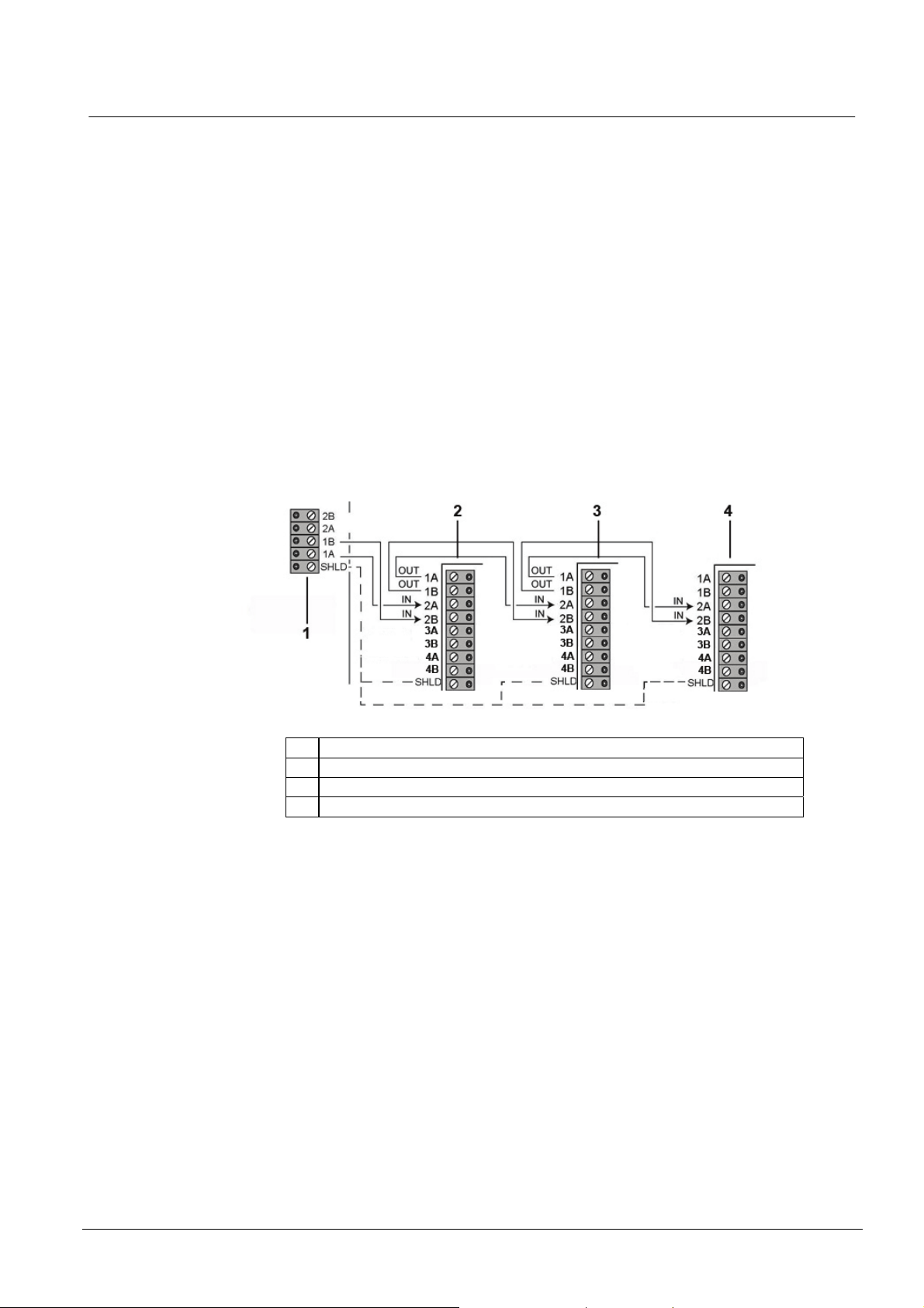
7.2 Wiring of Branch Expander
The wiring of the X-BUS interface with eight terminals 1A/1B to 4A/4B provides for
the connection of an additional branch Expander.
If the branch is not used then the terminals 1A/1B are used to connect to the next
Expander/Keypad. Terminals 3A/3B 4A/4B are then not used. Branches are on all
Expanders except Keypads.
1 Previous Expander
2 Wireless Gateway Expander (NOTE: Wireless
features and devices will be available with a later
market package.)
3 Next Expander
4 Branch
Fig. 9 Wiring of a Branch Expander
28
Siemens Building Technologies
Fire Safety & Security Products 09.2008
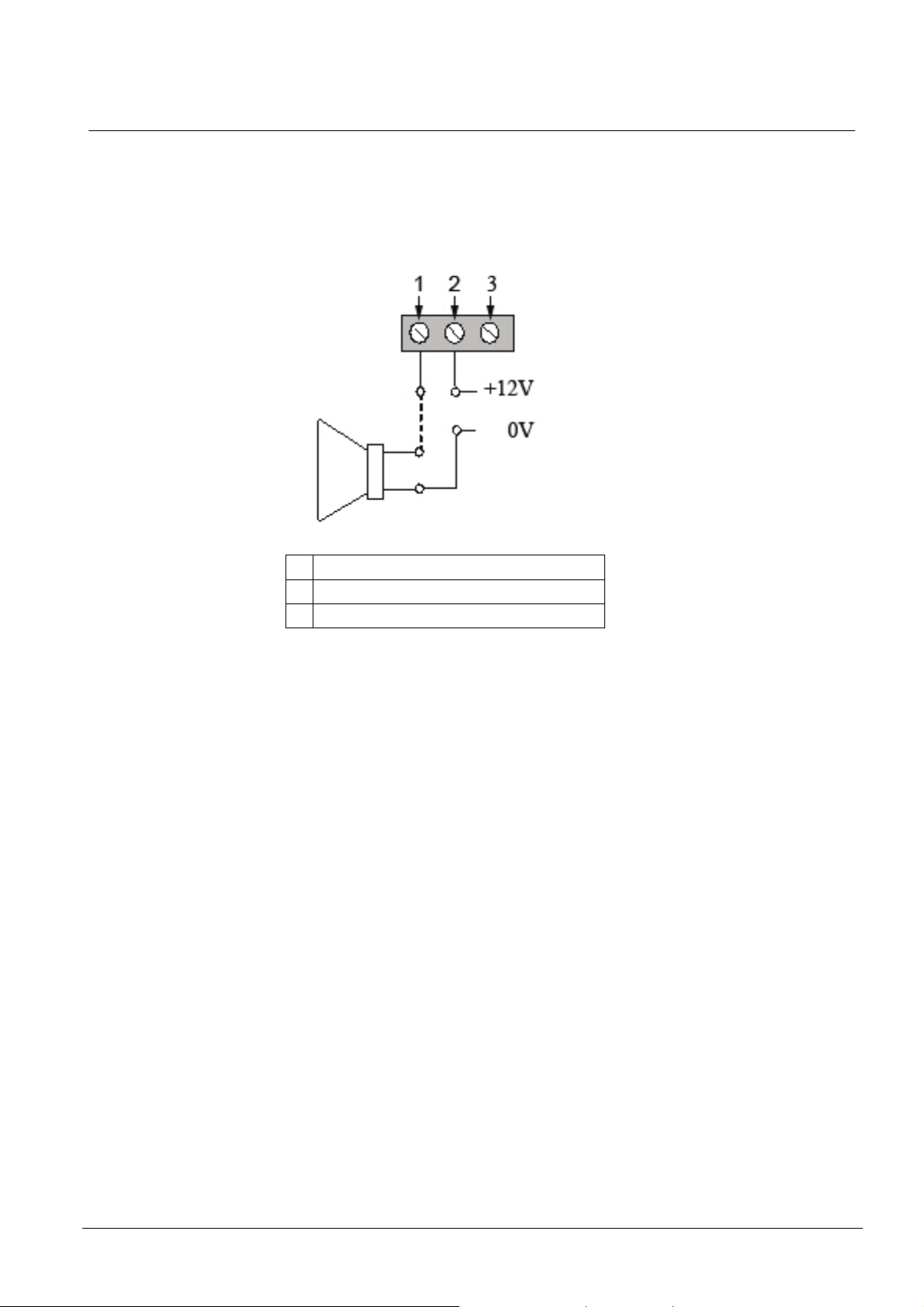
7.3 Wiring the Relay Output
The SPC Controller has one on-board 1-Amp single pole changeover relay that
can be assigned to any of the SPC system outputs. This relay output can switch a
rated voltage of 30 V DC (non-inductive load).
When the relay is activated the Common terminal connection (COM) is switched
from the Normally Closed terminal (NC) to the Normally Open terminal (NO).
Wiring the System
1 Normally Open terminal (NO)
2 Common terminal connection (COM)
3 Normally Closed terminal (NC)
Fig. 10 Standard Wiring
29
Siemens Building Technologies
Fire Safety & Security Products 09.2008
Wiring the System
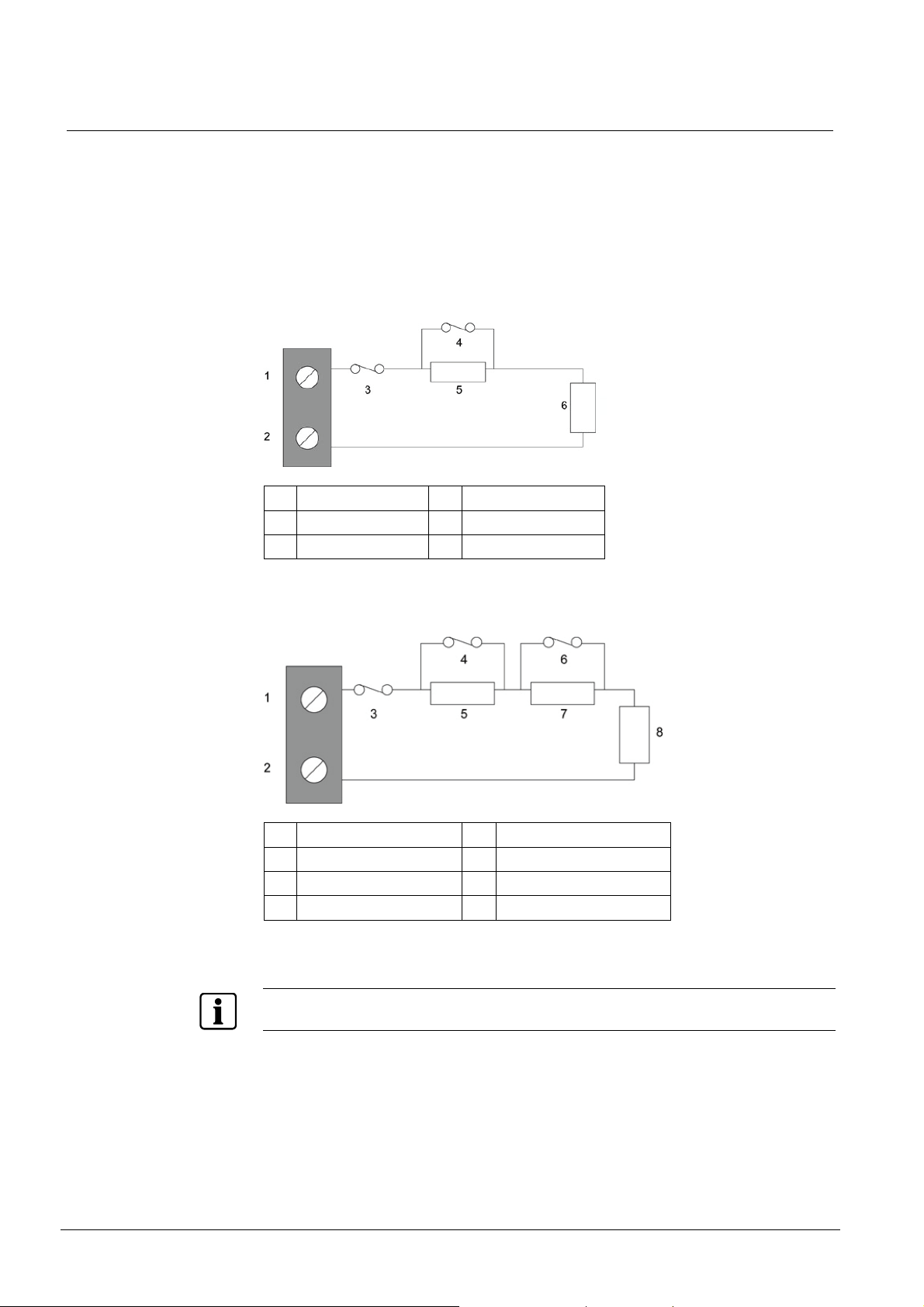
7.4 Wiring the Zone Inputs
The SPC Controller has eight on-board zone inputs. By default these inputs are
monitored using End of Line supervision. The installer can choose from:
z NEOL
z SEOL
z DEOL
z Anti-masking PIR
1 Input 1 4 Alarm
2 COM 5 Resistor
3 Tamper 6 4K7 EOL
Fig. 11 Default Configuration (DEOL 4K7)
1 Input 2 5 Alarm
2 COM 6 Anti-masking
3 Tamper 7 2K2
4 1K 8 EOL IK
Fig. 12 Anti-Masking PIR Configuration
Anti-Masking is only reported as "Alarm" type to ARC and if area or system is set.
30
Siemens Building Technologies
Fire Safety & Security Products 09.2008
 Loading...