

Page 1

SONOLINE G60 S Ultrasound Imaging System
System Reference
Siemens Medical Solutions USA, Inc. 10034099-ABS-001-01-01
Page 2

Page 3

SONOLINE G60 S
Ultrasound Imaging System
System Reference
Software Version 10
Siemens Medical Solutions USA, Inc.
Ultrasound Division
1230 Shorebird Way
Mountain View, CA 94043-1344
U.S.A.
(800) 498-7948
(650) 969-9112
CE Declaration
For systems affixed with a CE mark: This product is provided with a
CE marking in accordance with the regulations stated in Council Directive
93/42/EEC of June 14, 1993 concerning Medical Devices. Siemens Medical
Solutions USA, Inc., is certified by Notified Body 0123 to Annex II.3 – Full
Quality System.
Authorized EC Representative:
Siemens Aktiengesellschaft
Medical Solutions
Henkestraße 127
D-91052 Erlangen
Germany
©2006 Siemens Medical Solutions USA, Inc.
All Rights Reserved.
February 2006
Manuals distributed from the United States of America are printed in the
United States of America.
SONOLINE G60 S, Axius, DTI, fourSight, SieScape, MultiHertz, DIMAQ, microCase, ErgoDynamic, SynAps,
QuickSet, SuppleFlex, Crescendo, and Evolve Package are trademarks of Siemens Medical Solutions USA,
Inc.
Windows, CIDEX, CIDEX Plus, CIDEX OPA, Milton, Virkon, and Gigasept FF are registered trademarks of their
respective owners.
Siemens reserves the right to change system specifications at any time.
SYSTEM REFERENCE i
Page 4

ii SYSTEM REFERENCE
Page 5

Table of Contents
System Reference
Chapter Title Chapter Description
Chapter 1
Acoustic Output
Reference
Chapter 2
Accessories
and Options
Chapter 3
System Presets
Chapter 4
Documentation
and Storage
Chapter 5
DIMAQ-IP
Chapter 6
DICOM Connectivity
Option
Chapter 7
Network Export
Function
Chapter 8
Data Transmission
Specifications
Chapter 9
Obstetrical References
Chapter 10
Cardiac References
Chapter 11
Brochure
Note: Not all features and options described in this publication are available to all users.
Please check with your Siemens representative to determine the current availability of
features and options.
Acoustic output and MI/TI information.
Listing of the available configurations of the ultrasound system.
Instructions for using the options in the Preset Main Menu to customize
the system.
Information on how to use the ultrasound system with documentation and
storage devices, including procedures for storing and recalling system presets
and QuickSets.
Explanation of the integrated workstation option, including storage and
management of studies on the hard disk or CD.
Explanation of the Digital Imaging and Communications in Medicine (DICOM)
Connectivity option. This option works in conjunction with the DIMAQ-IP
integrated workstation to provide digital image transfer via a DICOM network
for both storage and printing
A description of setting up and using the network export function. This
function copies patient data to a password-protected shared folder on a
destination device (export host) for offline-analysis.
Guidelines for transmitting data from the ultrasound system through a serial
port to a personal computer (PC), printer, or other device.
Listing of authors and reference tables implemented for the Obstetric exam.
Listing of authors implemented for the Cardiac exam.
Medical Ultrasound Safety, American Institute of Ultrasound in Medicine.
SYSTEM REFERENCE iii
Page 6

iv SYSTEM REFERENCE
Page 7

About This Manual
The Instructions for Use consists of two volumes:
[1] Instructions for Use
The [1] Instructions for Use includes both a general overview and a
technical description of the ultrasound imaging system. This manual
contains detailed information on the safety and care of the ultrasound
system and its transducers. A chapter is dedicated to the description of
all system controls. The [1] Instructions for Use also includes the
procedures for system setup and beginning an exam.
[2] Instructions for Use
The [2] Instructions for Use includes procedures for acquiring and
optimizing images. This manual provides procedures for general and
exam-specific measurements and calculations.
The System Reference provides reference information for the ultrasound
imaging system.
The Electromagnetic Emissions and Immunity: Guidance and Manufacturer's
Declaration publication provides information regarding the electromagnetic
compatibility (EMC) testing of this system.
SYSTEM REFERENCE v
Page 8

Conventions
Conventions used throughout this manual are listed below. Take a moment
to familiarize yourself with these conventions.
Cross-References
This manual provides you information by topic. When additional information
exists within this or other manuals, a reference graphic and the name of the
book is provided in the right column. If the information exists within the
chapter, a cross-reference to the page number is listed. Otherwise,
information is referenced by chapter number.
System Presets
You can use the options and settings available in the system presets menu
to set up the ultrasound system with your preferences. Presets define the
configuration of the system software whenever you power on the system.
A complete listing of system presets is located in the System Reference.
Whenever a system preset is discussed in other chapters or in the User and
Reference Manuals, a graphic is provided in the right column.
The graphic identifies a preset option or setting in the system presets menu
that is available for you to customize your ultrasound system. The name of
the category on the menu containing the system preset is listed for
your convenience.
[1] Instructions for Use
Screen Saver Ch 1
Intended Use Ch 1
[2] Instructions for Use
Imaging Functions Ch A1
System Reference
Accessories
and Options Ch 2
F4
Default Settings
► Automatic Freeze
Response
vi SYSTEM REFERENCE
Page 9

Warnings, Cautions, and Notes
WARNING: Warnings are intended to alert you to the importance of following
the correct operating procedures where risk of injury to the patient or system
user exists.
Caution: Cautions are intended to alert you to the importance of following
correct operating procedures to prevent the risk of damage to the system.
Note: Notes contain information concerning the proper use of the system and/or correct
execution of a procedure.
Control Panel Keys, Controls, and LCD Selections
Keys and controls located on the control panel are identified by uppercase,
boldface type.
Example: Rotate the ZOOM control.
Function keys located on the keyboard are identified by the number of the
function key.
Example: Press the F4 key.
LCD keys are indicated by a (|) symbol with the name of the selection in
boldface type.
Example: Press |Next to access the second page of LCD selections.
SYSTEM REFERENCE vii
Page 10

Selection of On-Screen Objects
The SET key on the control panel functions as a point-and-select device
(similar to a computer mouse) when used with the trackball. To select an
on-screen object such as a button or a T symbol, roll the trackball to
position the pointer (cursor) on the object and then press the SET key on
the control panel.
In this manual, the term "select" or "click" describe the trackball and SET key
action required to select an on-screen object. In the example below, phrases
A, B, C, and D are equivalent actions.
A. Roll the trackball to the Search button and then press the SET key.
B. Select the Search button.
C. Click the Search button.
D. Click Search.
Special Terms and Menu Options
Special terms are indicated in boldface italics and are accompanied by a brief
description on their first use in the manual.
Example: Provides on-screen anatomical graphics of
indicate the anatomy under evaluation.
Within a procedure, options in the system presets are identified in text as
boldface type.
Example: Highlight the Keyboard – Annotation option.
pictograms
that
viii SYSTEM REFERENCE
Page 11

1 Acoustic Output Reference
Transducer Technical Data and Acoustic Output............................................ 3
Display Resolution and Measurement Accuracy ........................................... 3
Default Displayed MI and TI Values by Transducer .......................................4
Transducers and Intended Applications......................................................... 5
IEC 61157 Acoustic Output Reporting .............................................................. 6
Track 3, FDA 510(k) Acoustic Output Reporting............................................ 15
Summary Table for Acoustic Output ........................................................... 15
Definitions ................................................................................................... 16
SYSTEM REFERENCE 1 - 1
Page 12

1 Acoustic Output Reference
1 - 2 SYSTEM REFERENCE
Page 13

1 Acoustic Output Reference
γ
Transducer Technical Data and Acoustic Output
Display Resolution and Measurement Accuracy
For any transducer capable of exceeding a mechanical or thermal index
value of 1.0, the ultrasound imaging system displays indices starting from
0.4. The resolution of the display is 0.1 for all displayed values of MI. For all
TI values, the resolution of the display is 0.2.
It is important to note that displayed indices are obtained through
measurement, and are subject to measurement errors. Specific
measurement uncertainties for acoustic power, pressure, and center
frequency are 5.4%, 8.5%, and 2.1% respectively. Measurement precision
for ultrasonic power, peak rarefactional pressure, and center frequency from
a standard test transducer/driver combination is 8.2%, 4.6%, and 1.1%
respectively. The reported values assume 90% population (P ) at 90%
confidence level (
1998 AIUM/NEMA document entitled Standard for Real-Time Display of
Thermal and Mechanical Acoustic Output Indices on Diagnostic Ultrasound
Equipment – Revision 1 (also known as the Output Display Standard).
).Definitions for these parameters can be found in the
SYSTEM REFERENCE 1 - 3
Page 14

1 Acoustic Output Reference
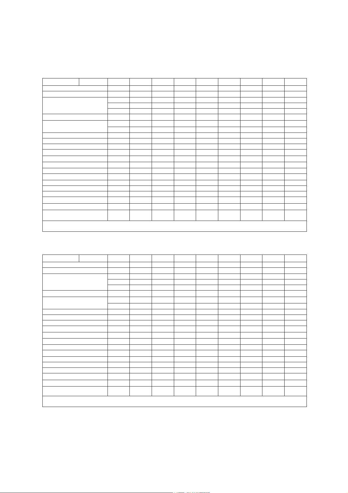
Default Displayed MI and TI Values by Transducer
(Per transducer/mode that exceeds default MI or TI value of 1.0)
Note: For SONOVISTA systems only:
The 3.5C55S transducer is the equivalent of the C6-2 transducer.
The 3D-ABD transducer is the equivalent of the C6F3 transducer.
The 6.5EV13 transducer is the equivalent of the EV9-4 transducer.
Mode
B M PwD Color cwD
Transducer
P4-2 1.0 1.0 1.0 3.2 2.6
P9-4 1.6 1.0 1.8 2.0 1.2 2.0
L10-5 1.0
7.5L70 1.2
5.0L45 1.2
VF13-5 1.1 1.1 1.2
VF13-5SP 1.0 1.0 1.8
CH5-2 1.4 1.4 2.4
C6-2 1.0 1.0 1.8
C6-3 3D/C6F3
5.0C50+ 1.6
C8-5 1.0
BE9-4 1.0 1.0
EC9-4
EV9-4 1.0 1.0 1.0
CW21 3.0
CW51 1.8
MI TI MI TI MI TI MI TI MI TI
1
Not available for SONOVISTA systems
1 - 4 SYSTEM REFERENCE
Page 15

1 Acoustic Output Reference
Transducers and Intended Applications
Only the following transducers from Siemens are compatible with the G60 S ultrasound
imaging system:
Note: For SONOVISTA systems only:
The 3.5C55S transducer is the equivalent of the C6-2 transducer.
The 3D-ABD transducer is the equivalent of the C6F3 transducer.
The 6.5EV13 transducer is the equivalent of the EV9-4 transducer.
Note: Certain transducers may require features not available on your system. Refer to the
Accessories and Options chapter of the System Reference for a list of system-specific
features and options, including transducers.
EMC Note: Operating the transducer in close proximity to sources of strong
electromagnetic fields, such as radio transmitter stations or similar installations, may lead
to temporary degradation or interference visible on the monitor screen. A lightening of
image background may be noticed while visualizing hypoechoic structures, or color
spectral interference, or jitter, or horizontal lines in the image screen may occur. The
transducer and the system have been designed and tested to withstand such interference
and will not be permanently damaged. Refer to the Electromagnetic Emissions and
Immunity Guidence and Manufacturer's Declaration.
TRANSDUCER
NAME
CH5-2
C6-2
C6-3 3D/C6F3
C8-5
5.0C50+
BE9-4
EC9-4
EV9-4
5.0L45
7.5L70
L10-5
VF13-5
VF13-5SP
P9-4
P4-2
CW21
Error! Bookmark
CW5
not defined.
OPERATING
FREQUENCY MODES OF OPERATION INTENDED APPLICATIONS
CURVED AND LINEAR ARRAY TRANSDUCERS
2 – 5 MHz B, C, M, PW
2 – 6 MHz B, C, M, PW
2 – 5 MHz B, C, M, PW
5 – 8 MHz B, C, M, PW
3.5 – 7.5 MHz B, C, M, PW
TBD – TBD
MHz
4 – 9 MHz B, C, M, PW
4 – 8 MHz B, C, M, PW
3.6 – 6.0 MHz B, C, M, PW
5 – 10 MHz B, C, M, PW
5 – 10 MHz B, C, M, PW
5 – 13 MHz B, C, M, PW
5 – 13 MHz B, C, M, PW
4 – 9 MHz B, C, M, PW, CW
2 – 4 MHz B, C, M, PW, CW
2 MHz CW
5 MHz CW
B, C, M, PW
PHASED ARRAY TRANSDUCERS
CONTINUOUS WAVE TRANSDUCERS
Abdomen, Renal, Obstetrics, Gynecology,
Peripheral Vascular
Abdomen, Renal, Obstetrics, Gynecology,
Peripheral Vascular
Abdomen, Obstetrics, Gynecology, Pelvic
Neonatal Cephalic, Neonatal Abdomen
Abdomen, Obstetrics, Gynecology, Pediatric
Endorectal, Endovaginal
Prostate, Early Obstetrics, Gynecology
Early Obstetrics, Gynecology
Peripheral Vascular, Cerebrovascular,
Musculoskeletal, Breast, Thyroid
Breast, Thyroid,
Orthopedics, Musculoskeletal
Thyroid, Breast, Testis, Cerebrovascular,
Orthopedics, Musculoskeletal
Breast, Testis, Thyroid,
Superficial, Musculoskeletal
Intraoperative Abdominal, Intraoperative
Neurological, Pediatric, Small Organ,
Peripheral Vessel, Musculoskeletal,
Superficial Musculoskeletal
Pediatric, Cardiology, Abdomen,
Neonatal Cephalic
Adult Cardiology, Abdomen, Renal,
Transcranial Imaging
Adult Cardiology
Vascular
1
Not available for SONOVISTA systems
SYSTEM REFERENCE 1 - 5
Page 16
1 Acoustic Output Reference
IEC 61157 Acoustic Output Reporting
Acoustic output information for the G60 S ultrasound imaging system.
Phased Array Transducer. Type: P4-2
Manufacturer: Siemens Medical Solutions USA, Inc., Ultrasound Group
Parameter Mode Bp Bi Mp Mi (B+C)p (M+C)i Dp Di CwD
p_ (MPa)
I
(mW/cm2) 540 590 550 560 590 1600 1200 1600 1200
spta
System settings 3.0 MHz 2.1 MHz 3.0 MHz 2.1 MHz
Focus in mm 49 49 49 49 71 84 100 84 60
Output in dB 0 0 0 0 0 0 0 0 0
Ip (mm) 39 36 39 36 56 66 70 67 41
W
(II) (mm) 2.2 2.6 2.2 2.6 2.9 3.3 4.4 2.9 3.8
pb6
(⊥) (mm)
prr (kHz)
srr (Hz)
Output beam dimensions (mm) 14 x 13 14 x 13 14 x 13 14 x 13 20 x 13 20 x 13 20 x 13 20 x 13 9.3 x 13
f
(MHz) 2.5 2.1 2.5 2.1 2.1 2.6 2.1 2.6 2.5
awf
APF a (%)
AIF b (%)
Maximum power (mW) 340 410 51 61 69 250 250 190 150
I
(mW/cm2) 180 220 27 33 27 96 98 73 130
ob
Power-up mode B B B B B B B B B
Initialization mode n/a n/a n/a n/a n/a n/a n/a n/a n/a
Acoustic output freeze Yes Yes Yes Yes Yes Yes Yes Yes Yes
Itt (mm) n/a n/a n/a n/a n/a n/a n/a n/a n/a
Its (mm) contact contact contact contact contact contact contact contact Contact
Inclusive modes - - B+M B+M M+C,
a Acoustic power-up fraction
b Acoustic initialization fraction
Acoustic output information for the G60 S ultrasound imaging system.
Phased Array Transducer. Type: P9-4
Manufacturer: Siemens Medical Solutions USA, Inc., Ultrasound Group
Parameter Mode Bp Bi Mp Mi (M+C)p (M+C)i Dp Di CwD
p_ (MPa)
I
(mW/cm2) 88 190 180 260 920 1800 1300 1900 1600
spta
System settings 8.0 MHz 4.0 MHz 8.0 MHz 4.0 MHz
Focus in mm 19 35 19 35 35 50 42 50 29
Output in dB 0 0 0 0 0 0 0 0 0
Ip (mm) 13 26 13 26 31 43 34 43 33
W
(II) (mm) 1.0 1.9 1.0 1.9 1.3 1.6 1.7 1.6 2.2
pb6
(⊥) (mm)
prr (kHz)
srr (Hz)
Output beam dimensions (mm) 4.6 x 8.0 6.0 x 8.0 4.6 x 8.0 6.0 x 8.0 6.7 x 8.0 7.7 x 8.0 7.7 x 8.0 7.7 x 8.0 3.6 x 8.0
f
(MHz) 5.5 4.2 5.5 4.2 5.3 5.3 5.3 5.3 5.1
awf
APF a (%)
AIF b (%)
Maximum power (mW) 59 79 13 18 26 66 50 69 74
I
(mW/cm2) 160 160 36 37 48 110 81 110 260
ob
Power-up mode B B B B B B B B B
Initialization mode n/a n/a n/a n/a n/a n/a n/a n/a n/a
Acoustic output freeze Yes Yes Yes Yes Yes Yes Yes Yes Yes
Itt (mm) n/a n/a n/a n/a n/a n/a n/a n/a n/a
Its (mm) contact contact contact contact contact contact contact contact contact
Inclusive modes - - B+M B+M B+C,B+C
a Acoustic power-up fraction
b Acoustic initialization fraction
Acoustic output information is presented according to the recommendations of
the International Electrotechnical Commission (IEC) as expressed in IEC 61157.
3.3 2.6 3.3 2.6 2.9 1.8 2.4 1.2 0.17
3.6 3.6 3.6 3.6 3.4 4.0 4.1 3.5 2.9
4.5 4.5 1.0 1.0 1.0 4.1 1.3 15.2 -
118 118 - - - - - - -
n/a n/a n/a n/a n/a n/a n/a n/a n/a
n/a n/a n/a n/a n/a n/a n/a n/a n/a
B+C+D
3.7 2.5 3.7 2.5 3.5 1.7 2.8 1.9 0.19
5.9 2.9 5.9 2.9 1.9 1.9 1.9 1.9 1.8
3.0 3.0 1.0 1.0 1.9 12.5 1.3 5.8 -
78 78 - - - - - - -
n/a n/a n/a n/a n/a n/a n/a n/a n/a
n/a n/a n/a n/a n/a n/a n/a n/a n/a
+D
B+C,
B+C+D
B+C,B+C
+D
B+D,
B+M+D
B+D,B+M
+D
B+D,
B+M+D
B+D,B+M
+D
-
-
1 - 6 SYSTEM REFERENCE
Page 17
1 Acoustic Output Reference
Acoustic output information for the G60 S ultrasound imaging system. Linear Array
Transducer. Type: L10-5
Manufacturer: Siemens Medical Solutions USA, Inc., Ultrasound Group
Parameter Mode Bp Bi Mp Mi (B+C)p (M+C)i Dp Di
p_ (MPa)
I
(mW/cm2) 64 99 100 140 140 1300 820 1300
spta
System settings 10.0 MHz 6.5 MHz 10.0 MHz 6.5 MHz
Focus in mm 26 26 26 26 26 26 26 26
Output in dB 0 0 0 0 0 0 0 0
Ip (mm) 19 20 19 20 19 20 19 20
W
(II) (mm) 1.1 1.3 1.1 1.3 1.2 1.1 1.2 1.1
pb6
(⊥) (mm)
prr (kHz)
srr (Hz)
Output beam dimensions (mm) 5.7 x 5.0 5.7 x 5.0 5.7 x 5.0 5.7 x 5.0 5.7 x 5.0 5.7 x 5.0 5.7 x 5.0 5.7 x 5.0
f
(MHz) 5.7 5.6 5.7 5.6 5.2 7.0 5.2 7.0
awf
APF a (%)
AIF b (%)
Maximum power (mW) 12 24 1.8 3.5 3.2 19 19 18
I
(mW/cm2) 40 80 6.1 12 11 65 65 63
ob
Power-up mode B B B B B B B B
Initialization mode n/a n/a n/a n/a n/a n/a n/a n/a
Acoustic output freeze Yes Yes Yes Yes Yes Yes Yes Yes
Itt (mm) n/a n/a n/a n/a n/a n/a n/a n/a
Its (mm) contact contact contact contact contact contact contact contact
Inclusive modes - - B+M B+M M+C,
a Acoustic power-up fraction
b Acoustic initialization fraction
2.4 2.1 2.4 2.1 3.3 1.8 2.7 1.4
1.3 1.7 1.3 1.7 1.6 1.1 1.6 1.1
4.5 4.5 1.0 1.0 1.3 7.6 1.3 15.2
94 94 - - - - - -
n/a n/a n/a n/a n/a n/a n/a n/a
n/a n/a n/a n/a n/a n/a n/a n/a
B+C+D
B+C,
B+C+D
B+D,
B+M+D
B+D,
B+M+D
Acoustic output information for the G60 S ultrasound imaging system. Linear Array
Transducer. Type: 7.5L70
Manufacturer: Siemens Medical Solutions USA, Inc., Ultrasound Group
Parameter Mode Bp Bi Mp Mi (M+C)p (M+C)i Dp Di
p_ (MPa)
I
(mW/cm2) 58 120 150 250 700 1500 710 1500
spta
System settings 6.0 MHz 7.5 MHz 6.0 MHz 7.5 MHz
Focus in mm 20 25 20 25 25 30 17 30
Output in dB 0 0 0 0 0 0 0 0
Ip (mm) 13 16 13 16 18 23 14 23
(II) (mm) 1.1 1.5 1.1 1.5 1.1 1.1 1.3 1.1
W
pb6
(⊥) (mm)
prr (kHz)
srr (Hz)
Output beam dimensions (mm) 5.0 x 5.0 6.5 x 5.0 5.0 x 5.0 6.5 x 5.0 6.5 x 5.0 7.9 x 5.0 4.3 x 5.0 7.9 x 5.0
f
(MHz) 6.4 6.0 6.4 6.0 7.0 7.0 5.2 7.0
awf
APF a (%)
AIF b (%)
Maximum power (mW) 18 33 2.6 4.9 9.3 23 13 23
I
(mW/cm2) 71 100 10 15 29 57 61 57
ob
Power-up mode B B B B B B B B
Initialization mode n/a n/a n/a n/a n/a n/a n/a n/a
Acoustic output freeze Yes Yes Yes Yes Yes Yes Yes Yes
Itt (mm) n/a n/a n/a n/a n/a n/a n/a n/a
Its (mm) contact contact contact contact contact contact contact contact
Inclusive modes - - B+M B+M B+C,
a Acoustic power-up fraction
b Acoustic initialization fraction
3.5 2.9 3.5 2.9 3.3 1.8 3.0 1.8
1.4 1.1 1.4 1.1 1.0 1.1 1.2 1.1
4.5 4.5 1.0 1.0 1.3 8.7 1.3 10
94 94 - - - - - -
n/a n/a n/a n/a n/a n/a n/a n/a
n/a n/a n/a n/a n/a n/a n/a n/a
B+C+D
B+C,
B+C+D
B+D,
B+M+D
B+D,
B+M+D
Acoustic output information is presented according to the recommendations of
the International Electrotechnical Commission (IEC) as expressed in IEC 61157.
SYSTEM REFERENCE 1 - 7
Page 18
1 Acoustic Output Reference
Acoustic output information for the G60 S ultrasound imaging system. Linear Array
Transducer. Type: VF13-5
Manufacturer: Siemens Medical Solutions USA, Inc., Ultrasound Group
Parameter Mode Bp Bi Mp Mi (B+C)p (M+C)i Dp Di
p_ (MPa)
I
(mW/cm2) 81 94 130 170 110 990 520 1000
spta
System settings 12.0 MHz 8.0 MHz 12.0 MHz 8.0 MHz
Focus in mm 15 12 15 12 12 21 5.0 21
Output in dB 0 0 0 0 0 0 0 0
Ip (mm) 7.0 6.0 7.0 6.0 6.0 13 4.0 13
W
(II) (mm) 1.1 1.0 1.1 1.0 1.0 1.1 1.1 1.1
pb6
(⊥) (mm)
prr (kHz)
srr (Hz)
Output beam dimensions (mm) 4.0 x 2.5 3.2 x 2.5 4.0 x 2.5 3.2 x 2.5 3.2 x 2.5 5.6 x 2.5 1.6 x 2.5 5.6 x 2.5
f
(MHz) 7.5 7.3 7.5 7.3 7.0 7.0 7.0 7.0
awf
APF a (%)
AIF b (%)
Maximum power (mW) 13 15 1.9 2.2 1.4 22 8.3 22
I
(mW/cm2) 130 190 19 27 17 160 210 160
ob
Power-up mode B B B B B B B B
Initialization mode n/a n/a n/a n/a n/a n/a n/a n/a
Acoustic output freeze Yes Yes Yes Yes Yes Yes Yes Yes
Itt (mm) n/a n/a n/a n/a n/a n/a n/a n/a
Its (mm) contact contact contact contact contact contact contact contact
Inclusive modes - - B+M B+M M+C,
a Acoustic power-up fraction
b Acoustic initialization fraction
3.7 3.0 3.7 3.0 3.6 1.8 3.4 1.4
1.1 1.1 1.1 1.1 1.1 1.7 1.3 1.7
4.5 4.5 1.0 1.0 1.0 6.6 1.3 15.2
94 94 - - - - - -
n/a n/a n/a n/a n/a n/a n/a n/a
n/a n/a n/a n/a n/a n/a n/a n/a
B+C+D
B+C,
B+C+D
B+D,
B+M+D
B+D,
B+M+D
Acoustic output information for the G60 S ultrasound imaging system. Linear Array
Transducer. Type: VF13-5SP
Manufacturer: Siemens Medical Solutions USA, Inc., Ultrasound Group
Parameter Mode Bp Bi Mp Mi (B+C)p (M+C)i Dp Di
p_ (MPa)
I
(mW/cm2) 81 130 130 220 110 990 520 1000
spta
System settings 12.0 MHz 8.0 MHz 12.0 MHz 8.0 MHz
Focus in mm 15 12 15 12 12 21 5.0 21
Output in dB 0 0 0 0 0 0 0 0
Ip (mm) 7.0 6.0 7.0 6.0 6.0 13 4.0 13
W
(II) (mm) 1.1 1.0 1.1 1.0 1.0 1.1 1.1 1.1
pb6
(⊥) (mm)
prr (kHz)
srr (Hz)
Output beam dimensions (mm) 4.0 x 2.5 3.2 x 2.5 4.0 x 2.5 3.2 x 2.5 3.2 x 2.5 5.6 x 2.5 1.6 x 2.5 5.6 x 2.5
f
(MHz) 7.5 7.3 7.5 7.3 7.0 7.0 7.0 7.0
awf
APF a (%)
AIF b (%)
Maximum power (mW) 13 20 1.9 3.0 1.4 22 8.3 22
I
(mW/cm2) 130 250 19 37 17 160 210 160
ob
Power-up mode B B B B B B B B
Initialization mode n/a n/a n/a n/a n/a n/a n/a n/a
Acoustic output freeze Yes Yes Yes Yes Yes Yes Yes Yes
Itt (mm) n/a n/a n/a n/a n/a n/a n/a n/a
Its (mm) contact contact contact contact contact contact contact contact
Inclusive modes - - B+M B+M M+C,
a Acoustic power-up fraction
b Acoustic initialization fraction
3.7 3.4 3.7 3.4 3.6 1.8 3.4 1.4
1.1 1.1 1.1 1.1 1.1 1.7 1.3 1.7
4.5 4.5 1.0 1.0 1.0 6.6 1.3 15.2
94 94 - - - - - -
n/a n/a n/a n/a n/a n/a n/a n/a
n/a n/a n/a n/a n/a n/a n/a n/a
B+C+D
B+C,
B+C+D
B+D,
B+M+D
B+D,
B+M+D
Acoustic output information is presented according to the recommendations of
the International Electrotechnical Commission (IEC) as expressed in IEC 61157.
1 - 8 SYSTEM REFERENCE
Page 19

1 Acoustic Output Reference
Acoustic output information for the G60 S ultrasound imaging system. Curved
Array Transducer. Type: 5.0L45
Manufacturer: Siemens Medical Solutions USA, Inc., Ultrasound Group
Parameter Mode Bp Bi Mp Mi (M+C)p (M+C)i Dp Di
p_ (MPa)
I
(mW/cm2) 170 240 210 230 900 1500 900 1300
spta
System settings 5.0 MHz 4.0 MHz 5.0 MHz 4.0 MHz
Focus in mm 29 35 29 35 29 42 29 42
Output in dB 0 0 0 0 0 0 0 0
Ip (mm) 20 23 20 23 23 30 23 30
W
(II) (mm) 1.5 1.8 1.5 1.8 1.3 1.7 1.3 1.7
pb6
(⊥) (mm)
prr (kHz)
srr (Hz)
Output beam dimensions (mm) 6.8 x 7.0 8.1 x 7.0 6.8 x 7.0 8.1 x 7.0 6.8 x 7.0 9.3 x 7.0 6.8 x 7.0 9.3 x 7.0
f
(MHz) 5.1 3.9 5.1 3.9 5.2 5.2 5.2 5.2
awf
APF a (%)
AIF b (%)
Maximum power (mW) 36 52 5.4 7.8 15 42 15 38
I
(mW/cm2) 76 93 11 14 31 65 31 59
ob
Power-up mode B B B B B B B B
Initialization mode n/a n/a n/a n/a n/a n/a n/a n/a
Acoustic output freeze Yes Yes Yes Yes Yes Yes Yes Yes
Itt (mm) n/a n/a n/a n/a n/a n/a n/a n/a
Its (mm) contact contact contact contact contact contact contact contact
Inclusive modes - - B+M B+M B+C,
a Acoustic power-up fraction
b Acoustic initialization fraction
3.2 2.9 3.2 2.9 3.0 1.6 3.0 1.5
1.5 1.5 1.5 1.5 1.1 1.4 1.1 1.4
4.5 4.5 1.0 1.0 1.3 6.9 1.3 8.6
136 136 - - - - - -
n/a n/a n/a n/a n/a n/a n/a n/a
n/a n/a n/a n/a n/a n/a n/a n/a
B+C+D
B+C,
B+C+D
B+D,
B+M+D
B+D,
B+M+D
Acoustic output information for the G60 S ultrasound imaging system. Curved
Array Transducer. Type: C6-2
Manufacturer: Siemens Medical Solutions USA, Inc., Ultrasound Group
Parameter Mode Bp Bi Mp Mi (M+C)p (M+C)i Dp Di
p_ (MPa)
I
(mW/cm2) 100 100 180 180 720 1700 610 1200
spta
System settings 5.0 MHz 5.0 MHz 5.0 MHz 5.0 MHz
Focus in mm 73 73 73 73 86 73 86 73
Output in dB 0 0 0 0 0 0 0 0
Ip (mm) 44 44 44 44 57 50 57 50
W
(II) (mm) 2.9 2.9 2.9 2.9 3.0 2.7 3.0 2.7
pb6
(⊥) (mm)
prr (kHz)
srr (Hz)
Output beam dimensions (mm) 11 x 11 11 x 11 11 x 11 11 x 11 13 x 11 11 x 11 13 x 11 11 x 11
f
(MHz) 3.3 3.3 3.3 3.3 3.5 3.5 3.5 3.5
awf
APF a (%)
AIF b (%)
Maximum power (mW) 210 210 32 32 79 190 66 130
I
(mW/cm2) 180 180 27 27 55 160 47 110
ob
Power-up mode B B B B B B B B
Initialization mode n/a n/a n/a n/a n/a n/a n/a n/a
Acoustic output freeze Yes Yes Yes Yes Yes Yes Yes Yes
Itt (mm) n/a n/a n/a n/a n/a n/a n/a n/a
Its (mm) contact contact contact contact contact contact contact contact
Inclusive modes - - B+M B+M B+C,
a Acoustic power-up fraction
b Acoustic initialization fraction
2.7 2.7 2.7 2.7 2.6 1.5 2.4 1.2
5.1 5.1 5.1 5.1 3.1 3.4 3.1 3.4
4.5 4.5 1.0 1.0 1.3 7.6 1.3 8.6
94 94 - - - - - -
n/a n/a n/a n/a n/a n/a n/a n/a
n/a n/a n/a n/a n/a n/a n/a n/a
B+C+D
B+C,
B+C+D
B+D,
B+M+D
B+D,
B+M+D
Acoustic output information is presented according to the recommendations of
the International Electrotechnical Commission (IEC) as expressed in IEC 61157.
SYSTEM REFERENCE 1 - 9
Page 20
1 Acoustic Output Reference
Acoustic output information for the G60 S ultrasound imaging system. Curved
Array Transducer. Type: CH5-2
Manufacturer: Siemens Medical Solutions USA, Inc., Ultrasound Group
Parameter Mode Bp Bi Mp Mi (M+C)p (M+C)i Dp Di CwD
p_ (MPa)
I
(mW/cm2) 140 170 200 220 710 1300 820 1300 140
spta
System settings 5.0 MHz 4.0 MHz 5.0 MHz 4.0 MHz 5.0 MHz
Focus in mm 73 73 73 73 73 86 86 86 73
Output in dB 0 0 0 0 0 0 0 0 0
Ip (mm) 50 50 50 50 55 61 61 61 50
W
(II) (mm) 3.2 3.6 3.2 3.6 2.8 3.2 3.2 3.2 3.2
pb6
(⊥) (mm)
prr (kHz)
srr (Hz)
Output beam dimensions (mm) 13 x 14 13 x 14 13 x 14 13 x 14 13 x 14 16 x 14 13 x 14 16 x 14 13 x 14
f
(MHz) 2.7 2.1 2.7 2.1 2.6 2.6 2.6 2.6 2.7
awf
APF a (%)
AIF b (%)
Maximum power (mW) 190 240 29 35 83 180 110 170 190
I
(mW/cm2) 100 130 15 19 44 80 48 73 100
ob
Power-up mode B B B B B B B B B
Initialization mode n/a n/a n/a n/a n/a n/a n/a n/a n/a
Acoustic output freeze Yes Yes Yes Yes Yes Yes Yes Yes Yes
Itt (mm) n/a n/a n/a n/a n/a n/a n/a n/a n/a
Its (mm) contact contact contact contact contact contact contact contact contact
Inclusive modes - - B+M B+M B+C,B+C
a Acoustic power-up fraction
b Acoustic initialization fraction
2.3 1.5 2.3 1.5 2.3 1.7 2.6 1.8 2.3
3.8 3.9 3.8 3.9 3.5 3.5 3.5 3.5 3.8
4.5 4.5 1.0 1.0 1.0 4.4 1.4 4.1 4.5
155 155 - - - - - - 155
n/a n/a n/a n/a n/a n/a n/a n/a n/a
n/a n/a n/a n/a n/a n/a n/a n/a n/a
+D
B+C,B+C
+D
B+D,B+M
+D
B+D,B+M
+D
-
Acoustic output information for the G60 S ultrasound imaging system. Curved
Array Transducer. Type: C6-3 3D/C6F3
Manufacturer: Siemens Medical Solutions USA, Inc., Ultrasound Group
Parameter Mode Bp Bi Mp Mi (M+C)p (M+C)i Dp Di
p_ (MPa)
I
(mW/cm2) 19 21 120 140 470 860 500 820
spta
System settings 3.5 MHz 3.5 MHz 3.5 MHz 3.5 MHz
Focus in mm 73 73 73 73 51 61 51 61
Output in dB 0 0 0 0 0 0 0 0
Ip (mm) 52 53 52 53 46 54 46 54
W
(II) (mm) 2.6 2.7 2.6 2.7 2.3 2.3 2.3 2.3
pb6
(⊥) (mm)
prr (kHz)
srr (Hz)
Output beam dimensions (mm) 15 x 11 15 x 11 15 x 11 15 x 11 15 x 11 13 x 11 12 x 11 13 x 11
f
(MHz) 3.1 3.1 3.1 3.1 3.5 3.5 3.5 3.5
awf
APF a (%)
AIF b (%)
Maximum power (mW) 73 91 11 13 39 70 42 67
I
(mW/cm2) 44 54 6.5 8.0 30 49 32 46
ob
Power-up mode B B B B B B B B
Initialization mode n/a n/a n/a n/a n/a n/a n/a n/a
Acoustic output freeze Yes Yes Yes Yes Yes Yes Yes Yes
Itt (mm) n/a n/a n/a n/a n/a n/a n/a n/a
Its (mm) contact contact contact contact contact contact contact contact
Inclusive modes - - B+M B+M B+C,
a Acoustic power-up fraction
b Acoustic initialization fraction
2.1 2.0 2.1 2.0 1.8 1.4 1.9 1.4
3.1 3.1 3.1 3.1 3.0 3.0 3.0 3.0
4.5 4.5 1.0 1.0 1.3 3.3 1.3 3.3
47 47 - - - - - -
n/a n/a n/a n/a n/a n/a n/a n/a
n/a n/a n/a n/a n/a n/a n/a n/a
B+C+D
B+C,
B+C+D
B+D,
B+M+D
B+D,
B+M+D
Acoustic output information is presented according to the recommendations of
the International Electrotechnical Commission (IEC) as expressed in IEC 61157.
1 - 10 SYSTEM REFERENCE
Page 21

1 Acoustic Output Reference
Acoustic output information for the G60 S ultrasound imaging system. Curved
Array Transducer. Type: 5.0C50+
Manufacturer: Siemens Medical Solutions USA, Inc., Ultrasound Group
Parameter Mode Bp Bi Mp Mi (M+C)p (M+C)i Dp Di
p_ (MPa)
I
(mW/cm2) 100 100 250 250 1200 2800 1200 2700
spta
System settings 3.5 MHz 3.5 MHz 3.5 MHz 3.5 MHz
Focus in mm 51 51 51 51 61 61 61 61
Output in dB 0 0 0 0 0 0 0 0
Ip (mm) 44 44 44 44 49 49 49 51
W
(II) (mm) 1.9 1.9 1.9 1.9 2.2 2.2 2.2 1.5
pb6
(⊥) (mm)
prr (kHz)
srr (Hz)
Output beam dimensions (mm) 12 x 11 12 x 11 12 x 11 12 x 11 13 x 11 13 x 11 13 x 11 13 x 11
f
(MHz) 4.0 4.0 4.0 4.0 3.5 5.2 3.5 5.2
awf
APF a (%)
AIF b (%)
Maximum power (mW) 86 86 13 13 65 160 67 79
I
(mW/cm2) 102 102 15 15 44 110 45 53
ob
Power-up mode B B B B B B B B
Initialization mode n/a n/a n/a n/a n/a n/a n/a n/a
Acoustic output freeze Yes Yes Yes Yes Yes Yes Yes Yes
Itt (mm) n/a n/a n/a n/a n/a n/a n/a n/a
Its (mm) contact contact contact contact contact contact contact contact
Inclusive modes - - B+M B+M B+C,
a Acoustic power-up fraction
b Acoustic initialization fraction
3.0 3.0 3.0 3.0 2.8 1.7 2.9 1.7
2.3 2.3 2.3 2.3 2.2 2.2 2.2 1.6
4.5 4.5 1.0 1.0 1.3 12.5 1.3 12.5
94 94 - - - - - -
n/a n/a n/a n/a n/a n/a n/a n/a
n/a n/a n/a n/a n/a n/a n/a n/a
B+C+D
B+C,
B+C+D
B+D,
B+M+D
B+D,
B+M+D
Acoustic output information for the G60 S ultrasound imaging system. Curved
Array Transducer. Type: C8-5
Manufacturer: Siemens Medical Solutions USA, Inc., Ultrasound Group
Parameter Mode Bp Bi Mp Mi (M+C)p (M+C)i Dp Di
p_ (MPa)
I
(mW/cm2) 150 150 290 290 780 1300 880 1400
spta
System settings 5.0 MHz 5.0 MHz 5.0 MHz 5.0 MHz
Focus in mm 23 23 23 23 19 40 27 40
Output in dB 0 0 0 0 0 0 0 0
Ip (mm) 15 15 15 15 16 30 20 30
W
(II) (mm) 1.4 1.4 1.4 1.4 1.2 1.3 1.2 1.3
pb6
(⊥) (mm)
prr (kHz)
srr (Hz)
Output beam dimensions (mm) 6.2 x 5.0 6.2 x 5.0 6.2 x 5.0 6.2 x 5.0 5.2 x 5.0 10 x 5.0 7.1 x 5.0 10 x 5.0
f
(MHz) 4.7 4.7 4.7 4.7 5.2 5.2 5.2 5.2
awf
APF a (%)
AIF b (%)
Maximum power (mW) 40 40 5.9 5.9 13 44 16 48
I
(mW/cm2) 130 130 19 19 49 85 45 92
ob
Power-up mode B B B B B B B B
Initialization mode n/a n/a n/a n/a n/a n/a n/a n/a
Acoustic output freeze Yes Yes Yes Yes Yes Yes Yes Yes
Itt (mm) n/a n/a n/a n/a n/a n/a n/a n/a
Its (mm) contact contact contact contact contact contact contact contact
Inclusive modes - - B+M B+M B+C,
a Acoustic power-up fraction
b Acoustic initialization fraction
3.4 3.4 3.4 3.4 3.0 1.4 3.0 1.3
1.3 1.3 1.3 1.3 1.1 2.2 1.4 2.2
4.5 4.5 1.0 1.0 1.3 10.4 1.3 16.7
110 110 - - - - - -
n/a n/a n/a n/a n/a n/a n/a n/a
n/a n/a n/a n/a n/a n/a n/a n/a
B+C+D
B+C,
B+C+D
B+D,
B+M+D
B+D,
B+M+D
Acoustic output information is presented according to the recommendations of
the International Electrotechnical Commission (IEC) as expressed in IEC 61157.
SYSTEM REFERENCE 1 - 11
Page 22

1 Acoustic Output Reference
Acoustic output information for the G60 S ultrasound imaging system. Curved
Array Transducer. Type: EC9-4
Manufacturer: Siemens Medical Solutions USA, Inc., Ultrasound Group
Parameter Mode Bp Bi Mp Mi (M+C)p (M+C)i Dp Di
p_ (MPa)
I
(mW/cm2) 85 100 140 170 830 1200 860 1200
spta
System settings 6.5 MHz 4.2 MHz 6.5 MHz 4.2 MHz
Focus in mm 21 21 21 21 26 37 26 21
Output in dB 0 0 0 0 0 0 0 0
Ip (mm) 15 15 15 15 18 23 18 18
W
(II) (mm) 1.6 1.5 1.6 1.5 1.6 2.3 1.6 1.1
pb6
(⊥) (mm)
prr (kHz)
srr (Hz)
Output beam dimensions (mm) 5.3 x 5.0 5.3 x 5.0 5.3 x 5.0 5.3 x 5.0 5.7 x 5.0 7.4 x 5.0 5.7 x 5.0 5.3 x 5.0
f
(MHz) 5.0 4.8 5.0 4.8 5.2 5.2 5.2 7.0
awf
APF a (%)
AIF b (%)
Maximum power (mW) 30 31 4.4 4.6 23 53 24 18
I
(mW/cm2) 110 120 17 17 81 140 83 68
ob
Power-up mode B B B B B B B B
Initialization mode n/a n/a n/a n/a n/a n/a n/a n/a
Acoustic output freeze Yes Yes Yes Yes Yes Yes Yes Yes
Itt (mm) n/a n/a n/a n/a n/a n/a n/a n/a
Its (mm) contact contact contact contact contact contact contact contact
Inclusive modes - - B+M B+M B+C,
a Acoustic power-up fraction
b Acoustic initialization fraction
2.5 2.4 2.5 2.4 3.2 2.0 3.2 1.8
1.7 1.6 1.7 1.6 1.5 1.6 1.5 1.2
4.5 4.5 1.0 1.0 1.3 3.8 1.3 7.1
155 155 - - - - - -
n/a n/a n/a n/a n/a n/a n/a n/a
n/a n/a n/a n/a n/a n/a n/a n/a
B+C+D
B+C,
B+C+D
B+D,
B+M+D
B+D,
B+M+D
Acoustic output information for the G60 S ultrasound imaging system. Curved
Array Transducer. Type: EV9-4
Manufacturer: Siemens Medical Solutions USA, Inc., Ultrasound Group
Parameter Mode Bp Bi Mp Mi (M+C)p (M+C)i Dp Di
p_ (MPa)
I
(mW/cm2) 91 95 220 220 900 1400 610 1400
spta
System settings 6.5 MHz 5.5 MHz 6.5 MHz 5.5 MHz
Focus in mm 33 23 33 23 23 27 27 27
Output in dB 0 0 0 0 0 0 0 0
Ip (mm) 21 18 21 18 20 22 22 22
W
(II) (mm) 1.6 1.3 1.6 1.3 1.4 1.1 1.1 1.1
pb6
(⊥) (mm)
prr (kHz)
srr (Hz)
Output beam dimensions (mm) 6.8 x 6.0 5.4 x 6.0 6.8 x 6.0 5.4 x 6.0 5.4 x 6.0 6.1 x 6.0 6.1 x 6.0 6.1 x 6.0
f
(MHz) 5.2 5.2 5.2 5.2 5.2 7.0 7.0 7.0
awf
APF a (%)
AIF b (%)
Maximum power (mW) 39 30 5.8 4.5 19 19 8.4 19
I
(mW/cm2) 100 90 14 14 59 50 23 51
ob
Power-up mode B B B B B B B B
Initialization mode n/a n/a n/a n/a n/a n/a n/a n/a
Acoustic output freeze Yes Yes Yes Yes Yes Yes Yes Yes
Itt (mm) n/a n/a n/a n/a n/a n/a n/a n/a
Its (mm) contact contact contact contact contact contact contact contact
Inclusive modes - - B+M B+M B+C,
a Acoustic power-up fraction
b Acoustic initialization fraction
3.2 2.4 3.2 2.4 3.0 1.9 3.0 1.9
1.5 1.3 1.5 1.3 1.3 1.0 1.0 1.0
4.5 4.5 1.0 1.0 1.3 7.6 1.3 8.6
94 94 - - - - - -
n/a n/a n/a n/a n/a n/a n/a n/a
n/a n/a n/a n/a n/a n/a n/a n/a
B+C+D
B+C,
B+C+D
B+D,
B+M+D
B+D,
B+M+D
Acoustic output information is presented according to the recommendations of
the International Electrotechnical Commission (IEC) as expressed in IEC 61157.
1 - 12 SYSTEM REFERENCE
Page 23

1 Acoustic Output Reference
Acoustic output information for the G60 S ultrasound imaging system. Curved
Array Transducer. Type: BE9-4
Manufacturer: Siemens Medical Solutions USA, Inc., Ultrasound Group
Parameter Mode Bp Bi Mp Mi (B+C)p (M+C)i Dp Di
p_ (MPa)
I
(mW/cm2) 64 66 110 140 73 970 470 800
spta
System settings 9.0 MHz 6.5 MHz 9.0 MHz 6.5 MHz
Focus in mm 26 21 26 21 21 21 14 21
Output in dB 0 0 0 0 0 0 0 0
Ip (mm) 17 15 17 15 19 17 14 17
W
(II) (mm) 1.2 1.1 1.2 1.1 1.1 1.1 1.3 1.1
pb6
(⊥) (mm)
prr (kHz)
srr (Hz)
Output beam dimensions (mm) 5.6 x 4.3 5.2 x 4.3 5.6 x 4.3 5.2 x 4.3 5.2 x 4.3 5.2 x 4.3 4.0 x 4.3 5.2 x 4.3
f
(MHz) 5.4 5.2 5.4 5.2 7.0 5.2 5.2 5.2
awf
APF a (%)
AIF b (%)
Maximum power (mW) 18 20 2.7 3.0 1.4 22 14 18
I
(mW/cm2) 76 90 11 13 6.2 97 79 79
ob
Power-up mode B B B B B B B B
Initialization mode n/a n/a n/a n/a n/a n/a n/a n/a
Acoustic output freeze Yes Yes Yes Yes Yes Yes Yes Yes
Itt (mm) n/a n/a n/a n/a n/a n/a n/a n/a
Its (mm) contact contact contact contact contact contact contact contact
Inclusive modes - - B+M B+M M+C,
a Acoustic power-up fraction
b Acoustic initialization fraction
2.8 2.6 2.8 2.6 2.8 1.9 2.6 1.9
1.7 1.6 1.7 1.6 1.5 1.7 1.9 1.7
4.5 4.5 1.0 1.0 1.3 3.4 1.3 3.3
155 155 - - - - - -
n/a n/a n/a n/a n/a n/a n/a n/a
n/a n/a n/a n/a n/a n/a n/a n/a
B+C+D
B+C,
B+C+D
B+D,
B+M+D
B+D,
B+M+D
Acoustic output information is presented according to the recommendations
of the International Electrotechnical Commission (IEC) as expressed in
IEC 61157.
SYSTEM REFERENCE 1 - 13
Page 24

1 Acoustic Output Reference
Acoustic output information for the G60 S ultrasound imaging system.
Continuous Wave Transducer. Type: CW2
Manufacturer: Siemens Medical Solutions USA, Inc., Ultrasound Group
Parameter Mode cwD
p_ (MPa)
I
(mW/cm2) 860
spta
System settings
Focus in mm 55
Output in dB 0
Ip (mm) 31
W
(II) (mm) 6.0
pb6
(⊥) (mm)
prr (kHz)
srr (Hz)
Output beam dimensions (mm) 13φ
f
(MHz) 2.2
awf
APF a (%)
AIF b (%)
Maximum power (mW) 290
I
(mW/cm2) 150
ob
Power-up mode CW
Initialization mode n/a
Acoustic output freeze Yes
Itt (mm) n/a
Its (mm) contact
Inclusive modes -
a Acoustic power-up fraction
b Acoustic initialization fraction
0.15
4.8
-
-
n/a
n/a
Acoustic output information for the G60 S ultrasound imaging system.
Continuous Wave Transducer. Type: CW5
Manufacturer: Siemens Medical Solutions USA, Inc., Ultrasound Group
Parameter Mode cwD
p_ (MPa)
I
(mW/cm2) 1000
spta
System settings
Focus in mm 45
Output in dB 0
Ip (mm) 29
W
(II) (mm) 2.3
pb6
(⊥) (mm)
prr (kHz)
srr (Hz)
Output beam dimensions (mm) 10φ
f
(MHz) 5.1
awf
APF a (%)
AIF b (%)
Maximum power (mW) 79
I
(mW/cm2) 79
ob
Power-up mode CW
Initialization mode n/a
Acoustic output freeze Yes
Itt (mm) n/a
Its (mm) contact
Inclusive modes -
a Acoustic power-up fraction
b Acoustic initialization fraction
0.16
2.9
-
-
n/a
n/a
Acoustic output information is presented according to the recommendations
of the International Electrotechnical Commission (IEC) as expressed in
IEC 61157.
1 - 14 SYSTEM REFERENCE
Page 25

1 Acoustic Output Reference
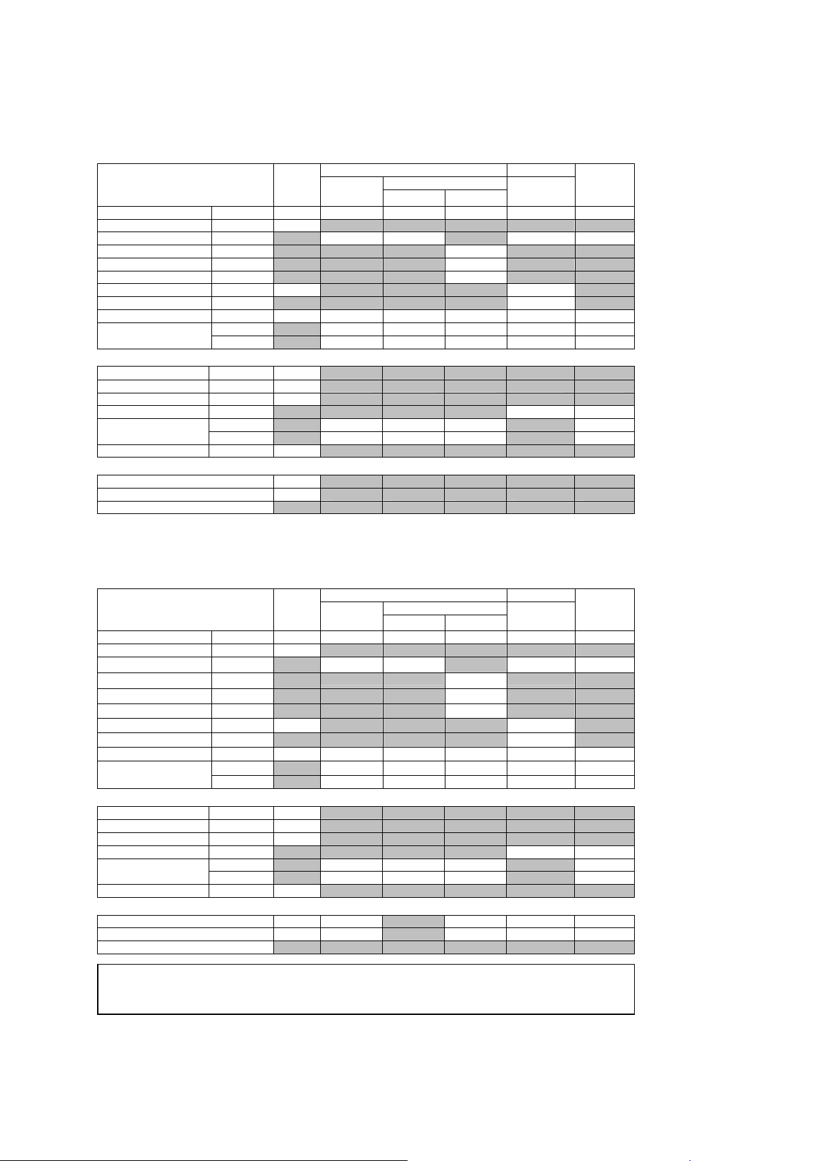
Track 3, FDA 510(k) Acoustic Output Reporting
Data presented in Track 3 format represents the average MI/TI values for
five transducers measured under worst-case acoustic output conditions. The
on-screen MI/TI values are based on measurements on one transducer
under worst case acoutstic output conditions - rounded up to the nearest
display increment. It is possible that the values displayed on screen may
exceed the MI/TI values presented in the Track 3 format.
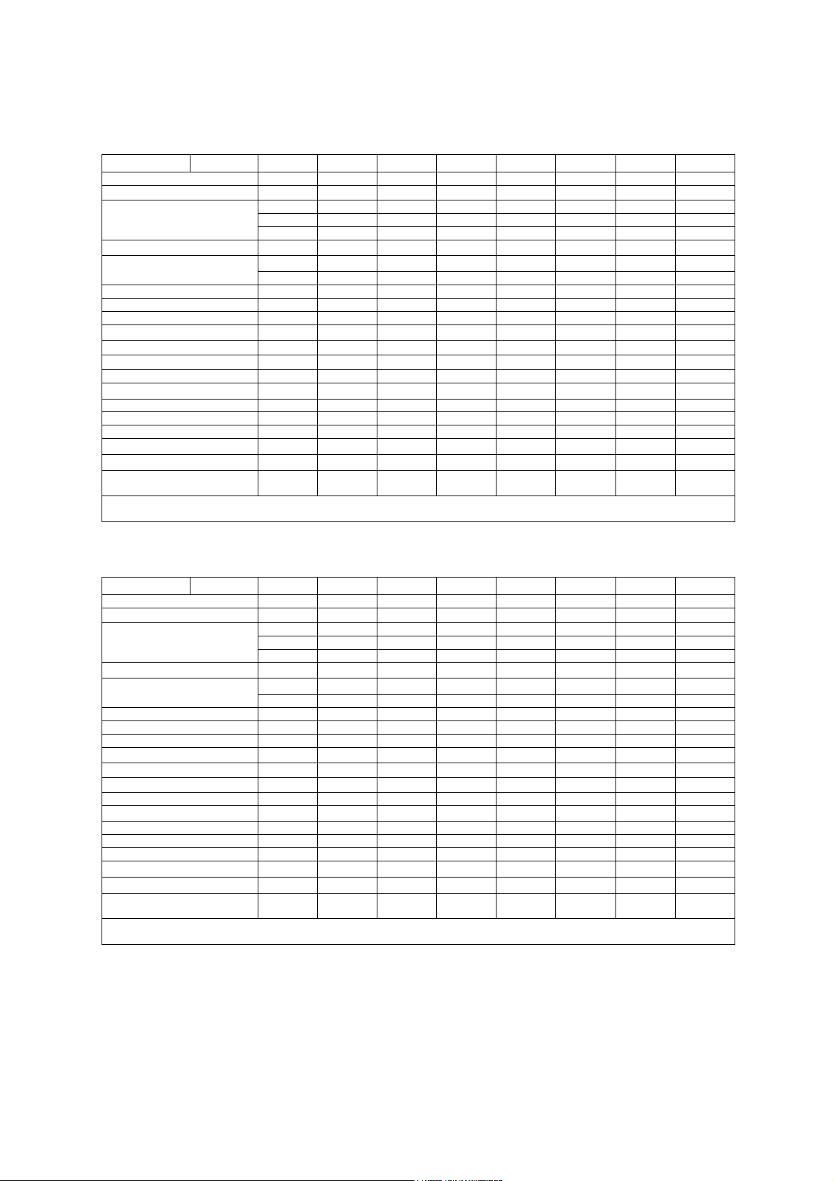
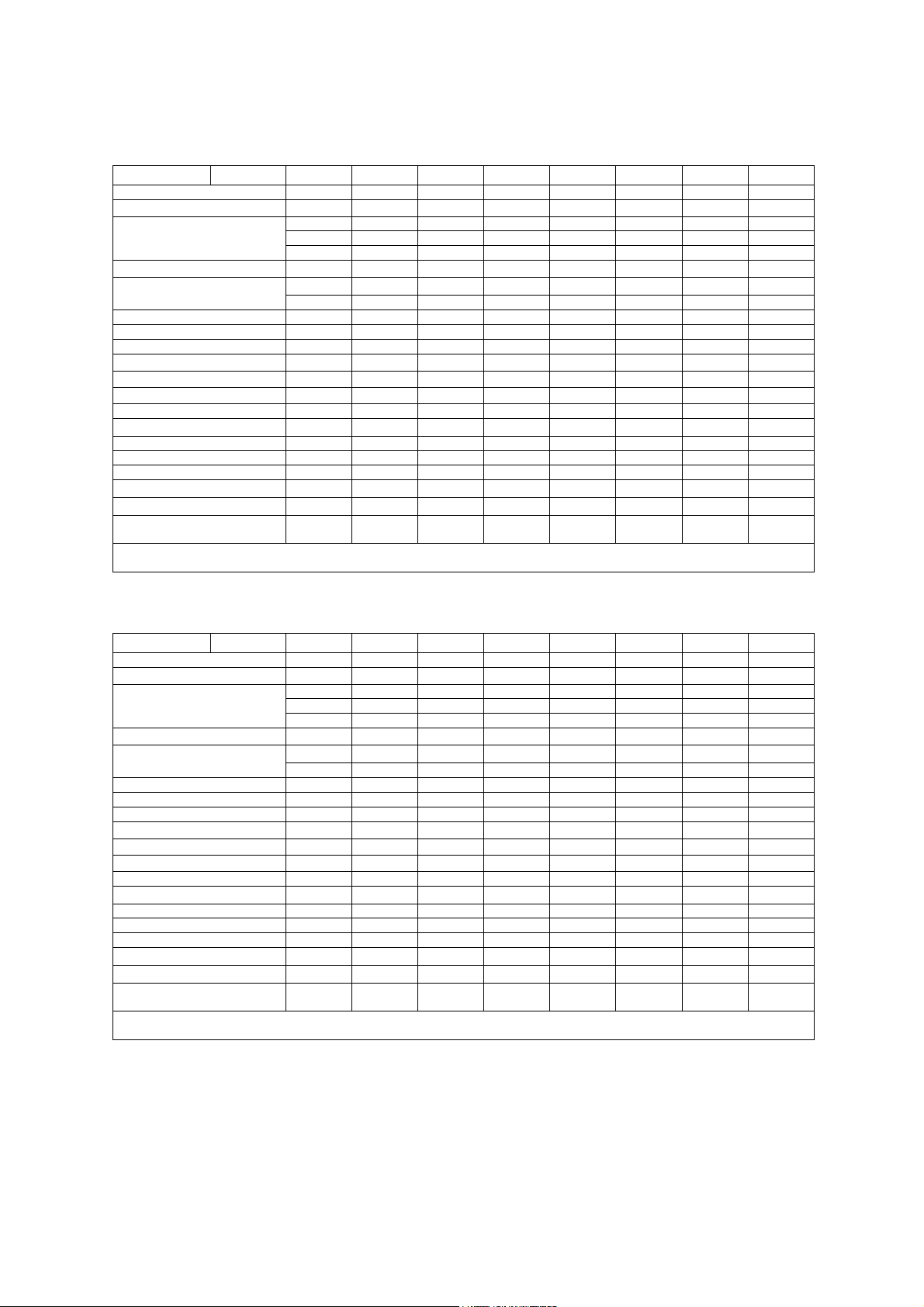
Summary Table for Acoustic Output
An "X" indicates that either the MI index or TI indices is greater than 1.0 for
each transducer/mode. A Track 3 format acoustic output table is supplied for
each transducer/mode combination marked with an "X".
Operating Mode Transducer Model
P4-2
P9-4
L10-5
7.5L70
VF13-5
VF13-5SP
5.0L45
C6-2
CH5-2
C6-3 3D/C6F3
5.0C50+
C8-5
EC9-4
BE9-4
EV9-4
CW2
B-mode (2D)
M-mode
Pulsed Doppler
Color Flow
or Power
CW Doppler
X X
X X
X X X X X X X XXXXXX X
X X XX X X X XXXXXXXX
X X
X X X X X X
X X X X X X
The following rules apply to the summary table:
X X
X X
X
X
CW5
X X
System Reference
IEC 61157 1-6
B-mode (2D) No other mode active.
Only MI (when larger than 1.0) is reported for this mode.
M-mode Includes simultaneous B-mode.
PW-Doppler In duplex modes, the largest displayed TIS (scanned or non-scanned)
is reported if it is larger than 1.0.
Color Flow
or Power
Other The output is reported as a separate mode if the largest formulation
Includes simultaneous color flow M-mode, B-mode, and Doppler.
In combined modes, the largest displayed TIS (scanned or
non-scanned) is reported if it is larger than 1.0.
of TIS, TIB, or TIC (if an intended use) is greater than the
corresponding value reported for all constituent mode.
TIC is reported if the transducer is intended for transcranial or
neonatal cephalic use.
SYSTEM REFERENCE 1 - 15
Page 26

1 Acoustic Output Reference
Definitions
Symbol Definition Units
MI Mechanical Index N/A
TIS Scan Soft Tissue Thermal Index in autoscanning mode N/A
TIS Non-scan Soft Tissue Thermal Index in non-autoscanning mode N/A
TIB Bone Thermal Index N/A
TIC Cranial Thermal Index N/A
A
Area of the active aperture cm2
aprt
P
r.3
Wo
W
)
.
3(Z1
I
) Derated spatial-peak, temporal-average intensity at axial distance Z1.
TA.3(Z1
Z1
Zbp
Zsp For MI: axial distance at which P
deq (Zsp) Equivalent beam diameter as a function of axial distance, and is equal to
fc Center frequency MHz
Dim. of A
aprt
PD Pulse duration
PRF Pulse repetition frequency Hz
Pr @ PII
d eq@ PII
Peak rarefactional pressure at the point where the free-field, spatial-peak
max
max
FL Focal Length, or azimuthal and elevational lengths, if different cm
I
@ MI
pa.3
max
Derated peak rarefactional pressure MPa
Ultrasonic power, except for TIS Scan, in which case it is the ultrasonic
mW
power passing through a one centimeter window.
Derated ultrasonic power at axial distance Z
mW
1
mW/cm
Axial distance corresponding to the location of the max
[W
), I
.
3(Z1
1.69 (A
(Z) x 1 cm2)], where Z > Zbp.
TA.3
1/2
)
.
aprt
is measured
r.3
For TIB: axial distance at which TIB is a maximum (i.e., Z
sp
= Z
B.3
)
cm2
cm
cm
cm
where ITA (Z) is the temporal-average intensity as a function of Z
Active aperture dimensions for the azimuth and elevational planes cm
μs
MPa
pulse intensity integral is a maximum
Equivalent beam diameter at the point where the free-field, spatial-peak
cm
pulse intensity integral is a maximum
Derated pulse-average intensity at the point of global maximum W/cm2
2
1 - 16 SYSTEM REFERENCE
Page 27
1 Acoustic Output Reference
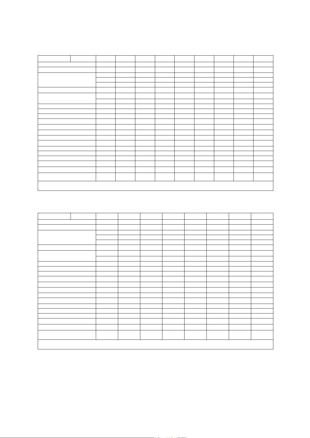
Acoustic Output Reporting Table – Track 3, FDA 510(k)
(Per transducer/mode that exceeds MI or TI value of 1.0)
Transducer model: P4-2 Operating mode: B-mode
Associated Acoustic Parameters
Maximum Value --- 1.5 (a) (a) (a) (a) (a)
min of [W.3(Z1), ITA.3(Z1)] (mW) #
deq (Zsp) (cm) #
Dim. of Aaprt X (cm) # # # # #
Other information
Pr @ PII max (MPa) 3.3
d eq@ PII max (cm) # #
Focal Length FLx (cm) # # # #
I pa.3 @ MI max (W/cm2) 570
Operator Control
MI TIS TIB TIC
Index Label Scan Non-scan Non-scan
Pr.3 (MPa) 2.4
Wo (mW) # # # #
Z1 (cm) #
Zbp (cm) #
Zsp (cm) 3.9 #
fc (MHz) 2.5 # # # # #
Y (cm) # # # # #
PD
PRF (Hz) 4500
FLy (cm) # # # #
TX-Level (dB) 0
Focus (mm) 49
PRF (Hz)
(μsec)
0.43
A
aprt
≤1
A
>1
aprt
Acoustic Output Reporting Table – Track 3, FDA 510(k)
(Per transducer/mode that exceeds MI or TI value of 1.0)
Transducer model: P4-2 Operating mode: M-mode
Associated Acoustic Parameters
Maximum Value --- 1.5 1.6 --- 0.26 1.4 2.2
min of [W
.
deq (Zsp)
Dim. of A
Other information
Pr @ PII max (MPa) 3.3
d eq@ PII max (cm) 0.24 1.0
Focal Length FLx (cm) 14 # 14 7.1
I pa.3 @ MI max (W/cm2) 570
Operator Control
a This Index is not relevant to this operating mode.
b This transducer is not intended for transcranial or neonatal cephalic uses.
c This formulation for TIS is less than that for an alternate formulation in this mode.
# No data is provided for this operation condition since the maximum index value is not reported for the reason listed.
MI TIS TIB TIC
Index Label Scan Non-scan Non-scan
Pr.3 (MPa) 2.4
W
o
), I
3(Z1
TA.3(Z1
Z1 (cm) 2.5
Zbp
Zsp
fc
aprt
Y (cm) 1.3 # 1.3 1.3 1.3
PD
PRF (Hz) 1000
FLy (cm) 5.5 # 5.5 5.5
TX-Level (dB) 0 0 0 0 0
Focus (mm) 49 140 140 49 71
PRF (Hz)
(mW) 350 # 26 350
)] (mW) 15
(cm)
(cm) 3.9
(cm)
(MHz) 2.5 2.6 # 2.6 2.1 2.4
X (cm)
(μsec)
2.5
3.6
0.25
1.7 # 1.7 1.4 1.7
0.43
A
aprt
≤1
A
>1
aprt
SYSTEM REFERENCE 1 - 17
Page 28
1 Acoustic Output Reference
Acoustic Output Reporting Table – Track 3, FDA 510(k)
(Per transducer/mode that exceeds MI or TI value of 1.0)
Transducer model: P4-2 Operating mode: Pulsed Doppler
Associated Acoustic Parameters
MI TIS TIB TIC
Index Label Scan Non-scan Non-scan
A
A
Maximum Value --- 1.1 --- --- 1.1 3.9 2.2
P
(MPa) 1.7
r.3
min of [W
Dim. of A
W
o
), I
.
3(Z1
TA.3(Z1
Z1 (cm) 2.7
Zbp
Zsp
deq (Zsp)
fc
aprt
Y (cm) # # 1.3 1.3 1.3
(mW) # # 160 160
)] (mW) 92
(cm)
(cm) 3.7
(cm)
(MHz) 2.1 # # 2.1 2.1 2.1
X (cm)
2.7
3.8
0.59
# # 2.0 2.0 2.0
aprt
≤1
Other information
PD
PRF (Hz) 1300
Pr @ PII max (MPa) 2.0
d eq@ PII max (cm) 0.59 0.59
Focal Length FLx (cm) # # 14 14
FLy (cm) # # 5.5 5.5
I pa.3 @ MI max (W/cm2) 200
(μsec)
1.8
Operator Control
TX-Level (dB) 0 0 0 0
Focus (mm) 27 140 140 140
PRF (Hz) 13800 13800 13800
aprt
>1
Acoustic Output Reporting Table – Track 3, FDA 510(k)
(Per transducer/mode that exceeds MI or TI value of 1.0)
Transducer model: P4-2 Operating mode: Color / Power
Associated Acoustic Parameters
Maximum Value --- 1.3 --- --- 1.3 4.5 2.6
min of [W
.
deq (Zsp)
Dim. of A
Other information
Pr @ PII max (MPa) 3.0
d eq@ PII max (cm) 0.55 0.55
Focal Length FLx (cm) # # 14 14
I pa.3 @ MI max (W/cm2) 390
Operator Control
a This Index is not relevant to this operating mode.
b This transducer is not intended for transcranial or neonatal cephalic uses.
c This formulation for TIS is less than that for an alternate formulation in this mode.
# No data is provided for this operation condition since the maximum index value is not reported for the reason listed.
MI TIS TIB TIC
Index Label Scan Non-scan Non-scan
Pr.3 (MPa) 1.9
W
o
), I
3(Z1
TA.3(Z1
Z1 (cm) 2.7
Zbp
Zsp
fc
aprt
Y (cm) # # 1.3 1.3 1.3
PD
PRF (Hz) 1300
FLy (cm) # # 5.5 5.5
TX-Level (dB) 0 0 0 0
Focus (mm) 71 140 140 140
PRF (Hz) 4000 4000 4000
(mW) # # 190 190
)] (mW) 110
(cm)
(cm) 5.6
(cm)
(MHz) 2.1 # # 2.1 2.1 2.1
X (cm)
(μsec)
2.7
3.8
0.55
# # 2.0 2.0 2.0
1.8
A
aprt
≤1
A
>1
aprt
1 - 18 SYSTEM REFERENCE
Page 29
1 Acoustic Output Reference
Acoustic Output Reporting Table – Track 3, FDA 510(k)
(Per transducer/mode that exceeds MI or TI value of 1.0)
Transducer model: P4-2 Operating mode: CW Doppler
Associated Acoustic Parameters
Maximum Value --- 0.08 --- 0.49 # 2.6 1.1
min of [W
.
deq (Zsp)
Dim. of A
Other information
Pr @ PII max (MPa) 0.16
d eq@ PII max (cm) 0.26 0.26
Focal Length FLx (cm) # 4.1 # 5.9
I pa.3 @ MI max (W/cm2) 0.54
Operator Control
MI TIS TIB TIC
Index Label Scan Non-scan Non-scan
P
(MPa) 0.12
r.3
W
o
), I
3(Z1
TA.3(Z1
Z1 (cm) #
Zbp
Zsp
fc
aprt
Y (cm) # 1.3 # 1.3 1.3
PD
PRF (Hz) -
FLy (cm) # 5.5 # 5.5
TX-Level (dB) 0 0 0 0
Focus (mm) 59 41 59 59
PRF (Hz)
(mW) # 41 55 55
)] (mW) #
(cm)
(cm) 3.7
(cm)
(MHz) 2.2 # 2.5 # 2.2 2.2
X (cm)
(μsec)
#
3.7
0.27
# 0.71 # 0.93 0.93
-
A
aprt
≤1
A
>1
aprt
Acoustic Output Reporting Table – Track 3, FDA 510(k)
(Per transducer/mode that exceeds MI or TI value of 1.0)
Transducer model: P9-4 Operating mode: B-mode
Associated Acoustic Parameters
Maximum Value --- 1.5 (a) (a) (a) (a) (a)
min of [W.3(Z1), ITA.3(Z1)] (mW) #
deq (Zsp) (cm) #
Dim. of Aaprt X (cm) # # # # #
Other information
Pr @ PII max (MPa) 3.4
d eq@ PII max (cm) # #
Focal Length FLx (cm) # # # #
I pa.3 @ MI max (W/cm2) 800
Operator Control
a This Index is not relevant to this operating mode.
b This transducer is not intended for transcranial or neonatal cephalic uses.
c This formulation for TIS is less than that for an alternate formulation in this mode.
# No data is provided for this operation condition since the maximum index value is not reported for the reason listed.
MI TIS TIB TIC
Index Label Scan Non-scan Non-scan
Pr.3 (MPa) 3.4
Wo (mW) # # # #
Z1 (cm) #
Zbp (cm) #
Zsp (cm) 0.60 #
fc (MHz) 5.4 # # # # #
Y (cm) # # # # #
PD
PRF (Hz) 2900
FLy (cm) # # # #
TX-Level (dB) 0
Focus (mm) 11
PRF (Hz)
(μsec)
0.12
A
aprt
≤1
A
>1
aprt
SYSTEM REFERENCE 1 - 19
Page 30

1 Acoustic Output Reference
Acoustic Output Reporting Table – Track 3, FDA 510(k)
(Per transducer/mode that exceeds MI or TI value of 1.0)
Transducer model: P9-4 Operating mode: M-mode
Associated Acoustic Parameters
Maximum Value --- 1.5 2.4 0.49 --- 0.63 1.6
min of [W
.
deq (Zsp)
Dim. of A
Other information
Pr @ PII max (MPa) 3.4
d eq@ PII max (cm) 0.28 1.1
Focal Length FLx (cm) 14 14 # 6.0
I pa.3 @ MI max (W/cm2) 800
Operator Control
MI TIS TIB TIC
Index Label Scan Non-scan Non-scan
Pr.3 (MPa) 3.4
W
o
), I
3(Z1
TA.3(Z1
Z1 (cm) #
Zbp
Zsp
fc
aprt
Y (cm) 0.80 0.80 # 0.80 0.80
PD
PRF (Hz) 1000
FLy (cm) 3.5 3.5 # 3.5
TX-Level (dB) 0 0 0 0 0
Focus (mm) 11 140 140 11 60
PRF (Hz)
(mW) 57 14 6.6 57
)] (mW) #
(cm)
(cm) 0.60
(cm)
(MHz) 5.4 5.4 5.4 # 5.6 5.1
X (cm)
(μsec)
#
0.56
1.3
0.77 0.77 # 0.36 0.77
0.12
A
aprt
≤1
A
>1
aprt
Acoustic Output Reporting Table – Track 3, FDA 510(k)
(Per transducer/mode that exceeds MI or TI value of 1.0)
Transducer model: P9-4 Operating mode: Pulsed Doppler
Associated Acoustic Parameters
MI TIS TIB TIC
Index Label Scan Non-scan Non-scan
A
A
Maximum Value --- 0.82 --- 1.5 --- 2.6 1.6
P
(MPa) 1.9
r.3
min of [W
Dim. of A
W
o
), I
.
3(Z1
TA.3(Z1
Z1 (cm) #
Zbp
Zsp
deq (Zsp)
fc
aprt
Y (cm) # 0.80 # 0.80 0.80
(mW) # 57 75 57
)] (mW) #
(cm)
(cm) 0.50
(cm)
(MHz) 5.3 # 5.3 # 3.7 5.3
X (cm)
#
4.1
0.25
# 0.77 # 0.77 0.77
aprt
≤1
Other information
PD
PRF (Hz) 1300
Pr @ PII max (MPa) 2.0
d eq@ PII max (cm) 0.25 0.29
Focal Length FLx (cm) # 10 # 6.0
FLy (cm) # 3.5 # 3.5
I pa.3 @ MI max (W/cm2) 180
(μsec)
1.4
Operator Control
TX-Level (dB) 0 0 0 0
Focus (mm) 9.0 100 60 60
a This Index is not relevant to this operating mode.
b This transducer is not intended for transcranial or neonatal cephalic uses.
c This formulation for TIS is less than that for an alternate formulation in this mode.
# No data is provided for this operation condition since the maximum index value is not reported for the reason listed.
PRF (Hz) 10400 12500 10400
aprt
>1
1 - 20 SYSTEM REFERENCE
Page 31

1 Acoustic Output Reference
Acoustic Output Reporting Table – Track 3, FDA 510(k)
(Per transducer/mode that exceeds MI or TI value of 1.0)
Transducer model: P9-4 Operating mode: Color / Power
Associated Acoustic Parameters
Maximum Value --- 1.1 --- 2.3 --- 2.3 1.8
min of [W
.
deq (Zsp)
Dim. of A
Other information
Pr @ PII max (MPa) 2.5
d eq@ PII max (cm) 0.22 0.24
Focal Length FLx (cm) # 10 # 6.0
I pa.3 @ MI max (W/cm2) 370
Operator Control
MI TIS TIB TIC
Index Label Scan Non-scan Non-scan
Pr.3 (MPa) 2.5
W
o
), I
3(Z1
TA.3(Z1
Z1 (cm) #
Zbp
Zsp
fc
aprt
Y (cm) # 0.80 # 0.80 0.80
PD
PRF (Hz) 1300
FLy (cm) # 3.5 # 3.5
TX-Level (dB) 0 0 0 0
Focus (mm) 11 100 29 60
PRF (Hz) 1300 10400 1700
(mW) # 55 40 63
)] (mW) #
(cm)
(cm) 0.60
(cm)
(MHz) 5.3 # 5.2 # 3.7 3.7
X (cm)
(μsec)
#
2.8
0.22
# 0.77 # 0.58 0.77
0.72
A
aprt
≤1
A
>1
aprt
Acoustic Output Reporting Table – Track 3, FDA 510(k)
(Per transducer/mode that exceeds MI or TI value of 1.0)
Transducer model: P9-4 Operating mode: CW Doppler
Associated Acoustic Parameters
Maximum Value --- 0.06 --- 0.94 # 1.9 1.6
min of [W
.
deq (Zsp)
Dim. of A
Other information
Pr @ PII max (MPa) 0.15
d eq@ PII max (cm) 0.21 0.18
Focal Length FLx (cm) # 2.9 # 2.9
I pa.3 @ MI max (W/cm2) 0.53
Operator Control
a This Index is not relevant to this operating mode.
b This transducer is not intended for transcranial or neonatal cephalic uses.
c This formulation for TIS is less than that for an alternate formulation in this mode.
# No data is provided for this operation condition since the maximum index value is not reported for the reason listed.
MI TIS TIB TIC
Index Label Scan Non-scan Non-scan
P
(MPa) 0.12
r.3
W
o
), I
3(Z1
TA.3(Z1
Z1 (cm) #
Zbp
Zsp
fc
aprt
Y (cm) # 0.80 # 0.80 0.80
PD
PRF (Hz) -
FLy (cm) # 3.5 # 3.5
TX-Level (dB) 0 0 0 0
Focus (mm) 35 29 35 29
PRF (Hz)
(mW) # 39 35 39
)] (mW) #
(cm)
(cm) 2.6
(cm)
(MHz) 3.8 # 5.1 # 3.8 5.1
X (cm)
(μsec)
#
2.6
0.21
# 0.36 # 0.36 0.36
-
A
aprt
≤1
A
>1
aprt
SYSTEM REFERENCE 1 - 21
Page 32

1 Acoustic Output Reference
Acoustic Output Reporting Table – Track 3, FDA 510(k)
(Per transducer/mode that exceeds MI or TI value of 1.0)
Transducer model: L10-5 Operating mode: Pulsed Doppler
Associated Acoustic Parameters
MI TIS TIB TIC
Index Label Scan Non-scan Non-scan
A
A
Maximum Value --- 0.84 --- 0.74 --- 1.1 0.69
P
(MPa) 1.9
r.3
min of [W
Dim. of A
W
o
), I
.
3(Z1
TA.3(Z1
Z1 (cm) #
Zbp
Zsp
deq (Zsp)
fc
aprt
Y (cm) # 0.50 # 0.50 0.50
(mW) # 23 17 23
)] (mW) #
(cm)
(cm) 1.9
(cm)
(MHz) 5.2 # 6.8 # 5.2 6.8
X (cm)
#
2.1
0.17
# 1.1 # 0.92 1.1
aprt
≤1
Other information
PD
PRF (Hz) 1300
Pr @ PII max (MPa) 2.7
d eq@ PII max (cm) 0.17 0.25
Focal Length FLx (cm) # 5.1 # 5.1
FLy (cm) # 2.0 # 2.0
I pa.3 @ MI max (W/cm2) 430
(μsec)
0.73
Operator Control
TX-Level (dB) 0 0 0 0
Focus (mm) 26 51 43 51
PRF (Hz) 15200 3300 15200
aprt
>1
Acoustic Output Reporting Table – Track 3, FDA 510(k)
(Per transducer/mode that exceeds MI or TI value of 1.0)
Transducer model: L10-5 Operating mode: Color / Power
Associated Acoustic Parameters
Maximum Value --- 1.1 --- 0.79 --- 1.2 0.74
min of [W
.
deq (Zsp)
Dim. of A
Other information
Pr @ PII max (MPa) 3.3
d eq@ PII max (cm) 0.17 0.25
Focal Length FLx (cm) # 5.1 # 5.1
I pa.3 @ MI max (W/cm2) 750
Operator Control
a This Index is not relevant to this operating mode.
b This transducer is not intended for transcranial or neonatal cephalic uses.
c This formulation for TIS is less than that for an alternate formulation in this mode.
# No data is provided for this operation condition since the maximum index value is not reported for the reason listed.
MI TIS TIB TIC
Index Label Scan Non-scan Non-scan
Pr.3 (MPa) 2.5
W
o
), I
3(Z1
TA.3(Z1
Z1 (cm) #
Zbp
Zsp
fc
aprt
Y (cm) # 0.50 # 0.50 0.50
PD
PRF (Hz) 1300
FLy (cm) # 2.0 # 2.0
TX-Level (dB) 0 0 0 0
Focus (mm) 26 51 43 51
PRF (Hz) 12500 10400 12500
(mW) # 24 18 24
)] (mW) #
(cm)
(cm) 1.7
(cm)
(MHz) 4.7 # 6.8 # 5.3 6.8
X (cm)
(μsec)
#
2.1
0.17
# 1.1 # 0.92 1.1
0.38
A
aprt
≤1
A
>1
aprt
1 - 22 SYSTEM REFERENCE
Page 33

1 Acoustic Output Reference
Acoustic Output Reporting Table – Track 3, FDA 510(k)
(Per transducer/mode that exceeds MI or TI value of 1.0)
Transducer model: 7.5L70 Operating mode: B-mode
Associated Acoustic Parameters
Maximum Value --- 1.1 (a) (a) (a) (a) (a)
min of [W
.
deq (Zsp)
Dim. of A
Other information
Pr @ PII max (MPa) 3.5
d eq@ PII max (cm) # #
Focal Length FLx (cm) # # # #
I pa.3 @ MI max (W/cm2) 500
Operator Control
MI TIS TIB TIC
Index Label Scan Non-scan Non-scan
P
(MPa) 2.7
r.3
W
o
), I
3(Z1
TA.3(Z1
Z1 (cm) #
Zbp
Zsp
fc
aprt
Y (cm) # # # # #
PD
PRF (Hz) 4500
FLy (cm) # # # #
TX-Level (dB) 0
Focus (mm) 20
PRF (Hz)
(mW) # # # #
)] (mW) #
(cm)
(cm) 1.3
(cm)
(MHz) 6.4 # # # # #
X (cm)
(μsec)
#
#
#
# # # # #
0.15
A
aprt
≤1
A
>1
aprt
Acoustic Output Reporting Table – Track 3, FDA 510(k)
(Per transducer/mode that exceeds MI or TI value of 1.0)
Transducer model: 7.5L70 Operating mode: M-mode
Associated Acoustic Parameters
Maximum Value --- 1.1 0.83 0.23 --- 0.34 1.0
min of [W
.
deq (Zsp)
Dim. of A
Other information
Pr @ PII max (MPa) 3.5
d eq@ PII max (cm) 0.39 1.3
Focal Length FLx (cm) 7.0 7.0 # 9.8
I pa.3 @ MI max (W/cm2) 500
Operator Control
a This Index is not relevant to this operating mode.
b This transducer is not intended for transcranial or neonatal cephalic uses.
c This formulation for TIS is less than that for an alternate formulation in this mode.
# No data is provided for this operation condition since the maximum index value is not reported for the reason listed.
MI TIS TIB TIC
Index Label Scan Non-scan Non-scan
Pr.3 (MPa) 2.7
W
o
), I
3(Z1
TA.3(Z1
Z1 (cm) #
Zbp
Zsp
fc
aprt
Y (cm) 0.50 0.50 # 0.50 0.50
PD
PRF (Hz) 1000
FLy (cm) 1.9 1.9 # 1.9
TX-Level (dB) 0 0 0 0 0
Focus (mm) 20 70 70 98 98
PRF (Hz)
(mW) 84 8.1 11 110
)] (mW) #
(cm)
(cm) 1.3
(cm)
(MHz) 6.4 6.0 6.0 # 6.1 6.1
X (cm)
(μsec)
#
1.3
0.41
1.7 1.7 # 2.3 2.3
0.15
A
aprt
≤1
A
>1
aprt
SYSTEM REFERENCE 1 - 23
Page 34

1 Acoustic Output Reference
Acoustic Output Reporting Table – Track 3, FDA 510(k)
(Per transducer/mode that exceeds MI or TI value of 1.0)
Transducer model: 7.5L70 Operating mode: Pulsed Doppler
Associated Acoustic Parameters
MI TIS TIB TIC
Index Label Scan Non-scan Non-scan
A
A
Maximum Value --- 1.0 --- 1.0 --- 1.4 0.95
P
(MPa) 2.4
r.3
min of [W
Dim. of A
W
o
), I
.
3(Z1
TA.3(Z1
Z1 (cm) #
Zbp
Zsp
deq (Zsp)
fc
aprt
Y (cm) # 0.50 # 0.50 0.50
(mW) # 31 40 40
)] (mW) #
(cm)
(cm) 1.2
(cm)
(MHz) 5.4 # 6.9 # 5.4 5.4
X (cm)
#
1.7
0.36
# 1.7 # 1.73 1.7
aprt
≤1
Other information
PD
PRF (Hz) 1300
Pr @ PII max (MPa) 2.9
d eq@ PII max (cm) 0.36 0.36
Focal Length FLx (cm) # 7.0 # 7.0
FLy (cm) # 1.9 # 1.9
I pa.3 @ MI max (W/cm2) 490
(μsec)
0.71
Operator Control
TX-Level (dB) 0 0 0 0
Focus (mm) 17 70 70 70
PRF (Hz) 15200 10400 10400
aprt
>1
Acoustic Output Reporting Table – Track 3, FDA 510(k)
(Per transducer/mode that exceeds MI or TI value of 1.0)
Transducer model: 7.5L70 Operating mode: Color / Power
Associated Acoustic Parameters
Maximum Value --- 1.1 --- 1.1 --- 1.3 0.94
min of [W
.
deq (Zsp)
Dim. of A
Other information
Pr @ PII max (MPa) 3.0
d eq@ PII max (cm) 0.31 0.31
Focal Length FLx (cm) # 7.0 # 7.0
I pa.3 @ MI max (W/cm2) 530
Operator Control
a This Index is not relevant to this operating mode.
b This transducer is not intended for transcranial or neonatal cephalic uses.
c This formulation for TIS is less than that for an alternate formulation in this mode.
# No data is provided for this operation condition since the maximum index value is not reported for the reason listed.
MI TIS TIB TIC
Index Label Scan Non-scan Non-scan
Pr.3 (MPa) 2.5
W
o
), I
3(Z1
TA.3(Z1
Z1 (cm) #
Zbp
Zsp
fc
aprt
Y (cm) # 0.50 # 0.50 0.50
PD
PRF (Hz) 1300
FLy (cm) # 1.9 # 1.9
TX-Level (dB) 0 0 0 0
Focus (mm) 17 70 70 70
PRF (Hz) 4000 3300 3300
(mW) # 33 39 39
)] (mW) #
(cm)
(cm) 1.2
(cm)
(MHz) 5.4 # 6.8 # 5.3 5.3
X (cm)
(μsec)
#
1.7
0.31
# 1.7 # 1.7 1.7
0.71
A
aprt
≤1
A
>1
aprt
1 - 24 SYSTEM REFERENCE
Page 35

1 Acoustic Output Reference
Acoustic Output Reporting Table – Track 3, FDA 510(k)
(Per transducer/mode that exceeds MI or TI value of 1.0)
Transducer model: VF13-5 Operating mode: B-mode
Associated Acoustic Parameters
Maximum Value --- 1.2 (a) (a) (a) (a) (a)
min of [W
.
deq (Zsp)
Dim. of A
Other information
Pr @ PII max (MPa) 3.3
d eq@ PII max (cm) # #
Focal Length FLx (cm) # # # #
I pa.3 @ MI max (W/cm2) 830
Operator Control
MI TIS TIB TIC
Index Label Scan Non-scan Non-scan
P
(MPa) 3.4
r.3
W
o
), I
3(Z1
TA.3(Z1
Z1 (cm) #
Zbp
Zsp
fc
aprt
Y (cm) # # # # #
PD
PRF (Hz) 4500
FLy (cm) # # # #
TX-Level (dB) 0
Focus (mm) 12
PRF (Hz)
(mW) # # # #
)] (mW) #
(cm)
(cm) 0.50
(cm)
(MHz) 7.7 # # # # #
X (cm)
(μsec)
#
#
#
# # # # #
0.12
A
aprt
≤1
A
>1
aprt
Acoustic Output Reporting Table – Track 3, FDA 510(k)
(Per transducer/mode that exceeds MI or TI value of 1.0)
Transducer model: VF13-5 Operating mode: M-mode
Associated Acoustic Parameters
Maximum Value --- 1.2 0.91 0.16 --- 0.28 0.81
min of [W
.
deq (Zsp)
Dim. of A
Other information
Pr @ PII max (MPa) 3.3
d eq@ PII max (cm) 0.26 1.5
Focal Length FLx (cm) 5.1 5.1 # 5.1
I pa.3 @ MI max (W/cm2) 830
Operator Control
a This Index is not relevant to this operating mode.
b This transducer is not intended for transcranial or neonatal cephalic uses.
c This formulation for TIS is less than that for an alternate formulation in this mode.
# No data is provided for this operation condition since the maximum index value is not reported for the reason listed.
MI TIS TIB TIC
Index Label Scan Non-scan Non-scan
Pr.3 (MPa) 3.4
W
o
), I
3(Z1
TA.3(Z1
Z1 (cm) #
Zbp
Zsp
fc
aprt
Y (cm) 0.25 0.25 # 0.25 0.25
PD
PRF (Hz) 1000
FLy (cm) 0.60 0.60 # 0.60
TX-Level (dB) 0 0 0 0 0
Focus (mm) 12 51 51 71 51
PRF (Hz)
(mW) 47 4.5 4.2 48
)] (mW) #
(cm)
(cm) 0.50
(cm)
(MHz) 7.7 7.4 7.4 # 7.2 6.1
X (cm)
(μsec)
#
0.50
0.26
1.3 1.3 # 1.3 1.3
0.12
A
aprt
≤1
A
>1
aprt
SYSTEM REFERENCE 1 - 25
Page 36

1 Acoustic Output Reference
Acoustic Output Reporting Table – Track 3, FDA 510(k)
(Per transducer/mode that exceeds MI or TI value of 1.0)
Transducer model: VF13-5 Operating mode: Pulsed Doppler
Associated Acoustic Parameters
MI TIS TIB TIC
Index Label Scan Non-scan Non-scan
A
A
Maximum Value --- 1.2 --- 1.1 --- 2.5 1.2
P
(MPa) 3.2
r.3
min of [W
Dim. of A
W
o
), I
.
3(Z1
TA.3(Z1
Z1 (cm) #
Zbp
Zsp
deq (Zsp)
fc
aprt
Y (cm) # 0.25 # 0.25 0.25
(mW) # 31 31 31
)] (mW) #
(cm)
(cm) 0.30
(cm)
(MHz) 7.0 # 6.9 # 6.9 6.9
X (cm)
#
0.50
0.24
# 1.3 # 1.3 1.3
aprt
≤1
Other information
PD
PRF (Hz) 1300
Pr @ PII max (MPa) 3.3
d eq@ PII max (cm) 0.24 0.24
Focal Length FLx (cm) # 5.1 # 5.1
FLy (cm) # 0.60 # 0.60
I pa.3 @ MI max (W/cm2) 640
(μsec)
0.54
Operator Control
TX-Level (dB) 0 0 0 0
Focus (mm) 5 51 51 51
PRF (Hz) 1900 1900 1900
aprt
>1
Acoustic Output Reporting Table – Track 3, FDA 510(k)
(Per transducer/mode that exceeds MI or TI value of 1.0)
Transducer model: VF13-5 Operating mode: Color / Power
Associated Acoustic Parameters
Maximum Value --- 1.2 --- 1.0 --- 2.4 1.2
min of [W
.
deq (Zsp)
Dim. of A
Other information
Pr @ PII max (MPa) 3.3
d eq@ PII max (cm) 0.24 0.24
Focal Length FLx (cm) # 5.1 # 5.1
I pa.3 @ MI max (W/cm2) 640
Operator Control
a This Index is not relevant to this operating mode.
b This transducer is not intended for transcranial or neonatal cephalic uses.
c This formulation for TIS is less than that for an alternate formulation in this mode.
# No data is provided for this operation condition since the maximum index value is not reported for the reason listed.
MI TIS TIB TIC
Index Label Scan Non-scan Non-scan
Pr.3 (MPa) 3.2
W
o
), I
3(Z1
TA.3(Z1
Z1 (cm) #
Zbp
Zsp
fc
aprt
Y (cm) # 0.25 # 0.25 0.25
PD
PRF (Hz) 1300
FLy (cm) # 0.60 # 0.60
TX-Level (dB) 0 0 0 0
Focus (mm) 5 51 51 51
PRF (Hz) 1900 1900 1900
(mW) # 30 30 30
)] (mW) #
(cm)
(cm) 0.30
(cm)
(MHz) 7.0 # 6.9 # 6.9 6.9
X (cm)
(μsec)
#
0.50
0.24
# 1.3 # 1.3 1.3
0.54
A
aprt
≤1
A
>1
aprt
1 - 26 SYSTEM REFERENCE
Page 37

1 Acoustic Output Reference
Acoustic Output Reporting Table – Track 3, FDA 510(k)
(Per transducer/mode that exceeds MI or TI value of 1.0)
Transducer model: VF13-5SP Operating mode: B-mode
Associated Acoustic Parameters
Maximum Value --- 1.2 (a) (a) (a) (a) (a)
min of [W
.
deq (Zsp)
Dim. of A
Other information
Pr @ PII max (MPa) 3.3
d eq@ PII max (cm) # #
Focal Length FLx (cm) # # # #
I pa.3 @ MI max (W/cm2) 830
Operator Control
MI TIS TIB TIC
Index Label Scan Non-scan Non-scan
P
(MPa) 3.4
r.3
W
o
), I
3(Z1
TA.3(Z1
Z1 (cm) #
Zbp
Zsp
fc
aprt
Y (cm) # # # # #
PD
PRF (Hz) 4500
FLy (cm) # # # #
TX-Level (dB) 0
Focus (mm) 12
PRF (Hz)
(mW) # # # #
)] (mW) #
(cm)
(cm) 0.50
(cm)
(MHz) 7.7 # # # # #
X (cm)
(μsec)
#
#
#
# # # # #
0.12
A
aprt
≤1
A
>1
aprt
Acoustic Output Reporting Table – Track 3, FDA 510(k)
(Per transducer/mode that exceeds MI or TI value of 1.0)
Transducer model: VF13-5SP Operating mode: M-mode
Associated Acoustic Parameters
Maximum Value --- 1.2 1.1 0.19 --- 0.38 0.99
min of [W
.
deq (Zsp)
Dim. of A
Other information
Pr @ PII max (MPa) 3.3
d eq@ PII max (cm) 0.26 1.0
Focal Length FLx (cm) 5.1 5.1 # 5.1
I pa.3 @ MI max (W/cm2) 830
Operator Control
a This Index is not relevant to this operating mode.
b This transducer is not intended for transcranial or neonatal cephalic uses.
c This formulation for TIS is less than that for an alternate formulation in this mode.
# No data is provided for this operation condition since the maximum index value is not reported for the reason listed.
MI TIS TIB TIC
Index Label Scan Non-scan Non-scan
Pr.3 (MPa) 3.4
W
o
), I
3(Z1
TA.3(Z1
Z1 (cm) #
Zbp
Zsp
fc
aprt
Y (cm) 0.25 0.25 # 0.25 0.25
PD
PRF (Hz) 1000
FLy (cm) 0.60 0.60 # 0.60
TX-Level (dB) 0 0 0 0 0
Focus (mm) 12 51 51 71 51
PRF (Hz)
(mW) 58 5.6 5.6 58
)] (mW) #
(cm)
(cm) 0.50
(cm)
(MHz) 7.7 7.2 7.2 # 7.2 7.2
X (cm)
(μsec)
#
0.50
0.26
1.3 1.3 # 1.3 1.3
0.12
A
aprt
≤1
A
>1
aprt
SYSTEM REFERENCE 1 - 27
Page 38

1 Acoustic Output Reference
Acoustic Output Reporting Table – Track 3, FDA 510(k)
(Per transducer/mode that exceeds MI or TI value of 1.0)
Transducer model: VF13-5SP Operating mode: Pulsed Doppler
Associated Acoustic Parameters
MI TIS TIB TIC
Index Label Scan Non-scan Non-scan
A
A
Maximum Value --- 1.2 --- 0.88 --- 2.1 1.0
P
(MPa) 3.2
r.3
min of [W
Dim. of A
W
o
), I
.
3(Z1
TA.3(Z1
Z1 (cm) #
Zbp
Zsp
deq (Zsp)
fc
aprt
Y (cm) # 0.25 # 0.25 0.25
(mW) # 26 26 26
)] (mW) #
(cm)
(cm) 0.30
(cm)
(MHz) 7.0 # 7.0 # 7.0 7.0
X (cm)
#
0.50
0.22
# 1.3 # 1.3 1.3
aprt
≤1
Other information
PD
PRF (Hz) 1300
Pr @ PII max (MPa) 3.3
d eq@ PII max (cm) 0.22 0.22
Focal Length FLx (cm) # 5.1 # 5.1
FLy (cm) # 0.60 # 0.60
I pa.3 @ MI max (W/cm2) 640
(μsec)
0.54
Operator Control
TX-Level (dB) 0 0 0 0
Focus (mm) 5 51 51 51
PRF (Hz) 8600 8600 8600
aprt
>1
Acoustic Output Reporting Table – Track 3, FDA 510(k)
(Per transducer/mode that exceeds MI or TI value of 1.0)
Transducer model: VF13-5SP Operating mode: Color / Power
Associated Acoustic Parameters
Maximum Value --- 1.2 --- 1.0 --- 2.3 1.1
min of [W
.
deq (Zsp)
Dim. of A
Other information
Pr @ PII max (MPa) 3.3
d eq@ PII max (cm) 0.24 0.24
Focal Length FLx (cm) # 5.1 # 5.1
I pa.3 @ MI max (W/cm2) 640
Operator Control
a This Index is not relevant to this operating mode.
b This transducer is not intended for transcranial or neonatal cephalic uses.
c This formulation for TIS is less than that for an alternate formulation in this mode.
# No data is provided for this operation condition since the maximum index value is not reported for the reason listed.
MI TIS TIB TIC
Index Label Scan Non-scan Non-scan
Pr.3 (MPa) 3.2
W
o
), I
3(Z1
TA.3(Z1
Z1 (cm) #
Zbp
Zsp
fc
aprt
Y (cm) # 0.25 # 0.25 0.25
PD
PRF (Hz) 1300
FLy (cm) # 0.60 # 0.60
TX-Level (dB) 0 0 0 0
Focus (mm) 5 51 51 51
PRF (Hz) 1900 1900 1900
(mW) # 28 28 28
)] (mW) #
(cm)
(cm) 0.30
(cm)
(MHz) 7.0 # 6.9 # 6.9 6.9
X (cm)
(μsec)
#
0.50
0.24
# 1.3 # 1.3 1.3
0.54
A
aprt
≤1
A
>1
aprt
1 - 28 SYSTEM REFERENCE
Page 39

1 Acoustic Output Reference
Acoustic Output Reporting Table – Track 3, FDA 510(k)
(Per transducer/mode that exceeds MI or TI value of 1.0)
Transducer model: 5.0L45 Operating mode: B-mode
Associated Acoustic Parameters
Maximum Value --- 1.2 (a) (a) (a) (a) (a)
min of [W
.
deq (Zsp)
Dim. of A
Other information
Pr @ PII max (MPa) 2.9
d eq@ PII max (cm) # #
Focal Length FLx (cm) # # # #
I pa.3 @ MI max (W/cm2) 510
Operator Control
MI TIS TIB TIC
Index Label Scan Non-scan Non-scan
P
(MPa) 2.3
r.3
W
o
), I
3(Z1
TA.3(Z1
Z1 (cm) #
Zbp
Zsp
fc
aprt
Y (cm) # # # # #
PD
PRF (Hz) 4500
FLy (cm) # # # #
TX-Level (dB) 0
Focus (mm) 35
PRF (Hz)
(mW) # # # #
)] (mW) #
(cm)
(cm) 2.3
(cm)
(MHz) 3.9 # # # # #
X (cm)
(μsec)
#
#
#
# # # # #
0.23
A
aprt
≤1
A
>1
aprt
Acoustic Output Reporting Table – Track 3, FDA 510(k)
(Per transducer/mode that exceeds MI or TI value of 1.0)
Transducer model: 5.0L45 Operating mode: M-mode
Associated Acoustic Parameters
Maximum Value --- 1.2 1.1 0.16 --- 0.30 0.87
min of [W
.
deq (Zsp)
Dim. of A
Other information
Pr @ PII max (MPa) 2.9
d eq@ PII max (cm) 0.14 1.3
Focal Length FLx (cm) 16 6.0 # 10
I pa.3 @ MI max (W/cm2) 510
Operator Control
a This Index is not relevant to this operating mode.
b This transducer is not intended for transcranial or neonatal cephalic uses.
c This formulation for TIS is less than that for an alternate formulation in this mode.
# No data is provided for this operation condition since the maximum index value is not reported for the reason listed.
MI TIS TIB TIC
Index Label Scan Non-scan Non-scan
Pr.3 (MPa) 2.3
W
o
), I
3(Z1
TA.3(Z1
Z1 (cm) #
Zbp
Zsp
fc
aprt
Y (cm) 0.70 0.70 # 0.70 0.70
PD
PRF (Hz) 1000
FLy (cm) 2.5 2.5 # 2.5
TX-Level (dB) 0 0 0 0 0
Focus (mm) 35 163 60 35 100
PRF (Hz)
(mW) 110 6.1 3.5 110
)] (mW) #
(cm)
(cm) 2.3
(cm)
(MHz) 3.9 5.1 5.6 # 3.9 5.0
X (cm)
(μsec)
#
2.3
0.14
2.0 1.3 # 0.81 2.0
0.23
A
aprt
≤1
A
>1
aprt
SYSTEM REFERENCE 1 - 29
Page 40

1 Acoustic Output Reference
Acoustic Output Reporting Table – Track 3, FDA 510(k)
(Per transducer/mode that exceeds MI or TI value of 1.0)
Transducer model: 5.0L45 Operating mode: Pulsed Doppler
Associated Acoustic Parameters
MI TIS TIB TIC
Index Label Scan Non-scan Non-scan
A
A
Maximum Value --- 1.1 --- 0.80 --- 1.9 1.3
P
(MPa) 2.0
r.3
min of [W
Dim. of A
W
o
), I
.
3(Z1
TA.3(Z1
Z1 (cm) #
Zbp
Zsp
deq (Zsp)
fc
aprt
Y (cm) # 0.70 # 0.70 0.70
(mW) # 46 52 69
)] (mW) #
(cm)
(cm) 2.2
(cm)
(MHz) 3.6 # 3.6 # 3.6 3.6
X (cm)
#
2.1
0.35
# 1.3 # 1.5 2.0
aprt
≤1
Other information
PD
PRF (Hz) 1300
Pr @ PII max (MPa) 2.6
d eq@ PII max (cm) 0.35 0.45
Focal Length FLx (cm) # 6.0 # 10
FLy (cm) # 2.5 # 2.5
I pa.3 @ MI max (W/cm2) 320
(μsec)
1.1
Operator Control
TX-Level (dB) 0 0 0 0
Focus (mm) 35 60 71 100
PRF (Hz) 12500 7100 7100
aprt
>1
Acoustic Output Reporting Table – Track 3, FDA 510(k)
(Per transducer/mode that exceeds MI or TI value of 1.0)
Transducer model: 5.0L45 Operating mode: Color / Power
Associated Acoustic Parameters
Maximum Value --- 1.1 --- 0.72 --- 1.6 1.2
min of [W
.
deq (Zsp)
Dim. of A
Other information
Pr @ PII max (MPa) 2.7
d eq@ PII max (cm) 0.17 0.97
Focal Length FLx (cm) # 6.0 # 10
I pa.3 @ MI max (W/cm2) 320
Operator Control
a This Index is not relevant to this operating mode.
b This transducer is not intended for transcranial or neonatal cephalic uses.
c This formulation for TIS is less than that for an alternate formulation in this mode.
# No data is provided for this operation condition since the maximum index value is not reported for the reason listed.
MI TIS TIB TIC
Index Label Scan Non-scan Non-scan
Pr.3 (MPa) 2.1
W
o
), I
3(Z1
TA.3(Z1
Z1 (cm) #
Zbp
Zsp
fc
aprt
Y (cm) # 0.70 # 0.70 0.70
PD
PRF (Hz) 1300
FLy (cm) # 2.5 # 2.5
TX-Level (dB) 0 0 0 0
Focus (mm) 35 60 35 100
PRF (Hz) 3000 8600 3000
(mW) # 150 21 330
)] (mW) #
(cm)
(cm) 2.2
(cm)
(MHz) 3.6 # 3.6 # 3.6 3.6
X (cm)
(μsec)
#
2.2
0.17
# 1.3 # 0.81 2.0
1.1
A
aprt
≤1
A
>1
aprt
1 - 30 SYSTEM REFERENCE
Page 41

1 Acoustic Output Reference
Acoustic Output Reporting Table – Track 3, FDA 510(k)
(Per transducer/mode that exceeds MI or TI value of 1.0)
Transducer model: C6-2 Operating mode: B-mode
Associated Acoustic Parameters
Maximum Value --- 0.95 (a) (a) (a) (a) (a)
min of [W
.
deq (Zsp)
Dim. of A
Other information
Pr @ PII max (MPa) 2.4
d eq@ PII max (cm) # #
Focal Length FLx (cm) # # # #
I pa.3 @ MI max (W/cm2) 310
Operator Control
MI TIS TIB TIC
Index Label Scan Non-scan Non-scan
P
(MPa) 1.7
r.3
W
o
), I
3(Z1
TA.3(Z1
Z1 (cm) #
Zbp
Zsp
fc
aprt
Y (cm) # # # # #
PD
PRF (Hz) 4500
FLy (cm) # # # #
TX-Level (dB) 0
Focus (mm) 61
PRF (Hz)
(mW) # # # #
)] (mW) #
(cm)
(cm) 3.7
(cm)
(MHz) 3.3 # # # # #
X (cm)
(μsec)
#
#
#
# # # # #
0.19
A
aprt
≤1
A
>1
aprt
Acoustic Output Reporting Table – Track 3, FDA 510(k)
(Per transducer/mode that exceeds MI or TI value of 1.0)
Transducer model: C6-2 Operating mode: M-mode
Associated Acoustic Parameters
Maximum Value --- 0.95 1.4 --- 0.32 0.43 2.4
min of [W
.
deq (Zsp)
Dim. of A
Other information
Pr @ PII max (MPa) 2.4
d eq@ PII max (cm) 0.36 2.6
Focal Length FLx (cm) 17 # 17 17
I pa.3 @ MI max (W/cm2) 310
Operator Control
a This Index is not relevant to this operating mode.
b This transducer is not intended for transcranial or neonatal cephalic uses.
c This formulation for TIS is less than that for an alternate formulation in this mode.
# No data is provided for this operation condition since the maximum index value is not reported for the reason listed.
MI TIS TIB TIC
Index Label Scan Non-scan Non-scan
Pr.3 (MPa) 1.7
W
o
), I
3(Z1
TA.3(Z1
Z1 (cm) 2.7
Zbp
Zsp
fc
aprt
Y (cm) 1.1 # 1.1 1.1 1.1
PD
PRF (Hz) 1000
FLy (cm) 6.2 # 6.2 6.2
TX-Level (dB) 0 0 0 0 0
Focus (mm) 61 166 166 73 166
PRF (Hz)
(mW) 400 # 18 400
)] (mW) 13
(cm)
(cm) 3.7
(cm)
(MHz) 3.3 3.1 # 3.1 3.3 3.1
X (cm)
(μsec)
2.7
4.2
0.37
2.3 # 2.3 1.1 2.3
0.19
A
aprt
≤1
A
>1
aprt
SYSTEM REFERENCE 1 - 31
Page 42

1 Acoustic Output Reference
Acoustic Output Reporting Table – Track 3, FDA 510(k)
(Per transducer/mode that exceeds MI or TI value of 1.0)
Transducer model: C6-2 Operating mode: Pulsed Doppler
Associated Acoustic Parameters
MI TIS TIB TIC
Index Label Scan Non-scan Non-scan
A
A
Maximum Value --- 0.98 --- --- 0.66 2.1 1.3
P
(MPa) 1.6
r.3
min of [W
Dim. of A
W
o
), I
.
3(Z1
TA.3(Z1
Z1 (cm) 2.1
Zbp
Zsp
deq (Zsp)
fc
aprt
Y (cm) # # 1.1 1.1 1.1
(mW) # # 64 71
)] (mW) 16
(cm)
(cm) 1.4
(cm)
(MHz) 2.6 # # 3.5 2.6 2.6
X (cm)
2.1
5.4
0.29
# # 1.4 1.3 1.4
aprt
≤1
Other information
PD
PRF (Hz) 1300
Pr @ PII max (MPa) 1.5
d eq@ PII max (cm) 0.29 0.33
Focal Length FLx (cm) # # 10 10
FLy (cm) # # 6.2 6.2
I pa.3 @ MI max (W/cm2) 90
(μsec)
1.5
Operator Control
TX-Level (dB) 0 0 0 0
Focus (mm) 36 102 86 102
PRF (Hz) 8600 12500 12500
aprt
>1
Acoustic Output Reporting Table – Track 3, FDA 510(k)
(Per transducer/mode that exceeds MI or TI value of 1.0)
Transducer model: C6-2 Operating mode: Color / Power
Associated Acoustic Parameters
Maximum Value --- 1.0 --- --- 0.89 2.5 1.6
min of [W
.
deq (Zsp)
Dim. of A
Other information
Pr @ PII max (MPa) 1.5
d eq@ PII max (cm) 0.27 0.31
Focal Length FLx (cm) # # 10 10
I pa.3 @ MI max (W/cm2) 90
Operator Control
a This Index is not relevant to this operating mode.
b This transducer is not intended for transcranial or neonatal cephalic uses.
c This formulation for TIS is less than that for an alternate formulation in this mode.
# No data is provided for this operation condition since the maximum index value is not reported for the reason listed.
MI TIS TIB TIC
Index Label Scan Non-scan Non-scan
Pr.3 (MPa) 1.6
W
o
), I
3(Z1
TA.3(Z1
Z1 (cm) 2.1
Zbp
Zsp
fc
aprt
Y (cm) # # 1.1 1.1 1.1
PD
PRF (Hz) 1700
FLy (cm) # # 6.2 6.2
TX-Level (dB) 0 0 0 0
Focus (mm) 29 102 86 102
PRF (Hz) 8600 7100 7100
(mW) # # 76 89
)] (mW) 22
(cm)
(cm) 1.4
(cm)
(MHz) 2.6 # # 3.5 2.6 2.6
X (cm)
(μsec)
2.1
5.4
0.27
# # 1.4 1.3 1.4
1.4
A
aprt
≤1
A
>1
aprt
1 - 32 SYSTEM REFERENCE
Page 43

1 Acoustic Output Reference
Acoustic Output Reporting Table – Track 3, FDA 510(k)
(Per transducer/mode that exceeds MI or TI value of 1.0)
Transducer model: CH5-2 Operating mode: B-mode
Associated Acoustic Parameters
Maximum Value --- 0.96 (a) (a) (a) (a) (a)
min of [W
.
deq (Zsp)
Dim. of A
Other information
Pr @ PII max (MPa) 2.0
d eq@ PII max (cm) # #
Focal Length FLx (cm) # # # #
I pa.3 @ MI max (W/cm2) 170
Operator Control
MI TIS TIB TIC
Index Label Scan Non-scan Non-scan
P
(MPa) 1.5
r.3
W
o
), I
3(Z1
TA.3(Z1
Z1 (cm) #
Zbp
Zsp
fc
aprt
Y (cm) # # # # #
PD
PRF (Hz) 4500
FLy (cm) # # # #
TX-Level (dB) 0
Focus (mm) 51
PRF (Hz)
(mW) # # # #
)] (mW) #
(cm)
(cm) 3.7
(cm)
(MHz) 2.6 # # # # #
X (cm)
(μsec)
#
#
#
# # # # #
0.48
A
aprt
≤1
A
>1
aprt
Acoustic Output Reporting Table – Track 3, FDA 510(k)
(Per transducer/mode that exceeds MI or TI value of 1.0)
Transducer model: CH5-2 Operating mode: M-mode
Associated Acoustic Parameters
Maximum Value --- 0.96 1.6 --- 0.26 0.61 2.4
min of [W
.
deq (Zsp)
Dim. of A
Other information
Pr @ PII max (MPa) 2.0
d eq@ PII max (cm) 0.31 2.5
Focal Length FLx (cm) 12 # 17 17
I pa.3 @ MI max (W/cm2) 170
Operator Control
a This Index is not relevant to this operating mode.
b This transducer is not intended for transcranial or neonatal cephalic uses.
c This formulation for TIS is less than that for an alternate formulation in this mode.
# No data is provided for this operation condition since the maximum index value is not reported for the reason listed.
MI TIS TIB TIC
Index Label Scan Non-scan Non-scan
Pr.3 (MPa) 1.5
W
o
), I
3(Z1
TA.3(Z1
Z1 (cm) 3.4
Zbp
Zsp
fc
aprt
Y (cm) 1.4 # 1.4 1.4 1.1
PD
PRF (Hz) 1000
FLy (cm) 5.0 # 5.0 5.0
TX-Level (dB) 0 0 0 0 0
Focus (mm) 51 120 166 73 166
PRF (Hz)
(mW) 310 # 17 400
)] (mW) 20
(cm)
(cm) 3.7
(cm)
(MHz) 2.6 3.4 # 2.3 2.1 3.1
X (cm)
(μsec)
3.4
4.7
0.31
2.1 # 2.9 1.3 2.3
0.48
A
aprt
≤1
A
>1
aprt
SYSTEM REFERENCE 1 - 33
Page 44

1 Acoustic Output Reference
Acoustic Output Reporting Table – Track 3, FDA 510(k)
(Per transducer/mode that exceeds MI or TI value of 1.0)
Transducer model: CH5-2 Operating mode: Pulsed Doppler
Associated Acoustic Parameters
MI TIS TIB TIC
Index Label Scan Non-scan Non-scan
A
A
Maximum Value --- 1.1 --- --- 0.90 2.7 1.6
P
(MPa) 1.7
r.3
min of [W
Dim. of A
W
o
), I
.
3(Z1
TA.3(Z1
Z1 (cm) 2.7
Zbp
Zsp
deq (Zsp)
fc
aprt
Y (cm) # # 1.4 1.4 1.4
(mW) # # 87 118
)] (mW) 37
(cm)
(cm) 1.8
(cm)
(MHz) 2.6 # # 2.5 2.5 2.5
X (cm)
2.7
5.2
0.33
# # 1.8 1.3 1.8
aprt
≤1
Other information
PD
PRF (Hz) 1400
Pr @ PII max (MPa) 1.6
d eq@ PII max (cm) 0.33 0.44
Focal Length FLx (cm) # # 10 10
FLy (cm) # # 5.0 5.0
I pa.3 @ MI max (W/cm2) 140
(μsec)
1.0
Operator Control
TX-Level (dB) 0 0 0 0
Focus (mm) 24 102 73 102
PRF (Hz) 1600 1600 1600
aprt
>1
Acoustic Output Reporting Table – Track 3, FDA 510(k)
(Per transducer/mode that exceeds MI or TI value of 1.0)
Transducer model: CH5-2 Operating mode: Color / Power
Associated Acoustic Parameters
Maximum Value --- 1.0 --- --- 0.88 2.7 1.6
min of [W
.
deq (Zsp)
Dim. of A
Other information
Pr @ PII max (MPa) 2.5
d eq@ PII max (cm) 0.33 0.34
Focal Length FLx (cm) # # 10 10
I pa.3 @ MI max (W/cm2) 240
Operator Control
a This Index is not relevant to this operating mode.
b This transducer is not intended for transcranial or neonatal cephalic uses.
c This formulation for TIS is less than that for an alternate formulation in this mode.
# No data is provided for this operation condition since the maximum index value is not reported for the reason listed.
MI TIS TIB TIC
Index Label Scan Non-scan Non-scan
Pr.3 (MPa) 1.6
W
o
), I
3(Z1
TA.3(Z1
Z1 (cm) 2.7
Zbp
Zsp
fc
aprt
Y (cm) # # 1.4 1.4 1.4
PD
PRF (Hz) 1400
FLy (cm) # # 5.0 5.0
TX-Level (dB) 0 0 0 0
Focus (mm) 73 102 86 102
PRF (Hz) 4800 4800 4800
(mW) # # 100 110
)] (mW) 33
(cm)
(cm) 5.2
(cm)
(MHz) 2.5 # # 2.5 2.2 2.5
X (cm)
(μsec)
2.7
6.1
0.33
# # 1.8 1.6 1.8
1.0
A
aprt
≤1
A
>1
aprt
1 - 34 SYSTEM REFERENCE
Page 45

1 Acoustic Output Reference
Acoustic Output Reporting Table – Track 3, FDA 510(k)
(Per transducer/mode that exceeds MI or TI value of 1.0)
Transducer model: C6-3 3D/C6F3 Operating mode: Pulsed Doppler
Associated Acoustic Parameters
MI TIS TIB TIC
Index Label Scan Non-scan Non-scan
A
A
Maximum Value --- 0.72 --- --- 0.39 1.0 0.61
P
(MPa) 1.2
r.3
min of [W
Dim. of A
W
o
), I
.
3(Z1
TA.3(Z1
Z1 (cm) 2.5
Zbp
Zsp
deq (Zsp)
fc
aprt
Y (cm) # # 1.1 1.1 1.1
(mW) # # 23 41
)] (mW) 7.9
(cm)
(cm) 3.8
(cm)
(MHz) 2.8 # # 3.3 2.8 2.8
X (cm)
2.5
3.8
0.25
# # 2.1 1.2 2.1
aprt
≤1
Other information
PD
PRF (Hz) 1300
Pr @ PII max (MPa) 1.6
d eq@ PII max (cm) 0.25 0.32
Focal Length FLx (cm) # # 10 10
FLy (cm) # # 6.5 6.5
I pa.3 @ MI max (W/cm2) 110
(μsec)
1.3
Operator Control
TX-Level (dB) 0 0 0 0
Focus (mm) 51 102 51 102
PRF (Hz) 15200 7100 13800
aprt
>1
Acoustic Output Reporting Table – Track 3, FDA 510(k)
(Per transducer/mode that exceeds MI or TI value of 1.0)
Transducer model: C6-3 3D/C6F3 Operating mode: Color / Power
Associated Acoustic Parameters
Maximum Value --- 0.69 --- --- 0.40 1.0 0.67
min of [W
.
deq (Zsp)
Dim. of A
Other information
Pr @ PII max (MPa) 1.8
d eq@ PII max (cm) 0.24 0.31
Focal Length FLx (cm) # # 10 10
I pa.3 @ MI max (W/cm2) 100
Operator Control
MI TIS TIB TIC
Index Label Scan Non-scan Non-scan
Pr.3 (MPa) 1.2
W
o
), I
3(Z1
TA.3(Z1
Z1 (cm) 2.5
Zbp
Zsp
fc
aprt
Y (cm) # # 1.1 1.1 1.1
PD
PRF (Hz) 1300
FLy (cm) # # 6.5 6.5
TX-Level (dB) 0 0 0 0
Focus (mm) 51 102 73 102
PRF (Hz) 5800 5800 5800
(mW) # # 33 45
)] (mW) 8.4
(cm)
(cm) 3.8
(cm)
(MHz) 2.8 # # 3.2 3.3 3.2
X (cm)
(μsec)
2.5
4.7
0.24
# # 2.1 1.5 2.1
1.3
A
aprt
≤1
A
>1
aprt
a This Index is not relevant to this operating mode.
b This transducer is not intended for transcranial or neonatal cephalic uses.
c This formulation for TIS is less than that for an alternate formulation in this mode.
# No data is provided for this operation condition since the maximum index value is not reported for the reason listed.
SYSTEM REFERENCE 1 - 35
Page 46

1 Acoustic Output Reference
Acoustic Output Reporting Table – Track 3, FDA 510(k)
(Per transducer/mode that exceeds MI or TI value of 1.0)
Transducer model: 5.0C50+ Operating mode: B-mode
Associated Acoustic Parameters
Maximum Value --- 0.89 (a) (a) (a) (a) (a)
min of [W
.
deq (Zsp)
Dim. of A
Other information
Pr @ PII max (MPa) 3.0
d eq@ PII max (cm) # #
Focal Length FLx (cm) # # # #
I pa.3 @ MI max (W/cm2) 380
Operator Control
MI TIS TIB TIC
Index Label Scan Non-scan Non-scan
P
(MPa) 1.8
r.3
W
o
), I
3(Z1
TA.3(Z1
Z1 (cm) #
Zbp
Zsp
fc
aprt
Y (cm) # # # # #
PD
PRF (Hz) 4500
FLy (cm) # # # #
TX-Level (dB) 0
Focus (mm) 51
PRF (Hz)
(mW) # # # #
)] (mW) #
(cm)
(cm) 4.1
(cm)
(MHz) 4.0 # # # # #
X (cm)
(μsec)
#
#
#
# # # # #
0.18
A
aprt
≤1
A
>1
aprt
Acoustic Output Reporting Table – Track 3, FDA 510(k)
(Per transducer/mode that exceeds MI or TI value of 1.0)
Transducer model: 5.0C50+ Operating mode: M-mode
Associated Acoustic Parameters
Maximum Value --- 0.89 1.1 --- 0.18 0.26 1.3
min of [W
.
deq (Zsp)
Dim. of A
Other information
Pr @ PII max (MPa) 3.0
d eq@ PII max (cm) 0.20 2.2
Focal Length FLx (cm) 17 # 17 17
I pa.3 @ MI max (W/cm2) 380
Operator Control
MI TIS TIB TIC
Index Label Scan Non-scan Non-scan
Pr.3 (MPa) 1.8
W
o
), I
3(Z1
TA.3(Z1
Z1 (cm) 2.5
Zbp
Zsp
fc
aprt
Y (cm) 1.1 # 1.1 1.1 1.1
PD
PRF (Hz) 1000
FLy (cm) 4.9 # 4.9 4.9
TX-Level (dB) 0 0 0 0 0
Focus (mm) 51 166 166 51 166
PRF (Hz)
(mW) 200 # 8 200
)] (mW) 6.3
(cm)
(cm) 4.1
(cm)
(MHz) 4.0 3.9 # 3.9 4.0 3.9
X (cm)
(μsec)
2.5
4.1
0.21
1.9 # 1.9 0.8 1.9
0.18
A
aprt
≤1
A
>1
aprt
a This Index is not relevant to this operating mode.
b This transducer is not intended for transcranial or neonatal cephalic uses.
c This formulation for TIS is less than that for an alternate formulation in this mode.
# No data is provided for this operation condition since the maximum index value is not reported for the reason listed.
1 - 36 SYSTEM REFERENCE
Page 47

1 Acoustic Output Reference
Acoustic Output Reporting Table – Track 3, FDA 510(k)
(Per transducer/mode that exceeds MI or TI value of 1.0)
Transducer model: 5.0C50+ Operating mode: Pulsed Doppler
Associated Acoustic Parameters
MI TIS TIB TIC
Index Label Scan Non-scan Non-scan
A
A
Maximum Value --- 0.91 --- --- 0.79 2.2 1.3
P
(MPa) 1.7
r.3
min of [W
Dim. of A
W
o
), I
.
3(Z1
TA.3(Z1
Z1 (cm) 2.4
Zbp
Zsp
deq (Zsp)
fc
aprt
Y (cm) # # 1.1 1.1 1.1
(mW) # # 54 86
)] (mW) 20
(cm)
(cm) 4.4
(cm)
(MHz) 3.5 # # 3.6 3.5 3.6
X (cm)
2.4
4.4
0.22
# # 1.9 1.3 1.9
aprt
≤1
Other information
PD
PRF (Hz) 1300
Pr @ PII max (MPa) 2.9
d eq@ PII max (cm) 0.22 0.26
Focal Length FLx (cm) # # 10 10
FLy (cm) # # 4.9 4.9
I pa.3 @ MI max (W/cm2) 290
(μsec)
1.1
Operator Control
TX-Level (dB) 0 0 0 0
Focus (mm) 61 102 61 102
PRF (Hz) 12500 1500 12500
aprt
>1
Acoustic Output Reporting Table – Track 3, FDA 510(k)
(Per transducer/mode that exceeds MI or TI value of 1.0)
Transducer model: 5.0C50+ Operating mode: Color / Power
Associated Acoustic Parameters
Maximum Value --- 0.89 --- 0.94 --- 1.9 1.3
min of [W
.
deq (Zsp)
Dim. of A
Other information
Pr @ PII max (MPa) 2.6
d eq@ PII max (cm) 0.20 0.26
Focal Length FLx (cm) # 3.6 # 10
I pa.3 @ MI max (W/cm2) 320
Operator Control
MI TIS TIB TIC
Index Label Scan Non-scan Non-scan
Pr.3 (MPa) 1.7
W
o
), I
3(Z1
TA.3(Z1
Z1 (cm) #
Zbp
Zsp
fc
aprt
Y (cm) # 1.1 # 1.1 1.1
PD
PRF (Hz) 1300
FLy (cm) # 4.9 # 4.9
TX-Level (dB) 0 0 0 0
Focus (mm) 51 36 61 102
PRF (Hz) 8600 2300 8600
(mW) # 38 47 86
)] (mW) #
(cm)
(cm) 4.0
(cm)
(MHz) 3.5 # 5.1 # 3.6 5.1
X (cm)
(μsec)
#
4.4
0.20
# 0.90 # 1.3 1.9
1.1
A
aprt
≤1
A
>1
aprt
a This Index is not relevant to this operating mode.
b This transducer is not intended for transcranial or neonatal cephalic uses.
c This formulation for TIS is less than that for an alternate formulation in this mode.
# No data is provided for this operation condition since the maximum index value is not reported for the reason listed.
SYSTEM REFERENCE 1 - 37
Page 48

1 Acoustic Output Reference
Acoustic Output Reporting Table – Track 3, FDA 510(k)
(Per transducer/mode that exceeds MI or TI value of 1.0)
Transducer model: C8-5 Operating mode: B-mode
Associated Acoustic Parameters
Maximum Value --- 1.2 (a) (a) (a) (a) (a)
min of [W
.
deq (Zsp)
Dim. of A
Other information
Pr @ PII max (MPa) 3.4
d eq@ PII max (cm) # #
Focal Length FLx (cm) # # # #
I pa.3 @ MI max (W/cm2) 600
Operator Control
MI TIS TIB TIC
Index Label Scan Non-scan Non-scan
P
(MPa) 2.7
r.3
W
o
), I
3(Z1
TA.3(Z1
Z1 (cm) #
Zbp
Zsp
fc
aprt
Y (cm) # # # # #
PD
PRF (Hz) 4500
FLy (cm) # # # #
TX-Level (dB) 0
Focus (mm) 23
PRF (Hz)
(mW) # # # #
)] (mW) #
(cm)
(cm) 1.5
(cm)
(MHz) 4.7 # # # # #
X (cm)
(μsec)
#
#
#
# # # # #
0.25
A
aprt
≤1
A
>1
aprt
Acoustic Output Reporting Table – Track 3, FDA 510(k)
(Per transducer/mode that exceeds MI or TI value of 1.0)
Transducer model: C8-5 Operating mode: M-mode
Associated Acoustic Parameters
Maximum Value --- 1.2 0.84 0.11 --- 0.35 0.65
min of [W
.
deq (Zsp)
Dim. of A
Other information
Pr @ PII max (MPa) 3.4
d eq@ PII max (cm) 0.13 0.59
Focal Length FLx (cm) 6.6 6.6 # 4.0
I pa.3 @ MI max (W/cm2) 600
Operator Control
MI TIS TIB TIC
Index Label Scan Non-scan Non-scan
Pr.3 (MPa) 2.7
W
o
), I
3(Z1
TA.3(Z1
Z1 (cm) #
Zbp
Zsp
fc
aprt
Y (cm) 0.50 0.50 # 0.50 0.50
PD
PRF (Hz) 1000
FLy (cm) 1.9 1.9 # 1.9
TX-Level (dB) 0 0 0 0 0
Focus (mm) 23 66 66 27 40
PRF (Hz)
(mW) 48 4.7 3.2 48
)] (mW) #
(cm)
(cm) 1.5
(cm)
(MHz) 4.7 4.9 4.9 # 4.7 4.6
X (cm)
(μsec)
#
1.6
0.12
1.0 1.0 # 0.71 1.0
0.25
A
aprt
≤1
A
>1
aprt
a This Index is not relevant to this operating mode.
b This transducer is not intended for transcranial or neonatal cephalic uses.
c This formulation for TIS is less than that for an alternate formulation in this mode.
# No data is provided for this operation condition since the maximum index value is not reported for the reason listed.
1 - 38 SYSTEM REFERENCE
Page 49

1 Acoustic Output Reference
Acoustic Output Reporting Table – Track 3, FDA 510(k)
(Per transducer/mode that exceeds MI or TI value of 1.0)
Transducer model: C8-5 Operating mode: Pulsed Doppler
Associated Acoustic Parameters
MI TIS TIB TIC
Index Label Scan Non-scan Non-scan
A
A
Maximum Value --- 1.0 --- 0.71 --- 1.7 0.85
P
(MPa) 2.3
r.3
min of [W
Dim. of A
W
o
), I
.
3(Z1
TA.3(Z1
Z1 (cm) #
Zbp
Zsp
deq (Zsp)
fc
aprt
Y (cm) # 0.50 # 0.50 0.50
(mW) # 28 27 28
)] (mW) #
(cm)
(cm) 1.3
(cm)
(MHz) 5.2 # 5.2 # 5.2 5.2
X (cm)
#
1.7
0.19
# 1.0 # 1.0 1.0
aprt
≤1
Other information
PD
PRF (Hz) 1300
Pr @ PII max (MPa) 2.9
d eq@ PII max (cm) 0.19 0.20
Focal Length FLx (cm) # 7.8 # 5.6
FLy (cm) # 1.9 # 1.9
I pa.3 @ MI max (W/cm2) 480
(μsec)
0.72
Operator Control
TX-Level (dB) 0 0 0 0
Focus (mm) 15 78 47 56
PRF (Hz) 12500 8600 12500
aprt
>1
Acoustic Output Reporting Table – Track 3, FDA 510(k)
(Per transducer/mode that exceeds MI or TI value of 1.0)
Transducer model: C8-5 Operating mode: Color / Power
Associated Acoustic Parameters
Maximum Value --- 1.0 --- 0.59 --- 1.4 0.71
min of [W
.
deq (Zsp)
Dim. of A
Other information
Pr @ PII max (MPa) 2.9
d eq@ PII max (cm) 0.14 0.15
Focal Length FLx (cm) # 7.8 # 4.0
I pa.3 @ MI max (W/cm2) 480
Operator Control
MI TIS TIB TIC
Index Label Scan Non-scan Non-scan
Pr.3 (MPa) 2.3
W
o
), I
3(Z1
TA.3(Z1
Z1 (cm) #
Zbp
Zsp
fc
aprt
Y (cm) # 0.50 # 0.50 0.50
PD
PRF (Hz) 1300
FLy (cm) # 1.9 # 1.9
TX-Level (dB) 0 0 0 0
Focus (mm) 15 78 33 40
PRF (Hz) 10400 2300 10400
(mW) # 23 18 23
)] (mW) #
(cm)
(cm) 1.3
(cm)
(MHz) 5.2 # 5.2 # 5.1 5.1
X (cm)
(μsec)
#
2.3
0.14
# 1.0 # 0.87 1.0
0.72
A
aprt
≤1
A
>1
aprt
a This Index is not relevant to this operating mode.
b This transducer is not intended for transcranial or neonatal cephalic uses.
c This formulation for TIS is less than that for an alternate formulation in this mode.
# No data is provided for this operation condition since the maximum index value is not reported for the reason listed.
SYSTEM REFERENCE 1 - 39
Page 50

1 Acoustic Output Reference
Acoustic Output Reporting Table – Track 3, FDA 510(k)
(Per transducer/mode that exceeds MI or TI value of 1.0)
Transducer model: EC9-4 Operating mode: Pulsed Doppler
Associated Acoustic Parameters
MI TIS TIB TIC
Index Label Scan Non-scan Non-scan
A
A
Maximum Value --- 1.1 --- 0.38 --- 0.89 0.36
P
(MPa) 2.5
r.3
min of [W
Dim. of A
W
o
), I
.
3(Z1
TA.3(Z1
Z1 (cm) #
Zbp
Zsp
deq (Zsp)
fc
aprt
Y (cm) # 0.50 # 0.50 0.50
(mW) # 12 13 13
)] (mW) #
(cm)
(cm) 1.4
(cm)
(MHz) 5.2 # 6.8 # 5.2 5.2
X (cm)
#
1.8
0.18
# 1.3 # 1.3 1.3
aprt
≤1
Other information
PD
PRF (Hz) 1300
Pr @ PII max (MPa) 2.8
d eq@ PII max (cm) 0.18 0.18
Focal Length FLx (cm) # 7.4 # 7.4
FLy (cm) # 2.2 # 2.2
I pa.3 @ MI max (W/cm2) 610
(μsec)
0.59
Operator Control
TX-Level (dB) 0 0 0 0
Focus (mm) 17 74 74 74
PRF (Hz) 8600 12500 12500
aprt
>1
Acoustic Output Reporting Table – Track 3, FDA 510(k)
(Per transducer/mode that exceeds MI or TI value of 1.0)
Transducer model: EC9-4 Operating mode: Color / Power
Associated Acoustic Parameters
Maximum Value --- 1.1 --- 0.44 --- 1.0 0.41
min of [W
.
deq (Zsp)
Dim. of A
Other information
Pr @ PII max (MPa) 2.7
d eq@ PII max (cm) 0.17 0.17
Focal Length FLx (cm) # 7.4 # 7.4
I pa.3 @ MI max (W/cm2) 590
Operator Control
a This Index is not relevant to this operating mode.
b This transducer is not intended for transcranial or neonatal cephalic uses.
c This formulation for TIS is less than that for an alternate formulation in this mode.
# No data is provided for this operation condition since the maximum index value is not reported for the reason listed.
MI TIS TIB TIC
Index Label Scan Non-scan Non-scan
Pr.3 (MPa) 2.5
W
o
), I
3(Z1
TA.3(Z1
Z1 (cm) #
Zbp
Zsp
fc
aprt
Y (cm) # 0.50 # 0.50 0.50
PD
PRF (Hz) 1300
FLy (cm) # 2.2 # 2.2
TX-Level (dB) 0 0 0 0
Focus (mm) 17 74 74 74
PRF (Hz) 10400 7100 7100
(mW) # 13 15 15
)] (mW) #
(cm)
(cm) 1.4
(cm)
(MHz) 5.2 # 6.8 # 5.2 5.2
X (cm)
(μsec)
#
1.8
0.17
# 1.3 # 1.3 1.3
0.59
A
aprt
≤1
A
>1
aprt
1 - 40 SYSTEM REFERENCE
Page 51

1 Acoustic Output Reference
Acoustic Output Reporting Table – Track 3, FDA 510(k)
(Per transducer/mode that exceeds MI or TI value of 1.0)
Transducer model: EV9-4 Operating mode: Pulsed Doppler
Associated Acoustic Parameters
MI TIS TIB TIC
Index Label Scan Non-scan Non-scan
A
A
Maximum Value --- 0.98 --- 0.71 --- 1.4 0.67
P
(MPa) 2.2
r.3
min of [W
Dim. of A
W
o
), I
.
3(Z1
TA.3(Z1
Z1 (cm) #
Zbp
Zsp
deq (Zsp)
fc
aprt
Y (cm) # 0.60 # 0.60 0.60
(mW) # 22 15 25
)] (mW) #
(cm)
(cm) 1.6
(cm)
(MHz) 5.2 # 6.8 # 5.1 5.1
X (cm)
#
2.3
0.15
# 1.2 # 0.68 1.2
aprt
≤1
aprt
>1
Other information
PD
PRF (Hz) 1300
Pr @ PII max (MPa) 2.6
d eq@ PII max (cm) 0.15 0.24
Focal Length FLx (cm) # 6.6 # 6.6
FLy (cm) # 2.2 # 2.2
I pa.3 @ MI max (W/cm2) 480
(μsec)
0.74
Operator Control
TX-Level (dB) 0 0 0 0
Focus (mm) 15 66 33 66
PRF (Hz) 1900 1500 1500
Acoustic Output Reporting Table – Track 3, FDA 510(k)
(Per transducer/mode that exceeds MI or TI value of 1.0)
Transducer model: EV9-4 Operating mode: Color / Power
Associated Acoustic Parameters
Maximum Value --- 0.96 --- 0.74 --- 1.4 0.78
min of [W
.
deq (Zsp)
Dim. of A
Other information
Pr @ PII max (MPa) 2.6
d eq@ PII max (cm) 0.21 0.21
Focal Length FLx (cm) # 6.6 # 6.6
I pa.3 @ MI max (W/cm2) 490
Operator Control
a This Index is not relevant to this operating mode.
b This transducer is not intended for transcranial or neonatal cephalic uses.
c This formulation for TIS is less than that for an alternate formulation in this mode.
# No data is provided for this operation condition since the maximum index value is not reported for the reason listed.
MI TIS TIB TIC
Index Label Scan Non-scan Non-scan
Pr.3 (MPa) 2.2
W
o
), I
3(Z1
TA.3(Z1
Z1 (cm) #
Zbp
Zsp
fc
aprt
Y (cm) # 0.60 # 0.60 0.60
PD
PRF (Hz) 1300
FLy (cm) # 2.2 # 2.2
TX-Level (dB) 0 0 0 0
Focus (mm) 15 66 66 66
PRF (Hz) 8600 8600 8600
(mW) # 29 29 29
)] (mW) #
(cm)
(cm) 1.6
(cm)
(MHz) 5.2 # 5.2 # 5.2 5.2
X (cm)
(μsec)
#
2.3
0.21
# 1.2 # 1.2 1.2
0.73
A
aprt
≤1
A
>1
aprt
SYSTEM REFERENCE 1 - 41
Page 52

1 Acoustic Output Reference
Acoustic Output Reporting Table – Track 3, FDA 510(k)
(Per transducer/mode that exceeds MI or TI value of 1.0)
Transducer model: BE9-4 Operating mode: B-mode
Associated Acoustic Parameters
Maximum Value --- 1.0 (a) (a) (a) (a) (a)
min of [W
.
deq (Zsp)
Dim. of A
Other information
Pr @ PII max (MPa) 2.7
d eq@ PII max (cm) # #
Focal Length FLx (cm) # # # #
I pa.3 @ MI max (W/cm2) 610
Operator Control
MI TIS TIB TIC
Index Label Scan Non-scan Non-scan
P
(MPa) 2.4
r.3
W
o
), I
3(Z1
TA.3(Z1
Z1 (cm) #
Zbp
Zsp
fc
aprt
Y (cm) # # # # #
PD
PRF (Hz) 4500
FLy (cm) # # # #
TX-Level (dB) 0
Focus (mm) 21
PRF (Hz)
(mW) # # # #
)] (mW) #
(cm)
(cm) 1.4
(cm)
(MHz) 5.4 # # # # #
X (cm)
(μsec)
#
#
#
# # # # #
0.15
A
aprt
≤1
A
>1
aprt
Acoustic Output Reporting Table – Track 3, FDA 510(k)
(Per transducer/mode that exceeds MI or TI value of 1.0)
Transducer model: BE9-4 Operating mode: M-mode
Associated Acoustic Parameters
Maximum Value --- 1.0 0.98 0.11 --- 0.19 0.60
min of [W
.
deq (Zsp)
Dim. of A
Other information
Pr @ PII max (MPa) 2.7
d eq@ PII max (cm) 0.14 1.1
Focal Length FLx (cm) 7.4 7.4 # 7.4
I pa.3 @ MI max (W/cm2) 610
Operator Control
MI TIS TIB TIC
Index Label Scan Non-scan Non-scan
Pr.3 (MPa) 2.4
W
o
), I
3(Z1
TA.3(Z1
Z1 (cm) #
Zbp
Zsp
fc
aprt
Y (cm) 0.43 0.43 # 0.43 0.43
PD
PRF (Hz) 1000
FLy (cm) 1.7 1.7 # 1.7
TX-Level (dB) 0 0 0 0 0
Focus (mm) 21 74 74 21 74
PRF (Hz)
(mW) 46 4.4 1.8 46
)] (mW) #
(cm)
(cm) 1.4
(cm)
(MHz) 5.4 5.3 5.3 # 5.4 5.3
X (cm)
(μsec)
#
1.4
0.13
1.3 1.3 # 0.52 1.3
0.15
A
aprt
≤1
A
>1
aprt
a This Index is not relevant to this operating mode.
b This transducer is not intended for transcranial or neonatal cephalic uses.
c This formulation for TIS is less than that for an alternate formulation in this mode.
# No data is provided for this operation condition since the maximum index value is not reported for the reason listed.
1 - 42 SYSTEM REFERENCE
Page 53

1 Acoustic Output Reference
Acoustic Output Reporting Table – Track 3, FDA 510(k)
(Per transducer/mode that exceeds MI or TI value of 1.0)
Transducer model: BE9-4 Operating mode: Color / Power
Associated Acoustic Parameters
Maximum Value --- 1.2 --- 0.47 --- 0.85 0.45
min of [W
.
deq (Zsp)
Dim. of A
Other information
Pr @ PII max (MPa) 2.7
d eq@ PII max (cm) 0.11 0.27
Focal Length FLx (cm) # 7.4 # 7.4
I pa.3 @ MI max (W/cm2) 500
Operator Control
MI TIS TIB TIC
Index Label Scan Non-scan Non-scan
Pr.3 (MPa) 2.5
W
o
), I
3(Z1
TA.3(Z1
Z1 (cm) #
Zbp
Zsp
fc
aprt
Y (cm) # 0.43 # 0.43 0.43
PD
PRF (Hz) 1300
FLy (cm) # 1.7 # 1.7
TX-Level (dB) 0 0 0 0
Focus (mm) 17 74 31 74
PRF (Hz) 10400 10400 10400
(mW) # 14 7.6 15
)] (mW) #
(cm)
(cm) 1.1
(cm)
(MHz) 4.4 # 6.8 # 5.3 5.2
X (cm)
(μsec)
#
1.9
0.11
# 1.3 # 0.64 1.3
0.36
A
aprt
≤1
A
>1
aprt
Acoustic Output Reporting Table – Track 3, FDA 510(k)
(Per transducer/mode that exceeds MI or TI value of 1.0)
Transducer model: CW2 Operating mode: CW Doppler
Associated Acoustic Parameters
Maximum Value --- 0.08 --- 0.46 # 2.9 1.1
min of [W
.
deq (Zsp)
Dim. of A
Other information
Pr @ PII max (MPa) 0.15
d eq@ PII max (cm) 0.30 0.30
Focal Length FLx (cm) # 5.5 # 5.5
I pa.3 @ MI max (W/cm2) 0.55
Operator Control
a This Index is not relevant to this operating mode.
b This transducer is not intended for transcranial or neonatal cephalic uses.
c This formulation for TIS is less than that for an alternate formulation in this mode.
# No data is provided for this operation condition since the maximum index value is not reported for the reason listed.
MI TIS TIB TIC
Index Label Scan Non-scan Non-scan
P
(MPa) 0.12
r.3
W
o
), I
3(Z1
TA.3(Z1
Z1 (cm) #
Zbp
Zsp
fc
aprt
Y (cm) # 1.4 # 1.4 1.4
PD
PRF (Hz) -
FLy (cm) # 5.5 # 5.5
TX-Level (dB) 0 0 0 0
Focus (mm)
PRF (Hz)
(mW) # 60 60 60
)] (mW) #
(cm)
(cm) 3.1
(cm)
(MHz) 2.2 # 2.2 # 2.2 2.2
X (cm)
(μsec)
#
3.1
0.30
# 1.4 # 1.4 1.4
-
A
aprt
≤1
A
>1
aprt
SYSTEM REFERENCE 1 - 43
Page 54

1 Acoustic Output Reference
Acoustic Output Reporting Table – Track 3, FDA 510(k)
(Per transducer/mode that exceeds MI or TI value of 1.0)
Transducer model: CW5 Operating mode: CW Doppler
Associated Acoustic Parameters
Maximum Value --- 0.05 --- 1.2 # 1.6 1.7
min of [W
.
deq (Zsp)
Dim. of A
Other information
Pr @ PII max (MPa) 0.16
d eq@ PII max (cm) 0.25 0.25
Focal Length FLx (cm) # 4.5 # 4.5
I pa.3 @ MI max (W/cm2) 0.39
Operator Control
a This Index is not relevant to this operating mode.
b This transducer is not intended for transcranial or neonatal cephalic uses.
c This formulation for TIS is less than that for an alternate formulation in this mode.
# No data is provided for this operation condition since the maximum index value is not reported for the reason listed.
MI TIS TIB TIC
Index Label Scan Non-scan Non-scan
P
(MPa) 0.10
r.3
W
o
), I
3(Z1
TA.3(Z1
Z1 (cm) #
Zbp
Zsp
fc
aprt
Y (cm) # 1.0 # 1.0 1.0
PD
PRF (Hz) -
FLy (cm) # 4.5 # 4.5
TX-Level (dB) 0 0 0 0
Focus (mm)
PRF (Hz)
(mW) # 48 48 48
)] (mW) #
(cm)
(cm) 2.9
(cm)
(MHz) 5.1 # 5.1 # 5.1 5.1
X (cm)
(μsec)
#
2.9
0.24
# 1.0 # 1.0 1.0
-
A
aprt
≤1
A
>1
aprt
1 - 44 SYSTEM REFERENCE
Page 55

2 Accessories and Options
Accessories and Options ................................................................................... 3
Language-Specific Operating System............................................................ 4
Options.......................................................................................................... 4
Transducers, Curved Array ............................................................................ 5
Transducers, Linear Array.............................................................................. 5
Transducers, Phased Array............................................................................ 5
Transducers, Continuous Wave..................................................................... 6
Transducer Accessories ................................................................................ 6
PAL Documentation Devices......................................................................... 7
NTSC Documentation Devices ...................................................................... 7
Consumables................................................................................................. 7
Control Panel Overlays .................................................................................. 8
SYSTEM REFERENCE 2 - 1
Page 56

2 Accessories and Options
2 - 2 SYSTEM REFERENCE
Page 57

2 Accessories and Options
Accessories and Options
Note: Not all features and options described in this publication are available to all users.
Please check with your Siemens representative to determine the current availability of
features and options.
The only Siemens-authorized accessories and options for the G60 S
ultrasound imaging system are described in this chapter.
WARNING: Accessory equipment connected to the analog and digital
interfaces must be certified according to the respective EN and IEC standards
(e.g., EN 60950 and IEC 60950 for data processing equipment and EN 60601-1
and IEC 60601-1 for medical equipment). Furthermore, all configurations shall
comply with the system standard EN 60601-1-1 and IEC 60601-1-1. Anyone
who connects additional equipment to the signal input or signal output ports
configures a medical system and is therefore responsible that the system
complies with the requirements of the system standard EN 60601-1-1 and
IEC 60601-1-1. Siemens can only guarantee the performance and safety of
the devices listed in the Accessories and Options chapter. If in doubt, consult
Siemens service department or your local Siemens representative.
Note: To ensure compliance with the Medical Device Directive, use only the devices
listed in this chapter with your ultrasound imaging system.
The ultrasound system includes an icon control panel, CD/DVD combination
disk drive, Mitsubishi P93W video printer, DIMAQ-IP integrated workstation,
power cord, and one bottle of coupling agent (gel).
SYSTEM REFERENCE 2 - 3
Page 58

2 Accessories and Options
Language-Specific Operating System
Includes the system software, a preset data disk, an overlay for the control
panel, and system Operating Instructions.
English Language Operating System
German Language Operating System
French Language Operating System
Spanish Language Operating System
Italian Language Operating System
Options
DICOM Connectivity Option
DICOM Modality Worklist Option (requires the DICOM Connectivity
Option)
DICOM MPPS Option (requires the DICOM Connectivity Option and
DICOM Modality Worklist Option)
DICOM Structured Reporting for Obstetrics/Gynecology
Stress Echo Option (requires the Cardiac Imaging Option and the
P4-2 transducer)
Dual-pedal footswitch
SieScape™ Panoramic Imaging Option
fourSight™ 4D Imaging Option
Axius™ Automated OB Calipers Option
Additional Array Port Option
Cardiac Imaging Option (includes ECG, steerable CW, and Cardiac
measurement and report capability)
TGO™ Tissue Grayscale Optimization Option
2 - 4 SYSTEM REFERENCE
Page 59

2 Accessories and Options
Transducers, Curved Array
Note: For SONOVISTA systems only:
The 3.5C55S transducer is the equivalent of the C6-2 transducer.
The 3D-ABD transducer is the equivalent of the C6F3 transducer.
The 6.5EV13 transducer is the equivalent of the EV9-4 transducer.
BE9-4, Endorectal, Endocavity (requires the Additional Array Port Option)
EV9-4, Endovaginal
EC9-4, Endocavity
C6-2
CH5-2
5.0C50+
C8-5
C6-3 3D/C6F3 fourSight™ 4D transducer
Port Option)
(requires the Additional Array
Transducers, Linear Array
VF13-5
L10-5
7.5L70
5.0L45
VF13-5SP
Transducers, Phased Array
P4-2
P9-4
SYSTEM REFERENCE 2 - 5
Page 60

2 Accessories and Options
Transducers, Continuous Wave
(Requires the Cardiac Imaging Option)
(Not available for SONOVISTA systems)
CW2
CW5
Transducer Accessories
Note: For SONOVISTA systems only:
The 3.5C55S transducer is the equivalent of the C6-2 transducer.
The 3D-ABD transducer is the equivalent of the C6F3 transducer.
The 6.5EV13 transducer is the equivalent of the EV9-4 transducer.
Transducer Sheaths:
– Non-sterile, EV9-4, EC9-4, BE9-4
– Sterile, EV9-4, EC9-4, BE9-4
Biopsy Protective Sleeves, C8-5, C6-2, CH5-2, 5.0C50+, L10-5,
7.5L70, 5.0L45
Standoff Gel Pad, Disposable, 7.5L70, L10-5, 5.0L45
Universal Needle Guide Kit, Stainless Steel, C6-2, 5.0C50+,
L10-5, 7.5L70, 5.0L45
CH4-1 Needle Guide Bracket Kit, CH5-2
6.5EV13 Needle Guide Bracket Kit, EV9-4
Needle Guide Bracket Kit, Disposable, BE9-4
Needle Guide Bracket Kit, Stainless Steel, BE9-4
Needle Guide Bracket Kit, Disposable, EC9-4
Needle Guide Bracket Kit, Stainless Steel, EC9-4
CW Transducer Kit
2 - 6 SYSTEM REFERENCE
Page 61

2 Accessories and Options
PAL Documentation Devices
B&W Video Printer, P93W, Mitsubishi (standard equipment)
Color Printer CP900 PAL, Mitsubishi
VCR, S-VHS, MD3000 PAL, Mitsubishi
DVR, BD-201ME, JVC
NTSC Documentation Devices
B&W Video Printer, P93W, Mitsubishi (standard equipment)
Color Printer CP900 NTSC, Mitsubishi
VCR, S-VHS, MD3000 NTSC, Mitsubisihi
DVR, BD-201ME, JVC
Consumables
Contact Scan Gel, 5 liter
Contact Scan Gel, 0.25 liter
Contact Scan Gel, Sterile Packets
Paper, Black and White Video Printer, P93W
Cleaning Sheets, Black and White Video Printer
Color Paper Refill, Large Format, CP-900
Color Paper Refill, Standard Format, CP-900
CD-R 650MB (10)
Disposable ECG Electrodes
SYSTEM REFERENCE 2 - 7
Page 62

2 Accessories and Options
Control Panel Overlays
The control panel on the ultrasound imaging system has overlays available in
English, German, French, Spanish, and Italian. The language format for each
labeled control or key is shown in the following table:
English German French Spanish Italian
Volume Lautstärke Volume Volumen Volume
Select-L Auswahl-L Sélect.-G Selecc-I Sel-S
Select-R Auswahl-R Sélect.-D Selecc-D Sel-D
LCD control LCD Einstellung Contrôle Affichage Control LCD LCD
Page Seite Page Página Pagina
Function Select Funktion Auswahl Sélect. Fonction Selecc función Sel-Funzioni
New Patient Neuer Patient Nouveau Patient Paciente nuevo Nuovo Paziente
Patient Data Patienten Daten ID Patient ID paciente Dati Paziente
Transducer Schallkopf Sonde Transductor Trasduttore
Video I/O Video I/O I/O Vidéo Video I/O I/O Video
Pictogram Piktogramm Pictogramme Pictograma Pittogramma
Text Text Eingabe Texte Texto Testo
Exam Untersuchung Examen Examen Esame
Crescendo Crescendo Crescendo Crescendo Crescendo
4B 4B 4B 4B 4B
L/R
Rotate Bilddrehung Rotation Girar Ruota
Split B+B B+B B+B B+B
Dual/Select 2B/Auswahl 2B/Sélect. 2B/Alternar 2B/Selez
Invert Umkehr Inverser Invertir Inverti
Triplex Triplex Triple Triplex Triplex
PRF PRF PRF PRF PRF
Gate Gate Porte Muestra Vol Camp
Baseline Null-Linie Ligne de base Línea base Linea Base
Steer Winkel Diriger Guiar Manovra
MultiHertz MultiHertz MultiHertz MultiHertz MultiHertz
Focus Fokus Focalisation Foco Fuoco
Angle Winkel- korrektur Angle Ángulo Angolo
Depth/Zoom Bildfeld/Zoom Profondeur/Zoom Profundidad/Zoom Profondità/Zoom
CW CW CW CW CW
2 - 8 SYSTEM REFERENCE
Page 63

2 Accessories and Options
English German French Spanish Italian
D D D D D
Power Power Power Power Power
C C C C C
2D B 2D 2D 2D
3D/4D 3D/4D 3D/4D 3D/4D 3D/4D
M M M M M
Cine Cine Ciné Cine Cine
Digital Store Digital Speichern Stocker numér. Almacén digital Memoriz Digitale
Print/ Store 2 Drucken/ Speichern 2 Imprimer/ Stocker 2 Impresora/ Almacén 2 Stampa/ Memoriz 2
Print/ Store 1 Drucken/ Speichern 1 Imprimer/ Stocker 1 Impresora/ Almacén 1 Stampa/ Memoriz 1
Freeze Freeze Geler Inmovilizar Blocca
Review Bildspeicher Revoir Revisión Review
VCR Video Aufnahme Vidéo Video Videoreg
Update Update Actualiser Actualizar Aggiorna
Esc Esc Esc Esc Esc
Set Set Valider Elegir Imposta
Caliper Messung Mesure Medida Misura
Select Auswahl Sélect. Selecc Selez
New Patient Neuer Patient Nouveau Patient Paciente nuevo Nuovo Paziente
Report Protokoll Rapport Reporte Report
Patient Data Patienten Daten ID Patient ID paciente Dati Paziente
Preset Menu Preset Menü Menu Menú del sistema Menu Sistema
Exam Unter-suchung Examen Examen Esame
Annot Text Liste Liste Texte Anot Annot
QuickSet QuickSet Auto Programme Programa Rápido Config Rapida
Home Set Start Position Etablir Home Posición Inicial Inizio Annot
Delete Line Zeile Löschen Effacer Ligne Borrar Linea Elimina Riga
Delete Text Text Löschen Effacer Texte Borrar Texto Elimina Testo
Text Text Eingabe Texte Texto Testo
Biopsy Punktion Biopsie Biopsia Biopsia
SYSTEM REFERENCE 2 - 9
Page 64

2 Accessories and Options
2 - 10 SYSTEM REFERENCE
Page 65

3 System Presets
Setting General Preferences ............................................................................. 5
Using the System Presets............................................................................. 5
Navigating the Menu .............................................................................. 6
Making Screen Selections...................................................................... 7
Preset Main Menu......................................................................................... 8
Preset Main Menu: General......................................................................... 10
Preset Main Menu: Day/Time...................................................................... 12
Preset Main Menu: Patient ID ..................................................................... 13
Preset Main Menu: Imaging ........................................................................ 13
Preset Main Menu: Peripheral..................................................................... 14
Preset Main Menu: Customize Keys ........................................................... 15
Preset Main Menu: Boot Up........................................................................ 16
Preset Main Menu: Storage......................................................................... 16
Preset Main Menu: Display ......................................................................... 17
Preset Main Menu: Default Settings ........................................................... 19
Selecting Pictograms............................................................................ 21
Selecting Text Annotation .................................................................... 23
Preset Main Menu: QuickSet Parameters ................................................... 25
Preset Main Menu: User-Defined Exam List ............................................... 26
Preset Main Menu: M & R .......................................................................... 27
Preset Main Menu: M&R: Measurement and Report Preset:
Measurement Method ......................................................................... 29
Preset Main Menu: M&R: Measurement and Report Preset:
Customize General Measurement LCD................................................ 31
Preset Main Menu: M&R: Measurement and Report Preset:
Measurement Order............................................................................. 32
Preset Main Menu: M&R: Measurement and Report Preset:
Display Item ......................................................................................... 34
Preset Main Menu: M&R: Measurement and Report Preset:
User-Defined Label............................................................................... 35
Preset Main Menu: M&R: Measurement and Report Preset:
User-Defined Formula .......................................................................... 36
Preset Main Menu: M&R: Measurement and Report Preset:
Comments Library for Report............................................................... 38
SYSTEM REFERENCE 3 - 1
Page 66

3 System Presets
Preset Main Menu: Installation From Key Disk............................................ 39
Preset Main Menu: Authorization................................................................ 39
Preset Main Menu: Clip Capture ................................................................. 41
Preset Main Menu: SieScape ...................................................................... 41
Preset Main Menu: DIMAQ Utility............................................................... 42
Preset Main Menu: Stress Echo.................................................................. 42
Preset Main Menu: DICOMs....................................................................... 43
Preset Main Menu: Archive......................................................................... 43
Preset Main Menu: Networking .................................................................. 43
Preset Main Menu: fourSight 4D................................................................. 44
Preset Main Menu: Axius OB...................................................................... 45
Preset Main Menu: Service ......................................................................... 46
Preset Main Menu: Preset/QuickSet Utility................................................. 46
Preset Main Menu: System/Language ........................................................ 47
Customizing OB and Early OB Measurements, Calculations,
and Reports....................................................................................................... 48
Preset Main Menu: M&R: Measurement and Report Preset: Item
& Reference Selection, Standard OB .......................................................... 48
2D/M-Mode, Doppler, and Ratio Tabs.................................................. 48
EFW/USMA Tab ................................................................................... 50
Preset Main Menu: M&R: Measurement and Report Preset: Item
& Reference Selection, Early OB................................................................. 50
Preset Main Menu: M&R: Measurement and Report Preset:
Display Configuration, Standard OB/Early OB ............................................. 51
Preset Main Menu: M&R: Measurement and Report Preset:
Standard OB/Early OB Customize Growth Analysis Graphs........................ 52
Preset Main Menu: M&R: Measurement and Report Preset:
Standard OB/Early OB User-Defined Formulas ........................................... 53
Preset Main Menu: M&R: Measurement and Report Preset:
Standard OB/Early OB User-Defined Tables................................................ 56
Preset Main Menu: M&R: Measurement and Report Preset:
Measurement Label (OB, Early OB) ............................................................ 59
3 - 2 SYSTEM REFERENCE
Page 67

3 System Presets
Customizing Vascular Measurements, Calculations, and Reports .............. 60
Preset Main Menu: M&R: Measurement and Report Preset:
Display Item (Cerebrovascular).................................................................... 60
Preset Main Menu: M&R: Measurement and Report Preset:
Display Item (Peripheral Vascular) ............................................................... 62
Preset Main Menu: M&R: Measurement and Report Preset:
Display Item (Venous).................................................................................. 63
Customizing Gynecology Measurements, Calculations,
and Reports....................................................................................................... 65
Preset Main Menu: M&R: Measurement and Report Preset:
Display Item (Gynecology)........................................................................... 65
Customizing Cardiac Measurements, Calculations, and Reports ................ 66
Preset Main Menu: M&R: Measurement and Report Preset:
Measurement Order (Cardiac) ..................................................................... 66
Preset Main Menu: M&R: Measurement and Report Preset:
Display Item (Cardiac).................................................................................. 68
Customizing Emergency Medicine Measurements, Calculations,
and Reports....................................................................................................... 69
Preset Main Menu: M&R: Measurement and Report Preset:
Calculation Item (EM) ........................................................................... 69
SYSTEM REFERENCE 3 - 3
Page 68

3 System Presets
3 - 4 SYSTEM REFERENCE
Page 69

3 System Presets
Setting General Preferences
When the ultrasound system is installed at your site, all system settings are
factory-defined. You can use the options and settings available in the
system presets
to set up the ultrasound system with your preferences for
imaging. System presets define the configuration of the system software
whenever you power on the system.
Using the System Presets
You can use the system presets at any time to change the factory (default)
settings or modify your own presets and QuickSets. When you exit the
menu by pressing the |Save LCD selection or by selecting the Save button
on the menu, the system retains your selections and definitions.
Note: After powering on the system, you must wait until the system completes the
series of self-diagnostic and calibration tests before making any changes to the system
presets. These tests last a few minutes, after which the system presets are ready
for use.
It is advisable to back up your system presets and QuickSets to prevent
accidental loss of your information. Presets saved on a disk also expedite
the installation of a new system software release.
To access the system presets:
Press the F4 key on the keyboard.
The system displays the Preset Main Menu screen with the most
recently activated menu item selected. If no menu item has been
activated since the system powered on, the system automatically
selects (highlights) the General menu item on the left of the screen and
displays its selections and options on the right of the screen.
System Reference
Documentation and
Storage Ch 4
[2] Instructions for Use
QuickSets Ch A1
SYSTEM REFERENCE 3 - 5
Page 70

3 System Presets
Navigating the Menu
The system organizes the system presets by menu items, selections, and
options. You cannot select the heading for menu items (e.g., System
Configuration). You can select an indented menu item listed below the
heading (e.g., General).
To use the Preset Main Menu:
1. After accessing the menu, roll the trackball up and down the left side of
the screen to highlight a menu item.
2. Activate a highlighted menu item by pressing the SET key.
The system displays either a new set of selections and options on the
right of the Preset Main Menu screen or a full new screen.
3. Roll the trackball to an option or selection and then press the SET key.
To exit the Preset Main Menu:
Save your changes by selecting the Save button on the screen or by
pressing the |Save LCD selection.
The system saves any new options and selections and returns to
imaging.
Discard your changes by selecting the Cancel button on the screen or by
pressing the |Cancel LCD selection or the ESC or F4 key on the
keyboard.
The system displays a dialog box if changes were made.
– To discard your changes and redisplay the image screen, select the
OK button.
– To retain your changes and stay in the current screen, select the
Cancel button.
Menu items marked
with this symbol
display a new screen.
3 - 6 SYSTEM REFERENCE
Page 71

3 System Presets
Making Screen Selections
Use the following techniques to make selections in the right side of the
Preset Main Menu or in a newly-accessed screen. You can typically roll the
trackball to position the trackball pointer on a menu item or setting and then
press the SET key to complete the selection.
Drop-down menus – To open the menu, roll the trackball to position the
pointer on the arrow and then press the SET key. To make a selection,
roll the trackball to highlight the selection and then press the SET key.
Spin buttons – To set a higher or lower numeric value, roll the trackball
to position the pointer on the up or down arrow and press the SET key
until the desired value displays.
Check boxes – The option is selected when a checkmark displays inside
the box and de-selected when the box is clear. To select or clear the
check box, roll the trackball to position the pointer in the box and then
press the SET key.
Buttons – To select a labeled button, roll the trackball to position the
pointer on the button or the label and then press the SET key. In some
places, only one button can be selected at a time.
Text entry – Roll the trackball to position the cursor in the field and then
press the SET key. Use the keyboard to enter text. When finished, use
the TAB key to move to another field or roll the trackball to reposition
the cursor and then press the SET key.
Drop-down menu.
Spin button.
Check box.
Option button.
Text entry.
SYSTEM REFERENCE 3 - 7
Page 72

3 System Presets
Preset Main Menu
The left side of the Preset Main Menu screen lists the following menu
items:
Menu Item Allows you to...
System Configuration
General
Day/Time
Patient ID
Imaging
Peripheral
Customize Keys
Boot Up
Storage
Display
Exam Configuration
Default Settings
QuickSet Parameters
User-Defined Exam List
M&R Configuration
M & R
nn
nn
nn
nn
(Heading [title] for a group of menu items.)
Enter the hospital name, establish date/time settings and format,
designate height and weight formats, select the system beep response
and trackball speed, invert the DGC curve, designate display character and
arrow size, assign transmit power level units, and establish automatic
responses when the system is unfrozen.
Access a new screen. Set the date and time, select the time zone, and
specify a time server, if used.
Select automatic storage of patient information to disk.
Designate maximum image brightness, video invert, background gray
level, CINE auto recall delay, and CINE catalog layout.
Assign connections for the RS-232C (Serial) ports. Designate the video
source and hard copy video polarity.
Assign functions for the VCR, PRINT/STORE 1, PRINT/STORE 2,
DIGITAL STORE keys and the optional footswitch Pedal 2.
Select a transducer port to be active at boot up. Select an exam type or
QuickSet to activate automatically at system boot up.
Designate image and patient report storage formats, auto recall delay, and
storage destination.
Activate the on-screen status display, DGC curve, time markers, and icons.
Control the screen saver, playback code, character brightness, and panel
LED brightness.
(Heading [title] for a group of menu items.)
Access a new screen. Designate default operating features for each exam
type. Select pictograms and text labels for each exam.
Access a new screen if QuickSets have been defined. Edit certain
parameters for QuickSets.
Access a new screen. Enable or disable access to each exam type.
(Heading [title] for a group of menu items.)
Select caliper (measurement function) conventions and establish
measurement and report presets for each type of exam.
3 - 8 SYSTEM REFERENCE
Page 73

3 System Presets
Menu Item Allows you to...
Options
Installation From Key Disk
Authorization nn
Clip Capture nn
SieScape
DIMAQ Utility
nn
(Heading [title] for a group of menu items.)
List installed option information, Install, Uninstall, or Update an option
installed with a key disk.
Access a new screen. Manage accounts and passwords for access to
DIMAQ study screens.
Access a new screen. Designate clip capture parameters: capture type,
clip length, R-wave delay, and JPEG compression.
Determine the scale of the SieScape image when frozen and select the
display of a ruler along the SieScape image.
Access a new screen. Access password-protected disk utility procedures.
Archive
Stress Echo
DICOM
Networking nn
Axius OB
four
Sight 4D nn
Serviceability
Preset/QuickSet Utility nn
Service
System / Language
nn
nn
nn
nn
Access a new screen. Configure archive deletion and save options.
Access a new screen. Displays the Maintenance dialog box, from which
allows you to configure options for the optional Stress Echo feature.
Access a new screen. Displays the Active Setup screen, from which you
can access screens for Host Setup, DICOM Storage Server Setup, DICOM
Worklist Server Setup, and DICOM Printer Setup.
Access a new screen. Configure the host and export host.
Activate automatic measurements for the Early OB and Standard
OB exams.
Define the sweep angle, sweep speed, and VOI type for the
4D transducers.
(Heading [title] for a group of menu items.)
Access a new screen. Format, update, import or export Preset and
Quickset files.
Access a new screen. Access password-protected service procedures.
Upgrade the system software or change the operating language.
SYSTEM REFERENCE 3 - 9
Page 74

3 System Presets
Preset Main Menu: General
The General item on the Preset Main Menu provides the following
selections:
Selection Option(s) Allows you to...
Hospital Name
Date Format Month/Day/Year
Height and
Weight Format
Beep
Beep Volume
DGC Invert with
Image Invert
Text entry Enter the name of your hospital or clinic using
up to 60 characters. The first 20 characters
display in a report. You can modify this entry at
any time.
Select the format for the date. The date displays
Day/Month/Year
Year/Month/Day
Feet/Pounds
Centimeters/Kilograms
On, Off Select this check box to enable the beep to
1 through 9
On, Off Select this check box to invert the DGC graphic
on the image screen, in the Patient Data form,
in patient reports, and in the Disk Utility
window.
Select the format for the display of the patient's
height and weight used in the Patient Data
entry form.
sound when a key is pressed.
Set the volume of the beep. Option 1 is the
quietest, Option 9 is the loudest. The Beep
check box must be selected for the
Beep Volume to be effective.
on the image screen along with the image when
you press the ROTATE key.
Tx Power
Display Format
Trackball Travel
Speed
dB
%
Low
Medium
High
Determine the format of the transmit power
display on the image screen.
dB displays the transmit power in decibels.
% displays the transmit power as a percentage.
Select the responsiveness of the system to
trackball movement.
Low repositions an object a short distance with
minimal trackball movement.
Medium repositions an object a moderate
distance with minimal trackball movement.
High repositions an object a long distance with
minimal trackball movement.
3 - 10 SYSTEM REFERENCE
Page 75

3 System Presets
Selection Option(s) Allows you to...
Text Character Size
8 through 18
Select the size of the font for displaying
text annotation.
Arrow Size
8 through 18
Select the size of an arrow entered on
the screen.
Delete Text
on Unfreeze
Default
Annotation Type
On, Off Select this check box to erase on-screen text
annotation after an image is unfrozen.
Anatomy
Position
Select the type of text displayed when you
press the TEXT key.
Anatomy displays anatomy annotations.
Position displays body position annotations.
Delete Pictogram
on Unfreeze
On, Off Select this check box to erase an on-screen
pictogram after an image is unfrozen.
SYSTEM REFERENCE 3 - 11
Page 76

3 System Presets
Preset Main Menu: Day/Time
Note: If a study is open, close the study before changing the date and time.
Note: This menu item accesses a standard Windows operating system date and time
properties window.
The Day/Time item on the Preset Main Menu provides the
following selections:
Selection Option(s) Allows you to...
Date & Time
Date
(Drop-down menu) (Months) Enter the current month.
(List) (Years) Enter the current year.
(Calendar tool) (Dates) Select the date from the calendar.
Time
(List) (24-hour clock) Enter the current time.
--- (Heading [title] of tab.)
--- (Heading (title) of selections.)
--- (Heading (title) of selections.)
Time Zone
(Drop-down menu) (GMT times zones) Select the time zone relative to Greenwich
Automatically
Adjust for Daylight
Savings Time*
Internet Time
Automatically
synchronize with
an Internet time
server
Server
Update Now
OK
Cancel
--- (Heading [title] of tab.)
Mean Time (GMT).
On, Off Quickly adjust the system clock to compensate
for Daylight Saving Time for applicable regions.
--- (Heading [title] of tab.)
On, Off Select this check box to user the time server on
the internet to update the time on the
ultrasound system.
(Text entry) Indicate the name of the internet time server.
(Button) Immediately synchronize the ultrasound system
to the Internet time server.
(Button) Applies the change(s)and closes the window.
(Button) Rejects the change(s)and closes the window.
Apply
3 - 12 SYSTEM REFERENCE
(Button) Applies the change and leaves the
window open.
Page 77

3 System Presets
Preset Main Menu: Patient ID
The Patient ID item on the Preset Main Menu provides the following
selections:
Selection Option(s) Allows you to...
AutoStore New
Patient Form
Hide Patient
Demographic
On, Off Automatically store an image of the completed
New Patient Form.
On, Off Display or hide the patient demographic.
Preset Main Menu: Imaging
The Imaging item on the Preset Main Menu provides the following
selections:
Selection Option(s) Allows you to...
Max Brightness (BW)
180 – 255
Video Invert Positive
Negative
Update Frames in 2D/M
1sec, 2sec, 3sec
Select a brightness level for the image
display. A higher number designates a
brighter image.
Select the polarity of the video display for
the main image screen. Text is always white
against black or black against white.
Positive displays a white image area against
a black background.
Negative displays a black image area
against a white background.
Reserved for future use.
SYSTEM REFERENCE 3 - 13
Page 78

3 System Presets
Preset Main Menu: Peripheral
The Peripheral item in the Preset Main Menu provides the following
selections:
Selection Option(s) Allows you to...
External RS-232C Port Off
VCR
Laser Printer
PC2
DVD
USB Printer
Video Format NTSC
Video Input Source Composite
Hard Copy Video Polarity
(Image)
Hard Copy Video Polarity
(Report)
On, Off Enable Patient Report printing through the USB port.
PAL
S-VHS
Positive
Negative
Positive
Negative
Assign functionality to the serial port on the
input/output panel of the ultrasound system.
Choose the video output format.
Assign video input functionality.
Composite: Black and white video source.
S-VHS: Color video source.
Select the polarity of the video output for an image.
Positive displays a white image against a black
background.
Negative displays a black image against a white
background.
Select the polarity of the video output for a report.
Positive displays a white report against a black
background.
Negative displays a black report against a white
background.
3 - 14 SYSTEM REFERENCE
Page 79

3 System Presets
Preset Main Menu: Customize Keys
The Customize Keys item on the Preset Main Menu provides the
following selections:
Selection Option(s) Allows you to...
VCR/DVD key Record/Pause
Record/Stop
Print/Store 1 key B/W Print
Color Print
Disk Store
Clip Capture
DICOM B/W Printer
DICOM Color Printer
D. Store & B/W Pr.
D. Store & C. Pr.
TGO
Print/Store 2 key B/W Print
Color Print
Disk Store
Clip Capture
DICOM B/W Printer
DICOM Color Printer
D. Store & B/W Pr.
D. Store & C. Pr.
TGO
Digital Store key Disk Store
Clip Capture
Pedal 2 function B/W Print
Color Print
Disk Store
Clip Capture
Zoom/Depth Direction Clockwise
Counterclockwise
Assign a toggle function to the VCR key on
the control panel. The first selection alternates
Record and Pause when the key is pressed.
The second selection alternates Record and
Stop when the key is pressed.
Assign a function to the PRINT/STORE 1 key.
Assign a function to the PRINT/STORE 2 key.
Assign a function to the DIGITAL STORE key.
Assign foot pedal 2 functionality to the
optional footswitch.
Assign the direction of rotation to the
DEPTH/ZOOM control for increasing the depth
or increasing the magnification factor.
SYSTEM REFERENCE 3 - 15
Page 80

3 System Presets
Preset Main Menu: Boot Up
The Boot Up item in the Preset Main Menu provides the following
selections:
Selection Option(s) Allows you to...
Transducer Port Active On
Boot Up
Boot Up Exam & QuickSet
S1
LC3
LC2
LC1
Select the mechanical sector transducer port
or a linear or curved array transducer port to
be active when you power on the system.
The Boot Up Exam & QuickSet List screen
displays. Select a specific exam type or
QuickSet to be active when you power on
the system.
Preset Main Menu: Storage
The Storage item in the Preset Main Menu provides the following
selections:
Selection Option(s) Allows you to...
Image with Caliper
Yes, No
Select the format for storing the image and
patient data to the disk drive. Select whether
to store caliper (measurement) information
with the image.
3 - 16 SYSTEM REFERENCE
Page 81

3 System Presets
Preset Main Menu: Display
The Display item in the Preset Main Menu provides the following
selections:
Selection Option(s) Allows you to...
System Status Display
Screen Saver
Screen Saver Type Black
Screen Saver Time 5min
DGC Curve Display Off
Time Marker Display
Scan Plane Icon
On, Off Select this check box to display the parameters in the
Image Parameter area at the bottom of the image screen.
On, Off Select this check box to activate or uncheck to
deactivatethe screen saver.
Select either a black background or a SONOLINE logo
SONOLINE
background.
Select the time delay before the system activates the
10min
screen saver.
15min
20min
Select when the DGC graphic displays on the
Always On
Time Out
image screen.
Off prevents the DGC from displaying on the
image screen.
Always On displays the DGC continuously on the
image screen.
Time Out removes the DGC from the screen three
seconds after you adjust the curve. When you adjust the
DGC controls again, the curve reappears on-screen.
On, Off Select this check box to display a time marker on the
image screen.
On, Off Reserved for future use.
SYSTEM REFERENCE 3 - 17
Page 82

3 System Presets
Selection Option(s) Allows you to...
Playback Code Off
On
Auto
Select when the encoded image displays on the screen.
The encoded image information is used to make
measurements on the images displayed from a video tape.
Off prevents the encoded image information from
displaying on the image screen.
On displays the encoded imaging information continuously
on the image screen.
Auto displays the encoded imaging information on the
image screen only when the system is recording the
image on a connected VCR.
Character Brightness
1, 2, 3, 4, 5, 6, 7
Panel LED Brightness Dark
Select display character brightness.
Select a brightness setting for the Control and LED Panels.
Normal
Light
Pointer
On, Off Select to display the cursor as an arrow on the
image screen.
3 - 18 SYSTEM REFERENCE
Page 83

3 System Presets
Preset Main Menu: Default Settings
The system displays a new screen when you select Default Settings,
presenting the choices described below:
To reaccess the Preset Main Menu screen and retain new screen
selections, roll the trackball to the Save button and then press the
SET key.
To reaccess the Preset Main Menu screen and discard new screen
selections, roll the trackball to the Cancel button and then press the
SET key.
To automatically change all selections on this screen to factory defaults
for the selected exam, roll the trackball to the Default button and then
press the SET key. Repeat this process as required to restore defaults
for other exam types.
Selection Option(s) Allows you to...
Exam Abd
OB
Early OB
Breast
Thyroid
Testicle
GYN
C-Vas
P-Vas
Venous
Ortho
Cardiac
Urology
Cranial
Surgical
EM
OB(J)
Pictogram List
Text Annotation
ECG
On, Off Select this check box to display the ECG trace when the
1
Select an Exam for which you want to specify default settings
to automatically become active when the exam is activated.
Select pictograms to display as LCD selections when the
PICTOGRAM key is pressed during the selected Exam. See
page 3-21 for more information.
Select labels for anatomy and position to display as LCD
selections for the Exam. See page 3-23 for more information.
selected exam is activated.
1
For systems sold in Japan only.
SYSTEM REFERENCE 3 - 19
Page 84

3 System Presets
Selection Option(s) Allows you to...
Biopsy
On, Off Select this check box to activate the Biopsy function
automatically when the selected exam is activated.
Automatic
Freeze Response
Cine
Caliper
Text
Picto
None
Select the system response when the FREEZE key is
pressed.
Cine activates the CINE function.
Caliper activates the measurement function.
Text activates the annotation function.
Picto activates the Pictogram function.
None activates the freeze function only.
Bypass M/D
Cursor Display
On, Off
Select the system response when the M or D control is
pressed. Select this check box to immediately display
M-mode or Doppler. De-select the check box to initially
display an M-mode or Doppler cursor in the 2D-mode image;
the M or D control must then be pressed a second time for
M-mode or Doppler to display.
Triplex Mode
On, Off Select this check box to simultaneously update 2D-mode with
color and Doppler.
2D/M Display Format 40/60
1/2-1/2
1/3-2/3
Specify the image screen layout when two imaging modes are
active. 40/60 presents 2D-mode in the left 40% of the screen
and either the M-mode sweep or the Doppler spectrum in the
right 60% of the screen. 1/2-1/2 presents 2D-mode on the
right side of the upper 1/2, with M-mode or Doppler in the
lower 1/2. 1/3-2/3 presents 2D-mode on the right side of the
upper 1/3, with M-mode or Doppler in the lower 2/3.
Doppler Search
Mode
On, Off Select this check box to activate Doppler Search Mode by
pressing the D control, and audibly interrogate vessels with
Doppler in 2D-mode before displaying the Doppler spectrum.
Linear Steer
Color Invert
Auto Invert of Color
and Spectrum
On, Off Select this check box to automatically invert the color velocity
scale when you steer the ROI.
On, Off Select this check box to determine whether, in 2D-mode with
Color/Doppler, the Doppler spectrum and the color bar invert
together when the INVERT key is pressed.
2D-Mode Steer
with Cursor
On, Off Select this check box to allow the 2D-mode display to be
steered by moving the Doppler cursor.
3 - 20 SYSTEM REFERENCE
Page 85

3 System Presets
Selecting Pictograms
To begin pictogram selection, roll the trackball to the Pictogram List button
on the Default Settings screen and then press the SET key. The system
displays the Customize Pictogram List screen, with the full selection of
available pictograms on the left. On the right, the system displays the
pictogram LCD selections that will appear for this exam when the
PICTOGRAM key is pressed.
To add pictogram selections:
1. Locate the required pictogram in the selection of available pictograms
on the left. To scroll through the selection, roll the trackball to the up or
down arrow on the scroll bar and then press the SET key.
2. Roll the trackball to the displayed pictogram on the left and then press
the SET key.
The system displays a box around the selected pictogram.
3. Roll the trackball to the Add button and then press the SET key.
The pictogram is copied to the next available cell in the LCD Preview on
the right. You can copy the same pictogram repeatedly.
To delete pictogram selections:
1. Access the required page of pictogram LCD selections on the right. Roll
the trackball to the Next button and then press the SET key to access a
higher page number. Roll the trackball to the Prev button and then press
the SET key to access a lower page number.
2. Roll the trackball to the displayed pictogram on the right and then press
the SET key.
The system displays a box around the selected pictogram.
3. Roll the trackball to the Delete button and then press the SET key.
The system deletes the pictogram from the LCD Preview on the right.
SYSTEM REFERENCE 3 - 21
Page 86

3 System Presets
To rearrange pictogram selections:
1. Roll the trackball to a pictogram in the LCD Preview on the right and
then press the SET key.
The system displays a box around the selected pictogram.
2. Roll the trackball to the Up or Down button and then press the SET key.
The selected pictogram moves up or down on the LCD Preview page.
3. Continue pressing the SET key with the trackball position on the Up or
Down button to step the pictogram up or down on the page.
4. To move the pictogram to a higher page number, use only the Up
button. To move the pictogram to a lower page number, use only the
Down button.
To reset the pictograms to factory defaults:
Roll the trackball to the Default button and then press the SET key.
The system displays a message asking you to confirm the action.
To discard all pictogram customization for this exam and display the
factory default selections, roll the trackball to the OK button and then
press the SET key. To retain your selections, roll the trackball to the
Cancel button and then press the SET key.
To exit the Customize Pictogram List screen:
1. To save changes and immediately reaccess the Default Settings screen,
roll the trackball to the OK button and then press the SET key.
2. You can also exit the Customize Pictogram List screen by pressing the
ESC key on the control panel or by rolling the trackball to the Cancel
button and then pressing the SET key.
If you have made changes to the pictogram selections, the system
prompts you to save the changes by selecting Yes or to discard the
changes by selecting No.
3 - 22 SYSTEM REFERENCE
Page 87

3 System Presets
Selecting Text Annotation
Each exam type has labels for anatomical structures and body positions that
can display as LCD selections when the exam type is active. The labels are
stored in libraries that you can edit for each exam type. The text labels
display as LCD selections when you press the TEXT key on the control
panel or the F12 key on the keyboard. To access anatomy or position
annotations, rotate the FUNCTION SELECT control on the LCD panel to
highlight the Ana or Pos tab.
To begin text editing, roll the trackball to the Text Annotation button on the
Default Settings screen and then press the SET key. The system displays
the Customize Annotation List screen, with the existing text annotation LCD
selections on the right. Separate text selections are available for anatomy
and position.
To select Anatomy or Position text:
Roll the trackball to the Anatomy or Position button on the Customize
Annotation List screen and then press the SET key.
The system displays the Anatomy or Position LCD text selections for
the selected exam.
To access other pages in the LCD Preview:
To access the next higher page, roll the trackball to the Next button and
then press the SET key.
To add text annotation selections:
1. Roll the trackball to the text entry field below the Anatomy and
Position buttons and then press the SET key.
2. Use the keyboard to enter in up to 24 characters.
3. Roll the trackball to the Insert button and then press the SET key.
The system inserts the text immediately above the active position in the
LCD Preview on the right. The active position is surrounded by a box
and initially displays in the lower right of the LCD Preview. To change
the insert point, roll the trackball to any of the other text positions and
then press the SET key. New text will then be inserted immediately
above this new, boxed text position.
SYSTEM REFERENCE 3 - 23
Page 88

3 System Presets
To delete text annotation selections:
1. Roll the trackball to one of the text positions in the LCD Preview and
then press the SET key.
The text position becomes active and is surrounded by a box.
2. Roll the trackball to the Delete button and then press the SET key.
The active text is deleted and the text position is left blank.
To rearrange text annotation selections:
1. Roll the trackball to a text position and then press the SET key.
The text position becomes active and is surrounded by a box.
2. Roll the trackball to the Up or Down button and then press the SET key.
The selected text moves up or down on the LCD Preview page.
3. Continue pressing the SET key with the trackball positioned on the
Up or Down button to step the text up or down on the page.
4. To move the text to a higher page number, use only the Up button. To
move the text to a lower page number, use only the Down button.
To reset the text annotations to factory defaults:
Roll the trackball to the Default button and then press the SET key.
The system displays a message asking you to confirm the action.
To discard all text customization for this exam and display the factory
default selections, roll the trackball to the OK button and then press the
SET key. To retain your selections, roll the trackball to the Cancel button
and then press the SET key.
To exit the Customize Annotation List screen:
1. To save changes and immediately reaccess the Default Settings screen,
roll the trackball to the OK button and then press the SET key.
2. You can also exit the Customize Annotation List screen by pressing the
ESC key on the control panel or by rolling the trackball to the Cancel
button and then pressing the SET key.
If you have made changes to the text annotation, the system prompts
you to save the changes by selecting Yes or to discard the changes by
selecting No.
3 - 24 SYSTEM REFERENCE
Page 89

3 System Presets
Preset Main Menu: QuickSet Parameters
This selection allows you to configure a QuickSet as you would select
default settings for an exam type. Text Annotation editing is not available
through QuickSet Parameters.
To access a QuickSet:
1. Roll the trackball to QuickSet Parameters in the Preset Main Menu and
then press the SET key.
The QuickSet List screen displays.
2. Roll the trackball to a QuickSet and then press the SET key.
3. Roll the trackball to the OK button and then press the SET key.
The Customize Presets screen displays. Refer to "Default Settings" for
instructions on using this screen.
SYSTEM REFERENCE 3 - 25
Page 90

3 System Presets
Preset Main Menu: User-Defined Exam List
Use this selection to customize items included in the exam list. You can
include (Enable) or exclude (Disable) each exam type. Changes display
when the exam list is accessed by pressing the EXAM key on the control
panel or the F5 key on the keyboard. Changes also display whenever the
exam list is accessed from the Preset Main Menu or Patient Data screen.
To change the exam list:
1. On the Preset Main Menu, roll the trackball to User-Defined Exam List
and then press the SET key on the control panel.
The User-Defined Exam List appears.
2. To include an exam in the list, roll the trackball to the Enable button for
that exam and then press the SET key.
3. To exclude an exam from the list, roll the trackball to the Disable button
for that exam and then press the SET key.
4. Repeat steps 2 and 3 as required to construct the required exam list.
5. Roll the trackball to the Save button and then press the SET key to
store the new list. To reject the changes, roll the trackball to the
Cancel button and then press the SET key.
To reset the exam list:
1. Roll the trackball to the Default button and then press the SET key.
The system asks you for confirmation.
2. Roll the trackball to the OK button and then press the SET key.
The system sets all exams to Enable.
3 - 26 SYSTEM REFERENCE
Page 91

3 System Presets
Preset Main Menu: M & R
The M&R item in the Preset Main Menu provides the following selections:
Selection Option(s) Allows you to...
General Caliper ---
(Heading [title] for a group of selections.)
Note: This group of system presets applies to all exam
types.
Caliper Default Position Center
Menu
Depth
Shape Pattern x
+
Shape Size Small
Medium
Large
Measurement
Results Background
Color
Penetrate
Assign trackball control to the pointer or measurement
marker when the measurement function is initiated.
Center displays the first marker in the center of the
image screen. A depth value does not display.
Menu displays the trackball pointer in the
Measurement Menu if a label is available. For exam
types with no labels, the trackball pointer remains
in the center of the image screen when Menu
is selected.
Depth displays the first marker in the center of the
image screen, with a dotted line representing the
depth from the skin line. A depth value displays in the
Measured Results area of the image screen until you
anchor the first marker.
Specify the shape of the caliper. You can specify one
shape at a time for the entire system. Multiple
measurements use the same shape, but are
differentiated by number.
Specify the size of the caliper for use by the entire
system. A smaller size may make a larger number of
calipers easier to view.
Specify the background for the Measured Results
section of the image screen. Color provides a solid
background that hides part of the image screen and is
sized to fit the available displayed values. Penetrate
allows the image screen to be visible behind the
displayed values.
SYSTEM REFERENCE 3 - 27
Page 92

3 System Presets
Selection Option(s) Allows you to...
Measurement and Report
Report Data Auto Store
On, Off Select the check box to automatically store the patient
(Heading [title] for a group of selections.)
report and measurement data to the DIMAQ-IP
integrated workstation when studies are ended.
(Drop-down menu)
Abd
Select an exam type for customization.
OB
Early OB
Breast
Thyroid
Testicle
GYN
C-Vas
P-Vas
Venous
Ortho
Cardiac
Urology
Cranial
Surgical
EM
OB(J)
Measurement and
Report Preset
Customize the measurements and reports each
exam type.
3 - 28 SYSTEM REFERENCE
Page 93

3 System Presets
Preset Main Menu: M&R: Measurement and Report Preset: Measurement Method
Note: This selection is for use with the following exam types: Abd, OB, Early OB,
Breast, Thyroid, Testicle, GYN, C-Vas, P-Vas, Venous, Ortho, Cardiac, Urology, Cranial,
Surgical, EM.
Use this selection to establish a shortcut to a specific measurement
method. The upper section of this screen allows you to select a method that
will appear at the top of the Measurement Menu when the system first
enters the measurement function for the specified imaging mode. This
technique can eliminate one or two LCD selection steps.
The lower section of this screen allows you to select a specific method for
automatic activation when a general method category is selected from the
first page of the LCD selections in the measurement function. This method
shortens the selection process by requiring pressing of only one LCD
selection. For example, if Ellipse is selected in the Area field, pressing
|Area on the first page of the LCD selections automatically activates the
Ellipse method.
Note: The Default Measurement Method may amend the Default Measurement Method
by Mode. If a general measurement method is selected by mode, a default method
selected under that general method category will become the default method by mode.
For example, if you select Area as the method by mode in the upper screen and Ellipse
as the default for Area in the lower screen, Ellipse will appear at the top of the
Measurement Menu when the system enters the measurement function for that
imaging mode.
SYSTEM REFERENCE 3 - 29
Page 94

3 System Presets
To select the Default Measurement Method by Mode:
1. For each imaging mode, roll the trackball to the arrow on the right side
of the Method field and then press the SET key.
The system displays a pull-down menu of available measurement
methods for this imaging mode.
2. Roll the trackball to highlight a measurement method and then press the
SET key.
The highlighted method becomes the default for this imaging mode.
This method will display at the top of the Measurement Menu when the
measurement function is activated in this imaging mode.
To select the Default Measurement Method:
1. For each measurement method category, roll the trackball to the arrow
on the right side of the Method field and then press the SET key.
The system displays a pull-down menu of specific methods.
2. Roll the trackball to highlight a measurement method and then press the
SET key.
The highlighted method becomes the default for this method category.
This specific method will display at the top of the Measurement Menu
when the LCD selection for the general measurement category is
pressed.
3 - 30 SYSTEM REFERENCE
Page 95

3 System Presets
Preset Main Menu: M&R: Measurement and Report Preset: Customize General Measurement LCD
Note: This selection is for use with the following exam types: Abd, OB, Early OB,
Breast, Thyroid, Testicle, GYN, C-Vas, P-Vas, Venous, Ortho, Cardiac, Urology, Cranial,
Surgical, EM.
Use this selection to designate the general LCD choices available when the
system enters the measurement function for the selected exam type.
Although some exam types present more than one page of LCD selections,
you can change only the first page of selections. Change the first-page
choices separately for 2D-mode, M-mode, and Doppler.
To change an LCD selection:
1. Roll the trackball to one of the three tabs (2D-mode, M-mode, or
Doppler) and then press the SET key.
2. Roll the trackball to one of the eight LCD positions and then press the
SET key.
The LCD Select window opens, showing names that are assignable to
this LCD position.
3. Roll the trackball to one of the names and then press the SET key.
The system highlights the name.
4. Roll the trackball to the OK button and then press the SET key.
The highlighted name is substituted into the LCD position.
5. Repeat steps 2, 3, and 4 for the other LCD positions, as required.
6. Repeat steps 1 through 5 for the other tabs, as required.
To reset LCD selections for all three tabs back to factory defaults:
1. Roll the trackball to the Default button and then press the SET key.
The system prompts you to confirm your choice.
2. Roll the trackball to the OK button and then press the SET key
to continue.
SYSTEM REFERENCE 3 - 31
Page 96

3 System Presets
Preset Main Menu: M&R: Measurement and Report Preset: Measurement Order
Note: This selection is for use with the following exam types only: GYN, P-Vas, C-Vas.
Use this selection to add and delete labels and to rearrange the order in
which labels appear in the Measurement Menu. The Customize
Measurement Order screen presents two columns of entries:
Selectable Label on the left and Measurement Order on the right. Add
labels from left to right or delete labels from right to left. User-defined labels
initially appear on the left.
To add labels:
1. Roll the trackball to a selectable label on the left and then press the
SET key.
The system highlights the label.
2. Roll the trackball to the Add button and then press the SET key.
The label is moved to the bottom of the measurement order list on
the right.
To delete labels:
1. Roll the trackball to a label in the measurement order list on the right
and then press the SET key.
The system highlights the label.
2. Roll the trackball to the Delete button and then press the SET key.
System Reference
Measurement
Order:
Cardiac 3-66
The label is moved to the bottom of the selectable label list on the left.
3 - 32 SYSTEM REFERENCE
Page 97

3 System Presets
To rearrange labels:
1. Roll the trackball to one of the labels in the measurement order list on
the right and then press the SET key.
The system highlights the label.
2. Roll the trackball to the Up or Down button and then press the SET key.
The label moves up or down one space in the list.
3. Repeat steps 1 and 2 as required to create a restructured measurement
order list.
To reset labels back to factory default positions:
1. Roll the trackball to the Default button and then press the SET key.
The system prompts you to confirm your choice.
2. Roll the trackball to the OK button and then press the SET key
to continue.
The gynecology exam Customize Measurement Order screen contains
an extra field for specifying the Follicle Measurement Method.
To select the Follicle Measurement Method (Gynecology exam):
1. Roll the trackball to the arrow on the right of the Follicle Measurement
Method field and then press the SET key.
The system displays a pull-down menu of available selections.
2. Roll the trackball to highlight one of the selections and then press the
SET key.
The highlighted selection becomes the new Follicle Measurement
Method.
SYSTEM REFERENCE 3 - 33
Page 98

3 System Presets
Preset Main Menu: M&R: Measurement and Report Preset: Display Item
Note: This selection is for use with the following exam types only: Ortho, Urology, EM.
Use this selection to control display of various items on the measurement
screen and in the patient report. The Display Item screen is unique for each
exam type.
Selection Option(s) Allows you to...
Measurement Screen ---
Abbreviated Display
of Results
Hip Angle Graph
Report ---
Physician ID
Referring MD
On, Off Select this check box to display in the Measured Results
On, Off Select this check box to display the sonographic hip
On, Off Select this check box to include the Physician ID number
On, Off Select this check box to include the Referring MD name
(Heading [title] for a group of selections.)
only labels to which measurements have been assigned.
De-select the check box to display in the Measured
Results all the labels on the Measurement Menu.
angle graph when an Ortho exam measurement has
been completed.
(Heading [title] for a group of selections.)
entered in the patient data form at the bottom of the
report page.
entered in the patient data form at the bottom of the
report page.
System Reference
Display Item:
OB, Early OB 3-50
GYN 3-65
Cardiac 3-68
P-Vascular 3-62
C-Vascular 3-60
Venous 3-63
3 - 34 SYSTEM REFERENCE
Page 99

3 System Presets
Preset Main Menu: M&R: Measurement and Report Preset: User-Defined Label
Note: This selection is for use with the following exam types only: GYN, P-Vas, C-Vas.
Use this selection to designate special measurement labels in the C-Vas,
P-Vas, or GYN exam types. Use up to four characters for GYN exam labels
or eight characters for C-Vas or P-Vas exams.
To create a user-defined label:
1. Roll the trackball to the NAME field and then press the SET key.
2. Use the keyboard to type in a label name.
3. Repeat steps 1 and 2 for each label.
4. For the GYN exam type, you can also select a measurement method to
associate with a 2D-mode label. Roll the trackball to the down arrow to
the right of the Method field and then press the SET key.
5. Roll the trackball to one of the measurement methods and then press
the SET key.
6. When all labels have been entered, roll the trackball to the OK button
and then press the SET key.
Note: For user-defined labels to appear in the Measurement Menu, you must add them
to the Measurement Order list using the Measurement Order screen or, for the OB and
Early OB exams, the Item and Reference Selection screen.
System Reference
Measurement
Labels:
OB, Early OB 3-59
SYSTEM REFERENCE 3 - 35
Page 100

3 System Presets
Preset Main Menu: M&R: Measurement and Report Preset: User-Defined Formula
Note: This selection is for use with the following exam types only: P-Vas, C-Vas.
To create a user-defined formula:
1. From the Measurement and Report Preset screen for the C-Vas or
P-Vas exam, roll the trackball to the User-Defined Formula button and
then press the SET key.
The system displays the User-Defined Formula screen.
2. Roll the trackball to the first field and then press the SET key.
3. Use the keyboard to enter up to eight characters as the name for
the formula.
4. Enter the formula in the field below the formula name. Use the
keyboard to enter any of the numbers and operators shown in the
Operator box at the bottom of the screen.
5. Roll the trackball to any of the Variable Labels on the right and then
press the SET key to include the variable in the formula.
6. Define constants by first rolling the trackball to the Value field to the
right of the constant label letter and then pressing the SET key.
The system displays an entry field next to the label letter.
7. Enter a numeric value of up to eight characters, including a decimal point
if required, and then press the SET key.
System Reference
User-Defined
Labels:
OB, Early OB 3-53
8. To insert a constant into a formula, roll the trackball to the appropriate
letter in the Label column and then press the SET key.
The system inserts the label letter into the formula.
Note: You can use parentheses, but do not use spaces to separate elements in your
formula. Do not delete any of the quote marks entered by the system. You can enter
up to 64 characters in the Formula field. To conserve space, you can assign a letter
value to a constant and enter the letter into your formula instead of the full constant.
9. For additional formulas, roll the trackball to a different formula tab and
then press the SET key. Repeat steps 2 through 8.
3 - 36 SYSTEM REFERENCE
 Loading...