

Siemens SONOLINE G50, SONOLINE G60 Service Manual
SONOLINE G50 and G60 S
Ultrasound Systems
October 2002
Wiedergabe sowie Vervielfältigung dieser Unterlage, Verwertung und Mitteilung
ihres Inhalts nicht gestattet, soweit nicht ausdrücklich zugestanden. Zuwiederhandlungen verpflichten zu Schadenersatz. Alle Rechte für den Fall der Patenterteilung oder GM-Eintragung vorbehalten.
Service Manual
7482255 Rev 01
Copyright 2002 Siemens Corporation.
Proprietary data, company confidential. All rights reserved.
Confié à titre de secret d´entreprise. Tous droits réservés.
Confiado como secreto industrial. Nos reservamos todos los derechos.

G50 and G60 S - Service Manual
Copyright
This document and its contents may not be copied, duplicated, reproduced,
translated, or converted to any electronic or machine-readable form in whole or
in part without prior written approval and authorization of Siemens Medical
Solutions USA, Inc.
Disclaimer
The installation and service of equipment described herein is to be performed
by qualified personnel who are employed by Siemens or one of its affiliates or
who are otherwise authorized by Siemens or one of its affiliates to provide such
services.
Assemblers and other persons who are not employed by or otherwise directly
affiliated with or authorized by Siemens or one of its affiliates are directed to
contact one of the local offices of Siemens or one of its affiliates before attempting installation or service procedures.
Siemens reserves the right to change system specifications at any time.
Trademarks
SONOLINE and syngo are registered trademarks of Siemens AG. DIMAQ,
SieScape, 3-Scape, Ensemble, Crescendo, microCase, Multi-D, MultiHertz,
QuickSet, SuppleFlex, and microCase are either registered trademarks or
trademarks of Siemens Medical Solutions USA, Inc.
CIDEX, Metricide, Omnicide, Klenzyme and Centronics are registered trademarks of their respective owners.
Microsoft, Windows, Windows CE, and Windows NT are registered trademarks
of Microsoft Corporation in the United States and/or other countries. Adobe,
Acrobat, and Reader are registered trademarks of Adobe Systems Incorporated.
Page ii 7482255 Rev 01 Siemens
October 2002
G50 and G60 S - Service Manual
Preface
This manual provides the customer service engineer (CSE) with detailed service information for the G50 and G60 S ultrasound systems.
Warning: This manual is intended for use by trained service personnel. There are high voltages
!
present inside of the G50 and G60 S. Bodily harm and damage to the system may result from
untrained individuals opening the system.
Document Conventions
The following conventions are employed in this document:
Italic formatted text indicates emphasis or the titles of books and manuals:
Call the UPTIME Service Center, The ANSI Standard, The User Manual.
The names of keys located on the system keyboard are presented upper-
case, bold font: CTRL, ALT, DELETE.
The names of controls, switches, and buttons located on the control panel
are presented in uppercase, bold font: SET.
Double quotes enclose chapter names and headings referenced in this
document: "Document Conventions" (page iii).
Device names are presented in uppercase: LPT1.
The names of spare parts are presented in lower case: power module,
DIMAQ-IP module, E module, and control panel.
Hazard Alerts
Alerts that notify the user and service personnel of potential hazards to the
equipment are presented in the following format:
!
Warning: The G50 contains hazardous voltages that can range from 90 Vac to 264 Vac. These
!
voltages can cause serious injury or death. Only authorized service personnel are permitted to
remove protective covers and access the energized components of this system.
Caution: Electrostatic discharge (ESD) can destroy the electronics contained
inside of this equipment. Don an ESD strap and observe ESD precautions when
servicing this equipment.
Alerts that notify the user and service personnel of potential hazards to the
user, the patient, or to service personnel are presented in the following format:
Notes
Additional information, not related to a specific sequence of steps in the procedure, is presented in the note format:
Note: The UPTIME Service Center maintains a list of the current options for this
equipment.
Siemens 7482255 Rev 01 Page iii
October 2002

G50 and G60 S - Service Manual
Page iv 7482255 Rev 01 Siemens
October 2002

G50 and G60 S - Service Manual
Table of Contents
Preface .......................................................................................................... i-iii
Table of Contents .......................................................................................... i-v
Chapter 1: Introduction and System Requirements ........................ 1-1
1.0 Introduction ........................................................................................... 1-2
2.0 Performance Specifications .................................................................. 1-4
3.0 Mechanical and Electrical Specifications .............................................. 1-8
Chapter 2: System Architecture......................................................... 2-1
1.0 System Architecture ............................................................................. 2-2
2.0 Component Locations .......................................................................... 2-8
3.0 System Bus Description ....................................................................... 2-15
Chapter 3: Power Distribution............................................................3-1
1.0 Power Connections .............................................................................. 3-2
Chapter 4: Removing and Replacing Spare Parts............................4-1
1.0 Introduction ........................................................................................... 4-2
2.0 Removing and Installing the Monitor .................................................... 4-3
3.0 Removing and Installing the Black and White Printer ........................... 4-10
4.0 Installing the Color Printer and the VCR ............................................... 4-14
5.0 Removing and Installing the DIMAQ-IP Module ................................... 4-24
Siemens 7482255 Rev 01 Page v
October 2002

G50 and G60 S - Service Manual
6.0 Removing and Installing the Control Panel ........................................... 4-28
7.0 Removing and Installing the Keyboard ................................................. 4-33
8.0 Removing and Installing the MO Drive ................................................. 4-36
9.0 Removing and Installing the Host Module ............................................ 4-41
10.0 Removing and Installing the E Module ................................................. 4-44
11.0 Removing and Installing the Power Module .......................................... 4-47
12.0 Replacing the OEM Outlet Fuse ........................................................... 4-50
13.0 Removing and Installing the Third Array Port ....................................... 4-52
Chapter 5: Installing Equipment Options......................................... 5-1
1.0 Installing the G50 DIMAQ-IP ................................................................. 5-2
2.0 Installing the G50 Third Array Port ........................................................ 5-11
Chapter 6: Troubleshooting .............................................................. 6-1
1.0 Verifying the System Operation ............................................................ 6-2
2.0 Diagnostic Messages ............................................................................ 6-3
3.0 Diagnostic Indicators ............................................................................. 6-9
4.0 Troubleshooting the DIMAQ-IP ............................................................. 6-11
5.0 Rebooting the System Software ........................................................... 6-12
6.0 Diagnostic Flow Charts ......................................................................... 6-13
Chapter 7: Installing the Version 1.2 Software Update on the G60 S7-1
1.0 Installing the Version 1.2 Software Update ........................................... 7-2
Page vi 7482255 Rev 01 Siemens
October 2002

G50 and G60 S - Service Manual
2.0 Verifying the Operation of the Software ................................................ 7-7
Chapter 8: Software ...........................................................................8-1
1.0 Installing or Updating the System Software .......................................... 8-2
2.0 Installing or Updating the DIMAQ-IP Software ..................................... 8-7
3.0 Installing the Product Feature Keys ...................................................... 8-10
4.0 Uninstalling the Product Feature Keys ................................................. 8-14
5.0 Service Software Operation .................................................................. 8-17
6.0 Service Screens and Menus ................................................................ 8-19
Chapter 9: Planned Maintenance.......................................................9-1
1.0 Introduction ........................................................................................... 9-2
2.0 Required Tools and Documents ........................................................... 9-2
3.0 Required Materials ............................................................................... 9-2
4.0 Preparations ......................................................................................... 9-3
5.0 Cleaning the System ............................................................................ 9-3
6.0 Cleaning Subsystems ........................................................................... 9-3
7.0 Cleaning and Inspecting Transducers .................................................. 9-4
8.0 Safety Checks ...................................................................................... 9-5
9.0 System Test .......................................................................................... 9-6
10.0 Concluding the Maintenance ................................................................ 9-7
Appendix A: Installation Procedure .................................................. A-1
Siemens 7482255 Rev 01 Page vii
October 2002

G50 and G60 S - Service Manual
1.0 Unpacking the G50 and the G60 S ....................................................... A-2
2.0 Installing the G50 or the G60 S ............................................................. A-4
Appendix B: Installation Report........................................................ B-1
Appendix C: Spare Parts ................................................................... C-1
1.0 G50 and G60 S Spare Parts ................................................................. C-2
2.0 G50 and the G60 S Common Parts Photographs ................................. C-5
3.0 G50 Spare Parts Photographs .............................................................. C-11
4.0 G60 S Spare Parts Photographs ........................................................... C-15
Appendix D: Video Formats .............................................................. D-1
Appendix E: Output Data File Structure ........................................... E-1
Appendix F: Component Designations ............................................ F-1
Appendix G: Maintenance Report ..................................................... G-1
Siemens Office ..............................................................................................G-4
Measurement Devices ...................................................................................G-4
Comments .....................................................................................................G-4
System Information .......................................................................................G-4
Open Issues ..................................................................................................G-5
System Status ...............................................................................................G-5
Customer Service Engineer Sign-off .............................................................G-5
Planned Maintenance Checklist ....................................................................G-6
Page viii 7482255 Rev 01 Siemens
October 2002

G50 and G60 S - Service Manual
Appendix H: Fastener Reference.......................................................H-1
Siemens 7482255 Rev 01 Page ix
October 2002

G50 and G60 S - Service Manual
Page x 7482255 Rev 01 Siemens
October 2002

Chapter 1 - Introduction and System Requirements
Chapter 1: Introduction and System
Requirements
This chapter provides introductory information on the G50 and G60 S.
The following topics are included in this chapter:
1.0 Introduction ...................................................................................1-2
2.0 Performance Specifications .......................................................... 1-4
3.0 Mechanical and Electrical Specifications ......................................1-8
Siemens 7482255 Rev 01 Page 1 of 12
October 2002

Introduction
1.0 Introduction
This section describes the G50 and the G60 S ultrasound systems and their
respective features, specifications, and options.
These systems both provide the following features:
2D imaging in fundamental and harmonic modes
M-mode
Color Doppler Velocity mode
Power Doppler mode
Directional Doppler mode
PW spectral Doppler mode
Duplex mode
Triplex mode
MultiHertz multiple frequency imaging with three selectable transmit fre-
quencies; resolution and speed selection for standard, penetration, and
detail
1.1 The G50
The SONOLINE G50 imaging system is a general purpose, high resolution
digital ultrasound system which uses a Microsoft Windows® operating system.
This ultrasound system supports linear and convex arrays using two ports.
The G50 is an economical version of the G60 S. It supports various options, but
it cannot be upgraded to the G60 S.
Note: See "Installation Procedure" (page A-1) for instructions on unpacking,
installing, and licensing of the G50 and the G60 S.
Table 1-1 lists the features available with the G60 S that are not present on the
G50; see Table 1-2 for a comparison of the G50 and the G60 S specifications.
Table 1-1 G60 S Features Not Present on G50
G60 S Feature G50 Feature or Comment
MultiBeam formation in B-mode or Color Not supported
Parallel or quad color processing Not supported
Precision motion capture Not supported
SynAps synthetic aperture Not supported
Linear B-mode steering Not supported
Color M-mode Not supported
CINE memory with P4-2 511 Not supported
C6-2 abdominal transducer G50 uses C5-2
P4-2 transducer Not supported
Page 2 of 12 7482255 Rev 01 Siemens
October 2002

Chapter 1 - Introduction and System Requirements
The current version of the G50 provides a choice of keyboard overlays in
English, German, French, Spanish, and Italian.
A third array port and the DIMAQ-IP image processor are offered as options for
the G50.
Note: The Operating Instructions [kit] for the G50 includes three documents:
Instructions for Use, System Reference, and the Transducer Reference. These
documents are available in various languages.
For information on the operation of the G50 and a detailed description of all controls, consult the Instructions for Use.
Three output devices are also available for the G50:
Black and white printer: P91W (Standard)
Color printer: CP900 (Option)
VCR (SVO 9500 or SVO 3500) with mounting kit and cables (Option)
1.2 The G60 S
The SONOLINE G60 S imaging system is a general purpose, high resolution,
digital ultrasound system which uses a Microsoft Windows® operating system.
This ultrasound system supports 2D, M-mode, pulsed-wave spectral doppler,
color flow, power mode, and continuous wave doppler.
The G60 S is a medium range (M3) ultrasound system designed for a wide
variety of applications.
Note: See "Installation Procedure" (page A-1) for instructions on unpacking,
installing, and licensing of the G60 S.
See Table 1-1 for a list of the G60 S features that are not included in the G50.
See Table 1-2 for a comparison of the G50 and the G60 S specifications.
The current version of the G60 S provides a choice of keyboard overlays in
English, German, French, Spanish, and Italian.
The DIMAQ-IP (image processor) is provided as a standard component of the
G60 S.
Note: The Operating Instructions [kit] for the G60 S includes three documents:
Instructions for Use, System Reference, and the Transducer Reference. These
documents are available in various languages.
For information on the operation of the G60 S and a detailed description of all
controls, consult the Instructions for Use.
Three output devices are also available for the G60 S:
Black and white printer: P91W (Standard)
Color printer: CP900 (Option)
VCR (SVO 9500 or SVO 3500) with mounting kit and cables (Option)
Siemens 7482255 Rev 01 Page 3 of 12
October 2002

Performance Specifications
2.0 Performance Specifications
The following sections provide the performance specifications for the G50 and
G60 S.
2.1 System Specifications and Configurations
Table 1-2 lists the system specifications and configuration options for the
G60 S and the G50.
Table 1-2 System Configurations (Sheet 1 of 3)
Category Item G50 Specifications G60 S Specifications
Channels Process Channels Up to 256 process chan-
nels
Transducer Max. Elements 192 192
Transducer Connectors 2 4 (3 array and 1 CW)
Display Mode A Mode Std Std
B Mode Std Std
Steer N/A Std
M Mode Std Std
PWD Mode (not on mechanical sector)
Hi-PRF 15.8 kHz 15.8 kHz
Steer Std (L/R/C) Std
CWD Mode(Blind) N/A Std
SCWD Mode N/A Std
CFM Mode Std Std
Steer Std (L/R/C) Std
Power Mode Std Std
Std Std
Up to 768 process
channels
Mc Mode Std Std
BcD(Triplex) Mode Std Std
Beamforming B-mode Single Single | PSP
CFM (color flow mode) Single PSP | QSP
Synthetic Aperture N/A Std (C6-2)
THI Std (C5-2) Std (P4-2, C6-2)
CINE B Mode 255 511
2B Mode 127 255
M Mode 15 s 15 s
D Mode 15 s 15 s
CFM Mode 255 511
Page 4 of 12 7482255 Rev 01 Siemens
October 2002

Chapter 1 - Introduction and System Requirements
Tab l e 1-2 System Configurations (Sheet 2 of 3)
Category Item G50 Specifications G60 S Specifications
Power Mode 255 511
Mc Mode 15 s 15 s
BcD(Triplex Mode) Std (only update mode) Std (only update mode)
DICOM N/A N/A
Stress Echo N/A Opt
Hard Drive Std w/ DIMAQ-IP Option Std w/ DIMAQ-IP
CINE clips Std w/ DIMAQ-IP Option Std w/ DIMAQ-IP
Monitor CRT 15-inch Color 15-inch Color
Video In / Out RGB In / Out 0 / 2 0 / 2
S-Video In/Out 1 / 2 1 / 2
Composite Video (BW) In/
0 / 1 0 / 1
Out
Composite Video (color) In/
1 / 1 1 / 1
Out
Audio In/Out 1 / 1 1 / 1
Remote In/Out 0 / 2 0 / 2
OEM Output Devices P91 B/W Std Std
CP900 Option Option
SVO-9500 Option Option
SVO-3500 Option Option
Communication Port Serial Port (RS-232-C) 2 2
USB (for DIMAQ-IP Stress
1with DIMAQ-IP Opt 1
Echo printer only)
Ethernet (from DIMAQ-IP) 1with DIMAQ-IP Opt 1
Storage Media 640 MB MO Drive Standard Standard
HDD Std w/ DIMAQ-IP Option Std w/ DIMAQ-IP
CD-RW Std w/ DIMAQ-IP Option Std w/ DIMAQ-IP
AC Outlets Four outlets providing 480
Standard Standard
VA t otal
Control Panel Stroke key Yes Yes
Full key Yes(Stroke) Yes(Stroke)
Track ball 1 track ball 1 track ball
LCD (Sub Control Panel) Yes Yes
Languages Std 5 language overlays
(English, German,
French, Spanish, Italian)
Std 5 language overlays
(English, German,
French, Spanish, Italian)
Siemens 7482255 Rev 01 Page 5 of 12
October 2002

Performance Specifications
Table 1-2 System Configurations (Sheet 3 of 3)
Category Item G50 Specifications G60 S Specifications
Physio Input ECG N/A Std
ECG DC In Opt Opt
Foot SW Opt Opt
2.2 Supported Transducer Specifications
Table 1-3 lists the specifications for the transducers supported by the G50 or by
the G60 S.
Page 6 of 12 7482255 Rev 01 Siemens
October 2002

Chapter 1 - Introduction and System Requirements
Doppler Steering
2D Steering
Color, PW, CW Doppler
(Receive Frequencies)
2D Tissue Harmonic Imaging
Table 1-3 Supported Transducers
2D Fundamental
Radius
Elements
Manufacturer
Type
G60 S Compatible
G50 Compatible
Transducer
C5-2 (128 Ch) Yes C MCI 128 55 2.6 / 3.5 / 5.0 4.4 T / 5.0 T 2.6 / 3.5
C6-2(SPAT) Yes C MCI 192 55 2.8 / 3.5 / 5.0 4.2 T / 5.2 T 2.6 / 3.5
EV9-4(SPAT) Yes Yes C (Endo-V) MCI 192 13 4.2 / 6.5 / 8.0 5.2 / 7.0
EC9-4 Yes Yes C (Endo-C) STI 128 10 4.2 / 6.5 / 9.0 5.2 / 7.0
7.5L70 Yes Yes L MCI 192 - 5.0 / 7.5 / 10 5.2 / 7.0 6° 6°
L10-5(SPAT) Yes Yes L MCI 192 - 6.5 / 7.5 / 10 5.2 / 7.0 12° 12° / 22°
VF13-5 Yes Yes L STI/SMS 192 - 8.0 / 10 / 12 7.0 6° 6°
P4-2 Yes PA MCI 64 - 2.1 / 2.5 / 3.0 3.2 T / 3.6 T 2.1 / 2.6
CW2 Yes Pencil CW STI 2 - 2.0
Siemens 7482255 Rev 01 Page 7 of 12
October 2002
Mechanical and Electrical Specifications
3.0 Mechanical and Electrical Specifications
This section provides the mechanical and electrical specifications for the G50
and the G60 S.
3.1 Mechanical Specifications
This section lists the dimensions and weight of the G50 and the G60 S.
3.1.1 Dimensions
Table 1-4 lists the dimensions of the G50 and the G60 S system.
Table 1-4 G60 S Dimensions
Dimension Value
Width 510 mm (20.1 inches)
Depth 798 mm (31.4 inches)
Height 1422 mm (55.98 inches)
3.1.2 Weight
Without peripherals (OEMs) installed, the G50 and the G60 S weigh 130 kg
(287 lb).
Warning: The G50 and the G60 S weighs 130 kg (287 lb) and represents a lifting hazard;
!
attempting to lift this system manually can cause serious injury. Instructions for lifting the G50
and the G60 S, when enclosed in its shipping container, are provided on the container. Once
un-boxed from the shipping container, the system is not designed for lifting; transport it on its
casters.
3.2 Operating and Storage Environments
This section defines the environmental conditions under which the G50 and the
G60 S can operate.
!
Caution: Excessive temperature, humidity, vibration and other environmental
parameters can affect the operation and reliability of the G50 and the G60 S. Do
not attempt to operate this system in extreme environments. Refer to the environmental specifications provided.
Page 8 of 12 7482255 Rev 01 Siemens
October 2002

Chapter 1 - Introduction and System Requirements
3.2.1 Temperature Specifications
The G50 and the G60 S can be operated in the environment listed in Table 1-5.
!
Specification Value
System Operating Temperature
System Transport Temperature -10 °C to 55 °C (14 °F to 131 °F)
Array Transducer Operating Temperature 10 °C to 40 °C (50 °F to 104 °F)
Array Transducer Transport Temperature -10 °C to 60 °C (14 °F to 140 °F)
Mechanical Sector Transducer Operating Temperature 20 °C to 40 °C (68 °F to 104 °F)
Mechanical Sector Transducer Transport Temperature -5 °C to 50 °C (23 °F to 122 °F)
Pencil CW Transducer Operating Temperature 10 °C to 40 °C (50 °F to 104 °F)
Caution: The G50 and the G60 S and the installed peripherals (OEMs) contain
cooling fans that are required to maintain the equipment at acceptable operating
temperatures. Over-temperature conditions can impair the accuracy of the system and damage its components. Do not attempt to operate the G50, the G60 S,
or the installed peripherals if any fan becomes inoperable.
See "Diagnostic Indicators" (page 6-9): LED 8 illuminates when the temperature
in the E module exceeds the over-temperature limit of 80 °C (176 °F). Consult
the Instructions for Use for information on the warning message displayed when
operating temperatures are exceeded.
Table 1-5 Temperature Specifications
(a)
10 °C to 40 °C (50 °F to 104 °F)
Pencil CW Transducer Transport Temperature -10 °C to 60 °C (14 °F to 140 °F)
(a)
Operation of the MO drive is guaranteed to 35 °C (95 °F)
3.2.2 Humidity Specifications
The G50 and the G60 S are designed to operate in an environment that can
experience humidity conditions ranging from 30% to 85% relative humidity,
non-condensing. During storage and transport, the G50 and the G60 S can
withstand from 0% to 95% relative humidity, non-condensing.
3.2.3 Altitude
The G50 and the G60 S design can operate at altitudes from 1060 hPa (-400 m
or -1312 feet) to 700 hPa (3050 m or 10,000 feet).
Siemens 7482255 Rev 01 Page 9 of 12
October 2002

Mechanical and Electrical Specifications
3.3 Power Specifications
The G50 and the G60 S can be provided in the three power supply
configurations listed in Table 1-6. See Figure 3-2 for internal voltages and
connections.
Warning: The G50 and the G60 S contain hazardous voltages that can range from 90 Vac to
!
264 Vac. These voltages can cause serious injury or death. Only authorized service personnel
are permitted to remove protective covers and access the energized components of this system.
Tab l e 1-6 Voltage Supply Specifications
Nominal Voltage
Supply
Acceptable Voltage Supply
Range
Supply Frequency
Specification
Specification
100 Vac 90.0 Vac to 110.0 Vac 50 Hz or 60 Hz
115 Vac 97.75 Vac to 132.25 Vac 50 Hz or 60 Hz
230 Vac
(a)
(a)
The 230 V rated system and OEM peripherals will operate properly with a supply of 195.5 Vac to
264.5 Vac and 47 Hz to 63 Hz. 250 Vac rated components can be employed with this configuration.
195.5 Vac to 264.5 Vac 50 Hz or 60 Hz
Note: The voltage supply for a specific G50 or G60 S is fixed and cannot be
changed.
Table 1-7 lists the power demand of the G50 and the G60 S system.
Table 1-7 Power Supply Specifications
Device Demand Specification
100 Vac System 1050 VA demand at nominal operating voltage
115 Vac System 1050 VA demand at nominal operating voltage
230 Vac System 1050 VA demand at nominal operating voltage
(a)
The VA values provided in this table includes the 480 VA consumed by the system outlets.
(a)
Note: The system outlets are capable of supplying a total of 480 VA; this 480 VA
is included in the total demand specification listed in Table 1-7.
Table 1-8 presents the fuse ratings for the three versions of the G50 and the
G60 S.
Table 1-8 Fuse Ratings
Nominal System Voltage Rating Fuses Required Part Number
100 Vac 6.3 A, 250V, slow blow (2 fuses) 07478774
115 Vac 6.3 A, 250V, slow blow (2 fuses) 07478774
230 Vac 4.0 A, 250V, slow blow (2 fuses) 07478782
Page 10 of 12 7482255 Rev 01 Siemens
October 2002

Chapter 1 - Introduction and System Requirements
Warning: Installation of incorrect fuses in the G50 or the G60 S can cause equipment damage,
!
fire, serious injury, or death. Replace fuses only with the same current value and fuse type supplied by the factory and listed in Table 1-8. See "Spare Parts" (page C-1). See "Replacing the
OEM Outlet Fuse" (page 4-50) for the fuse replacement procedure.
Siemens 7482255 Rev 01 Page 11 of 12
October 2002

Mechanical and Electrical Specifications
Page 12 of 12 7482255 Rev 01 Siemens
October 2002

Chapter 2 - System Architecture
Chapter 2: System Architecture
This chapter provides information on the architecture of the G50 and G60 S.
The following topics are included in this chapter:
1.0 System Architecture ......................................................................2-2
2.0 Component Locations ...................................................................2-8
3.0 System Bus Description ................................................................2-15
Siemens 7482255 Rev 01 Page 1 of 16
October 2002
System Architecture
1.0 System Architecture
This section presents general information on the G50 and the G60 S
components and subsystems. See "Component Locations" (page 2-8) for
photographs of the major subsystems; see "Spare Parts" (page C-1) a list of
the system spare parts. Figure 3-1 shows the system interconnections.
1.1 Monitor
The G50 and the G60 S includes the 15 inch, SVGA color monitor with
800 x 600 resolution shown in Figure 2-1.
Operating at 60 Hz to 75 Hz refresh frequency, this non-interlaced monitor
incorporates a microphone and four speakers for use with spectral Doppler.
One midrange tweeter is located on each side of the monitor, and one bass
speaker, directed downwards, is mounted on each side of the monitor.
The monitor controls include degauss, brightness, contrast, and test buttons;
no user-serviceable adjustments are located inside of the monitor.
The monitor weighs approximately 18 kg (40 lb).
Warning: The weight of the monitor represents a lifting hazard. Attempting to lift this monitor
!
without assistance can cause serious injury. Lift this monitor with mechanical lifting aids or use
two people to lift the monitor.
1.2 Control Panel
The control panel shown in Figure 2-4 includes the upper and lower
components, the keyboard, and the controller. It communicates with the host
module via RS-422.
1.3 Power Module
The power supply shown in Figure 2-10 includes several subsystems. The A05
line filter provides filtered alternating current (100 Vac, 115 Vac, or 230 Vac) to
the A06 transformer; the transformer produces 115 Vac for the A03 switching
regulator.
Note: The input voltage rating for a specific G50 or G60 S system cannot be modified in the field.
"Power Distribution" (page 3-1) contains Figure 3-1 and Figure 3-2 showing
interconnect diagrams of the major spare parts and the supplied voltages.
The A03 switching regulator provides power to all of the included subsystems
of the G50 and the G60 S. The switching regulator provides AC power directly
to the monitor and connected OEMs via the A07-1 outlet distributor.
Page 2 of 16 7482255 Rev 01 Siemens
October 2002

Chapter 2 - System Architecture
The A03 switching regulator provides DC power to the A07 power distribution
board, which supplies DC power to the A07-1 outlet distributor, host module,
E module, and DIMAQ-IP module. The A07 power distribution board contains
DC power LEDs for troubleshooting.
The A07-1 outlet distributor provides DC power to the control panel controller,
MO disk drive and fan, and the E module fans. The A07-1 contains two fuses
for the four OEM AC outlets, and test points to monitor DC power from the A07
power distribution board.
1.4 Host Module
The host module shown in Figure 2-11 contains the computer CPU and
operating system that controls the G50 and the G60 S. It includes the system
video and bus controllers. Windows CE operates from the SDRAM located on
the host module.
The host module contains the following subsystems:
A70 DVSC: Digital Video/System Control
The A70 DVSC includes the following:
Microsoft Windows® CE Operating System
162MHz CPU
64MB SDRAM
32MB Flash Memory (Boot ROM)
Power Manager (Shutdown controller)
Operator Interface (Control Panel Controller SS-bus)
CBOX Interface (E-Module controller FS-bus)
Video Ram (SVGA, Progressive, Interlaced)
SCSI Controller (MO Drive)
USB Controller (External USB Printer)
LAN Link (DIMAQ-IP network connection pass-through)
I/O Control (B/W Print VCP / Foot Switch
Serial I/O Control (RS-232C-VCR, Laser Print, PC)
Video Frequency Control (RGB LUT)
Video Ram (SVGA, Progressive / Interlaced PAL / EIA)
A70-2 PPCL: Parallel PC Link
Installation of the DIMAQ-IP requires the presence of the A70-2 PPCL
board; it is standard for the G60 S, but is only included in the G50 when the
DIMAQ option is installed. The PPCL uses the FS bus to provide a control
link between the host module and the DIMAQ-IP.
A70-1 SYFX: System Flash Annex
This daughter board supplies an additional 32 MB of flash memory.
Siemens 7482255 Rev 01 Page 3 of 16
October 2002

System Architecture
A72 RPVM: Raster Processor/Video Manager
The A72 RPVM provides the video, audio, and control interface to all of the
OEMs, the monitor, the DIMAQ-IP module, and the A70 DVSC. It contains
the following inputs and outputs:
– Encoded S-VHS (out)
– Encoded composite (out)
– Decoded S-VHS (in)
– Decoded composite (in)
– RGB (out)
1.5 E Module
The E module shown in Figure 2-12 contains the ultrasound imaging circuit
boards.
Note: The E module employed by the G50 and the G60 S support differing capabilities.
Table 2-9 lists the E module components of the G50 and the G60 S.
"Component Designations" (page F-1) identifies the component acronyms.
Table 2-9 E Module Component Comparison
G50 G60 S
A25 MFIL A25 MFIL
A36 PSEL A36 PSEL
A36-1 XSEL A36-1 XSEL
A36-2 A3RD (optional third port) A36-2 A3RD
A40 PAMP A40 PAMP
– A40-1 CWRX
A40-3 RX32 –
A42 TXBF A42 TXBF
–A44 STRX
–A46 RXBFA
A46 RXBFB A46 RXBFB
A48 BWPP A48 BWPP
A50 SUB A50 SUB
A51 CMEM A51 CMEM
A56 CFPR A56 CFPR
A56-1 DPPR A56-1 DPPR
A66 DTPS A66 DTPS
Page 4 of 16 7482255 Rev 01 Siemens
October 2002

Chapter 2 - System Architecture
The complete E module is a spare part; the individual component boards discussed
below cannot be replaced individually.
Note: Do not break the seal on the E module; doing so can invalidate equipment
warranty.
The A25 MFIL (Mother Filter) filters the incoming +3 Vdc supply received from the
A07 power distribution PCB.
The A36 PSEL (Probe Select) receives echo data from either the A36-1 XSEL
(Transducer Select) PCB or the A36-2 A3RD (Array Third) PCB. Onboard functions
include transmit power fault detection and 192 element to 64 channel high voltage
multiplexing (HV/MUX). HV/MUX control and the transmit pulses are received from
the A42 TXBF (Transmit Beamformer) PCB The multiplexed echo signal is sent to the
A40 PAMP (Preamplifier) PCB.
The A36-1 XSEL (Transducer Select) is used with array transducers only, and has
two array sector ports physically attached. This PCB is only used to attach
transducers to the A36 PSEL (Probe Select) PCB.
The A36-2 A3RD, Array Third PCB, is an array port that is installed on systems that
require the ability to use specialized transducers. This PCB is standard equipment on
the G60 S and optional equipment on the G50. These systems can include 3D, multiplane transesophageal, and bi-plane endocavity transducers. This PCB receives
commands from the A66 DTPS (Data Transfer/Power Supply) PCB via an SS-bus.
Onboard functions include motor control for specialized transducers, and transducer
thermal sensing. The received echo signal is sent to the A36 PSEL (Probe Select)
PCB for processing, and thermal sensing signals are sent to the A50 SUBC
(Subcontroller).
The A40 PAMP (Preamplifier) receives 64 channels of echo data sent from the A36
PSEL (Probe Select) PCB. The primary function of this PCB is to receive foldover
using a 64 channel to 32 or 64 channel cross-point switching circuit. The output echo
signal is sent to both the A46 RXBF-A and B (Receive Beamformer) PCBs. Steered
CW (SCW) transducer signals are sent to the A44 STRX (Steerable CW Receive/
Transmit) PCB.
The A40-1 CWRX (CW Receive) is present on systems that require CW transducers
and is standard equipment for the G60 S. This PCB directs transmit and receive
signals from the CW probe to the A44 STRX (Steerable CW Receive/Transmit) PCB.
This PCB is a daughter card to the A40 PAMP (Preamplifier).
The A40-3 RX32 (Receive 32) is not installed on the systems that require 64 transmit
and 64 receive channels (RX64). The G50 employs the RX32 while the G60 S
employs the RX64. This PCB is a daughter board to the A40 PAMP (Preamplifier).
The primary function of this PCB is receive foldover using a 64 channel to 32 channel
cross-point switching circuit. This PCB works in conjunction with the A40 PAMP
(Preamplifier) PCB. The output echo signal is sent to the A46 RXBF-2 (Receive
Beamformer) PCB only.
The A42 TXBF (Transmit beamformer) provides HV/MUX control, high voltage fault
detection control and transducer transmit pulses for the A36 PSEL (Probe Select)
PCB.
Siemens 7482255 Rev 01 Page 5 of 16
October 2002

System Architecture
The A44 STRX (Steered CW Receive/Transmit) is included in systems that have
steered CW or CW capability. It supports the full cardiac function and is standard
equipment for the G60 S. This circuit generates CW transmit pulse and process CW
echo signals. Transmit pulses are sent to the A36 PSEL (Probe Select) PCB for SCW
transducers or to the A40-1 CWRX (CW Receive/Transmit) PCB for CW transducers.
The received process signal is sent to the A56-1 DPPR (Doppler) PCB.
The A46 RXBF (Receive Beamformer) is actually two separate PCBs: the RXBFA
PCB and the RXBFB PCB. The G60 S implements 64 channel digital processing
using the RXBFA; the G50 implements 64 channel fold-over processing using the
A40-3 RX32 in place of the RXBFA. The RXBFA is standard equipment for the G60 S
only, while the RXBFB is standard for both the G50 and G60 S. Both PCBs perform
analog-to-digital conversion and receive-zone blending on the received echo signal.
The A46 RXBF-A also has a signal detection circuit which determines channel
sequencing between the two PCBs. Depending upon the imaging mode, the zone
blended signal may be sent to the A51 CMEM (CINE Memory) PCB, the A56-1 DPPR
(Doppler) PCB, and the A48 BWPP (Black/White Parallel Processing) PCB.
The A48 BWPP (Black/White Parallel Processing) is standard equipment for both the
G50 and the G60 S. It receives either a digital beamformed B-mode or M-mode
signal from the A46 RXBF (Receive Beamformer) PCBs, or an unprocessed analog
B/M-mode echo signal from the A31 MXP (Mechanical Sector Processor) PCB. The
signal arriving from the A31 MXP is converted from analog to echo and then
processed the same way as the signals received from the A46 RXBFs. This PCB
provides complete processing of the B/M-mode signal including scan conversion.
This PCB also sends B/M mode data to the A51 CMEM (CINE Memory) PCB.
The A50 SUBC (Sub Controller) is a daughter board of the A66 DTPS (Data Transfer/
Power Supply) PCB. This PCB provides transmit timing control, probe temperature
detection control, and internal bus control (HS-bus & CI-bus) for the E-Module.
The A51 CMEM (CINE Memory) is a daughter board to the A56 CFPR (Color Flow
Processor) PCB. This PCB is used to capture B/M/C/P-mode CINE. Processed color
and power data is received from the A56 CFPR (Color Flow Processor), and B/M
data is received from the A48 BWPP (Black/White Parallel Processing) PCB.
The A56 CFPR (Color Flow Processor) receives digitally processed echo signals
from the A46 RXBF (Receive Beamformer) PCBs. Color or power echo data is
completely processed on this PCB. Processed data is sent to the A51 CMEM (CINE
Memory) PCB, and the A66 DTPS (Data Transfer/Power Supply) PCB. This PCB
also has two daughter boards; the A51 CMEM (CINE Memory), and the A56-1 DPPR
(Doppler).
The A56-1 DPPR (Doppler) is a daughter board to the A56 CFPR (Color Flow
Processor) PCB. This PCB processes all doppler data received from either the A46
RXBF (Receive Beamformer) PCBs, the A44 STRX (Steered CW Receive/Transmit)
PCB, and the A30 ECG Module. This PCB also stores Doppler CINE data. The
processed Doppler echo trace data is sent to the A66 DTPS (Data Transfer/Power
Supply) PCB, and Doppler audio is send to the system monitor.
The A66 DTPS (Data Transfer/Power Supply) PCB receives processed rectangular
echo data from the A48 BWPP (Black/White Parallel Processing) PCB, the A56-1
DPPR (Doppler) PCB and the A56 CFPR (Color Flow Processing) PCB. This PCB
performs frame interpolation for all imaging modes and sends the image data to the
Page 6 of 16 7482255 Rev 01 Siemens
October 2002

Chapter 2 - System Architecture
host module via the FS-bus. This PCB also provides E-module UP-bus and SI-bus
control as well as power supply filtering and regulation. Regulated power forms are
+BV, HV+155V, HV-37V, +/-90V.
1.6 ECG
The ECG module implements stress echo and echocardiogram ultrasound exams.
The ECG output signal is directed through the A56-1 DPPR (Doppler) PCB for
processing. This module is standard equipment for the G60 S, but not for the G50.
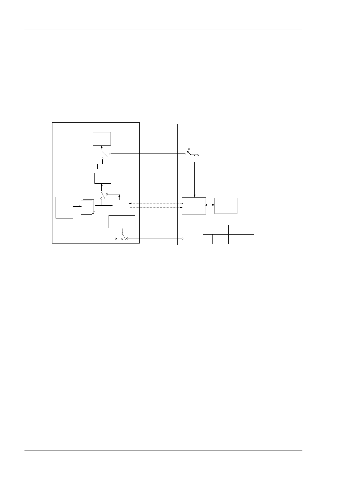
1.7 DIMAQ-IP
The DIMAQ-IP shown in Figure 2-1 is a Pentium III based post-processing unit that
employs the Windows 2000 operating system. The DIMAQ-IP acquires and stores
images (NTSC and PAL) for image and clip store, review, archive, print, and postprocessing applications. It support supports cine clips functions and other software
options such as Stress Echo.
Images travel to and from the host module to the DIMAQ-IP as 16-bit color in YBR
422 format over a 800 Mbit per second serial cable. Keyboard, trackball, and
messaging controls travel to and from the host module over a dedicated internal
Ethernet connection. Depending upon the application requirements, the DIMAQ-IP
can send images back to the host module over the serial cable, or send them to the
monitor through a software controlled switch.
The DIMAQ-IP software contains an application interface layer (API). Because this
API operates between the applications (such as Stress-echo, etc.) and the system
software, it is possible to upgrade or replace the DIMAQ-IP software or the system
software individually.
Siemens 7482255 Rev 01 Page 7 of 16
October 2002
Component Locations
0
The DIMAQ-IP module contains a hard disk drive (HDD), a writable compact disc
(CD-R/W), universal serial bus (USB) ports, and external Ethernet ports. The USB
port supports only the Stress-Echo report printing applications; it cannot be used for
any other application. The external Ethernet port is inactive and is reserved for
future applications.
Host Module DIMAQ-IP
SDRC
SDRC
ASIC
ASIC
G 60 S Host Box
G 60 S Host Box
Omina X/XS
Omina X/XS
Display
Display
DAC
DAC
TBCC
TBCC
(FPGA)
(FPGA)
LUT
LUT
RGB
RGB
Figure 2-1 Host Module and DIMAQ-IP Circuits
PPCL
PPCL
PCB
PCB
Keyboard
Keyboard
Control Panel
Control Panel
(Serial Cable)
(Serial Cable)
Local
Local
USB + Ethernet
USB + Ethernet
Ethernet
Ethernet
(Standard on G60 S; Option on G5
DIMAQ-IP
DIMAQ-IP
IPPC
IPPC
SVGA Output
SVGA Output
VGA Output
VGA Output
SPCL PCB
SPCL PCB
(PCI Bus
(PCI Bus
Card)
Card)
System
System
Memory
Memory
USB Ethernet
USB Ethernet
HDD
HDD
CDR/W
CDR/W
2.0 Component Locations
Photographs in this section show the location of the major components of the G60 S
system. The actual location of components and modules does not vary between the
G50 and the G60 S.
Some visible differences exist between the G50 and the G60 S components.
Photographic comparisons of those G50 components that differ in appearance are
provided where relevant.
Spare part numbers for the two systems are different, though many of the visible
differences between the G50 and the G60 S are just differences of color; see
Figure 2-4 and Figure 2-5. Spare parts are listed in "Spare Parts" (page C-1).
For a complete listing of all major components, see "Component Designations"
(page F-1). For a listing of the system spare parts, see "Spare Parts" (page C-1).
Page 8 of 16 7482255 Rev 01 Siemens
October 2002
 Loading...