

Page 1
SONOLINE G20 Ultrasound Imaging System
[2] Instructions for Use
Siemens Medical Solutions USA, Inc.
10031089-ABS-002-01
Page 2

SONOLINE G20
Ultrasound Imaging System
[2] Instructions for Use
Software Versions 1 and 2
Siemens Medical Solutions USA, Inc.
Ultrasound Division
1230 Shorebird Way
Mountain View, CA 94043-1344
U.S.A.
(800) 498-7948
(650) 969-9112
CE Declaration
This product is provided with a CE marking in accordance with the
regulations stated in Council Directive 93/42/EEC of June 14, 1993
concerning Medical Devices. Siemens Medical Solutions USA, Inc., is
certified by Notified Body 0123 to Annex II.3 – Full Quality System.
Authorized EC Representative:
Siemens Aktiengesellschaft
Medical Solutions
Henkestraße 127
D-91052 Erlangen
Germany
©2004-2005 Siemens Medical Solutions USA, Inc.
All Rights Reserved.
February 2005
Manuals distributed from the Federal Republic of Germany or Japan are printed in the
Federal Republic of Germany.
Manuals distributed from the United States of America are printed in the
United States of America.
SONOLINE G20, ReadySet, TGO, THI, MultiHertz, DIMAQ, microCase, SynAps, QuickSet,
SuppleFlex, and Evolve Package are trademarks of Siemens Medical Solutions USA, Inc.
Windows, CIDEX, CIDEX Plus, CIDEX OPA, Milton, Virkon, and Gigasept FF are
registered trademarks of their respective owners.
Siemens reserves the right to change system specifications at any time.
[2] INSTRUCTIONS FOR USE i
Page 3

About This Manual
The Instructions for Use consists of two volumes:
[1] Instructions for Use
The [1] Instructions for Use includes both a general overview and a
technical description of the ultrasound imaging system. This manual
contains detailed information on the safety and care of the ultrasound
system and its transducers. A chapter is dedicated to the description of
all system controls. The [1] Instructions for Use also includes the
procedures for system setup and beginning an exam.
[2] Instructions for Use
The [2] Instructions for Use includes procedures for acquiring and
optimizing images. This manual provides procedures for general and
exam-specific measurements and calculations.
The System Reference provides reference information for the ultrasound
imaging system.
ii [2] INSTRUCTIONS FOR USE
Page 4

Conventions
Conventions used throughout this manual are listed below. Take a moment
to familiarize yourself with these conventions.
Cross-References
This manual provides you information by topic. When additional information
exists within this or other manuals, a reference graphic and the name of the
book is provided in the right column. If the information exists within the
chapter, a cross-reference to the page number is listed. Otherwise,
information is referenced by chapter number.
System Presets
You can use the options and settings available in the system presets menu
to set up the ultrasound system with your preferences. Presets define the
configuration of the system software whenever you power on the system.
A complete listing of system presets is located in the System Reference.
Whenever a system preset is discussed in other chapters or in the User and
Reference Manuals, a graphic is provided in the right column.
The graphic identifies a preset option or setting in the system presets menu
that is available for you to customize your ultrasound system. The name of
the category on the menu containing the system preset is listed for
your convenience.
[1] Instructions for Use
Screen Saver Ch 1
Intended Use Ch 1
[2] Instructions for Use
Imaging Functions Ch A1
System Reference
Accessories
and Options Ch 2
F6
Default Settings
► Automatic Freeze
Response
[2] INSTRUCTIONS FOR USE iii
Page 5

Warnings, Cautions, and Notes
WARNING: Warnings are intended to alert you to the importance of following
the correct operating procedures where risk of injury to the patient or system
user exists.
Caution: Cautions are intended to alert you to the importance of following
correct operating procedures to prevent the risk of damage to the system.
Note: Notes contain information concerning the proper use of the system and/or correct
execution of a procedure.
Control Panel Keys, Controls, and Menu Selections
Keys and controls located on the control panel are identified by uppercase,
boldface type.
Example: Rotate the DEPTH/ZOOM control.
Function keys located on the keyboard are identified by the number of the
function key.
Example: Press the F6 key.
Menu selections are indicated with the name of the selection in
boldface type.
Example: Select Next to access the second page of on-screen
menu selections.
iv [2] INSTRUCTIONS FOR USE
Page 6

Selection of On-Screen Objects
The SET key on the control panel functions as a point-and-select device
(similar to a computer mouse) when used with the trackball. To select an
on-screen object such as a button or a X symbol, roll the trackball to
position the pointer (cursor) on the object and then press the SET key on
the control panel.
In this manual, the term "select" or "click" describe the trackball and SET key
action required to select an on-screen object. In the example below,
phrases A, B, C, and D are equivalent actions.
A. Roll the trackball to the Search button and then press the SET key.
B. Select the Search button.
C. Click the Search button.
D. Click Search.
Special Terms and Menu Options
Special terms are indicated in boldface italics and are accompanied by a
brief description on their first use in the manual.
Example: Provides on-screen anatomical graphics of
indicate the anatomy under evaluation.
Within a procedure, options in the system presets are identified in text as
boldface type.
Example: Highlight the Keyboard – Annotation option.
pictograms
that
[2] INSTRUCTIONS FOR USE v
Page 7

Table of Contents
[2] Instructions for Use
Chapter Title Chapter Description
Chapter A1
Imaging Functions
Procedures for general imaging functions, including Annotations and how
to create QuickSets™.
Chapter A2
2D-Mode and M-Mode
Imaging Functions
Chapter A3
CINE
Chapter A4
Biopsy
Chapter B1
Measurements
and Calculations
Chapter B2
Obstetrical Measurements
Description of the imaging functions for 2D-mode and M-mode imaging.
Includes an explanation of the Ensemble™ Tissue Harmonic Imaging
option.
Information on how to review CINE data, either frame by frame or as a
continuous display.
Description of the biopsy (puncture) guidelines on the ultrasound system,
including the needle path verification procedure.
Step-by-step procedures for using the Measurement function. The
procedures that apply to all exam types, including the report feature, are
described first.
Description of the features and calculations specific to the Obstetrical
package, including fetal cardiac measurements.
and Calculations
Chapter B3
Emergency Medicine
Measurements
and Calculations
Description of the features and calculations specific to the Emergency
Medicine (EM) package, including the report-specific information for:
FAST (Focused Abdominal Sonography in Trauma)
Aorta
Gallbladder
Renal
Obstetric
Cardiac
Bladder
DVT (Deep Vein Thrombosis).
Chapter B4
Urology and Rectal
Description of the features and calculations specific to the Urology and
Rectal packages.
Measurements
and Calculations
Chapter B5
Cardiac Measurements
and Calculations
Chapter C1
Description of the features and calculations specific to the Cardiac
package. All measurement functions for a Cardiac exam are detailed in this
chapter.
Attachment procedures for transducer accessories.
Transducer Accessories
Chapter C2
Endo-V II Transducer
Chapter C3
Endo-P II Transducer
Note: Not all features and options described in this publication are available to all users.
Please check with your Siemens representative to determine the current availability of
features and options.
Description of the Endo-V II transducer and the Endo-V II needle guide
bracket kit.
Description of the Endo-P II transducer and the Endo-P II needle guide
bracket kit.
vi [2] INSTRUCTIONS FOR USE
Page 8

A1 Imaging Functions
Annotation .......................................................................................................... 3
Direct Text Entry............................................................................................ 4
Labels for Position and Anatomical Structures .............................................. 5
Directional Arrows ......................................................................................... 6
Pictograms .................................................................................................... 7
QuickSet Feature................................................................................................ 8
Creating a QuickSet....................................................................................... 8
Activating a QuickSet .................................................................................. 10
Saving a QuickSet........................................................................................ 10
2D-Mode and M-Mode QuickSets............................................................... 11
[2] INSTRUCTIONS FOR USE
A1 - 1
Page 9

A1 Imaging Functions
A1 - 2 [2] INSTRUCTIONS FOR USE
Page 10

A1 Imaging Functions
Annotation
You can use four methods to annotate an image.
Direct text entry using the keyboard
Predefined labels for positions and anatomical structures
Pictograms of anatomical structures
Arrow keys
System Reference
System Presets Ch 3
To remove annotation from the image screen, use the F12 key. You can
program the system to automatically delete on-screen annotation each time
you use the FREEZE key to unfreeze the image. Use the system presets to
specify whether all text or all pictograms are deleted at unfreeze.
The default position for the annotation cursor on the image screen is in the
location defined by theF11(Home Set) key.
Once you have annotated an image during a patient examination, the
system remembers the last position of the cursor; press the SELECT
control to redisplay the annotation cursor.
To reposition an annotation:
1. During the annotation function, roll the trackball to position the cursor
on the text, label, or arrow.
2. Press the SET key to select the annotation.
3. Roll the trackball to reposition the annotation and then press the
SET key.
To delete a single annotation:
1. During the annotation fuction, roll the trackball to position the cursor on
the text, label, or arrow.
2. Press the SET key to select the annotation.
3. Press the F12 key on the keyboard.
F4
General
►Delete Text
on Unfreeze
General
►Delete Pictogram
on Unfreeze
To change the font size:
1. During the annotation function, select the menu category at the top of
the menu and then select Others.
2. Select Font Size and rotate the SELECT control or press the SET key to
display the desired setting.
The system applies the selected setting to direct text entry and
annotation labels. The new font size does not affect existing
annotations.
3. To exit the menu, press the MENU key or the TEXT key.
To hide text:
Press the F13 key to toggle the display of the text on or off.
[2] INSTRUCTIONS FOR USE A1 - 3
Page 11

A1 Imaging Functions
Direct Text Entry
Use the keyboard to enter text directly onto the image area.
To activate text entry:
1. Press the TEXT key on the control panel.
The system places the text cursor on the image screen.
2. To reposition the text cursor, roll the trackball.
3. Use the keyboard to enter text.
4. To exit the text entry function, press the TEXT key on the control panel.
To exit the text entry function and delete all text, press the ESCAPE key
on the control panel.
A1 - 4 [2] INSTRUCTIONS FOR USE
Page 12

A1 Imaging Functions
Labels for Position and Anatomical Structures
Each exam type has labels for anatomical structures, imaging views, and
body positions that can display as onscreen selections when the exam type
is active. The labels are stored in libraries. Use the system presets to
customize the text for anatomical structures, for imaging views and for
body positions. You can:
Add, replace, or delete onscreen menu labels
System Reference
System Presets Ch 3
Change the spelling or abbreviation of the labels
Establish the order in which the labels display in the onscreen menu
Reset the library to the original system-defined labels
To annotate using a predefined label:
1. During the annotation function, roll the trackball to position the text cursor
at the location for a label to display and then press the MENU key.
2. Select the menu category at the top of the menu and then select
Anatomy or Position.
The system displays the list of labels corresponding to the selected menu
category.
3. Select the required label and then press the SET key.
The system inserts the label at the cursor's position.
4. For each additional label, reposition the cursor, select another label, and
press the SET key.
Note: You can place a combined total of 24 labels and arrows on the image screen.
5. To delete the last label from the screen, press the F12 key on the
keyboard. Each press of the F12 key deletes a previous label. To delete
all annotations from the screen, press the F14 key.
6. Press the TEXT key on the control panel to exit annotation. Press the
ESCAPE key to exit and delete the labels.
F6
Default Settings
►Text Annotation
►► Anatomy or Position
[2] INSTRUCTIONS FOR USE A1 - 5
Page 13

A1 Imaging Functions
Directional Arrows
You can place arrows on-screen by first pressing the TEXT key on the
control panel or the F9 key on the keyboard.
To place an arrow on the image screen:
1. Press the F9 key.
The system displays an arrow on the image screen.
2. Roll the trackball to position the cursor at the required location for
the arrow.
Note: If you are adding an arrow immediately after entering text or a label, roll the
trackball away from the text before adding the arrow.
Note: You can place a combined total of 24 labels and arrows on the image screen.
3. To change the direction of the arrow, rotate the SELECT control on the
control panel.
4. To change the size of the arrow, select Arrow Size in the Others
menu.
Note: If the menu is not displayed, select the menu category at the top of the menu
and then select Others.
5. To save changes to the arrow's direction and size, press the SET key.
6. To delete an arrow, press the F12 (Delete Word) key.
7. To exit the arrow function and retain all the arrows and labels, press the
F9 key on the keyboard or the TEXT key on the control panel. To exit
the arrow function and erase all arrows and labels, press the
ESCAPE key.
A1 - 6 [2] INSTRUCTIONS FOR USE
Page 14

A1 Imaging Functions
Pictograms
Pictograms are graphics that display on-screen to indicate the anatomical
structure under evaluation and to indicate the orientation of the transducer
to the structure. You can rotate fetal pictograms to indicate the orientation
of the fetus in utero.
System Reference
System Presets Ch 3
Use the system presets to assign pictograms to each exam type. When the
exam is active, pressing the PICTOGRAM key causes the assigned
pictograms to display at the bottom of the image screen. One pictogram
can display on an image. In Dual-mode and 4B-mode, you can display one
pictogram for each image.
The selected pictogram for an image will display until you press the
ESCAPE key, select a new pictogram, or begin a new exam. Use the
system presets to automatically remove a pictogram when you unfreeze an
image.
To display a pictogram:
1. Press the PICTOGRAM key.
The system displays the available pictograms for the active exam type.
2. To select a pictogram, roll the trackball to outline the pictogram and
then press the SET key.
The selected pictogram displays with a transducer orientation indicator
in the lower left of the image.
3. Roll the trackball to position the transducer orientation indicator.
a. To rotate the indicator, rotate the SELECT control.
b. To anchor the position of the indicator, press the SELECT control.
4. To rotate a fetal pictogram, press and then rotate the SELECT control.
5. To redisplay the list of pictograms, press the MENU key.
6. To remove a pictogram from the screen, press the ESCAPE key while
the trackball is assigned to the pictogram function.
F6
Default Settings
►Pictogram List
General
►Delete Pictogram
on Unfreeze
[1] Instructions for Use
Trackball
assignment Ch 3
[2] INSTRUCTIONS FOR USE A1 - 7
Page 15

A1 Imaging Functions
QuickSet Feature
The QuickSet™ feature allows you to capture an optimized configuration of
imaging parameter settings for a specific transducer and exam. The system
stores this configuration in a file known as a
When a QuickSet is selected as the current exam type, the system
activates the associated transducer and resets all imaging functions
according to the stored configuration.
Use the system presets to change the default settings for an
existing QuickSet.
QuickSet
Creating a QuickSet
You can have a maximum of 32 QuickSets on the system at one time. If you
attempt to create a new QuickSet, or load a saved QuickSet from disk after
the maximum of 32 is reached, the system requires you to delete one or
more existing QuickSets to accommodate the new ones.
To create a QuickSet:
1. Adjust the image parameter settings as required and then press the
F8 function key on the keyboard.
.
System Reference
System Presets Ch 3
F6
QuickSet Parameters
The system displays a screen for saving and deleting QuickSets.
2. Roll the trackball to the QuickSet Name field and then press the
SET key.
3. Use the keyboard to enter up to 20 characters for the name of
the QuickSet.
4. Save the name by either rolling the trackball to the Save button and
pressing the SET key or by pressing the ENTER key on the keyboard.
The system displays the image screen and activates the QuickSet
you created.
A1 - 8 [2] INSTRUCTIONS FOR USE
Page 16

A1 Imaging Functions
To overwrite an existing QuickSet with the current image
parameter settings:
1. Adjust the image parameter settings as required and then press the
F8 function key.
The system displays a screen for saving and deleting QuickSets.
2. Roll the trackball to an existing QuickSet and then press the SET key.
3. Roll the trackball to the Save button and then press the SET key.
The system displays a message asking if you want to overwrite
the QuickSet.
4. Roll the trackball to the OK button and then press the SET key to assign
the new QuickSet configuration to the existing name.
To delete an existing QuickSet:
1. Press the F8 function key.
The system displays a screen for saving and deleting QuickSets.
2. Roll the trackball to an existing QuickSet and then press the SET key on
the control panel.
3. Roll the trackball to the Delete button and then press the SET key on
the control panel.
The system removes the highlighted name from the list of QuickSets. If
you attempt to delete a QuickSet when it is the current exam type, the
system displays a message stating that you cannot delete a QuickSet
currently loaded on the system.
[2] INSTRUCTIONS FOR USE A1 - 9
Page 17

A1 Imaging Functions
Activating a QuickSet
A QuickSet is a user-defined variation on a system-defined exam type.
To select a QuickSet exam type:
1. Press the F5 function key to access the Exam & QuickSet List.
2. Roll the trackball to the name of a QuickSet.
3. Press the SET key.
Note: When a QuickSet is selected as the current exam type, the system activates the
associated transducer and resets all imaging functions according to the stored
configuration.
Saving a QuickSet
You can save a QuickSet to a disk using the Preset/QuickSet utilities.
System Reference
System Presets Ch 3
Disk Function Ch 4
Preset/QuickSet
Utility Ch 5
F6
Customize Keys
A1 - 10 [2] INSTRUCTIONS FOR USE
Page 18

A1 Imaging Functions
2D-Mode and M-Mode QuickSets
A QuickSet includes the following 2D-mode and M-mode parameters:
2D-mode M-mode
Gain
Persistence
Gray Map
Dynamic Range
Edge Enhancement
Field of View
Transmit Power
Depth (mm)
Line Density
Focal Zones
Initial Frequency (MHz)
Rotate
Flip (L/R)
Reject
Res/Speed
Scan Angle (Endo-V II transducer)
SynAps (Synthetic Aperature)
Frequency
Steer
Focus
THI (Tissue Harmonic Imaging)
settings
Sweep Rate
Dynamic Range
Edge Enhancement
Reject
Gain
Gray Map
Transmit Power
[2] INSTRUCTIONS FOR USE A1 - 11
Page 19

A1 Imaging Functions
A1 - 12 [2] INSTRUCTIONS FOR USE
Page 20

A2 2D-Mode and M-Mode Imaging Functions
Activating 2D-Mode ........................................................................................... 3
Imaging Menu ............................................................................................... 3
2D-Mode Formats ......................................................................................... 4
Mixed-Mode Formats............................................................................. 4
Active Image .......................................................................................... 4
Activating Split Mode .................................................................................... 5
Activating Dual-Mode .................................................................................... 6
Activating 4B-Mode....................................................................................... 7
Activating A-Mode......................................................................................... 8
Activating M-Mode........................................................................................ 9
Simultaneous Format ............................................................................. 9
M-Mode Formats ................................................................................... 9
2D/M-Mode Display and Update.......................................................... 10
Changing the M-Mode Sweep ............................................................. 11
2D/M-Mode Example Screen Layout............................................................ 12
Imaging Parameters Legend........................................................................ 12
Imaging Parameters ......................................................................................... 13
Changing a Transducer Frequency .............................................................. 14
Changing the Imaging Depth....................................................................... 14
Adjusting the Overall System Receiver Gain ............................................... 15
Adjusting the Depth Gain Compensation (DGC).......................................... 16
Changing the Dynamic Range ..................................................................... 17
Adjusting the Focus..................................................................................... 18
Single Focal Zone ................................................................................. 18
Multiple Focal Zones ............................................................................ 18
[2] INSTRUCTIONS FOR USE A2 - 1
Page 21

A2 2D-Mode and M-Mode Imaging Functions
Changing the Line Density........................................................................... 19
Maximizing Resolution and Speed............................................................... 20
Synthetic Aperture....................................................................................... 20
Changing the Persistence............................................................................ 21
Changing the Edge Enhancement ............................................................... 21
Selecting a Gray Map .................................................................................. 22
Modifying a Gray Map.......................................................................... 22
Reject for 2D-Mode and M-Mode ........................................................ 24
Adjusting the Field of View .................................................................. 24
Changing the Image Orientation.................................................................. 26
Horizontal Orientation........................................................................... 26
Vertical Orientation............................................................................... 27
Offsetting the Image ................................................................................... 28
Magnifying the Image.................................................................................. 29
Magnifying Split Images....................................................................... 30
Magnifying a Dual Image...................................................................... 30
Magnifying 2D/M-Mode Images........................................................... 31
Ensemble Tissue Harmonic Imaging .............................................................. 32
Optimizing Contrast Resolution and Brightness Uniformity (TGO) ............ 33
A2 - 2 [2] INSTRUCTIONS FOR USE
Page 22

A2 2D-Mode and M-Mode Imaging Functions
Activating 2D-Mode
2D-mode is the default imaging mode for the ultrasound system.
2D indicates two-dimensional (2D) grayscale imaging. When you first
power on the system, 2D-mode is active.
To access 2D-mode from another imaging mode:
Press the 2D control on the control panel.
The system displays in 2D-mode (full screen).
Note: When operating in mixed modes (for example, 2D-mode with M-mode), pressing
the 2D control deactivates M-mode and displays full-screen 2D-mode imaging.
Imaging Menu
During 2D-mode or M-mode imaging, you can use selections in the Imaging
menu to adjust the settings for imaging parameters.
To display the 2D-mode Imaging menu:
1. Press the MENU key on the control panel.
The system displays the default menu or the menu last viewed.
2. To change the displayed menu, roll the trackball to highlight the menu
category at the top of the menu on the left of the screen.
Example: M X.
The system displays the list of available menu categories. If the image
is live, the CINE menu is not available.
3. Roll the trackball to 2D and then press the SET key.
The system displays the 2D-mode menu.
4. Adjust imaging parameters using selections in the menu using the
trackball with the SELECT control or SET key located on the
control panel.
5. Continue adjusting imaging parameters and then press the MENU key
to exit the menu.
[2] INSTRUCTIONS FOR USE A2 - 3
Page 23
A2 2D-Mode and M-Mode Imaging Functions
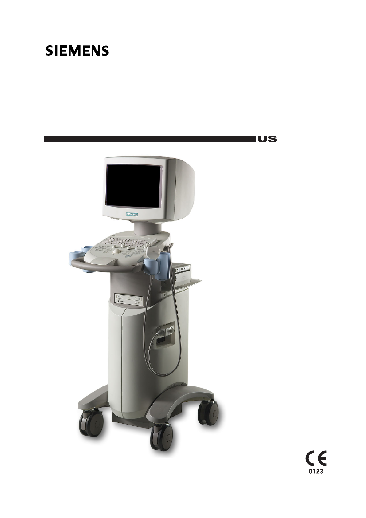
2D-Mode Formats
You can display 2D-mode images in different formats: Split, Dual and
4B modes. Imaging capability in 2D-mode, M-mode, A-mode, and mixed
modes is available.
Mixed-Mode Formats
2D/M-mode
Active image
indicator.
Active Image
In Split, Dual, and 4B modes, while more than one 2D-mode image displays
on the monitor, you can adjust imaging parameters for one image at a time.
active
This image is the
the active image indicator.
Standard 2D-mode. Dual-mode. 4B-mode.
Split (B+B) mode. 2D-mode with A-mode.
image. The system indicates the active image with
Inactive image
indicator.
A2 - 4
[2] INSTRUCTIONS FOR USE
Page 24

A2 2D-Mode and M-Mode Imaging Functions
Activating Split Mode
Split mode creates side-by-side images from one 2D-mode image. The two
images are simultaneously frozen or real-time. Split mode is available with
all transducers.
When you first initiate Split mode, the image parameter settings from the
previous mode are applied to both images. Certain imaging parameters
(such as Gray Map, A-mode, Reject, and Modify Map) can be changed in
the right image, allowing comparison of the effects of different image
settings on an anatomical structure.
To activate Split mode:
1. From a 2D-mode image display, press the SPLIT key on the
control panel.
The left image is the reference image.
2. To display the full-screen 2D-mode image, press the SPLIT key or the
2D control on the control panel.
3. To simultaneously freeze both images, press the FREEZE key on the
control panel.
4. To exit Split mode, press the 2D control.
[2] Instructions for Use
Imaging
Parameters A2-13
[2] INSTRUCTIONS FOR USE A2 - 5
Page 25

A2 2D-Mode and M-Mode Imaging Functions
Activating Dual-Mode
In Dual-mode, two acquired 2D-mode images display side-by-side on the
image screen. Both images are obtained separately, and only one image
displays in real-time.
When you first activate Dual-mode, the imaging settings from the previous
mode are applied to the first image. The second image retains the same
settings as the first image.
You cannot activate M-mode while Dual-mode is active. You cannot activate
Dual-mode while 2D/M-mode is active.
To activate Dual-mode:
1. Press the left DUAL/SELECT key on the control panel to display an
image on the left side of the screen, or press the right key to display
an image on the right side of the screen.
Only one image can be active at a time. The active image is indicated
by the lighting intensity of the selected key and by the active
image indicator.
2. To generate a second image, press the other DUAL/SELECT key.
The system freezes the active image and activates a second image.
3. To display a full screen image, press the key for the active image a
second time. Press the key again to restore the side-by-side display.
[2] Instructions for Use
Imaging
Parameters A2-13
4. To inactivate the current image and activate the other image in a
side-by-side display, press the DUAL/SELECT key.
The system shifts the active image indicator to the selected image
and freezes both images.
5. Press the FREEZE key to unfreeze the Dual-mode display.
6. To exit Dual-mode, press the 2D control on the control panel.
A2 - 6 [2] INSTRUCTIONS FOR USE
Page 26

A2 2D-Mode and M-Mode Imaging Functions
Activating 4B-Mode
In 4B-mode, four separately acquired 2D-mode images display on the image
screen. Only one image can display in real-time.
When you first activate 4B-mode, the imaging settings from the previous
mode are applied to the first image. Subsequent images retain the same
settings as the previous image.
To activate 4B-mode:
1. From a 2D-mode display, press the 4B key on the control panel.
The first image displays in the upper left quadrant of the screen. This is
the active image, as identified by the brightened active image indicator.
2. Press the FREEZE key.
The image is frozen in position and a second image displays in the next
available quadrant.
3. To continue to place images, press the FREEZE key.
4. To cycle through the images, first freeze the active image and then
press the 4B key. To display the active image in real-time, unfreeze
the system.
5. To exit 4B-mode, press the 2D control.
[2] INSTRUCTIONS FOR USE A2 - 7
Page 27

A2 2D-Mode and M-Mode Imaging Functions
Activating A-Mode
Important: At the time of publication, A-mode was not cleared for use by the U.S. Food
and Drug Administration. Before using A-mode, check the current regulations for the
country in which you are using this system to determine if A-mode is cleared for use.
A-mode is available in 2D-mode. A-mode displays in real-time or displays on
a frozen image.
Once activated, A-mode displays even when you change modes. If you
enter into a mode that does not support A-mode, the A-mode display is
removed. When you activate a mode that does support A-mode, the
display and cursor return.
To display A-mode:
1. Press the MENU key on the control panel to display the 2D-mode
Imaging menu when 2D-mode is active.
2. Roll the trackball to A-mode on the 2D-mode menu and press the
SET key to toggle the setting to On.
The system places an A-mode cursor in the image. The location of the
cursor designates the region of sampling.
3. Roll the trackball to position the cursor on the image.
The echo amplitude displays along the depth scale on the image.
4. To remove A-mode from the image, highlight A-Mode in the 2D-mode
Imaging menu and then press the SET key to toggle the setting to Off.
5. Continue adjusting imaging parameters and then press the MENU key
to exit the menu.
A2 - 8 [2] INSTRUCTIONS FOR USE
Page 28
A2 2D-Mode and M-Mode Imaging Functions
Activating M-Mode
When you first activate M-mode, the M-mode cursor displays on the
2D-mode image. This cursor is a graphical representation of the acoustic
line along which the M-mode information is gathered. The cursor displays
as a row of dots representing depth.
Simultaneous Format
During 2D/M-mode, the 2D-mode image and M sweep display
simultaneously in real-time or are simultaneously frozen.
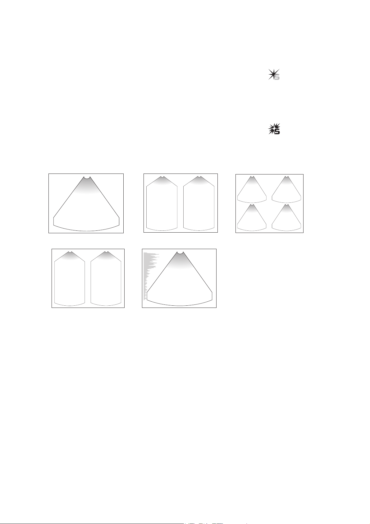
M-Mode Formats
Use the system presets to select your preference of a 2D/M-mode
imaging format.
½-½ horizontal. 40/60 vertical.
System Reference
System Presets Ch 3
F6
Default Settings
► 2D/M Display Format
1/3-2/3 horizontal. Full Screen (M-Mode Imaging menu Selection).
[2] INSTRUCTIONS FOR USE A2 - 9
Page 29

A2 2D-Mode and M-Mode Imaging Functions
2D/M-Mode Display and Update
Curved array and linear array transducers allow a 2D-mode image and an
M-mode sweep to display simultaneously in real-time.
To activate M-mode, 2D/M-mode, or Split/M-mode:
Prerequisite: For Split/M-mode, you must use the system presets to select either the
1/3 – 2/3 or ½ – ½ display format.
1. Press the M key on the control panel.
Note: If the cursor bypass is selected in the system presets, the system activates
2D/M-mode immediately; proceed to step 4. If the cursor bypass is not selected,
the system initially displays an M cursor on the 2D-mode image.
The M
cursor
is a graphical representation of the acoustic line along
which M-mode information is gathered.
2. Roll the trackball to position the M cursor.
3. To activate 2D/M-mode, press the M key a second time.
The system displays a 2D-mode image and an M-mode sweep in the
format selected in the system presets. Use the trackball to reposition the
M-mode cursor on the 2D-mode image.
4. To activate Split/M-mode, first activate 2D/M-mode and then press the
SPLIT key on the control panel.
The system displays two 2D-mode images with the M-mode sweep.
5. To display a full-screen M-mode sweep, display the M-mode Imaging
menu, roll the trackball to Full M and then press the SET key to toggle
Full M with 2D/M.
Note: While a 2D/M-mode display is in freeze, you can press the left
DUAL/SELECT key to toggle a full-screen 2D-mode display on or off, and you can
press the right DUAL/SELECT key to toggle a full-screen M-mode display on or off.
System Reference
System Presets Ch 3
F6
Imaging
► Update Frames
in 2D/M
Default Settings
► 2D/M Display Format
Default Settings
► Bypass M Cursor
Display
6. To exit full-screen M-mode or 2D/M-mode, press the 2D control on the
control panel.
A2 - 10 [2] INSTRUCTIONS FOR USE
Page 30

A2 2D-Mode and M-Mode Imaging Functions
Changing the M-Mode Sweep
You can adjust the scrolling speed of the M-mode sweep, activate time
markers on the sweep, and specify sweep offset.
Scrolling Speed
You can choose from four sweep speeds: 2sec, 4sec, 8sec, and 16sec.
The sweep rate displays in the lower left of the sweep.
The sweep scrolls from the left of the image screen to the right.
To adjust the scrolling speed of the M-mode sweep:
1. Display the M-mode Imaging menu.
2. Roll the trackball to Sweep Sp.
3. Rotate the SELECT control or press the SET key to adjust the setting.
4. Continue adjusting imaging parameters and then press the MENU key
to exit the menu.
Time Markers
Time markers are available for display in the M-mode sweep. Use the
system presets to activate the markers. The vertical markers display in
intervals in a fixed location on the sweep.
Offset
In 2D/M-mode with a 1/3-2/3 or 1/2-1/2 horizontal sweep, you can offset
the 2D-mode image and the M-mode sweep to display specific information
more fully on-screen.
System Reference
System Presets Ch 3
F6
Display
► Time Marker Display
Default Settings
► 2D/M Display Format
[2] Instructions for Use
Offset A2-28
[2] INSTRUCTIONS FOR USE A2 - 11
Page 31

A2 2D-Mode and M-Mode Imaging Functions
2D/M-Mode Example Screen Layout
The active exam type, transducer, transducer frequency, frames per second,
and line density display in the upper left of the image screen. The values of
particular imaging parameters display by imaging mode at the bottom of the
image screen in the
Imaging Parameters
.
When Dual-mode or 4B-mode is selected, the values display only for the
active image. If the image is frozen, the values indicate the setting at the
time the image was in real-time. If the system is in 2D/M-mode, both the
2D settings and the M settings are displayed.
SIEMENS
.....
....
B
.....
Gyn
C5-2 3.5
FPS 43s
11:39:36 Th 05/29/2xxx
..........
0
.....
4sec
2D 60/1/24 M 40/2/13
MI 0.8 V 100%
Example of screen layout in 2D/M-mode.
90
....
B
[1] Instructions for Use
Transmit Power Ch 2
MI/TI Indices Ch 2
1 Imaging depth in mm
2 Active image indicator
3 Offset value (in mm) –
displays when
Offset is On
4 M-mode cursor
5 Focal zone marker
6 Gray bar
7 M-mode Imaging
Parameters indicating
dynamic range, edge
enhancement, and gain
8 Transmit Power and
MI/TI indices
9 2D-mode Imaging
Parameters indicating
dynamic range, edge
enhancement, and gain
10 Sweep rate
11 DGC curve
12 Location of Imaging
menu
13 Frames per second and
line density
14 Active transducer
name and frequency
15 Active exam type
Imaging Parameters Legend
2D: 60 / 1 / 24 = 2D-mode: Dynamic Range / Edge Enhancement / Gain
M: 40 / 2 / 13 = M-mode: Dynamic Range / Edge Enhancement / Gain
A2 - 12 [2] INSTRUCTIONS FOR USE
Page 32

A2 2D-Mode and M-Mode Imaging Functions
Imaging Parameters
When the system displays multiple images, changing the imaging
parameters may affect all images or only the active image.
Note: Frequency, line density, and scan width are transducer-dependent. Also, full-screen
M-mode does not support the functions that apply only to 2D-mode images.
Imaging Parameters
Dual-mode Split-mode 4B-mode 2D/M-mode
Parameter
Transmit Power
2D Gain
Depth
Depth Gain
Compensation
Focus
Frequency
M Gain
L/R Flip
Scan Width
Transducer type
Rotate
Zoom (Magnify)
Dynamic Range
Persistence
Edge
Res/Speed
Reject
Steer
FOV/POS
Offset
Gray Map
Line Density
SynAps
THI
2D-mode
Active Both Active Both Active All 2D M
[2] Instructions for Use
Creating a
QuickSet Ch A1
System Reference
System Presets Ch 3
[2] INSTRUCTIONS FOR USE A2 - 13
Page 33

A2 2D-Mode and M-Mode Imaging Functions
Changing a Transducer Frequency
Use the MULTIHERTZ control to change the operating frequency of
an active transducer.
The system displays the name of the active transducer and operating
frequency in the upper left of the image screen.
C4-2 3.5
Example of active transducer and operating frequency.
Note: During THI imaging, the system displays the frequency followed by a T.
C4-2 4.2T
Example of active transducer and operating frequency for THI imaging.
To change the transducer frequency:
Push the MULTIHERTZ control on the control panel up to increase
the frequency or down to decrease the frequency.
Selecting a higher frequency typically increases resolution,
whereas selecting a lower frequency improves penetration.
Changing the Imaging Depth
Maximum and minimum depth selections are dependent upon the
frequency of the transducer you are currently using. Depth is adjustable in
10-mm increments.
[2] Instructions for Use
THI A2-32
Use the system presets to assign the direction of rotation (clockwise
or counterclockwise) for increasing a value when using the
DEPTH/ZOOM control. This assignment affects both the depth and
zoom parameters.
A2 - 14 [2] INSTRUCTIONS FOR USE
Page 34

A2 2D-Mode and M-Mode Imaging Functions
To change the imaging depth:
Rotate the DEPTH/ZOOM control on the control panel.
The imaging depth displays at the bottom left of the image screen.
When you are using 2D-modes with more than one 2D-mode image, the
depth value displays for both 2D-mode images. In Split-mode, rotating
the DEPTH/ZOOM control changes the depth for both 2D-mode images.
In Dual-mode and 4B-mode, rotating the DEPTH/ZOOM control changes
the depth for the active image.
System Reference
System Presets Ch 3
F6
Customize Keys
► Zoom/Depth Direction
Adjusting the Overall System Receiver Gain
You can adjust the echo amplification and brightness of a 2D-mode image or
for an M-mode sweep. Rotating the 2D control changes the overall receiver
gain for the last active mode, 2D-mode or M-mode.
The range for gain is 0 dB to 40 dB in 1-dB increments. When combined
with the DGC Gain, a range of –15 dB to 55 dB is possible.
The gain value displays in the Imaging Parameters at the bottom of the
screen. When you are viewing Dual-mode or 4B-mode with more than one
image, the value displays only for the active image. In 2D/M-mode, separate
gain values display for the 2D-mode image and the M-mode sweep.
2D: 55/ 1/ 32 M: 35/ 2/ 29
Gain (dB) is indicated by the shaded value.
To adjust the overall gain for 2D-mode:
During 2D-mode imaging, rotate the 2D control on the control panel
clockwise to increase the gain or counterclockwise to decrease the gain.
To adjust the overall gain for M-mode:
During M-mode imaging, rotate the 2D control on the control panel
clockwise to increase the gain or counterclockwise to decrease the gain.
[2] Instructions for Use
Example Screen
Layout A2-12
[2] INSTRUCTIONS FOR USE A2 - 15
Page 35

A2 2D-Mode and M-Mode Imaging Functions
Adjusting the Depth Gain Compensation (DGC)
To compensate for weak signals or over-bright signals at various depths,
you can adjust Depth Gain Compensation (DGC) using the DGC slide
controls. The 2D control adjusts the overall receiver gain and compensates
for the brightness of the image.
The DGC provides eight slide controls for adjusting image quality during
real time imaging. Move each slide control to the right to increase the gain
or to the left to decrease the gain over a 30-dB range.
DGC Slide Controls.
Near Field
Center Field
Far Field
Use the system presets to turn on the display of the DGC curve. The curve
provides an on-screen representation of the DGC settings.
System Reference
System Presets Ch 3
F6
Display
►DGC Curve Display
General
► DGC Invert With
Image Invert
In 2D/M-mode, DGC adjustments affect both the 2D-mode image and the
M-mode sweep.
The DGC slide controls have no effect during CINE.
To adjust the DGC slide controls:
Move a slide control to the right to increase a setting or to the left to
decrease a setting.
A2 - 16 [2] INSTRUCTIONS FOR USE
Page 36

A2 2D-Mode and M-Mode Imaging Functions
Changing the Dynamic Range
You can adjust the overall contrast resolution of a 2D-mode image and the
overall contrast resolution of an M-mode sweep. For 2D-mode, the dynamic
range values are 35 dB to 70 dB in 1-dB increments. For M-mode, the same
range of values is available, but in 5-dB increments.
The dynamic range value displays in the Imaging Parameters at the bottom
of the screen. In Dual mode or 4B-mode with more than one image, the
value displays only for the active image. In 2D/M-mode, separate dynamic
range values display for the 2D-mode image and the M sweep.
2D: 55/ 1/ 32 M: 35/ 2/ 29
Dynamic range (dB) is indicated by the shaded value.
To change the dynamic range for 2D-mode:
1. Display the 2D-mode Imaging menu.
2. Roll the trackball to DR.
3. Rotate the SELECT control on the control panel to adjust the setting.
4. Continue adjusting imaging parameters and then press the MENU key
to exit the menu.
To change the dynamic range for M-mode:
1. Display the M-mode Imaging menu.
2. Roll the trackball to DR.
[2] Instructions for Use
Example Screen
Layout A2-12
3. Rotate the SELECT control on the control panel to adjust the setting.
4. Continue adjusting imaging parameters and then press the MENU key
to exit the menu.
[2] INSTRUCTIONS FOR USE A2 - 17
Page 37

A2 2D-Mode and M-Mode Imaging Functions
Adjusting the Focus
You can select the number of focal zones and then position their markers
on the image screen. Focal zone markers display on the left side of the
image area.
Curved array and linear array transducers support multiple transmit focus
points which you can select and position in the image.
Split images both have the same number and position of focal zones. In
Dual-mode and 4B-mode, it is possible to have a different number and
position of focal zones in each image. During M-mode, only one focal zone is
available.
Single Focal Zone
When you select one (1) focal zone, pushing the FOCUS control positions
the focal zone marker, regardless of scan depth.
Multiple Focal Zones
When you select two (2) or four (4) focal zones, the spacing between the
focal zones adjusts automatically. Pushing the FOCUS control adjusts the
relative position of the focal zone markers within the field of view. Available
positioning depends upon your selected depth.
Using multiple focal zones causes a reduction in the frame rate. The amount
of frame rate reduction depends on the depth of view and transducer.
To select the number of focal zones:
1. Display the 2D-mode Imaging menu.
2. Roll the trackball to Focus.
3. Rotate the SELECT control or press the SET key to adjust the setting.
4. To position the focal zones, push up or down on the FOCUS control on
the control panel.
5. Continue adjusting imaging parameters and then press the MENU key
to exit the menu.
A2 - 18 [2] INSTRUCTIONS FOR USE
Page 38

A2 2D-Mode and M-Mode Imaging Functions
Changing the Line Density
Use the Density 2D-mode Imaging menu selection to increase or decrease
the number of acoustic scan lines per frame for 2D-mode images. Increasing
the line density improves image detail and decreases the frame rate. Frame
rate is also dependent on the image width and the imaging depth.
The line density setting displays next to the frame rate in the upper left of
the image screen. Selections for line density are:
Menu Setting Definition Onscreen display
Std Standard s
Hi High h
To change the line density setting:
1. Display the 2D-mode Imaging menu.
2. Roll the trackball to Density. It may be necessary to access page 2 of
the menu.
3. Rotate the SELECT control or press the SET key to adjust the setting.
4. Continue adjusting imaging parameters and then press the MENU key
to exit the menu.
[2] Instructions for Use
Depth A2-14
Field of View A2-24
[2] INSTRUCTIONS FOR USE A2 - 19
Page 39

A2 2D-Mode and M-Mode Imaging Functions
Maximizing Resolution and Speed
You can adjust the balance between the scan line density (resolution) and
the synthetic aperture using the Res/Speed 2D-mode Imaging menu
selection.
Res/Speed
Setting
Std Std Off Full rate
Dtl High Off 1/2 rate
Far Std On 1/2 rate
To change the Res/Speed:
1. Display the 2D-mode Imaging menu.
2. Roll the trackball to Res/Speed.
3. Rotate the SELECT control to adjust the resolution and speed.
4. Continue adjusting imaging parameters and then press the MENU key
to exit the menu.
Line Density
(Resolution)
Synthetic
Aperture Frame Rate
Synthetic Aperture
Use the SynAps 2D-mode Imaging menu selection to increase the receiving
aperture by transmitting twice on the same image line. This technique
results in improved resolution, greater penetration at depth, and reduced
frame rate. The SynAps selection is available only when the Res/Speed
setting is Far.
To change the synthetic aperture:
1. Display the 2D-mode Imaging menu.
2. Confirm Far is selected for Res/Speed.
3. Roll the trackball to Syn/Aps. It may be necessary to access page 2 of
the menu.
4. Press the SET key to toggle the setting to On or Off.
5. Continue adjusting imaging parameters and then press the MENU key
to exit the menu.
A2 - 20 [2] INSTRUCTIONS FOR USE
Page 40

A2 2D-Mode and M-Mode Imaging Functions
Changing the Persistence
Persistence provides a visible smoothing effect to the 2D-mode image by
persisting lines of image data for each frame of imaging.
To change persistence:
1. Display the 2D-mode Imaging menu.
2. Roll the trackball to Persistence.
3. Rotate the SELECT control to adjust the setting.
4. Continue adjusting imaging parameters and then press the MENU key
to exit the menu.
Changing the Edge Enhancement
Use the Edge 2D-mode or M-mode Imaging menu selection to distinguish
the contours of a structure during real-time imaging. The range of values for
edge enhancement is from 0 (none) to 5 (maximum).
The edge enhancement value displays in the Imaging Parameters at the
bottom of the screen. In Dual mode and 4B-mode, the value displays only
for the active image. In 2D/M-mode, the value displays for both the
2D-mode image and the M-mode sweep.
2D: 55/ 1/ 32 M: 35/ 2/ 29
Edge enhancement is indicated by the shaded value.
To change edge enhancement:
1. Display the 2D-mode Imaging menu.
2. Roll the trackball to Edge.
3. Rotate the SELECT control to adjust the setting.
4. Continue adjusting imaging parameters and then press the MENU key
to exit the menu.
[2] Instructions for Use
Example Screen
Layout A2-12
[2] INSTRUCTIONS FOR USE A2 - 21
Page 41

A2 2D-Mode and M-Mode Imaging Functions
Selecting a Gray Map
During real-time imaging or when the system is in freeze, select the active
gray map
or processing curve by using the Gray Map Imaging menu
selection. The system assigns the echo amplitudes to gray levels according
to the selected gray map.
The active gray map is depicted by a gray bar, which displays on the right
side of the image screen. The gray bar represents the range of gray shades
available for the selected map.
To select a Gray Map:
1. Display the 2D-mode Imaging menu.
2. Roll the trackball to Gray Map.
3. Rotate the SELECT control to adjust the setting.
The label of the selected gray map also displays below the gray bar.
4. Continue adjusting imaging parameters and then press the MENU key
to exit the menu.
Modifying a Gray Map
Use the Modify Map 2D-mode Imaging menu selection to redistribute the
range of echo amplitudes assigned to the range of available gray shades for
the selected gray map. You can modify E, S, D, A, C, and B of the seven
available gray maps during real-time imaging or when the system is in
freeze. You can reposition the inflection points within a specific range. The
system automatically recalculates the curve and updates the image.
[2] Instructions for Use
Example screen
Layout A2-12
L
Example of a gray bar.
The ten inflection
points of a processing
curve. The cursor
displays as a box,
positioned here over
the second point.
A2 - 22 [2] INSTRUCTIONS FOR USE
Page 42

A2 2D-Mode and M-Mode Imaging Functions
To modify the map:
1. Display the 2D-mode Imaging menu.
2. Roll the trackball to Modify Map.
3. Rotate the SELECT control to adjust the setting.
The system overlays the selected map on the image screen.
4. Press the SELECT control on the control panel to activate the edit
feature for the selected map.
5. Rotate the SELECT control on the control panel to select an
inflection point.
6. Roll the trackball to reposition the inflection point.
7. Repeat steps 5 and 6 for each required inflection point.
8. After modifying the map:
To save the inflection point changes and continue modifying gray
maps, press the MENU key.
To save the inflection point changes and resume imaging, press the
ESCAPE key.
To restore factory defaults for the selected Gray Map:
1. Display the 2D-mode Imaging menu.
2. Roll the trackball to Reset Map.
3. Press the SET key to reset the map to factory default settings.
If the displayed map has been modified, the system prompts you
to confirm the action.
4. Select OK to re-establish factory default inflection points for the
selected map.
5. Continue adjusting imaging parameters and then press the MENU key
to exit the menu.
[2] INSTRUCTIONS FOR USE A2 - 23
Page 43

A2 2D-Mode and M-Mode Imaging Functions
Reject for 2D-Mode and M-Mode
Use the Reject 2D-mode or M-mode Imaging menu selection to eliminate
the display of echoes below a designated level. The selected level displays
on the gray bar from 0 (weak echoes) to 64 (strong echoes). Increasing the
level removes low to high amplitude signals, and decreasing the level
restores the display of high to low amplitude signals.
To establish a 2D-mode or M-mode range of echo amplitudes:
1. Display the 2D-mode Imaging menu.
2. Roll the trackball to Reject.
3. Rotate the SELECT control to adjust the setting.
4. Continue adjusting imaging parameters and then press the MENU key
to exit the menu.
Adjusting the Field of View
L
Example of a gray bar
with reject setting for
2D-mode.
You can optimize the
field of view
(FOV) during real-time imaging.
For curved array transducers, adjust the sector angle and position of
the image.
For linear array transducers, adjust the image width and steer the image
through the left, center, and right positions.
The actual angle of the field of view is determined by the geometry of
the transducer.
A2 - 24 [2] INSTRUCTIONS FOR USE
Page 44

A2 2D-Mode and M-Mode Imaging Functions
To adjust the field of view for a curved array transducer:
1. Display the 2D-mode Imaging menu.
2. Roll the trackball to FOV/POS.
3. Press the SET key to toggle the setting to On.
The system assigns the trackball to adjustment of the sector angle.
4. Roll the trackball to the left to decrease or to the right to increase the
sector angle of the image.
5. To reposition the field of view, press the SET key.
The system assigns the trackball to adjustment of the FOV position.
6. Roll the trackball to the right or to the left to reposition the field of view.
7. To exit FOV/POS adjustment, roll the trackball to FOV/POS and then
press the SET key.
To adjust the field of view for a linear array transducer:
1. Display the 2D-mode Imaging menu.
2. Roll the trackball to FOV/POS.
3. Press the SET key to toggle the setting to On.
The system assigns the trackball to adjustment of the image width.
4. Roll the trackball to adjust the width of the image.
5. To steer the image, press the MENU key and then roll the trackball
to Steer.
6. Rotate the SELECT control to adjust the setting.
The system steers the image through the left, right, and center
positions.
7. Continue adjusting imaging parameters and then press the MENU key
to exit the menu.
[2] INSTRUCTIONS FOR USE A2 - 25
Page 45

A2 2D-Mode and M-Mode Imaging Functions
Changing the Image Orientation
Change the scan direction of a transducer to horizontally flip a 2D-mode
image using the L/R FLIP key. You can also rotate the 2D-mode image or the
M-mode sweep so that the near field displays on the right, at the bottom, on
the left, or on the top of the image screen by pressing the SHIFT+L/R FLIP
keys. Each press of these keys rotates the image 90°.
Horizontal Orientation
The active image indicator shows the scan beginning point. You can change
the scan direction of a transducer by using the L/R FLIP key to toggle the
horizontal orientation of the image, for example, from right-to-left or
left-to-right.
Mode Effect of L/R
Split (B+B) mode Simultaneously reverses both images
Dual-mode, 4B-mode Reverses the active image only
To change the horizontal orientation of an image:
Press the L/R FLIP key on the control panel.
The system changes the direction of the scan.
Active image indicator.
A2 - 26 [2] INSTRUCTIONS FOR USE
Page 46

A2 2D-Mode and M-Mode Imaging Functions
Vertical Orientation
The conventional vertical orientation of an image is to display the near field
at the top of the image screen. You can change the display orientation so
that the near field displays at the right, bottom, or left of the image screen
by using the SHIFT+L/R FLIP keys.
System Reference
System Presets Ch 3
F6
General
►DGC Invert with
90° 180° 270°
Note: Use the system presets to determine if the DGC curve inverts when you press the
SHIFT+L/R FLIP keys.
Mode Effect of Rotate
Split (B+B) mode Simultaneously rotates both images
Dual-mode, 4B-mode Rotates the active image
To change the vertical orientation of an image:
Press the SHIFT+L/R FLIP keys on the control panel.
Image Invert
Each press of these keys rotates the image 90°.
[2] INSTRUCTIONS FOR USE A2 - 27
Page 47

A2 2D-Mode and M-Mode Imaging Functions
Offsetting the Image
Use the 2D-mode Offset Imaging menu selection while imaging in 2D-mode
to move the image area to the site of interest, vertically and/or horizontally.
When an image is offset, the offset value displays in the upper left side of
the image screen. When imaging in Dual-mode, offset values display only
for the active image.
To scroll the image vertically and/or horizontally:
1. Display the 2D-mode Imaging menu.
2. Offset the image.
a. Roll the trackball to Offset.
b. Press the SET key to toggle the setting to On.
c. Roll the trackball to scroll the image vertically and/or horizontally.
The amount of offset available depends on the selected transducer.
3. Disable the offset.
a. Press the MENU key.
b. Roll the trackball to Offset.
c. Press the SET key to toggle the setting to Off.
The system cancels the offset value and restores the normal
image display.
[2] Instructions for Use
Offset sweep A2-11
System Reference
System Presets Ch 3
F6
Default Settings
►2D/M Display Format
4. Continue adjusting imaging parameters and then press the MENU key
to exit the menu.
A2 - 28 [2] INSTRUCTIONS FOR USE
Page 48

A2 2D-Mode and M-Mode Imaging Functions
Magnifying the Image
Use the DEPTH/ZOOM control on 2D-mode and M-mode images for
magnification in real-time or freeze. Pressing the DEPTH/ZOOM control
places an adjustable zoom window on the image screen. You can roll the
trackball to position the window on the region of interest. Adjust the
magnification factor by rotating the DEPTH/ZOOM control until the window
is the appropriate size. Pressing DEPTH/ZOOM a second time will magnify
the region of interest (ROI). You can reposition the ROI by rolling
the trackball.
Use the system presets to assign the direction of rotation (clockwise or
counterclockwise) for increasing a value when using the
DEPTH/ZOOM control. This assignment affects both the depth and zoom
parameters.
You can perform the following actions using the Zoom function:
To: Perform this action:
Activate the zoom window
Change the size of the zoom
window and/or change the size of
the magnified area
Position the zoom window on
the image
Magnify the image (portion that
displays in the zoom window)
Cancel zoom and remove the zoom
window from the active image
Press the DEPTH/ZOOM control.
Rotate the DEPTH/ZOOM control.
Roll the trackball.
Press the DEPTH/ZOOM control.
Press the DEPTH/ZOOM control again or
use the ESCAPE key.
System Reference
System Presets Ch 3
F6
Customize Keys
►Zoom/Depth
Direction
[2] INSTRUCTIONS FOR USE A2 - 29
Page 49

A2 2D-Mode and M-Mode Imaging Functions
Magnifying Split Images
When using the Zoom function in a Split image, the image on the left
displays the zoom window on the image indicating the area that is
being magnified.
To magnify a Split image:
1. Press the DEPTH/ZOOM control.
2. Roll the trackball to position the zoom window over the region of
interest in the image on the left.
3. Rotate the DEPTH/ZOOM control to adjust the size of the
zoom window.
4. Press the DEPTH/ZOOM control.
The image on the right increases magnification in the area indicated
by the zoom window.
5. Rotate the DEPTH/ZOOM control to change the size of the
zoom window.
6. Roll the trackball to reposition the zoom window and magnified area.
7. Press the DEPTH/ZOOM control to deactivate magnification.
Magnifying a Dual Image
When using the Zoom function in a Dual image, it is possible to apply the
function to one or both of the images. You can remove the Zoom function
when the image is active.
To magnify a Dual image:
1. Activate Dual-mode images by first pressing the left DUAL/SELECT key
and then pressing the right DUAL/SELECT key on the control panel.
2. Press the DEPTH/ZOOM control.
The zoom window displays in the right (active) image.
3. Roll the trackball to position the zoom window over the region
of interest in the active image.
A2 - 30 [2] INSTRUCTIONS FOR USE
Page 50

A2 2D-Mode and M-Mode Imaging Functions
4. Rotate the DEPTH/ZOOM control to adjust the size of the
zoom window.
5. Press the DEPTH/ZOOM control.
The selected portion of the image is magnified.
6. Press the left DUAL/SELECT key to switch the active image.
The system switches the active image indicator to the left image and
freezes both images.
7. Press the FREEZE key to unfreeze the active image.
8. Repeat steps 2 through 5 for the left image.
9. To display an image in normal magnification, unfreeze the image and
then press the DEPTH/ZOOM key.
Magnifying 2D/M-Mode Images
The 2D-mode image and M-mode sweep can be magnified simultaneously.
To magnify the 2D-mode image and M-mode sweep at the same time:
1. From 2D/M-mode, press the DEPTH/ZOOM control.
2. Roll the trackball to position the zoom window over the region of
interest in the 2D-mode image.
3. Rotate the DEPTH/ZOOM control to adjust the size of the zoom window.
4. Press the DEPTH/ZOOM control.
The portion of the image you selected and the M-mode sweep
are magnified.
[2] INSTRUCTIONS FOR USE A2 - 31
Page 51

A2 2D-Mode and M-Mode Imaging Functions
Ensemble Tissue Harmonic Imaging
Ensemble™ Tissue Harmonic Imaging (THI) is a system feature that can
enhance contrast resolution with fine tissue differentiation, benefiting
difficult-to-image patients.
THI creates 2D-mode images from the received signals using the harmonics
of the transmitted (fundamental) frequency. Harmonics are multiples of the
fundamental frequency. The system utilizes the harmonics produced in
tissue by the non-linear propagation of an ultrasound wave. A pulse
sequence technique is used to remove the fundamental signals without
affecting the harmonic signals. The harmonic signals have a narrower main
lobe and lower side lobes than fundamental 2D-mode signals, resulting in
improved spatial and contrast resolution.
To activate THI:
1. Push up on the MULTIHERTZ control until a "T" displays next to the
transmit frequency in the upper left of the image area.
2. To exit THI, push down on the MULTIHERTZ control until the
"T" is removed from the screen.
[1] Instructions for Use
Compatible
Transducers Ch 6
A2 - 32 [2] INSTRUCTIONS FOR USE
Page 52

A2 2D-Mode and M-Mode Imaging Functions
Optimizing Contrast Resolution and Brightness Uniformity (TGO)
The TGO™ Tissue Grayscale Optimization technology optional feature
optimizes the image's contrast resolution and brightness uniformity by
shifting low-level amplitude signals to the grayscale range optimal for
viewing.
When you activate TGO, the system immediately optimizes the image's
contrast resolution and brightness uniformity and displays the
"TGO" symbol below the active image indicator to indicate that TGO is
active. TGO remains active for the current examination until you exit TGO,
end the current examination, or select another exam type or transducer.
For software versions 2.0 and higher: You can also select an offset
(TGO gain) for preferred image brightness with TGO during the current
examination (for the current exam type and transducer). The selected value
represents the increments of gain adjustment to be added to or subtracted
from the default optimized gain.
If you activate a 2D-mode imaging feature that supports TGO (such as THI),
then the system automatically updates the optimization for that imaging
feature. When you exit TGO, the system removes any gain adjustments you
made while TGO was active and removes the "TGO" symbol from the
screen to indicate that TGO is no longer active.
You can configure the following documentation controls for TGO activation:
DIGITAL STORE 1
DIGITAL STORE 2
To activate TGO, choose one of the following methods:
During 2D-mode imaging, press the documentation control
(DIGITAL STORE 1 or DIGITAL STORE 2) configured for TGO
activation.
During 2D-mode imaging, press the MENU key on the control panel to
display the 2D-mode menu and then select TGO.
[1] Instructions for Use
Configuring
Documentation
Controls Ch 4
[2] INSTRUCTIONS FOR USE A2 - 33
Page 53

A2 2D-Mode and M-Mode Imaging Functions
To select a TGO gain setting (offset):
(Requires software version 2.0 or higher)
1. Activate TGO.
2. Press the MENU key on the control panel to display the 2D-Mode
Imaging menu.
3. Roll the trackball to TGO Gain on the 2D-mode menu.
4. Rotate the SELECT control on the control panel or press the SET key on
the control panel to cycle through the gain settings.
To refresh TGO:
Note: Siemens recommends limiting re-activations of TGO.
Press the MENU key on the control panel to display the 2D-mode menu
and then select TGO Refresh.
To exit TGO:
While TGO is active, press the MENU key on the control panel to
display the 2D-mode menu and then select TGO.
[2] Instructions for Use
Activating TGO A2-33
2D-Mode Imaging
Menu A2-3
A2 - 34 [2] INSTRUCTIONS FOR USE
Page 54

A3 CINE
CINE ..................................................................................................................... 3
CINE Memory Buffer First In, First Out ...................................................... 4
Memory Buffer Capacity ........................................................................ 4
Partially Filled Memory Buffer ................................................................ 4
CINE Indicator................................................................................................ 5
Activating CINE Review................................................................................. 6
Resetting CINE Memory ........................................................................ 7
Frame Review ............................................................................................... 8
Motion Review .............................................................................................. 9
Adjusting the Review Speed .................................................................. 9
Editing the Loop .......................................................................................... 10
Dual CINE .................................................................................................... 11
Reviewing and Synchronizing Dual-Mode Images................................ 11
CINE with M-Mode...................................................................................... 12
CINE Review Post-Processing ......................................................................... 13
[2] INSTRUCTIONS FOR USE A3 - 1
Page 55

A3 CINE
A3 - 2 [2] INSTRUCTIONS FOR USE
Page 56

A3 CINE
CINE
The CINE function is available in all imaging modes except 4B-mode. During
real-time imaging, the system places the most recently acquired images as
well as the image currently on screen into a CINE memory buffer. You can
view images stored in CINE memory using a review method.
Frame Review – The Frame function is the system default. Use the
trackball to cycle through the frames of data, one at a time, either
forward or backward. You can also use the Frame function to select
individual frames for printing or for storing on a disk.
Motion Review – The Motion function provides a continuous display
of stored data, in the forward direction only. Data can be played back at
the same frame rate at which the data was acquired, or the playback
speed can be adjusted. All of the available frames can be viewed, or
a segment can be selected using the Edit Start and Edit End options.
[2] Instructions for Use
Storage Capacity A3-4
Frame Review A3-8
Motion Review A3-9
[2] INSTRUCTIONS FOR USE A3 - 3
Page 57

A3 CINE
CINE Memory Buffer First In, First Out
You can review any or all of the image data in the CINE memory buffer.
When the CINE memory buffer is filled, the first data acquired is the first to
be replaced. This process of overwriting data is continuous. Unfreezing the
system erases the data from the CINE memory buffer and restarts the
acquisition of CINE data.
Memory Buffer Capacity
The amount of storage available in the CINE memory buffer depends on the
image complexity (setting for the Density onscreen menu option), mode
combinations, and the active exam type.
M-mode
The maximum CINE memory capacity for M-mode depends on the sweep
speed. The capacities are the same for NTSC and PAL systems.
Sweep Speed Storage
2sec 65.536 seconds
4sec 131.072 seconds
8sec 262.144 seconds
16sec 524.288 seconds
Partially Filled Memory Buffer
If the acquired frames of CINE data do not fill the CINE memory buffer, the
system displays a vertical marker on the CINE graphic, indicating how much
of the CINE memory buffer is available for review.
201
CINE data available for review.
Note: If the memory buffer has been cleared and the system is not filled to capacity with
CINE frames, only the newly-acquired frames are present.
A3 - 4 [2] INSTRUCTIONS FOR USE
Page 58

A3 CINE
CINE Indicator
During CINE review, a
image screen. This CINE icon represents the status of the CINE memory
buffer with the following information:
Position of the currently displayed frame within the CINE data
XX
Arrow indicates location of frame within the loop of data.
During Frame Review of 2D-mode, the number of the active frame
displays to the left of the CINE indicator on the image screen.
127
Current frame number under review.
Identifies an edited segment in a loop of data
94
Markers indicate the edited segment of CINE data using Edit Start and Edit End
onscreen menu selections.
CINE indicator
displays in the lower right of the
[2] Instructions for Use
Editing the loop A3-10
[2] INSTRUCTIONS FOR USE A3 - 5
Page 59

A3 CINE
Activating CINE Review
The CINE memory buffer continuously accumulates data during real-time
imaging. When CINE is activated, the accumulation process stops, and the data
in the memory buffer is available for replay, printing, or storage to a disk
medium.
CINE Review can be activated manually, or preset to activate when the
system is frozen. Use the system presets to assign the FREEZE key to
activate CINE.
To activate CINE Review:
If the automatic freeze response is set to CINE in the system presets,
press the FREEZE key on the control panel to activate the CINE Review
function. If the freeze response is set to CALIPER in the system
presets, press the FREEZE key and then press the CINE key on the
control panel to activate the CINE Review function.
The system activates Frame Review.
To display onscreen menu selections for CINE Review:
When CINE is active, press the MENU key on the control panel.
The system displays the CINE menu.
To exit CINE Review:
Press the FREEZE key to exit the CINE Review function and resume
real-time imaging.
System Reference
System Presets Ch 3
F6
Default Settings
► Automatic Freeze
Response
A3 - 6 [2] INSTRUCTIONS FOR USE
Page 60

A3 CINE
Resetting CINE Memory
The following actions reset CINE memory; the CINE memory buffer empties
and the system begins acquiring new data:
Unfreezing an image
Changing or re-selecting an imaging mode
Changing or re-selecting the exam type or a QuickSet
Changing the transducer or transducer frequency
Powering off the system
Pressing F1 (New Patient)
CINE memory also resets in response to certain commands or functional
changes performed during real-time imaging.
will
The following system settings or changes to the system
memory:
Depth
Line Density
Window (size or position)
Dynamic Range
The following system settings or changes to the system
the memory:
L/R
Rotate (2D/M)
Reject
Cursor position (M-mode)
reset the
Sweep Speed
(M-mode)
Zoom
will not
Gain
Transmit power
reset
[2] INSTRUCTIONS FOR USE A3 - 7
Page 61

A3 CINE
Frame Review
The Frame Review method provides access to any frame in the loop of data.
You can edit the beginning and ending positions of the loop.
To review CINE data using the Frame method:
1. Activate CINE.
2. Select Frame Review from the CINE onscreen menu.
The system displays the CINE indicator in the lower right of the
image screen.
3. Roll the trackball to the left or right to review individual frames.
The CINE indicator identifies the location of the current frame within the
CINE data.
Note: For M-mode, one frame of motion data is displayed at a time. No frame
numbers are displayed.
4. To exit and clear the memory, press the FREEZE key.
The system activates real-time imaging.
A3 - 8 [2] INSTRUCTIONS FOR USE
Page 62

A3 CINE
Motion Review
The Motion Review method provides continuous display of CINE data in a
forward direction. When Motion Review is active, the CINE menu displays
the Rate selection for adjusting the review speed.
To review CINE data using the Motion method:
1. Activate CINE.
2. Display the CINE menu.
3. Roll the trackball to Motion Review and then press the SET key.
The system begins a forward, continuous display of the CINE data at the
frame rate at which it was acquired. This frame rate displays next to the
FPS field on the upper left of the image screen.
4. To resume Frame Review, press the MENU key on the control panel
and then select Frame Review.
5. To exit and clear the memory, press the FREEZE key.
The system activates real-time imaging.
Adjusting the Review Speed
During Motion Review, you can increase or decrease the review speed.
The maximum review speed is the frame rate (1/1). Other selections are: 1/2,
1/4, and 1/8 of the frame rate.
To adjust the review speed:
1. Display the CINE menu.
2. Roll the trackball to Rate and then press the SET key repeatedly to
change the rate.
The system updates the review speed of the CINE data.
[2] INSTRUCTIONS FOR USE A3 - 9
Page 63

A3 CINE
Editing the Loop
You can change the beginning and ending CINE review positions within a
loop of data. This edit function allows you to exclude frames from review
of a specific segment. Exiting the CINE function will reset both points.
94
Markers indicate the edited segment of CINE data using Edit Start and
Edit End menu selections.
To change the beginning position:
1. Activate CINE.
The system activates Frame Review.
2. Roll the trackball to advance the starting position of the CINE data, one
frame at a time.
The system repositions the marker on the CINE indicator representing
the beginning position.
3. Display the CINE menu.
. Roll the trackball to Edit Start and then press the SET key to lock the
marker for the edit beginning point.
5. To review the edited CINE data, display the CINE menu and select
Motion Review.
[2] Instructions for Use
Activating CINE A3-6
To change the ending position:
Note: The end point for the CINE data cannot be moved ahead of the start point.
1. Activate CINE.
The system activates Frame Review.
2 Roll the trackball to advance the ending position of the CINE data, one
frame at a time.
The system repositions the marker on the CINE indicator representing
the ending position.
3. Display the CINE menu.
4. Roll the trackball to Edit End and then press the SET key to lock the
marker for the edit ending point.
5. To review the edited CINE data, display the CINE menu and select
Motion Review.
To reset the beginning and ending positions:
1. Display the CINE menu.
2. Roll the trackball to Edit Reset and then press the SET key.
Edited beginning and ending positions are deleted.
A3 - 10 [2] INSTRUCTIONS FOR USE
Page 64

A3 CINE
Dual CINE
While operating in 2D Dual-mode, the system divides the CINE memory
buffer into two equal parts to provide image recording. During 2D
Dual-mode, you can acquire two independent single 2D-mode images. The
loops display simultaneously side-by-side. Each loop is also available for
individual replay.
Reviewing and Synchronizing Dual-Mode Images
When set to On, the Align menu selection synchronizes the CINE display of
the two 2D images during Dual-mode. The system displays the Align menu
selection during Frame Review and Motion Review.
To review CINE data in Dual-mode:
1. After acquiring and freezing images in Dual-mode, activate CINE.
The last active image in Dual-mode is the image under CINE review.
2. Press one of the DUAL/SELECT keys to select the active image under
CINE review.
3. To synchronize the images:
a. Display the CINE menu.
b. Roll the trackball to Align and then press the SET key to display the
On setting.
4. Press the MENU key to hide the CINE menu.
[2] Instructions for Use
Dual-mode Ch A2
The system activates Frame Review. The CINE indicator displays in the
lower right of both Dual-mode images.
5. Roll the trackball to the left or right to review the two images simultaneously.
[2] INSTRUCTIONS FOR USE A3 - 11
Page 65

A3 CINE
CINE with M-Mode
During Frame Review, the sweep is played back, frame by frame. You can
roll the trackball to scroll the sweep, one frame at a time, in either direction.
During Motion Review, the sweep is played back in a forward, continuous
direction.
To access full-screen CINE data with 2D/M-mode:
1. Activate CINE.
2. Press the right DUAL/SELECT key to access a full-screen CINE M-mode
sweep.
3. Press the left DUAL/SELECT key to access a full-screen CINE 2D-mode
image.
You can alternate pressing the right and left keys to toggle full-screen
images.
4. Roll the trackball to perform a frame review or select Motion Review
on the CINE menu for either full-screen image.
5. Press either DUAL/SELECT key a second time to return to the normal
split-screen format.
A3 - 12 [2] INSTRUCTIONS FOR USE
Page 66

A3 CINE
CINE Review Post-Processing
You can apply the following post-processing functions to CINE data in either
Frame Review or Motion Review.
2D-mode menu selections for: A-mode, Offset, Gray Map, Reject
Addition of Annotation and Pictograms
Use of Measurement and Calculation packages, including the
Report/Worksheet
Changes in Image Orientation using the L/R FLIP key
Magnification of the Image using the DEPTH/ZOOM control
Storage of Images using the PRINT/STORE key and/or the
DIGITAL STORE keys, and recording to an optionally connected VCR
To access CINE Review after post-processing CINE data:
Press the CINE key.
To exit CINE Review after post-processing CINE data:
Press the FREEZE key after post-processing CINE data.
The system resumes its previous imaging mode and configuration of
imaging parameters. CINE memory is cleared and begins filling with
new data.
[2] INSTRUCTIONS FOR USE A3 - 13
Page 67

A3 CINE
A3 - 14 [2] INSTRUCTIONS FOR USE
Page 68

A4 Biopsy
Biopsy (Puncture) Guideline Function.............................................................. 3
Activating the Guideline Function.................................................................. 4
Displaying the Biopsy Menu................................................................... 5
Changing a Setting on the Biopsy Menu ................................................ 5
Modifying the Display of Guidelines....................................................... 6
Using the Guideline Function with the Endo-V II or Endo-P II
Transducer .......................................................................................................... 8
Endo-V II Transducer ..................................................................................... 8
Endo-P II Transducer ..................................................................................... 9
Endo-P II Biopsy Menu Selections ....................................................... 10
Needle Path Verification.................................................................................. 12
Adjusting the Guidelines ...................................................................... 13
[2] INSTRUCTIONS FOR USE A4 - 1
Page 69

A4 Biopsy
A4 - 2 [2] INSTRUCTIONS FOR USE
Page 70

A4 Biopsy
Biopsy (Puncture) Guideline Function
WARNING: Percutaneous procedures always involve heightened risk to the
patient and to the operator handling biopsy needle guides. Clinicians using
Siemens recommended biopsy devices under ultrasound guidance should be
trained, and must observe proper needle insertion sequencing with the needle
guide in order to avoid undue discomfort and unnecessary risk and injury to
the patient.
WARNING: The biopsy guidelines that display on the system monitor are not
intended as an absolute reference. It is the user's responsibility to verify correct
positioning of the needle during a biopsy or puncture procedure.
You can display on-screen guidelines for use with transducers compatible
with needle guide attachments.
For software versions 2.0 or higher: The Biopsy menu provides specific
selections for the Endo-P II transducer.
The Biopsy function is available during real-time imaging in the following
modes and mode formats:
[2] Instructions for Use
Biopsy Menu
Selections for the
Endo-P II A4-10
2D-mode
Dual-mode (guidelines are on the active image)
Split-mode (guidelines are on the right image)
Zoom (guidelines track to the zoomed image)
Offset (guidelines track to the offset image)
[2] INSTRUCTIONS FOR USE A4 - 3
Page 71

A4 Biopsy
Activating the Guideline Function
The ultrasound system has several options for customizing the guidelines
for use with a biopsy or puncture procedure.
System Reference
System Presets Ch 3
Use the system presets to enable the Biopsy function to automatically
activate when an exam type is selected.
To initiate the Guideline function:
1. Press the F15 key on the keyboard. If you enabled an exam type to
activate the Biopsy function when selected, select that exam type.
The system displays this message as a precaution:
OK
Caution: Verify needle path and scale prior to Biopsy. Select the
button to continue.
2. Select the OK button.
3. Before performing any patient procedure, verify the needle path.
4. To exit the function, press the F15 key on the keyboard, or press the 2D
or ESCAPE key on the control panel.
F6
Default Settings
XBiopsy
A4 - 4 [2] INSTRUCTIONS FOR USE
Page 72

A4 Biopsy
Displaying the Biopsy Menu
Options for customizing the biopsy guidelines are located on the Biopsy
menu when the Biopsy function is active.
To display the Biopsy or Transducer menu:
1. Press the MENU key on the control panel.
The system displays the default menu or the menu last viewed.
2. To change the displayed menu, roll the trackball to highlight the menu
category at the top of the Measurement Menu. Example: 2D X.
The system displays the list of available menu categories.
3. Roll the trackball to highlight the name of a menu and then press the
SET key.
The system displays the selected menu.
Changing a Setting on the Biopsy Menu
For software versions 2.0 or higher: The Biopsy menu provides specific
selections for the Endo-P II transducer.
To change a setting on the Biopsy menu:
[2] Instructions for Use
Biopsy Menu
Selections for the
Endo-P II A4-10
1. With the Biopsy function active, display the Biopsy menu.
2. Roll the trackball to highlight a selection in the Biopsy menu.
3. Press the SET key on the control panel or rotate the SELECT control on
the control panel to select an option.
[2] INSTRUCTIONS FOR USE A4 - 5
Page 73

A4 Biopsy
Modifying the Display of Guidelines
The Biopsy menu provides several selections for controlling display of the
Biopsy guidelines. You can adjust the angle at which the guidelines display.
The Display cm and Dot Interval selections on the Biopsy menu offer
options to include (or remove) centimeter markings along the guidelines and
to select the interval for the dots representing the guidelines.
For software versions 2.0 or higher: The Biopsy menu provides specific
selections for the Endo-P II transducer.
To display or hide Biopsy guidelines:
Press the F15 key on the keyboard to toggle display of the guidelines.
With the Biopsy function active, display the Biopsy menu.
a. Roll the trackball to highlight Guide in the Biopsy menu.
b. Press the SET key to toggle display of the guidelines On or Off.
To adjust the guideline angle:
1. With the Biopsy function active, display the Biopsy menu.
[2] Instructions for Use
Biopsy Menu
Selections for the
Endo-P II A4-10
2. Roll the trackball to highlight Angle Adjust in the Biopsy menu and then
rotate the SELECT control or press the SET key repeatedly to adjust the
angle.
3. To reset the angle to zero, roll the trackball to highlight Reset Angle and
then press the SET key.
A4 - 6 [2] INSTRUCTIONS FOR USE
Page 74

A4 Biopsy
To display or remove centimeter depth markings along the guideline:
1. With the Biopsy function active, display the Biopsy menu.
2. Roll the trackball to highlight Display cm in the Biopsy menu and then
press the SET key to toggle the depth marking display options.
On — displays centimeter depth numbers.
Off — does not display centimeter depth numbers.
To determine the interval for the dots representing the guidelines:
1. With the Biopsy function active, display the Biopsy menu.
2. Roll the trackball to highlight Dot Interval in the Biopsy menu and then
press the SET key to toggle the dot size options.
10 mm – The system displays dots representing guidelines at
10 mm intervals.
5 mm – The system displays dots representing guidelines at
5 mm intervals.
[2] INSTRUCTIONS FOR USE A4 - 7
Page 75

A4 Biopsy
Using the Guideline Function with the
Endo-V II or Endo-P II Transducer
When using the Endo-V II or Endo-P II mechanical sector transducers, you
must correctly orient the active imaging sector of the transducer before the
ultrasound system can display the needle guidelines.
Endo-V II Transducer
You can only activate the biopsy function for the Endo-V II transducer when
the active imaging sector is positioned in the end-fire direction of the
transducer. If you adjust the imaging sector away from the end-fire direction
and then activate the biopsy function, the system automatically repositions
the transducer's crystal into the end-fire direction.
You can independently adjust the scan angle during a biopsy procedure.
o
100
o
220
Example of the on-screen symbol representing a 220° scan angle for the
Endo-V II transducer. The active imaging sector is represented by the shaded sector,
depicting the end-fire direction of the transducer.
[2] Instructions for Use
Activating the
Guideline
Function A4-4
Endo-V II Ch C2
Endo-P II Ch C3
A4 - 8 [2] INSTRUCTIONS FOR USE
Page 76

A4 Biopsy
Endo-P II Transducer
When you use a needle guide with the Endo-P II transducer, always begin
imaging in the transverse plane. Since the needle guide is in a fixed position
on the transducer, you cannot reposition the active imaging sector using the
trackball. The active image sector during a biopsy or puncture procedure is
at the 12 o'clock position of the transducer.
12
9
3
6
Example of the Endo-P II transducer's transverse scan plane and the on-screen symbol for
the transverse plane.
[2] INSTRUCTIONS FOR USE A4 - 9
Page 77

A4 Biopsy
Endo-P II Biopsy Menu Selections
(Requires software version 2.0 or higher)
You must select the biopsy/puncture guidelines that correspond to the
needle bracket attached to the Endo-P II transducer using the Type
selection in the Biopsy menu. The option selected for Type determines the
available menu selections.
Note: The Endo-P II transducer must be in the transverse scan plane to access the Type
option. To change scan planes, ensure that none of the Biopsy menu selections are
highlighted and then press the SET key.
Biopsy/Puncture Guidelines for the Endo-P II Transducer
and Endorectal Linear (RL) and Curved (RC) Needle
Brackets
Selection Description Options
Guide
Type
Display cm
Dot Interval
Angle Adjust
Toggles the display of the biopsy/puncture
guidelines On or Off.
Selects biopsy/puncture guidelines
corresponding to the needle bracket attached to
the Endo-P II transducer.
Displays centimeter markings (numbers)
indicating depth along the guidelines.
Selects dot sizes to represent the
biopsy/puncture guidelines.
Finely adjusts the angle of the biopsy/puncture
guidelines.
On
Off
RL (Rectal Linear)
RC (Rectal Curved)
On, Off
10 mm– The system displays
dots representing guidelines at
10 mm intervals.
5 mm – The system displays
dots representing guidelines at
5 mm intervals.
0-80 – The range of
adjustment is +/- 8 degrees
in 0.1º increments.
[2] Instructions for Use
Changing a Menu
Setting A4-5
Reset Angle
Restores the original position of the
biopsy/puncture guidelines.
0
A4 - 10 [2] INSTRUCTIONS FOR USE
Page 78

A4 Biopsy
Puncture Guidelines for the Endo-P II Transducer and
Brachytherapy (Tpl)
(Requires the Brachytherapy Template Software option and a mechanical
sector transducer port on the ultrasound system)
The Endo-P II transducer must be in the transverse scan plane to access the
Biopsy menu selections for the Tpl guidelines.
Selection Description Options
Guide
Type
Display Mark
Dot Interval
Adjust X
Adjust Y
Reset Adjust X
Reset Adjust Y
Toggles the display of the biopsy/puncture
guidelines On or Off.
Selects biopsy/puncture guidelines
corresponding to the needle bracket attached to
the Endo-P II transducer.
Displays markings to identify the rows and
columns of the Tpl guidelines.
Selects dot sizes to represent the Tpl guidelines. 10 mm– The system displays
Finely adjusts the "X" axis of the Tpl guidelines. 0-99 – The range of
Finely adjusts the "Y" axis of the Tpl guidelines. 0-99 – The range of
Restores the original position of the "X" axis for
the Tpl guidelines.
Restores the original position of the "Y" axis for
the Tpl guidelines.
On
Off
RL – Rectal Linear
RC – Rectal Curved
Tpl – Template
On1
On2
Off
dots representing guidelines at
10 mm intervals.
5 mm – The system displays
dots representing guidelines at
5 mm intervals.
adjustment is +/- 9.9 mm in
0.1 mm increments.
adjustment is +/- 9.9 mm in
0.1 mm increments.
0
0
[2] INSTRUCTIONS FOR USE A4 - 11
Page 79

A4 Biopsy
Needle Path Verification
Before performing any patient procedure using a needle guide, you
must verify that the path of the needle is accurately indicated by the
onscreen guidelines.
The needle guide is ready for patient use
has been ver fied
.
i
only after the path of the need e
l
Checklist of Items Required for Needle Path Verification
Transducer with attached needle guide
Water-based coupling agent (gel)
Sterile transducer cover
New, straight, biopsy needle
Sterilized container of sterilized and degassed water
To verify the path of the needle:
WARNING: The biopsy guidelines that display on the system monitor are not
intended as an absolute reference. It is the user's responsibility to verify correct
positioning of the needle during a biopsy or puncture procedure.
WARNING: Do not use a needle guide if the path of the needle is not
accurately indicated by the onscreen guidelines. The path of the needle must
display within the guideline. Contact your Siemens service representative if the
needle path is not accurately indicated.
1. Attach the needle guide to the transducer.
2. Connect the transducer to the system and activate the transducer.
3. Set the system to the depth of the intended puncture procedure.
4. Press the F15 key on the keyboard to display the guidelines onscreen.
5. Immerse the head of the transducer into the degassed water and insert
the needle into the needle guide.
[2] Instructions for Use
Needle path
adjustment A4-13
6. Verify that the path of the needle displays according to the guidelines
shown on the image screen.
7. After verification, the needle guide is ready for use.
A4 - 12 [2] INSTRUCTIONS FOR USE
Page 80

A4 Biopsy
Adjusting the Guidelines
You can finely adjust the position of guidelines using the Angle Adjust
Biopsy menu selection.
For software versions 2.0 or higher: The Biopsy menu provides specific
selections for the Endo-P II transducer.
To adjust the guidelines:
WARNING: Do not use a needle guide if the path of the needle is not
accurately indicated by the onscreen guidelines. Contact your Siemens service
representative if the needle path is not accurately indicated.
1. Display the Biopsy menu.
2. Roll the trackball to highlight Angle Adjust in the Biopsy menu and then
press the SET key to incrementally change the position of the
guidelines. The range of adjustment is +/- 8 degrees in 0.1º increments.
The path of the needle must display within the guidelines.
To reset the guidelines to the factory-default position:
[2] Instructions for Use
Biopsy Menu
Selections for the
Endo-P II A4-10
1. Display the Biopsy menu.
2. Roll the trackball to highlight Reset Angle in the Biopsy menu and then
press the SET key to restore the original position of the guidelines.
[2] INSTRUCTIONS FOR USE A4 - 13
Page 81

A4 Biopsy
A4 - 14 [2] INSTRUCTIONS FOR USE
Page 82

B1 Measurements and Calculations
Measurement Function Overview.................................................................. 3
General and Exam-Specific Measurements................................................... 3
Measurement Setup...................................................................................... 3
Activating the Measurement Function............................................................. 4
Measurement Calipers .................................................................................. 5
Maximum On-Screen Calipers................................................................ 5
Caliper Sets and Measurement Data...................................................... 6
Positioning and Anchoring Calipers ........................................................ 6
Measurement Menu...................................................................................... 7
Multi-Page Menus .................................................................................. 7
Measurement Methods and Measurement Labels................................ 7
Measure then Label, Label then Measure.............................................. 8
Reassigning a Measured Value to a Label (Undo Feature) ................... 11
Default Measurement Methods by Imaging Mode ..................................... 12
Measured Results ....................................................................................... 12
Activating a Background for Measured Results.................................... 12
Repositioning or Hiding Measured Results .......................................... 12
Repositioning Anchored Markers for Measurements with
Measured Results ................................................................................ 14
Deleting Measurements....................................................................... 16
General Measurements Abbreviations of Measured Results ............ 17
Exiting the Measurement Function ............................................................. 18
General Measurements.................................................................................... 19
Calculating a Ratio of Measured Results ..................................................... 19
General 2D-Mode Measurements and Calculations...................................... 20
General Caliper Performance in 2D-Mode ................................................... 20
Measuring Depth.................................................................................. 20
Measuring Straight-Line Distance ........................................................ 21
Measuring Trace Distance.................................................................... 21
Making the Ellipse Measurement......................................................... 22
Making a Trace Circumference Measurement ..................................... 23
Measuring an Angle ............................................................................. 24
Making a Two-Plane Volume Calculation.............................................. 25
Making a One-Plane Volume Measurement......................................... 33
[2] INSTRUCTIONS FOR USE B1 - 1
Page 83

B1 Measurements and Calculations
General M-Mode Measurements and Calculations....................................... 36
General Caliper Performance in M-Mode .................................................... 36
Making a Distance Measurement................................................................ 36
Making a Heart Rate Measurement ..................................................... 37
Making a Time Measurement .............................................................. 37
Making Slope and Velocity Measurements .......................................... 38
Report Features ................................................................................................ 39
Annotating a Report..................................................................................... 40
Abdominal, Breast, Thyroid, and Testicle Measurements
and Calculations ............................................................................................... 41
Gynecology Measurements and Calculations ............................................... 42
Customizing Gynecologic Measurements and Reports............................... 42
Gynecology Measurement Menu ............................................................. 43
Gynecology 2D-Mode Measurement Labels ............................................ 43
Follicle Measurements ................................................................................ 44
Gynecology Patient Report.......................................................................... 45
Gynecology Data Tab ........................................................................... 45
Gynecology Description Tab................................................................. 46
Orthopedic Measurements and Calculations ................................................ 47
Orthopedic 2D-Mode Measurement Labels ............................................. 47
Measuring a Hip Angle ......................................................................... 48
Orthopedic Report....................................................................................... 49
Orthopedic Descriptive Data.............................................................. 50
Orthopedic References ........................................................................ 50
Cranial Measurements and Calculations........................................................ 51
Determining an Area Percent Stenosis................................................. 52
Determining a Diameter Percent Stenosis ........................................... 53
B1 - 2 [2] INSTRUCTIONS FOR USE
Page 84

B1 Measurements and Calculations
Measurement Function Overview
The measurement function contains the measurements and calculations
available for each exam type and imaging mode. You can use the
measurement function during a patient examination, on images stored in
CINE Review.
General and Exam-Specific Measurements
The ultrasound system contains measurements and calculations that are
either
General
– standard for all exam types – or
Exam-specific
– particular
to one exam type.
Calculations use formulas that require specific measurements. The system
automatically performs a calculation when the required measurements have
been completed.
Measurement Setup
Use the system presets to customize the Measurement function.
Specify the shape, size, and default position for the caliper.
Activate or deactivate a background for the Measured Results section of
the image screen.
Determine whether the system initially displays general measurement
methods or exam-specific measurement labels.
[2] Instructions for Use
General
Measurements:
2D-mode B1-20
M-mode B1-36
Exam-Specific
Measurements:
Cardiac Ch B5
Cranial B1-51
Endorectal Ch B4
Gynecology B1-42
Obstetrical Ch B2
Orthopedics B1-47
Urology Ch B4
Rectal Ch B4
Emergency
Medicine Ch B3
CINE Ch A3
System Reference
System Presets Ch 3
Recording
Devices Ch 4
[2] INSTRUCTIONS FOR USE B1 - 3
Page 85

B1 Measurements and Calculations
Activating the Measurement Function
Activate the measurement function by pressing the CALIPER key. When
you press the CALIPER key, a Measurement Menu displays measurement
selections appropriate for the imaging mode and exam type. The system
also places the first marker in a
caliper
on the image. To access a Measurement Menu directly, press the CALIPER
key a second time.
set (set of measurement markers)
Caliper
Use the system presets to automatically activate the measurement function
each time you press the FREEZE key. If this default has not been set, press
the CALIPER key to enter the measurement function while an image is
frozen for M-mode. You can perform measurements on a real-time or frozen
2D-mode image.
Use the system presets to assign the position of the trackball pointer
(caliper) when you activate the measurement function. The system will do
one of the following:
Place the first measurement marker in the center of the image screen.
Highlight the Measurement Menu.
Display the first measurement marker with a dotted line, representing
the depth from the skin line and indicating the Depth in the
Measured Results.
The active exam type and Measurement Menu display on the left side
of the image screen. The Measured Results display on the bottom of the
image screen.
System Reference
System Presets Ch 3
F6
Default Settings
► Automatic FREEZE
Response
M&R
► Caliper Default
Position
B1 - 4 [2] INSTRUCTIONS FOR USE
Page 86

B1 Measurements and Calculations
Measurement Calipers
After you press the CALIPER key to activate the measurement function, the
trackball is active in either the image screen or the Measurement Menu.
Select the trackball active location in the system presets. If the trackball is
active on the image, the system places the first measurement marker of a
caliper set
Measurement Menu, you can press the CALIPER key again to switch
trackball control to the image screen and display the first measurement
marker.
Each caliper set includes one or more pairs of measurement markers for
indicating the beginning and ending points of a measurement. Some caliper
sets require multiple measurements to calculate one value; all related
markers are identified with the same caliper set number. The system can
display a maximum of eight caliper sets at one time. If you attempt to add
more caliper sets, the system prompts you to press the ESCAPE key and
then press the CALIPER key to enable eight more caliper sets. All labeled
measurements are retained.
Maximum On-Screen Calipers
on the image screen. If the trackball is active in the
Depending on the measurement, up to eight caliper sets can display on an
image at one time. Use the system presets to select the shape and size of a
caliper measurement marker.
Caliper Type Description Mode
+ +
x x
Indicate beginning and
ending points for each
pair of markers.
Delineates beginning and
ending positions for
marking horizontal
position or an interval.
2D-mode: Depth, Distance, Area,
Circumference, and Volume
M-mode: Distance, Slope, Velocity
M-mode: Time, Heart Rate
System Reference
System Presets Ch 3
F6
M&R
► Caliper Default
Position
► Shape Pattern
► Shape Size
[2] INSTRUCTIONS FOR USE B1 - 5
Page 87

B1 Measurements and Calculations
Caliper Sets and Measurement Data
A number displays next to the first marker of each marker pair. This number
identifies the caliper set and the corresponding measurement data that
displays in the Measured Results. The number may be repeated if multiple
measurements are required in the same image.
Positioning and Anchoring Calipers
Position a measurement marker by rolling the trackball. An active marker is
bold. Anchor a marker by pressing the SET key. An anchored marker is non-
bold. A second measurement marker in a caliper set displays near the first
marker. Position the second marker by rolling the trackball; the system
automatically updates the value of the measurement in the Measured
Results. Anchor the second marker by pressing the SET key.
[2] Instructions for Use
Measured
Results B1-12
B1 - 6 [2] INSTRUCTIONS FOR USE
Page 88

B1 Measurements and Calculations
y
Measurement Menu
Activating the measurement function causes the system to display a
Measurement Menu on the left side of the image screen. The Measurement
Menu indicates the selected measurement method and contains system
and any user-defined labels for the active exam type and imaging mode.
Use the system presets to determine whether the system initially displays
general measurement methods or exam-specific measurement labels.
Multi-Page Menus
If the menu has additional pages (e.g., during OB measurements), access
the pages by rolling the trackball to the page number at the bottom of the
menu and then pressing the SET key.
Measurement Methods and Measurement Labels
All available menu categories are located and selectable at the top of the
Measurement Menu. Each menu category is associated with its own list of
measurement methods, measurement labels, or actions available during the
Measurement function.
General (2D) X
Distance OB (2D)
Trace Other
Ellipse
Volume
Example of Measurement Menu with a list of measurement methods assigned to the
General (2D)
menu category (on the left) and the available menu categories (on the right).
General (2D)
To display the list of general measurement methods:
1. Activate the measurement function.
2. Roll the trackball to highlight the menu category at the top of the
Measurement Menu. For example: OB (2D) X.
3. Press the SET key.
The system displays the list of menu categories, such as General (2D),
OB (2D) and Other.
4. Roll the trackball to select the general category and then press the
SET key.
The system displays the measurement methods specified in the system
presets for the current exam type.
F6
M&R
►Measurement and
Report Preset
►►Measurement
Method
►►Customize General
Measurement Menu
►Default Menu Categor
[2] INSTRUCTIONS FOR USE B1 - 7
Page 89

B1 Measurements and Calculations
To display the list of exam-specific measurement labels:
1. Activate the measurement function.
2. Roll the trackball to highlight the menu category at the top of the
Measurement Menu. For example: General (2D) X.
3. Press the SET key.
The system displays the list of menu categories, such as General (2D),
OB (2D), and Other.
4. Roll the trackball to select the exam-specific category and then press the
SET key.
The system displays the measurement labels for the current exam type.
Measure then Label, Label then Measure
To include a measured value in a patient report, you must assign a label to
the value. You can either perform a measurement and then assign the
–
measured value to a label
use the default measurement method for the selected label to perform the
–
measurement
Label then Measure.
Measure then Label – or select a label and then
Some measurements require the use of specific measurement methods.
When you highlight a label in the Measurement Menu, the system
automatically displays the required measurement method at the top of
the menu.
When a label has been assigned a measured result, the system displays the
value next to the label in the Measured Results section of the screen. To
view the labeled values in an exam with a patient report, press the F2 key
on the keyboard at any time during the exam or select Report from the
Measurement Menu during the measurement function.
The following exams contain specific labels that are assignable to a value for
display in a report: OB, Early OB, GYN, Ortho, Cardiac, and Urology.
B1 - 8 [2] INSTRUCTIONS FOR USE
Page 90

B1 Measurements and Calculations
To measure then label:
Note: This procedure uses the term "select" as defined in the conventions for this
manual. To select an on-screen object such as a label, method, or a X symbol, roll the
trackball to position the pointer (cursor) on the object and then press the SET key on the
control panel.
1. During an exam, acquire and freeze the image or sweep.
2. Activate the measurement function.
The system displays a list of measurement labels or a list of
measurement methods available for the exam type in the
Measurement Menu.
3. If a list of measurement methods does not display, then select the
menu category at the top of the Measurement Menu, and select the
name of the list of measurement methods from the available categories
(on the right) for the Measurement Menu.
4. Select a method from the list of measurement methods.
The system places a measurement marker on the image. The system
displays measurement data in the Measured Results, such as (D) for
distance, (C) for circumference, and (A) for area. The system also
displays the corresponding measurement units, such as mm for
distance and circumference, and cm
2
for area.
5. Roll the trackball to position the measurement marker and then press
the SET key.
The system anchors the marker and displays another measurement
marker.
6. Roll the trackball to position the next measurement marker and then
press the SET key.
The system automatically updates the measurement data in the
Measured Results.
7. To assign the measurement data to a label, select the measurement
label from the Measurement Menu.
The system displays the measurement label and corresponding value in
the Measured Results, and assigns the value to the label in the
worksheet and the patient report.
8. If the selected label requires additional measurement data, the system
activates a new measurement marker on the image. Continue making
measurements until all items called for in the Measured Results have
been completed. The system then assigns the Measured Results to the
measurement label in the Measurement Menu.
Note: Raw and labeled measurement data displays while a measurement is in
progress. Raw (unlabeled) measurement data will not be retained when you exit
the measurement function. Labeled measurement data reappears when the
measurement function is reentered.
[2] INSTRUCTIONS FOR USE B1 - 9
Page 91

B1 Measurements and Calculations
To label then measure:
Note: Use the system presets to assign the trackball to the Measurement Menu when
you activate the measurement function.
1. During an exam, acquire and freeze the image or sweep.
2. Activate the measurement function.
The system displays a list of measurement labels or a list of
measurement methods available for the exam type in the
Measurement Menu.
3. If a list of measurement labels does not display, then select the menu
category at the top of the Measurement Menu, and select the name of
the list of measurement labels from the available categories (on the
right) for the Measurement Menu.
4. Select a label from the list of measurement labels.
The system displays the measurement method required for the selected
label at the top of the Measurement Menu, activates that measurement
method, and places a measurement marker on the image. The system
also displays measurement data in the Measured Results.
System Reference
System Presets Ch 3
F6
M&R
► Caliper Default
Position
5. Roll the trackball to position the measurement marker and then press
the SET key.
The system anchors the marker and displays another measurement
marker.
6. Roll the trackball to position the next measurement marker and then
press the SET key to complete the measurement. Measurement data
updates in the Measured Results as each measurement is made.
7. To continue measurements, repeat steps 4 through 6 as required.
When all required measurements are complete, the system displays the
measurement label and corresponding value in the Measured Results and
assigns the value to the label in the worksheet and the patient report.
B1 - 10 [2] INSTRUCTIONS FOR USE
Page 92

B1 Measurements and Calculations
Reassigning a Measured Value to a Label (Undo Feature)
You can "undo" the most-recent label assignment. If you have begun another
measurement or changed modes, you cannot undo a label assignment.
For software versions 2.0 and higher: You can undo a label assignment
using a shortcut (key combination).
To undo a label assignment using a shortcut:
(Requires software version 2.0 or higher)
1. After completing a measurement, use the shortcut Ctrl+U: Press and
hold the Ctrl key on the keyboard and then press the U key on the
keyboard.
The system removes the label assignment from the measured value and
displays the Measurement Menu. The value is still in memory.
2. To assign the value to a different label, select the new label.
The system updates the Measured Results with the new label
assignment.
To undo a label assignment:
1. After completing a measurement, select the menu category at the top
of the Measurement Menu. For example: OB (2D) X.
2. Select the category Other.
The system displays the list of available actions in the Measurement
Menu.
3. Select Undo.
The system removes the label assignment from the measured value and
displays the Measurement Menu. The value is still in memory.
4. To assign the value to a different label, select the new label.
The system updates the Measured Results with the new label
assignment.
[2] INSTRUCTIONS FOR USE B1 - 11
Page 93

B1 Measurements and Calculations
Default Measurement Methods by Imaging Mode
Use the system presets to select the default measurement method for each
exam type.
Imaging Mode Default measurement
2D-mode Distance (2D-mode measurement)
2D/M-mode Distance (M-mode measurement)
Measured Results
Values from measurements and calculations display in the Measured
Results section of the image screen. Measured Results display as raw
measurement data until all steps required by the selected measurement
method have been completed. If available in the Measurement Menu, a
label can then be assigned; the completed Measured Results are labeled
accordingly. If a label is not available or if a measurement method is used
that is not compatible with any label, the completed Measured Results are
not labeled and retain the display format used when they were still raw
measurement data.
All raw measurement data and unlabeled Measured Results are deleted
when the measurement function is deactivated. Completed, labeled
Measured Results are retained; you can access them again by pressing the
CALIPER key to reactivate the measurement function.
Activating a Background for Measured Results
System Reference
System Presets Ch 3
F6
M&R
► Measurement and
Report Preset
Use the system presets to activate or deactivate a background for the
Measured Results section of the image screen.
Repositioning or Hiding Measured Results
When the measurement function is active, you can use selections in the
menu category OTHER to reposition the placement of Measured Results on
the screen or to hide the Measured Results.
B1 - 12 [2] INSTRUCTIONS FOR USE
Page 94

B1 Measurements and Calculations
To reposition or hide the Measured Results:
1. Select the menu category at the top of the Measurement Menu.
For example: General (2D) X.
The system displays the list of menu categories.
2. Select the category Other.
The system displays the list of available actions in the
Measurement Menu.
3. To reposition the Measured Results, roll the trackball to highlight
Meas Pos and then press the SET key until the Measured Results
display in the new position.
4. To hide the Measured Results, roll the trackball to highlight Meas and
then press the SET key to change the setting to Off.
[2] INSTRUCTIONS FOR USE B1 - 13
Page 95

B1 Measurements and Calculations
Repositioning Anchored Markers for Measurements with Measured Results
You can reposition the placement of the measurement markers on the
image screen and subsequently modify the values in the Measured Results
during the current session of the measurement function. If you cancel and
then reactivate the measurement function, previously completed Measured
Results display again, but cannot be modified.
Note: You can subsequently modify the values of Measured Results in a Worksheet (for
exams with a worksheet).
For software versions 2.0 and higher: You can modify the Measured Results
using a shortcut (key combination).
To modify the Measured Results using a shortcut:
(Requires software version 2.0 or higher)
1. Use the shortcut Ctrl+M: Press and hold the Ctrl key on the keyboard
and then press the M key on the keyboard.
If multiple measurements are on the screen, then the system indicates
the selected measurement by dimming the value in the Measured
Results.
2. To select another measurement, rotate the SELECT key on the control
panel.
3. Press the SET key on the control panel to activate the selected
measurement.
Note: To cancel modification, press the MENU key on the control panel.
The system places trackball control on the image screen and activates
the first measurement marker of the completed measurement.
4. Roll the trackball to reposition the measurement marker and then press
the SET key on the control panel.
The system activates the next measurement marker of the completed
measurement.
5. Continue adjusting measurement markers as needed.
When all of the measurement is completed, the system redisplays the
previous menu category for the Measurement Menu.
B1 - 14 [2] INSTRUCTIONS FOR USE
Page 96

B1 Measurements and Calculations
To modify the Measured Results:
1. Select the menu category at the top of the Measurement Menu.
For example: General (2D) X.
The system displays the list of menu categories.
2. Select the category Other.
The system displays the list of available actions in the
Measurement Menu.
3. Select Modify.
If multiple measurements are on the screen, then the system indicates
the selected measurement by dimming the value in the Measured
Results.
4. To select another measurement, rotate the SELECT key on the control
panel.
5. Press the SET key on the control panel to activate the selected
measurement.
Note: To cancel modification, press the MENU key on the control panel.
The system places trackball control on the image screen and activates
the first measurement marker of the completed measurement.
6. Roll the trackball to reposition the measurement marker and then press
the SET key.
The system activates the next measurement marker of the completed
measurement.
7. Continue adjusting measurement markers as needed.
When all of the measurement is completed, the system redisplays the
previous menu category for the Measurement Menu.
[2] INSTRUCTIONS FOR USE B1 - 15
Page 97

B1 Measurements and Calculations
Deleting Measurements
You can remove measurements from the screen. The values of the removed
measurements remain in the Measured Results and in the patient report.
To remove the last measurement from the screen, choose a method:
1. For software versions 2.0 and higher: Use the shortcut method:
a. Use the shortcut Ctrl+D: Press and hold the Ctrl key on the
keyboard and then press the D key on the keyboard.
If multiple measurements are on the screen, then the system
indicates the selected measurement by dimming the value in the
Measured Results.
b. To select another measurement, rotate the SELECT key on the
control panel.
c. Press the SET key on the control panel to activate the selected
measurement.
Note: To cancel deletion, press the MENU key on the control panel.
2. Use the Measurement Menu:
a. Select the menu category at the top of the Measurement Menu.
For example: General (2D) X.
The system displays the list of menu categories.
b. Select the category Other.
The system displays the list of available actions in the
Measurement Menu.
c. Select Delete.
If multiple measurements are on the screen, then the system
indicates the selected measurement by dimming the value in the
Measured Results.
d. To select another measurement, rotate the SELECT key on the
control panel.
e. Press the SET key on the control panel to activate the selected
measurement.
Note: To cancel deletion, press the MENU key on the control panel.
To remove all measurements from the screen:
1. Select the menu category at the top of the Measurement Menu.
For example: General (2D) X.
The system displays the list of menu categories.
2. Select the category Other.
The system displays the list of available actions in the
Measurement Menu.
3. Select Delete All.
B1 - 16 [2] INSTRUCTIONS FOR USE
Page 98

B1 Measurements and Calculations
General Measurements Abbreviations of
Measured Results
2D-mode Measurement Unit Abbreviation
Distance, diameter, trace,
circumference
Area centimeters2 cm2
Angle degrees º
Volume, one or two-plane cubic centimeters cm
Volume, residual urine milliliter mL
%Stenosis percent %
M-mode Measurement Unit Abbreviation
Distance millimeters mm
Heart rate beats per minute bpm
Time milliseconds ms
Slope millimeters per second mm/s
Velocity meters per second m/s
millimeters mm
3
[2] INSTRUCTIONS FOR USE B1 - 17
Page 99

B1 Measurements and Calculations
Exiting the Measurement Function
Raw measurement data, completed Measured Results, and the
Measurement Menu are erased from the image screen when you exit the
measurement function by unfreezing the image or by pressing the ESCAPE
key on the control panel. The system discards raw measurement data but
retains all Measurement Label assignments and completed Measured
Results for the exam. The system discards Measurement Label
assignments and completed Measured Results if a new patient is selected
or if the power is cycled.
B1 - 18 [2] INSTRUCTIONS FOR USE
Page 100

B1 Measurements and Calculations
General Measurements
The system can calculate a ratio of measured values in all exam types and
imaging modes.
Calculating a Ratio of Measured Results
Use the Ratio measurement method to determine ratios for the
following measurements:
Mode Measurement Label Ratio
2D-mode A/B Ratio
Dist Ratio
Vol Ratio
Area Ratio
M-mode A/B Ratio
Dist Ratio
Time Ratio
Use the system presets to customize the ratio methods that are available for
each exam type and imaging mode.
A/B
B/A
(A - B)/A
A/B
B/A
(A - B)/A
System Reference
System Presets Ch 3
To determine a ratio:
1. Activate the measurement function. (If necessary, display the General
menu category for the Imaging mode. Example: GENERAL(2D) X.)
2. If you are using a measurement other than the default, select the
measurement method.
3. Complete the first measurement.
4. Perform the second measurement. You must use the same method
selected for the first measurement.
When you complete the second measurement, the measurement ratio
is also completed. If a ratio label is available, you can now assign the
label to the measured value. The Measured Results display the
measurements for A, B, A/B, B/A, and (A-B)/A, and any labeled
measured values.
F6
M&R
► Measurement and
Report Preset
[2] INSTRUCTIONS FOR USE B1 - 19
 Loading...