

Siemens SOMATOM Emotion 6 Application Manual
SOMATOM Emotion 6
Application Guide
Routine Protocols
Software Version A70

2
The information presented in this application guide
is for illustration only and is not intended to be relied
upon by the reader for instruction as to the practice
of medicine. Any health care practitioner reading this
information is reminded that they must use their own
learning, training and expertise in dealing with their
individual patients.
This material does not substitute for that duty and is
not intended by Siemens Medical Solutions Inc., to
be used for any purpose in that regard. The drugs and
doses mentioned herein were specified to the best
of our knowledge. We assume no responsibility whatsoever for the accuracy of this information.
Variations may prove necessary for individual patients.
The treating physician bears the sole responsibility
for all of the parameters selected. The pertaining operating instructions must always be strictly followed
when operating the SOMATOM Emotion 6.
The statutory sources for the technical data are the
corresponding data sheets.
We express our sincere gratitude to the many customers
who contributed valuable input.
Special thanks to Christiane Bredenhoeller, Christoph
Süß, Thomas Flohr and the CT-Application Team for their
valuable assistance.
To improve future versions of this application guide,
we would highly appreciate your questions, suggestions
and comments.
Please contact us:
USC-Hotline:
Tel. no. +49-1803-112244
email ct-application.hotline@med.siemens.de
Editor: Ute Feuerlein
3
3
Overview
General 8
Children 24
Head 76
Neck 92
Shoulder 102
Thorax 106
Abdomen 134
Pelvis 164
Spine 172
Extremities 182

4
Content
General 8
· Concept 8
· Scan Set Up 9
· Scan and Reconstruction 9
– Slice Collimation and Slice Width 9
– Pitch 11
– Recon Job 11
– Kernels 12
– Image Filter 12
· Effective mAs 14
· Dose Information 15
– CTDI
W
and CTDI
Vol
15
– CARE Dose 17
– How Does it Work 17
· Workflow 19
– Auto Load in 3D and
Postprocessing Presets 19
· Contrast Medium IV Injection 20
· How to Create your own Scan Protocols 21

5
Content
Children 24
· Overview 24
· Hints in General 26
– Head kernels 29
– Body kernels 30
· HeadAngio 32
· HeadAngio06s 34
· Head 36
· HeadSeq 37
· Sinus 38
· InnerEar 40
· NeckRoutine 42
· CarotidCTA 44
· CarotidCTA06s 46
· NeonateBody 48
· NeonateBody06s 49
· ThoraxRoutine 50
· ThoraxRoutine06s 52
· ThoraxCombi 54
· ThoraxCombi06s 56
· ThoraxSeqHR 58
· AbdPelRoutine 60
· AbdPelRoutine06s 62
· AbdCTA 64
· AbdCTA06s 66
· Spine 68
· SpineSagittal 70
· Extremity 72
· ExtrHR 74
6
Content
Head 76
· Overview 76
· Hints in General 77
· AngioHead 78
· AngioHead06s 80
· HeadSeq 82
· Head 84
· InnerEarSeq 86
· InnerEar 88
· OrbiSinus 90
Neck 92
· Overview 92
· Hints in General 93
· AngioCarotid 94
· AngioCarotid06s 96
· NeckRoutine 98
· NeckThinSlice 100
Shoulder 102
· Overview 102
· Hints in General 103
· Shoulder 104
Thorax 106
· Overview 106
· Hints in General 108
· LungLowDose 110
· LungLowDose06s 112
· Embolism 114
· Embolism06s 116
· ThoraxCombi 118
· ThoraxCombi06s 120
· ThoraxRoutine 122
· ThoraxRoutine06s 124
· ThoraxFast 126
· ThoraxFast06s 128
· ThoraxHR 130
· ThoraxSeqHR 132
7
Content
Pelvis 164
· Overview 164
· Hints in General 165
· Hip 168
· PelvisRoutine 170
Spine 172
· Overview 172
· Hints in General 173
· SpineRoutineSeq 176
· SpineObeseSeq 177
· Spine 178
· C-Spine 180
Extremities 182
· Overview 182
· Hints in General 183
· AngioRunOff 186
· AngioRunOff06s 188
· ExtrCombi 190
· ExtrHR 192
Abdomen 134
· Overview 134
· Hints in General 136
· AbdRoutine 140
· AbdRoutine06s 142
· AbdomenCombi 144
· AbdomenCombi06s 146
· AbdMultiPhase 148
· AbdMultiPhase06s 150
· AbdFast 152
· AbdFast06s 154
· AngioFast 156
· AngioFast06s 158
· AngioRoutine 160
· AngioRoutine06s 162

8
General
Concept
The scan protocols for adult are defined according
to body regions – Head, Neck, Shoulder, Thorax,
Abdomen, Pelvis, Spine, Extremities.
The pediatric scan protocols are defined under the
folder “Children“.
The protocols for special applications are defined
under “Special“ (please refer to the Application Guide
for Special applications).
The general concept is as follows:
All not specially marked protocols are standard spiral
modes. E.g. “Head” means the spiral mode for the head.
“Fast“: uses 2.0 or 3.0 mm slice collimation and
a higher pitch for fast acquisition for CT Angios or
trauma cases.
“Routine“: uses either 1.0 mm or 2.0 mm slice collimation depending on the region of interest for routine
studies.
“ThinSlice“: uses 1.0 mm slice collimation for thin
slice studies.
“HR“: uses 0.5 mm (optional) or 1.0 mm slice collimation and rotation time of 1.0 s for High-resolution
studies.
“Combi“: uses 1.0 mm as slice collimation and by
default, has 2 reconstruction jobs: one thin slice width
for HiRes or CTA, and one thicker slice width for soft
tissue studies.
“Seq“: stands for Sequence. E. g. “HeadSeq“ means
the sequence mode for the head.
The existence of scan protocols depend on the system
configuration. Protocols with the 0.6 sec. rotation time
are only available on systems configured with the Power
Package, also 0.5 mm slice collimation is available only
on systems with High Resolution option.

9
General
Scan Set Up
Scans can be simply set up by selecting a predefined
examination protocol. To repeat any mode, just click
the chronicle with the right mouse button for “repeat”.
To delete it, select “cut“. Each chronicle is rewriteable
before “load“.
Multiple ranges can be run either automatically with
“auto range“, which is denoted by a bracket connecting
the two ranges, or separately with a “pause” in between.
Scan and Reconstruction
Slice Collimation and Slice Width
Slice collimation is the slice thickness resulting from
the effect of the tube-side collimator and the adaptive
detector array design. In Multislice CT, the Z-coverage
per rotation is given by the product of the number of
active detector slices and the collimation
(e. g. 6 x 1.0 mm).
Slice width is the true thickness of the reconstructed
image.
With the SOMATOM Emotion 6, you select the slice
collimation together with the slice width desired. The
slice width is independent of pitch and algorithm, i. e.
what you select is always what you get. Actually, you
do not need to care about the algorithm any more; the
software does it for you.

10
General
If Metrorecon is not selected you will get routinely
“Real Time” reconstructed images in full image quality.
The Recon icon on the chronicle will be labeled with
“RT”. After the scan the Real Time displayed image series
has to be reconstructed.
The following tables show you the possibilities of image
reconstruction in spiral and sequential scanning.
Slice Collimation and Slice Width for Spiral Mode
0.5 mm 0.63, 0.75, 1, 1.25, 2, 2.5, 3, 4, 5 mm
(optional)
1 mm 1.25, 2, 2.5, 3, 4, 5, 6, 8, 10 mm
2 mm 2.5, 3, 4, 5, 6, 8, 10 mm
3 mm 4, 5, 6, 8, 10 mm
Cardio Spiral Modes
1 mm 1.25, 2, 3 mm
2 mm 2.5, 3, 5 mm
Slice Collimation and Slice Width for Sequence Mode
1.0 mm 1.0, 2.0, 3.0 mm
2.0 mm 2, 4, 6, 12 mm
3.0 mm 3, 6, 9, 18 mm
5.0 mm 5, 10 mm
Perfusion Multiscan Modes
1 mm 1, 2, 3 mm
2 mm 2, 4, 6, 12 mm
3 mm 3, 6, 9, 18 mm
5 mm 5, 10 mm
ECG triggered Modes
1 mm 1.25, 2, 3 mm
2 mm 2.5, 3, 5 mm
HR Spiral Mode
0.5 mm 0.63, 0.75, 1, 1.25, 2, 2.5, 3, 4, 5 mm
(optional)
1 mm 1 mm
HR Sequence Mode
1 mm 1 mm

11
General
Pitch
In single slice CT:
Pitch = table movement per rotation/slice collimation
E. g.: slice collimation = 5 mm,
table moves 5 mm per rotation, then pitch = 1.
With the SOMATOM Emotion 6, in Siemens Multislice
CT, we differentiate between:
Feed/Rotation, the table movement per rotation
Volume Pitch, the table movement per rotation/
single slice collimation
E. g.: single slice collimation = 1.0 mm, table moves
6 mm per rotation, then the Volume Pitch = 6
Pitch Factor, the table movement per rotation/
collimation
E. g.: slice collimation = 6 x 1.0 mm, table moves
6 mm per rotation, then the Pitch Factor = 1
With the SOMATOM Emotion 6, you do not need to
select pitch. Once the scan range, scan time, slice
collimation, and rotation time is defined, the software
will adapt the table feed per rotation accordingly.
The Pitch Factor can be freely adapted from 0.5 – 1.8.
Recon Job
In the Recon card, you can define up to 3 reconstruction
jobs with different parameters either before or after
you acquire the data. When you click on “Recon“, they
will all be done automatically. In case you want to add
another recon job, simply click the little icon on the
chronicle with the right mouse button and select “delete
recon job“ to delete the one which has been completed,
and then one more recon job will be available in the
Recon card. (Note: what you delete is just the job from
the display, not the images that have been reconstructed.
Once reconstructed, these completed recon jobs stay
in the browser, until deleted from the hard drive). You
can also reconstruct images for all scans performed by
not selecting any range in the chronicle, prior to clicking
“Recon”.

12
General
Kernels
There are 5 different types of kernels: “H“ stands for
Head, “B“ stands for Body, “U“ stands for High Resolution, “C“ stands for ChildHead, and “S“ stands for
Special Application, e. g., Osteo CT.
The image sharpness is defined by the numbers –
the higher the number, the sharper the image; the
lower the number, the smoother the image.
A set of 32 kernels is supplied with the Emotion 6 Software, consisting of 13 body kernels B10s, B20s, B30s,
B31s, B35s, B40s, B41s, B46s, B50s, B60s, B70s, B80s,
B90s, 12 head kernels H10s, H20s, H21s, H30s, H31s,
H40s, H41s, H50s, H60s, H70s, H80s, H90s, 3 child
head kernels C20s, C30s, C60s, 4 special kernels S30s,
S80s, S90s, U90s.
Note: Do not use different kernels for other body parts
other than what they are designed for.
For further information regarding the kernels, please
refer to the “Hints in General” of the corresponding
body region.
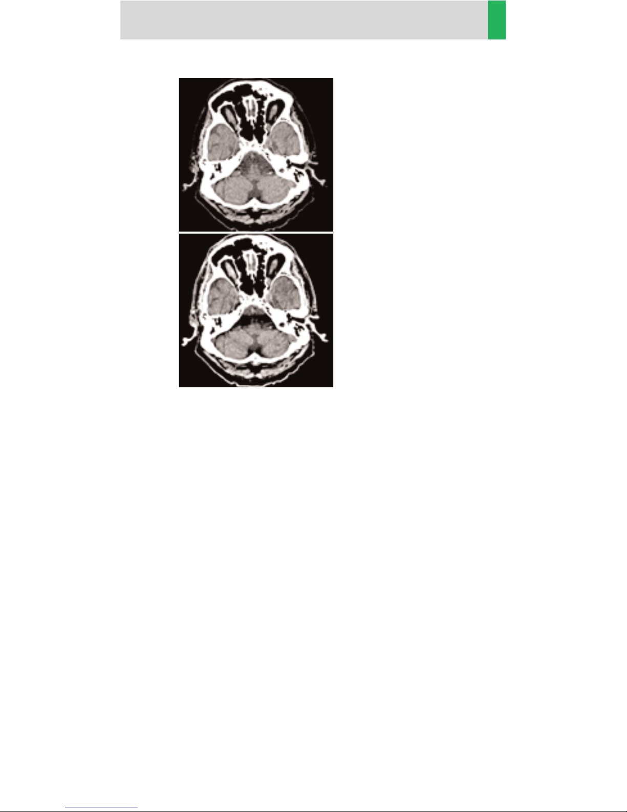
Image Filter
There are 4 different filters available:
PFO: To reduce beam-hardening artifacts in head
images, particularly in the base of the skull, use the
Posterior Fossa Optimization (PFO) filter. It is highly
recommended to use the PFO filter for all soft tissue
reconstruction.
13
General
ASA: The Advanced Smoothing Algorithm (ASA) filter
reduces noise in soft tissue while edges with high contrast are preserved.
LCE: The Low-contrast enhancement (LCE) filter
enhances low-contrast detectability. It reduces the
image noise.
HCE: The High-contrast enhancement (HCE) filter
enhances high-contrast detectability. It increases the
image sharpness.
Reconstruction
with PFO filter.
Reconstruction
without PFO filter.

14
General
Effective mAs
In sequential scanning, the dose (D
seq
) applied to the
patient is the product of the tube current-time (mAs)
and the CTDI
w
per mAs:
D
seq
= D
CTDI
w
x mAs
In spiral scanning, however, the applied dose (D
spiral
)
is influenced by the “classical” mAs (mA x Rot Time) and
in addition by the Pitch Factor. For example, if a Multislice CT scanner is used, the actual dose applied to the
patient in spiral scanning will be decreased when the
Pitch Factor is larger than 1, and increased when the
Pitch Factor is smaller than 1. Therefore, the dose in
spiral scanning has to be corrected by the Pitch Factor:
D
spiral
= (D
CTDI
w
x mA x Rot Time)/Pitch Factor
To make it easier for the users, the concept of the
“effective” mAs was introduced with the SOMATOM
Multislice scanners.
The effective mAs takes into account the influence of
pitch on both the image quality and dose:
Effective mAs = mAs/Pitch Factor
To calculate the dose on the SOMATOM Emotion 6,
you simply have to multiply the CTDI
W
per mAs with
the effective mAs of the scan:
D
spiral
= D
CTDI
w
x effective mAs
For spiral scan protocols, the indicated mAs is the effective mAs per image. The correlation between tube
current mA and effective mAs of spiral scans on a Multislice CT scanner is given by the following formula:
Effective mAs = mA x RotTime/Pitch Factor
Pitch Factor =
Feed/Rot
nrow x Slice collimation
mA =
effective mAs
x Pitch Factor
RotTime
where collimated Slice refers to the collimation of one
detector row, and nrow is the number of used detector
rows.

15
General
Dose Information
CTDIWand CTDI
Vol
The average dose in the scan plane is best described by
the CTDI
W
for the selected scan parameters. The CTDI
W
is measured in the dedicated plastic phantoms – 16 cm
diameter for head and 32 cm diameter for body (as
defined in IEC 60601-2 -44). This dose number gives a
good estimate for the average dose applied in the
scanned volume as long as the patient size is similar to
the size of the respective dose phantoms.
Since the body size can be smaller or larger than
32 cm, the CTDI
W
value displayed can deviate from the
dose in the scanned volume.
The CTDIWdefinition and measurement is based on
single axial scan modes. For clinical scanning, i. e. scanning of entire volumes in patients, the average dose
will also depend on the table feed in between axial scans
or the feed per rotation in spiral scanning. The dose,
expressed as the CTDI
W
, must therefore be corrected by
the pitch-factor of the spiral scan or an axial scan series
to describe the average dose in the scanned volume.
For this purpose the IEC defined the term “CTDI
Vol
“ in
September 2002:
CTDI
Vol
= CTDIW/pitch-factor
This dose number is displayed on the user interface for
the selected scan parameters.
Please note: Up to now the dose display on the
Somaris\5 user interface was labeled “CTDI
W
“.
This displayed CTDI
W
was also corrected for the pitch.

16
The CTDI
Vol
value does not provide the entire information
of the radiation risk associated with CT examination.
For this purpose, the concept of the “Effective Dose“ was
introduced by ICRP (International Commission on
Radiation Protection). The effective dose is expressed
as a weighted sum of the dose applied not only to the
organs in the scanned range, but also to the rest of the
body. It could be measured in whole body phantoms
(Alderson phantom) or simulated with Monte Carlo
techniques.
The calculation of the effective dose is rather complicated and has to be done by sophisticated programs.
These have to take into account the scan parameters,
the system design of individual scanner, such as x-ray
filtration and gantry geometry, the scan range, the
organs involved in the scanned range and the organs
affected by scattered radiation. For each organ, the
respective dose delivered during the CT scanning has
to be calculated and then multiplied by its radiation
risk factor. Finally the weighted organ dose numbers
are added up to get the effective dose.
The concept of effective dose would allow the comparison of radiation risk associated with different CT or
x-ray exams, i. e. different exams associated with the
same effective dose would have the same radiation risk
for the patient. It also allows comparing the applied
x-ray exposure to the natural background radiation,
e. g. 2 – 3 mSv per year in Germany.
General

17
General
CARE Dose
CARE Dose is a clinical application package that provides real-time tube current modulation for Spiral and
Sequential Scanning.
CARE Dose reduces patient dose significantly, especially in the regions of shoulder and pelvis. It decreases
tube load, which extends the capacity for volume scanning with thinner slices, larger volumes or Multi-phase
studies.
It can also improve image quality by increasing mA
thus reducing image noise on the lateral views.
How Does it Work
It reduces the mA for low attenuation views up to 90%
and keeps the nominal higher mA for high attenuation
views, e. g. in the lateral projection (Fig. 4). This is done
“on-the-fly”, i. e. the scanner adapts the mA in real-time,
according to the patient’s attenuation profile (Fig. 5).
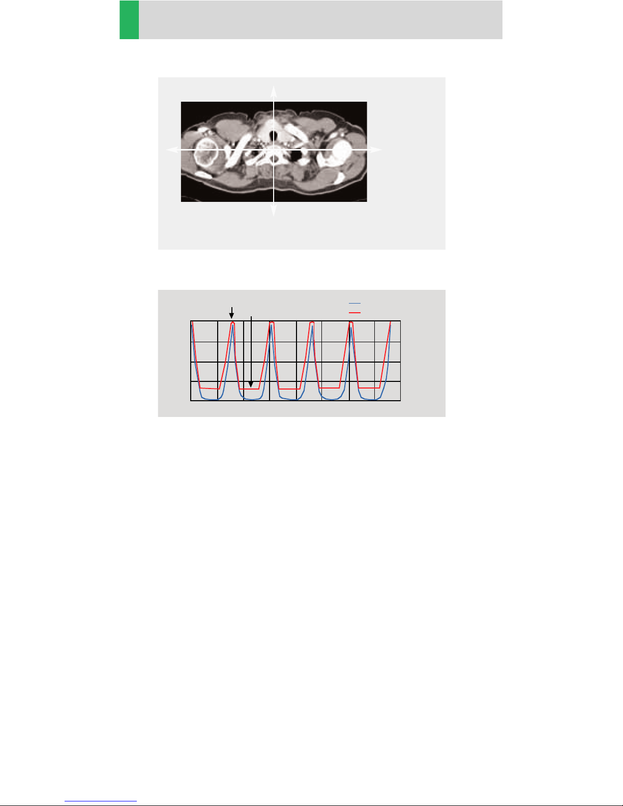
Fig. 4: Example of scanning in the shoulder region.
High
attenuation,
high mA
Low attenuation,
low mA
18
General
Fig. 5: Principle of CARE Dose tube current adaptation.
• CARE Dose is pre-selected by default for most standard
protocols. It can be switched on/off in the scan card.
• For the average patients examination, CARE Dose
does not require any manual changes to the scan
protocol. However, the mAs must be adapted manually for obese and pediatric patients.
• The mean value of the mAs applied will be lower
than what you have selected. Although the average
mA for the entire scan will be lower than selected, we
allow the scanner to apply increased mA levels for
the high attenuation views. This may cause different
results of the tube load controller when switching
on and off CARE Dose.
• The mean value of the effective mAs applied is shown
in the image text.
lateral
1.00
0.75
0.50
0.25
rel. units
a.p.
time
Object attenuation
Modulated tube current

19
General
Workflow
Auto Load in 3D and Postprocessing Presets
You can activate the “Auto load in 3D” function on the
Examination Card/Auto Tasking and link it to a recon
job. For example, the 2
nd
recon job with thinner slice
width in some of the examination protocols. If the postprocessing type is chosen from the pull down menu,
the reconstructed images will be loaded automatically
into the 3D Card on the Navigator with the corresponding postprocessing type.
On the 3D Card you have the possibility to create MPR,
MIPthin Range Parallel and Radial protocols which can
be linked to a special series.
For example, if you always do sagittal Multiplanar
Reconstructions for a Spine examination, you load once
a Spine examination into the 3D Card. Select the image
type (MPR, MIPthin), select the orientation and open
the Range Parallel function. Adapt the range settings
(Image thickness, Distance between the images etc.)
and hit the link button. From that point on, you have a
predefined postprocessing protocol, linked to the series
description of a Spine examination.
Exactly the same can be done for VRT presets. In the
main menu, under Type/VRT Definition, you can link
VRT presets with a series description.

20
General
Some of the Scan protocols, primarily for Angio examinations, are already preset in the protocol with Auto load
in 3D. If you prefer not to use this preset, please deselect the Auto load in 3D and save your scan protocol.
Some of the Scan protocols are preset in the protocol
with links to a postprocessing protocol. If you prefer
not to have this preset, please delete the Range Parallel
preset or overwrite them with your own settings.
Contrast Medium IV Injection*
The administration of a contrast medium depends on
the indication and on the delay times to be used during
the examination. The patient’s weight and circulatory
system condition also play a role. In general, no more
than 3 ml per kg of body weight for adults and 2 ml per
kg of body weight for children should be applied.
As a rule of thumb, the contrast medium injection
should be stopped when the scan (or acquisition)
is finished. Keep this in mind, as you may save contrast
medium on your routine studies since the Multislice
spiral scan can be up to 10 times faster than a 1 second,
single slice spiral scan.
For CTA studies (arterial phase), the principle is to keep
contrast injection for the whole scan. Thus, the total
amount of contrast medium needed should be calculated with the following formula:
CM = (start delay time + scan time) x flow rate.
CARE Bolus or Test Bolus may be used for optimal
contrast bolus timing. Please refer to the Application
Guide for special protocols.
* For more information regarding the general use
of drugs and doses mentioned in this guide, please
refer to page 2.

21
General
How to Create your own
Scan Protocols
User-specific scan protocols can be saved with the
following basic procedure:
• Register a test patient, patient position must be
Head First – Supine
• Select a scan protocol.
• Set the table position to 0 (either at the gantry panel,
or on the topogram routine card).
• Modify the scan protocol, change parameters, add
new ranges etc.
• Do not load the scan protocol.
• Select Edit/Save Scan Protocol in the main menu.
• Select the organ region and the scan protocol name
in the pop-up dialog. You can either use the same
name to modify the existing scan protocol, or enter
a new name, which will create a new protocol name
and will not alter any of the existing protocols already
stored.

22
General
Tips
– We recommend the use of the default scan protocols
in order to achieve adequate image quality for the
“typical” patient. Using the default scan protocols
minimizes the occurrence of tube cooling delays and
maximizes x-ray tube life.
– It is recommended that you save your own scan
protocol with a new name in order to avoid overwriting the default scan protocol.
– You may use preceding numbers (e. g. 1_Abdomen)
for user specific scan protocols to make them appear
on top of the list and to distinguish them from the
Siemens defaults.
– Do not use special characters like ”/”, ”.”, ”\” or ”blank”
within scan protocol names.
– Do not rename scan protocol files on Windows NT
level – this will lead to inconsistencies.
– Do not mix head and body scan protocols: e. g. do
not save a head mode in the abdomen directory.
– System/Run offers the tool “Restore Default Scan
Protocols“ which allows you to remove user specific
scan protocols and to restore the Siemens default
settings.
– System/Edit offers save/delete Scan Protocols.
– System/Run also offers the tool “List Scan Protocols“
which generates an HTML table of all available scan
protocols. This list can be printed or saved on Floppy
(“File/Save As…“).

23
General

24
Children
Overview
This folder contains 24 organ specific pediatric protocols with 2 to 5 age or weight dependant subgroups.
For your convenience, the protocols are numbered
according to the body regions, i. e. from Head to Extremities.
The scan protocols for Head and Neck regions are
defined according to age, and the scan protocols for
the other body regions are defined according to body
weight.
As a default, the effective mAs is set to the lowest
category, e. g. less than 6 months in head modes, and
the suggested effective mAs values for the other categories are written in additional lines in the chronicle.
Whenever possible 80 kV or 110 kV are used instead of
130 kV, either to exploit the significantly higher image
contrast of iodine contrast media at 80 kV or to reach a
lower dose level than possible with 130 kV.
• Head Angio
For head CT Angio studies
• HeadAngio06s
For head CT Angio studies, using a 0.6 sec.
rotation time (optional)
• Head
For routine head spiral studies
• HeadSeq
For routine head sequential studies
• Sinus
For routine sinus spiral studies
• InnerEar
High Resolution mode for inner ear spiral studies
with 6 x 0.5 mm slice collimation (optional)
• NeckRoutine
For routine neck spiral studies
• CarotidCTA
For carotid CT Angio studies
• CarotidCTA06s
For carotid CT Angio studies, using a 0.6 sec.
rotation time (optional)

25
Children
• NeonateBody
Spiral mode for neonate studies
• NeonateBody06s
Spiral mode for neonate studies, using 0.6 sec.
rotation time (optional)
• ThoraxRoutine
For routine chest spiral studies
• ThoraxRoutine06s
For routine chest spiral studies, using 0.6 sec.
rotation time (optional)
• ThoraxCombi
For the combination of thin slice lung and routine
thorax studies
• ThoraxCombi06s
For the combination of thin slice lung and routine
thorax studies, using 0.6 sec. rotation time (optional)
• ThoraxSeqHR
High resolution sequential mode for lung studies
• AbdPelRoutine
For routine abdominal spiral studies
• AbdPelRoutine06s
For routine abdominal spiral studies, using a 0.6 sec.
rotation time (optional)
• AbdCTA
For abdominal CT Angio studies
• AbdCTA06s
For abdominal CT Angio studies, using a 0.6 sec.
rotation time (optional)
• Spine
For routine spine spiral studies
• Spine Sagittal
Thin slice mode for spine spiral studies when
Multi Planar Reformations are necessary
• Extremity
For routine extremity spiral studies
• ExtremityHR
High Resolution mode for extremity spiral studies
with 6 x 0.5 mm slice collimation (optional)

26
Children
Hints in General
1. Topograms: 256 mm lateral topograms are defined
for the head modes, and 512 mm AP topograms are
defined for the body modes. Please keep in mind that
the children’s size can be dramatically different. You
should press the “Hold Measurement“ button whenever the range shown on the real time growing topogram is long enough, in order to avoid unnecessary
radiation.
2. Gantry tilt is available for both, sequence and spiral
scanning. However, image artefacts may occur if spirals
are acquired with a tilt angle greater than 8°.
3. For all head studies, it is very important for image
quality purposes to position the patient in the center of
the scan field. Use the lateral laser beam to make sure
that the patient is positioned in the center.
4. Warm surroundings and dimmed lighting are helpful to make children more cooperative.
5. Sedation: Although the advent of the Multislice CT
scanner has enabled the user to scan through an area
of interest much faster than ever, sometimes, patient
motion can still lead to severe motion artifacts seen on
the resultant images. This becomes a factor especially
with infants and younger children who are unable to
hold still for the exam. Sedating this population may
be a viable option for your institution. Of course, appropriate protocols need to be established at your specific
institution. For instance, the drug of choice for specific
ages/weights of these patients (taking into consideration the total time of the exam), the form of administration, patient preps, adequate monitoring of the
patient (pre-scan, during the exam and post-scan) etc.
should all be taken into consideration.

27
Children
The proper personnel and equipment must also
be readily available in the event of a problem.
6. Oral and rectal contrast administration: Depending
on the reason for the exam/status of the patient, oral
contrast may or may not be given to these patients.
In general, oral contrast is recommended to opacify
the intestinal tract, as unopacified bowel can have
the appearance of abdominal fluid or mass effect. Oral,
as well as rectal contrast may be required. Usually, a
diluted mixture of iodine and water is used as an oral
agent. Different substances can be added to this mixture to help reduce the bitter taste and make it more
pleasing to the child (apple juice, fruit drink mixes are
just a few of these). Barium may of course be used
in some cases as well. Negative contrast agents such
as water are becoming more popular for delineation
of stomach or bowel wall borders, or when 3D reconstructions are needed. The user needs to be aware of
all the contraindications of any of the contrast agents
they are using. It is recommended to refer to the specific vendors recommendations regarding this.
7. I.V. contrast administration: In general, 1 – 2 ml per
kg of body weight should be applied, however, since
the scanning can be completed in just a few seconds,
please keep in mind that the total injection time should
not be longer than the sum of start delay time and the
scan time – do not inject contrast after the scanning is
finished.
It is recommended to use CARE Bolus in order to
achieve optimal contrast enhancement.
Both start delay time and injection rate are exam-/
patient-dependent. I.V. injection with a power injector
is recommended for all scans whenever possible.
Some guidelines to follow with respect to flow rate are
noted in the chart below.

28
Children
Note: these injector guidelines are based on an
antecubital injection site. These guidelines may need
to be adjusted if the site is more peripheral.
Needle Size (gauge) Flow Rate (ml/sec.)
22 1.5
20 2.0 – 3.0
18 3.0 – 5.0
Central lines and ports may need to be hand injected
or power injected at a very low flow rate (1 ml/sec.).
PIC lines and 24 gauge (or smaller) lines are usually
hand injected. All of these protocols should be decided
on by your institution’s appropriate personnel.
8. 80 kV was also used for applications when the
lowest achievable mAs at 110 kV was still higher than
necessary for sufficient noise level (for technical
reasons, generators need to operate at a certain minimum current for stable operation). For applications
such as neonate or airway scanning, the low tube output at 80 kV can be used to further reduce the dose to
the patient.
9. Please observe the recommended mAs settings in
the chronicle.
Note, that these recommendations are valid for the
default tube voltage of the specific protocol.
10. To further optimize MPR image quality we
recommend that you reduce one or more of the following: collimation, reconstruction increment, pitch
factor while using a wider slice width for image reconstruction.

29
Children
Head kernels:
• For head scans of small children, the kernels C20s,
C30s (e. g. for soft tissue studies) and C60s (e. g. for
sinuses) should be chosen instead of the ”adult” head
kernels H20s, H30s and H60s.
• For soft tissue head studies, the standard kernel is
H40s; softer images are obtained with H30s or H20s,
H10s, sharper images with H50s. The kernels H21s,
H31s, H41s yield the same visual sharpness as H20s,
H30s, H40s, but a more agreeable image appearance
and sometimes even better low contrast detectability,
the reason is, as with B31s and B41s, the fine-grained
noise structure.
• For the standard head protocols, we propose H21s,
H31s, H41s.
• High resolution head studies should be performed
with H60s, H70s (e. g. for dental and sinuses) and
H80s, H90s (e. g. inner ear).

30
Children
Body kernels:
• As standard kernels for body tissue studies B30s or
B40s are recommended; softer images are obtained
with B20s or B10s (extremely soft). The kernels B31s
or B41s have about the same visual sharpness as B30s,
respectively, B40s, the image appearance, however,
is more agreeable due to a ”fine-grained” noise structure; quite often, the low contrast detectability is
improved by using B31s, B41s instead of B30s, B40s.
• The 2 kernels B35s and B46s are especially designed
for cardiac application, in particular, B35s should be
used for Ca-scoring, and B46s for patency of stents.
• For higher sharpness, as is required e. g. in patient
protocols for cervical spine, shoulder, extremities,
thorax, the kernels B50s, B60s, B70s, B80s are available.
• A special high resolution lung kernel is supplied with
B90s; by using kernel B90s, practically the same
image impression is obtained as with HCE-filtering of
a B40s image.
 Loading...