

Siemens Solkor 7PG2113, Solkor 7PG2116, Solkor 7PG2114, Solkor 7PG2115 Technical Manual
7PG2113/4/5/6 Solkor
Feeder Protection
Answers for energy
Reyrolle
Protection
Devices

Contents
Technical Manual Chapters
1. Description of Operation
2. Settings
3. Performance Specification
4. Communications
5. Installation
6. Commissioning and Maintenance
7. Applications Guide
7PG2113/4/5/6 Solkor Contents
The copyright and other intellectual property rights in this document, and in any model or article produced from it
(and including any registered or unregistered design rights) are the property of Siemens Protection Devices
Limited. No part of this document shall be reproduced or modified or stored in another form, in any data retrieval
system, without the permission of Siemens Protection Devices Limited, nor shall any model or article be
reproduced from this document unless Siemens Protection Devices Limited consent.
While the information and guidance given in this document is believed to be correct, no liability shall be accepted
for any loss or damage caused by any error or omission, whether such error or omission is the result of
negligence or any other cause. Any and all such liability is disclaimed.
©2010 Siemens Protection Devices Limited

7PG2113/4/5/6 Solkor Description of Operation
7PG2113/4/5/6
Feeder Protection
Document Release History
This document is issue 2010/08. The list of revisions up to and including this issue is:
2010/08 First Issue
Software Revision History
2009/04 2436H80003R1g-1c 7PG2113/5
2436H80004R1g-1c 7PG2114/6
First Release
The copyright and other intellectual property rights in this document, and in any model or article produced from it
(and including any registered or unregistered design rights) are the property of Siemens Protection Devices
Limited. No part of this document shall be reproduced or modified or stored in another form, in any data retrieval
system, without the permission of Siemens Protection Devices Limited, nor shall any model or article be
reproduced from this document unless Siemens Protection Devices Limited consent.
While the information and guidance given in this document is believed to be correct, no liability shall be accepted
for any loss or damage caused by any error or omission, whether such error or omission is the result of
negligence or any other cause. Any and all such liability is disclaimed.
©2010 Siemens Protection Devices Limited

7PG2113/4/5/6 Solkor Description of Operation
Contents
Section 1: Introduction ............................................................................................................................................. 6
1.1 General Safety Precautions .................................................................................................................... 6
1.1.1 Current Transformer Circuits..................................................................................................... 6
1.1.2 External Resistors..................................................................................................................... 6
1.1.3 Front Cover ............................................................................................................................... 6
Section 2: Hardware Description............................................................................................................................ 15
2.1 General ................................................................................................................................................. 15
2.2 Case...................................................................................................................................................... 16
2.3 Front Cover ........................................................................................................................................... 17
2.4 Power Supply Unit (PSU)...................................................................................................................... 17
2.5 Operator Interface/ Fascia .................................................................................................................... 17
2.6 Current Inputs ....................................................................................................................................... 21
2.7 Voltage Inputs ....................................................................................................................................... 21
2.8 Binary Inputs ......................................................................................................................................... 22
2.9 Binary Outputs (Output Relays) ............................................................................................................ 22
2.10 Virtual Input/Outputs ............................................................................................................................. 24
2.11 Self Monitoring ...................................................................................................................................... 24
2.11.1 Protection Healthy/Defective................................................................................................... 24
Section 3: Current Differential Protection Function ................................................................................................ 25
3.1 Description ............................................................................................................................................ 25
3.2 Operation .............................................................................................................................................. 27
3.3 Theory of Summation Transformer ....................................................................................................... 34
Section 4: Numeric Protection Module Functions .................................................................................................. 35
4.1 Current Protection: Phase Overcurrent (67, 51, 50).............................................................................. 35
4.1.1 Directional Control of Overcurrent Protection (67) – 7PG2114/6 ............................................ 35
4.1.2 Instantaneous Overcurrent Protection (50) ............................................................................. 37
4.1.3 Time Delayed Overcurrent Protection (51).............................................................................. 38
4.1.4 Current Protection: Voltage Controlled Overcurrent (51V) – 7PG2114/6 ................................ 40
4.2 Current Protection: Derived Earth Fault (67N, 51N, 50N) ..................................................................... 41
4.2.1 Directional Control of Derived Earth Fault Protection (67N) – 7PG2114/6.............................. 41
4.2.2 Instantaneous Derived Earth Fault Protection (50N)............................................................... 42
4.2.3 Time Delayed Derived Earth Fault Protection (51N) ............................................................... 43
4.3 Current Protection: Measured Earth Fault (67G, 51G, 50G) ................................................................. 45
4.3.1 Directional Control of Measured Earth Fault Protection (67G) – 7PG2114/6 .......................... 45
4.3.2 Instantaneous Measured Earth Fault Protection (50G) ........................................................... 46
4.3.3 Time Delayed Measured Earth Fault Protection (51G) ........................................................... 47
4.4 Current Protection: High Impedance Restricted Earth Fault - (64H) ..................................................... 49
4.5 Current Protection: Cold Load (51c) ..................................................................................................... 50
4.6 Current Protection: Negative Phase Sequence Overcurrent - (46NPS) ................................................ 51
4.7 Current Protection: Under-Current (37)................................................................................................. 52
4.7.1 Current Protection: Thermal Overload (49) ............................................................................. 53
4.8 Voltage Protection: Phase Under/Over Voltage (27/59) – 7PG2114/6.................................................. 55
4.9 Voltage Protection: Negative Phase Sequence Overvoltage (47) – 7PG2114/6 ................................... 56
4.10 Voltage Protection: Neutral Overvoltage (59N) – 7PG2114/6 ............................................................... 57
Section 5: Control & Logic Functions ..................................................................................................................... 58
5.1 Auto-Reclose (79) Optional Function .................................................................................................... 58
5.1.1 Overview ................................................................................................................................. 58
5.1.2 Auto Reclose sequences ........................................................................................................ 60
5.1.3 Autoreclose Prot’n Menu......................................................................................................... 61
5.1.4 Autoreclose Config Menu........................................................................................................ 61
5.1.5 P/F Shots sub-menu ............................................................................................................... 63
5.1.6 E/F Shots sub-menu ............................................................................................................... 63
5.1.7 SEF Shots sub-menu.............................................................................................................. 63
5.1.8 Extern Shots sub-menu........................................................................................................... 64
©2010 Siemens Protection Devices Limited Chapter 1 Page 2 of 80

7PG2113/4/5/6 Solkor Description of Operation
5.2 Manual Close ........................................................................................................................................ 66
5.3 Circuit Breaker (CB) .............................................................................................................................. 66
5.4 Quick Logic ........................................................................................................................................... 68
Section 6: Supervision Functions........................................................................................................................... 70
6.1 Circuit Breaker Failure (50BF) .............................................................................................................. 70
6.2 VT Supervision (60VTS) – 7PG2114/6 ................................................................................................. 71
6.3 CT Supervision (60CTS) ....................................................................................................................... 73
6.3.1 60CTS – 7PG2113/5............................................................................................................... 73
6.3.2 60CTS – 7PG2114/6............................................................................................................... 73
6.4 Broken Conductor (46BC)..................................................................................................................... 74
6.5 Trip/ Close Circuit Supervision (74TCS & 74CCS) ............................................................................... 75
6.6 2nd Harmonic Block/Inrush Restraint (81HBL2) phase elements only.................................................. 76
6.7 Demand ................................................................................................................................................ 76
Section 7: Other Features...................................................................................................................................... 77
7.1 Data Communications........................................................................................................................... 77
7.2 CB Maintenance ................................................................................................................................... 77
7.2.1 Output Matrix Test .................................................................................................................. 77
7.2.2 CB Counters ........................................................................................................................... 77
7.2.3 I2t CB Wear ............................................................................................................................. 77
7.3 Data Storage......................................................................................................................................... 78
7.3.1 General ................................................................................................................................... 78
7.3.2 Event Records ........................................................................................................................ 78
7.3.3 Waveform Records. ................................................................................................................ 78
7.3.4 Fault Records.......................................................................................................................... 78
7.4 Metering ................................................................................................................................................ 79
7.5 Operating Mode .................................................................................................................................... 79
7.6 Control Mode ........................................................................................................................................ 79
7.7 Real Time Clock.................................................................................................................................... 80
7.7.1 Time Synchronisation – Data Communication Interface ......................................................... 80
7.7.2 Time Synchronisation – Binary Input ...................................................................................... 80
7.8 Settings Groups .................................................................................................................................... 80
7.9 Password Feature................................................................................................................................. 80
©2010 Siemens Protection Devices Limited Chapter 1 Page 3 of 80

7PG2113/4/5/6 Solkor Description of Operation
List of Figures
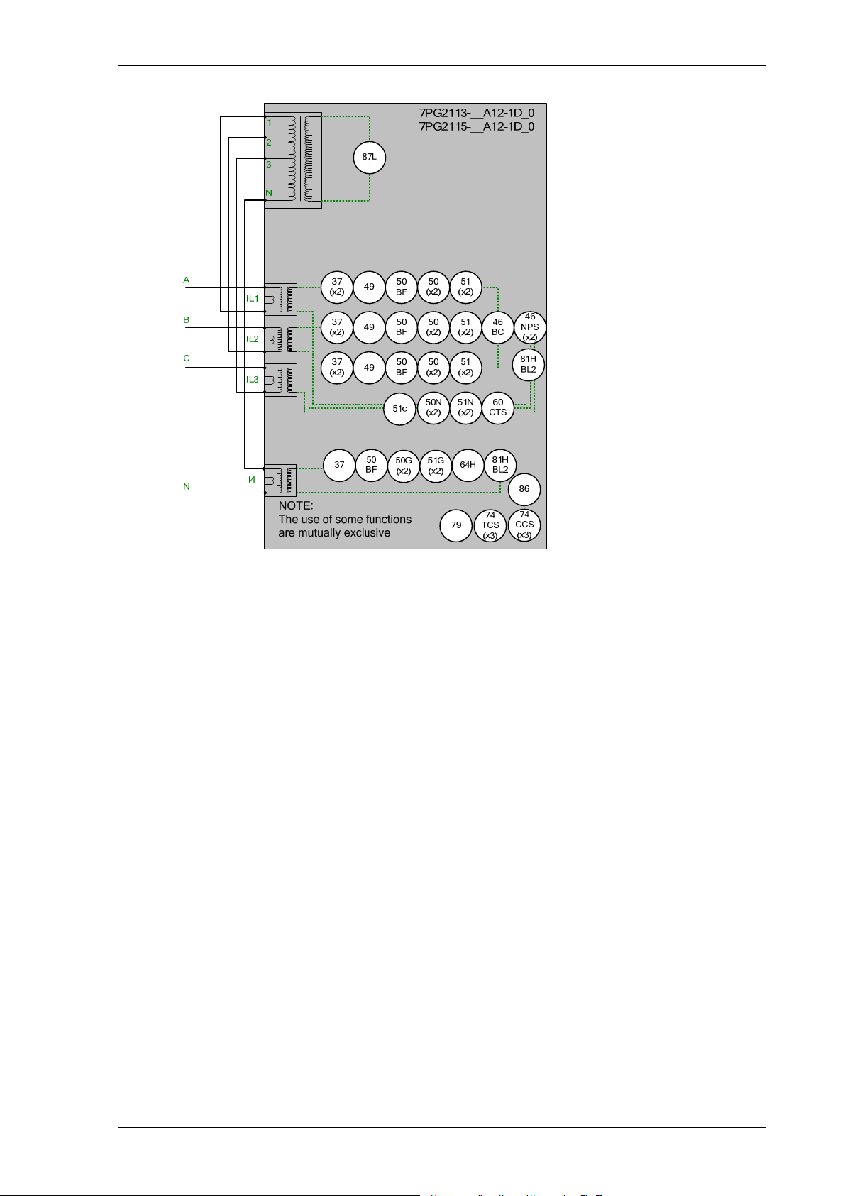
Figure 1.1-1 Functional Diagram of 7PG2113/5 Relay with Autoreclose ................................................................. 8
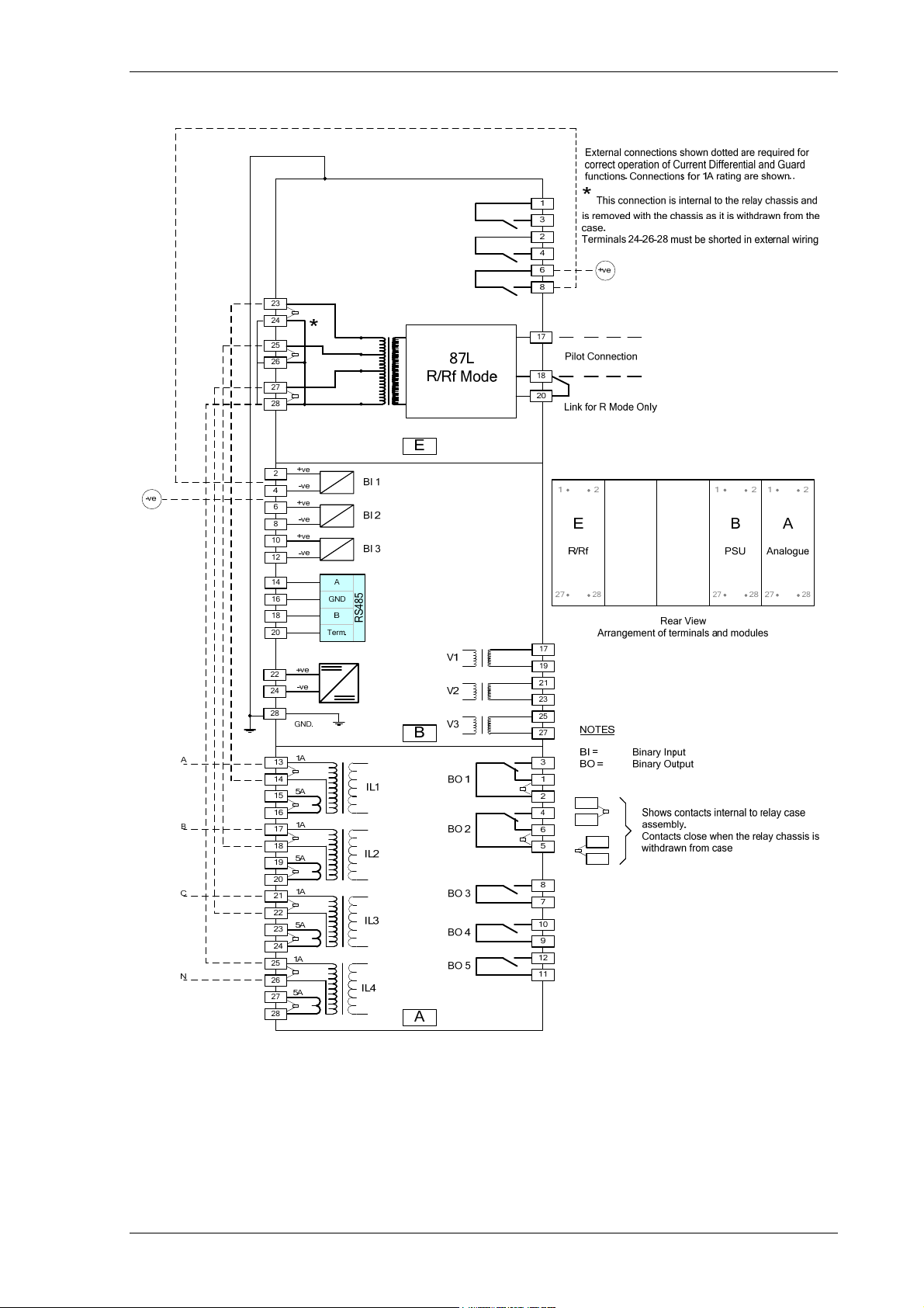
Figure 1.1-2 Connections Diagram for 7PG2113 Relay ........................................................................................... 9
Figure 1.1-3 Connections Diagram for 7PG2115 Relay ......................................................................................... 10
Figure 1.1-4 Functional Diagram of 7PG2114/6 Relay with Autoreclose ............................................................... 12
Figure 1.1-5 Connections Diagram for 7PG2114 Relay ......................................................................................... 13
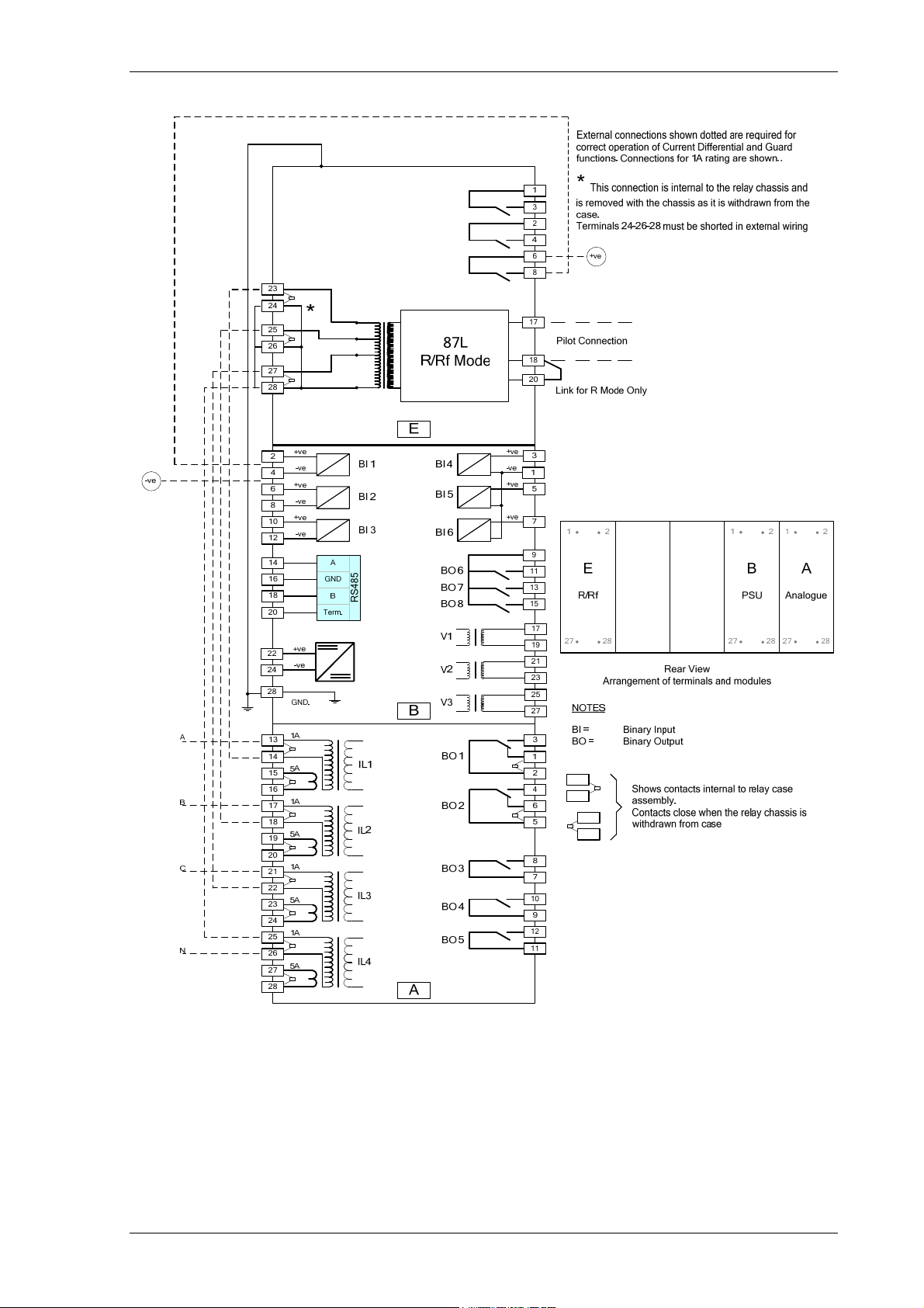
Figure 1.1-6 Connections Diagram for 7PG2116 Relay ......................................................................................... 14
Figure 2.2-1 Relay shown withdrawn ..................................................................................................................... 16
Figure 2.2-2 Rear view of 7PG2113/4/5/6 Relay................................................................................................... 16
Figure 2.2-3 Earth Symbol ..................................................................................................................................... 16
Figure 2.3-1 Relay with standard transparent cover .............................................................................................. 17
Figure 2.5-1 Relay with Transparent cover removed ............................................................................................. 17
Figure 2.5-2 Close up of typical relay labels .......................................................................................................... 18
Figure 2.5-3 Close up of Relay Identifier................................................................................................................ 19
Figure 2.5-4 LED Indication Label.......................................................................................................................... 21
Figure 2.8-1 Binary Input Logic .............................................................................................................................. 22
Figure 2.9-1 Binary Output Logic ........................................................................................................................... 23
Figure 3.1-1 Solkor Rf schematic........................................................................................................................... 25
Figure 3.1-2 Solkor R schematic............................................................................................................................ 25
Figure 3.1-3 Solkor Rf 15kV schematic.................................................................................................................. 26
Figure 3.2-1 Through Fault, zero ohm pilots, Positive half cycle............................................................................ 28
Figure 3.2-2 Through Fault, zero ohm pilots, Negative half cycle. ......................................................................... 28
Figure 3.2-3 Through Fault, 1000 ohm pilots, Positive half cycle........................................................................... 29
Figure 3.2-4 Through Fault, 1000 ohm pilots, Negative half cycle. ........................................................................ 29
Figure 3.2-5 Through fault Rf mode, positive half cycle ......................................................................................... 30
Figure 3.2-6 Through fault Rf mode, negative half cycle........................................................................................ 30
Figure 3.2-7 Through fault Rf mode, positive half cycle ......................................................................................... 31
Figure 3.2-8 Through fault Rf mode, negative half cycle........................................................................................ 31
Figure 3.2-9 Internal fault Rf mode, positive half cycle .......................................................................................... 32
Figure 3.2-10 Internal fault Rf mode, negative half cycle ....................................................................................... 32
Figure 3.2-11 Single End Fed fault Rf mode, positive half cycle ............................................................................ 33
Figure 3.2-12 Single End Fed fault Rf mode, negative half cycle .......................................................................... 33
Figure 4.1-1 Logic Diagram: Directional Overcurrent Element (67) ....................................................................... 36
Figure 4.1-2 Logic Diagram: Instantaneous Over-current Element ........................................................................ 37
Figure 4.1-3 Logic Diagram: Time Delayed Overcurrent Element.......................................................................... 39
Figure 4.1-4 Logic Diagram: Voltage Controlled Overcurrent Protection ............................................................... 40
Figure 4.2-1 Logic Diagram: Derived Directional Earth Fault Element ................................................................... 42
Figure 4.2-2 Logic Diagram: Derived Instantaneous Earth Fault Element ............................................................. 43
Figure 4.2-3 Logic Diagram: Derived Time Delayed Earth Fault Protection........................................................... 44
Figure 4.3-1 Logic Diagram: Measured Directional Earth Fault Protection ............................................................ 45
Figure 4.3-2 Logic Diagram: Measured Instantaneous Earth-fault Element........................................................... 46
Figure 4.3-3 Logic Diagram: Measured Time Delayed Earth Fault Element (51G)................................................ 48
Figure 4.4-1 Logic Diagram: High Impedance REF (64H) ..................................................................................... 49
Figure 4.5-1 Logic Diagram: Cold Load Settings (51c) .......................................................................................... 50
Figure 4.6-1 Logic Diagram: Negative Phase Sequence Overcurrent (46NPS)..................................................... 51
Figure 4.7-1 Logic Diagram: Relays with 4 Current Inputs Undercurrent Detector (37) ......................................... 52
Figure 4.7-2 Logic Diagram: Relays with 1 Current Inputs Undercurrent Detector (37) ......................................... 52
Figure 4.7-3 Logic Diagram: Thermal Overload Protection (49S) .......................................................................... 54
Figure 4.8-1 Logic Diagram: Under/Over Voltage Elements (27/59) ...................................................................... 55
Figure 4.9-1 Logic Diagram: NPS Overvoltage Protection (47).............................................................................. 56
Figure 4.10-1 Logic Diagram: Neutral Overvoltage Element (59N)........................................................................ 57
©2010 Siemens Protection Devices Limited Chapter 1 Page 4 of 80

7PG2113/4/5/6 Solkor Description of Operation
Figure 5.1-1 Typical AR Sequence with 3 Inst and 1 Delayed trip ......................................................................... 60
Figure 5.1-2 Basic Auto-Reclose Sequence Diagram ............................................................................................ 65
Figure 5.3-1 Logic Diagram: Circuit Breaker Status............................................................................................... 67
Figure 5.4-1 Sequence Diagram: Quick Logic PU/DO Timers (Counter Reset Mode Off) ..................................... 69
Figure 6.1-1 Logic Diagram: Circuit Breaker Fail Protection (50BF) ...................................................................... 70
Figure 6.2-1 Logic Diagram: VT Supervision Function (60VTS) ............................................................................ 72
Figure 6.3-1 Logic Diagram: CT Supervision Function (60CTS) – 7PG2113/5...................................................... 73
Figure 6.3-2 Logic Diagram: CT Supervision Function (60CTS) – 7PG2114/6...................................................... 74
Figure 6.4-1 Logic Diagram: Broken Conductor Function (46BC) .......................................................................... 74
Figure 6.5-1 Logic Diagram: Trip Circuit Supervision Feature (74TCS) ................................................................. 75
Figure 6.5-2 Logic Diagram: Close Circuit Supervision Feature (74CCS) ............................................................. 75
Figure 6.6-1 Functional Diagram for Harmonic Block Feature (81HBL2) ............................................................... 76
List of Tables
Table 1-1 7PG2113/5 Ordering Options .................................................................................................................. 7
Table 1-2 7PG2114/6 Ordering Options ................................................................................................................ 11
Table 1-3 Summary of Compact Relay Configurations .......................................................................................... 15
Table 3-1 Summation Transformer Output ............................................................................................................ 34
Table 7-1 CB Counters .......................................................................................................................................... 77
Table 7-2 Operating Modes ................................................................................................................................... 79
Symbols and Nomenclature
The following notational and formatting conventions are used within the remainder of this document:
• Setting Menu Location MAIN MENU>SUB-MENU
• Setting: Elem name -Setting
• Setting value: value
• Alternatives: [1st] [2nd] [3rd]
©2010 Siemens Protection Devices Limited Chapter 1 Page 5 of 80
7PG2113/4/5/6 Solkor Description of Operation
Section 1: Introduction
This manual is applicable to the following relays:
• 7PG2113/5 Pilot Wire Differential Relay with Overcurrent and Earth Fault Relay
• 7PG2114/6 Pilot Wire Differential Relay with Directional Overcurrent and Directional Earth Fault Relay
The ‘Ordering Option’ Tables summarise the features available in each model
1.1 General Safety Precautions
1.1.1 Current Transformer Circuits
The secondary circuit of a live CT must not be open circuited. Non-observance of this precaution can
!
result in injury to personnel or damage to equipment.
1.1.2 External Resistors
Where external resistors are connected to the relay circuitry, these may present a danger of electric
shock or burns, if touched.
!
1.1.3 Front Cover
The front cover provides additional securing of the relay element within the case. The relay cover
!
should be in place during normal operating conditions.
©2010 Siemens Protection Devices Limited Chapter 1 Page 6 of 80
7PG2113/4/5/6 Solkor Description of Operation
y
|||||||||||
|||||||||||
y Typ
|||||||||
|
|||||||||
|
,
|||||||||
3
|||||
|C|
|
5
|||||||||
g
|||||||
|
|||||||
|
|||||||
|
y
|||||||
p
A
|||||
|
|||||
|||||
|||
|
p
|||
|||
g
|
|
A
|
|
|
|
|
|
|
|
|
A
|
p
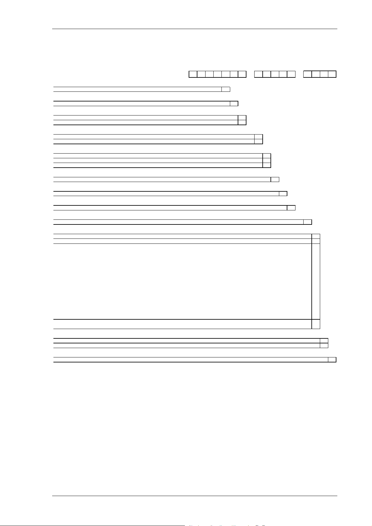
Table 1-1 7PG2113/5 Ordering Options
ORDER-No.: 7PG 211 - A12 -1 0
Protection Product Famil
Solkor R/Rf Scheme
Rela
e
Solkor R/Rf
I/O and Fascia
Case
Non Directional OC, E10 case, 4 CT, 3 Binary Inputs / 5 Binary Outputs, 10 LEDs
Non Directional OC, E10 case, 4 CT, 6 Binary Inputs / 8 Binary Outputs, 10 LEDs
Measurin
1A, 50/60Hz
5A, 50/60Hz
Auxiliar
80-250V DC, binary input threshold 19V DC
80-250V DC, binary input threshold 88V DC
24-60V DC, binary input threshold 19V DC
S
Communica tion Interface
Standard version - included in all models, USB front port, RS485 rear port
Protocol
IEC 60870-5-103, Modbus RTU and DNP3(user selectable setting)
S
Protection Function Packa
For future development
For future development
Standard version - included in all models
37 Undercurrent
46BC Broken conductor/load unbalance
46NPS Negative phase sequence overcurrent
49 Thermal overload
50BF Circuit breaker fail
50G/50N Instantaneous earth fault
50 Instantaneous phase fault overcurrent
51 Time delayed phase fault overcurrent
51G/51N Time delayed earth fault
60CTS CT Supervision
64H High impedance REF
74TCS Trip circuit supervision
51c Cold load pickup
81HBL 2 Inrush Res train t
Standard version - plus
79 Autoreclose
Solkor Mode
Solkor Rf
Solkor R
S
1)
input
voltage
are
are
es
Programmable logic
1)
are
Defaul t mode when supplied, rela y mode is easil y changed la ter m y internal link s
1234567 89101112 13141516
||| ||||| ||||
5
1
|| ||||| ||||
6
1
| ||||| ||||
7
||||| ||||
8
1
2
|||| ||||
9
G
||| ||||
H
||| ||||
J
||| ||||
||| ||||
10
|| ||||
|| ||||
11
1
| ||||
12
||||
2
||||
13
1
|||
14
||
B
C
||
||
||
||
||
||
||
||
||
||
||
||
||
||
||
D
||
15
|
B
|
16
0
©2010 Siemens Protection Devices Limited Chapter 1 Page 7 of 80
7PG2113/4/5/6 Solkor Description of Operation
Figure 1.1-1 Functional Diagram of 7PG2113/5 Relay with Autoreclose
©2010 Siemens Protection Devices Limited Chapter 1 Page 8 of 80
7PG2113/4/5/6 Solkor Description of Operation
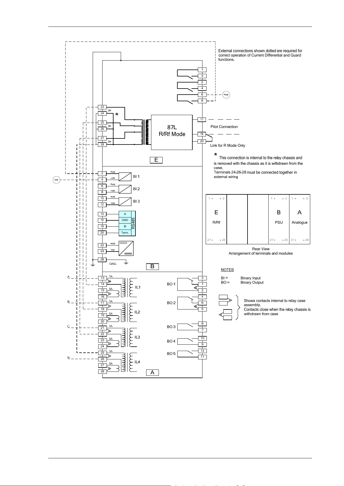
Figure 1.1-2 Connections Diagram for 7PG2113 Relay
©2010 Siemens Protection Devices Limited Chapter 1 Page 9 of 80
7PG2113/4/5/6 Solkor Description of Operation
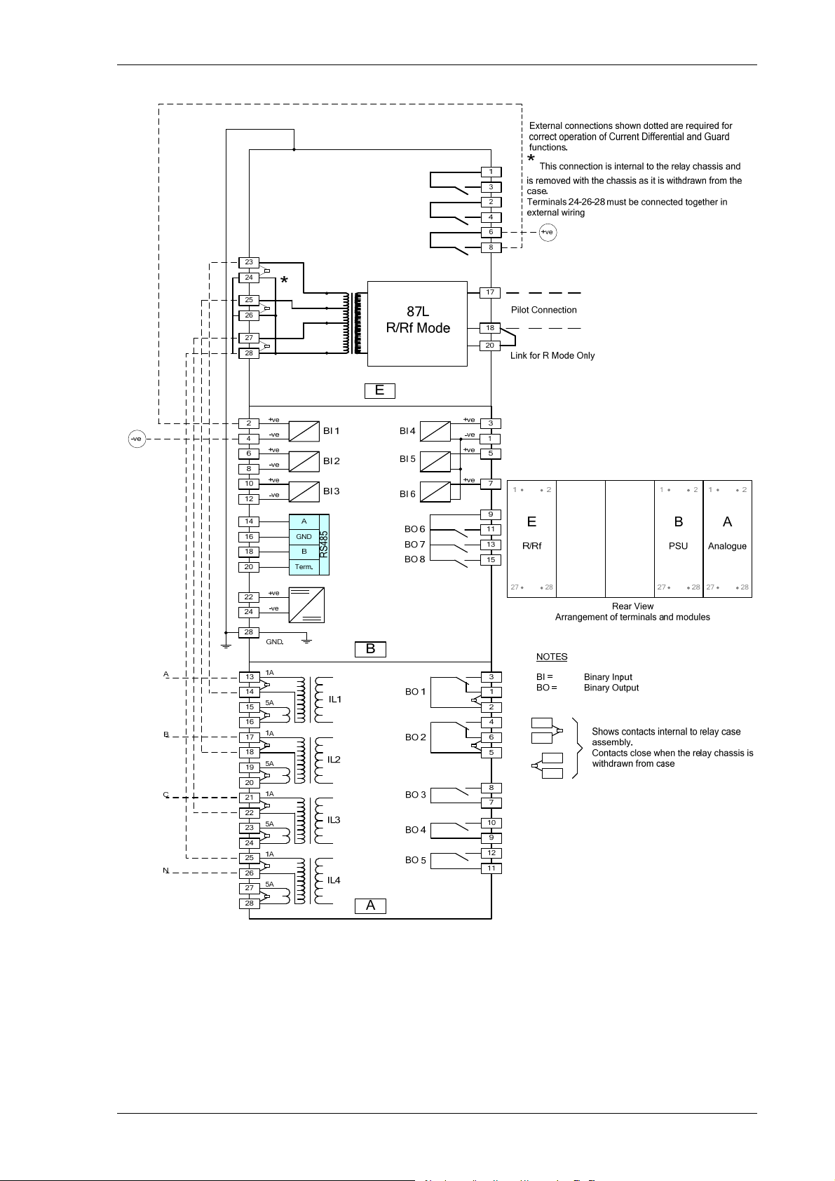
Figure 1.1-3 Connections Diagram for 7PG2115 Relay
©2010 Siemens Protection Devices Limited Chapter 1 Page 10 of 80
7PG2113/4/5/6 Solkor Description of Operation
y
|||||||||||
|||||||||||
y Ty
|||||||||
|
|||||||||
|||||
|C|
|
|||||||||
g
|||||||
|
|||||||
|
y
||||||A
|||||
|||
|
|||
|
|||
g
|
|
A
|
|
|
|
|
|
|
|
|
A
|
|
Table 1-2 7PG2114/6 Ordering Options
ORDER-No.: 7 P G 2 1 1 - A 1 2 - 1 0
Protection Product Famil
Solkor R/Rf Scheme 1
Rela
pe
Solkor R/Rf
Case, I/O and Fascia
Directional OC, E10 case, 4 CT, 3 VT, 3 Binary Inputs / 5 Binary Outputs, 10 LEDs
Directional OC, E10 case, 4 CT, 3VT, 6 Binary Inputs / 8 Binary Outputs, 10 LEDs
Measurin
1A, 50/60Hz 1
5A, 50/60Hz
Auxiliar
80-250V DC, binary input threshold 19 V DC
80-250V DC, binary input threshold 88 V DC
24-60V DC, binary input threshold 19V DC
input
voltage
Spare
Communication Interface
Standard version - included in all models, USB front port, RS485 rear port
Protocol
IEC 60870-5-103, Modbus RTU and DNP3(user selectable setting) 2
Spare
Protection Function Packa
For future development
For future development B
Standard version - included in all models
27/59 Under/Over Voltage
37 Undercurrent
46BC Broken conductor/load unbalance
46NPS Negative phase sequence overcurrent
47 Negative phase sequence voltage
49 Thermal overload
50BF Circuit breaker fail
51V Voltage Controlled Overcurrent
59N Neutral voltage displacement
60CTS CT Supervision
60VTS VT Supervision
64H High impedance REF
67/50 Directional instantaneous phase fault overcurrent
67/50G 67/50N Directional instantaneous earth fault
67/51 Directional time delayed phase fault overcurrent
67/51G 67/51N Directional time delayed earth fault
74TCS Trip circuit supervision
51c Cold load pickup
81HBL2 Inrush Restraint
Standard version - plus
79 Autoreclose
Solkor Mode
Solkor Rf
Solkor R B
Programmable logic
1)
es
Spare
1)
Default mode when supplied, relay mode is easily changed later by internal links
1234567 89101112 13141516
||| ||||| ||||
5
|| ||||| ||||
6
| ||||| ||||
1
| ||||| ||||
7
4
6
||||| ||||
8
|||| ||||
2
|||| ||||
9
||| ||||
G
||| ||||
H
||| ||||
J
||| ||||
||| ||||
10
|| ||||
|| ||||
11
| ||||
1
| ||||
12
||||
13
|||
1
|||
14
C
D
||
||
||
||
||
||
||
||
||
||
||
||
||
||
||
||
||
||
||
||
||
||
15
|
16
0
©2010 Siemens Protection Devices Limited Chapter 1 Page 11 of 80
7PG2113/4/5/6 Solkor Description of Operation
1
2
3
N
A
IL1
IL1
B
IL2
IL2
C
IL3
IL3
N
I4
VL1
VL2
VL3
37
(x2)
37
(x2)
37
(x2)
37
(x4)
(x4)
(x4)
87L
50
49
49
49
50
BF
27
59
27
59
27
59
51V
BF
50
51V
BF
50
51V
BF
51c
81H
64H
BL2
59N
47
(x2)
NOTE:
The use of some functions
are mutually exclusive
7PG2114-__A12-1D_0
7PG2116-__A12-1D_0
67/
67/
50
51
(x4)
(x4)
67/
67/
51
(x4)
67/
51
(x4)
67/
51N
(x4)
67/
51G
(x4)
79
46
BC
60
CTS60VTS
74
TCS
(x3)
50
(x4)
67/
50
(x4)
67/
50N
(x4)
67/
50G
(x4)
46
NPS
(x2)
81H
BL2
CCS
86
74
(x3)
Figure 1.1-4 Functional Diagram of 7PG2114/6 Relay with Autoreclose
©2010 Siemens Protection Devices Limited Chapter 1 Page 12 of 80
7PG2113/4/5/6 Solkor Description of Operation
Figure 1.1-5 Connections Diagram for 7PG2114 Relay
©2010 Siemens Protection Devices Limited Chapter 1 Page 13 of 80
7PG2113/4/5/6 Solkor Description of Operation
Figure 1.1-6 Connections Diagram for 7PG2116 Relay
©2010 Siemens Protection Devices Limited Chapter 1 Page 14 of 80

7PG2113/4/5/6 Solkor Description of Operation
Section 2: Hardware Description
2.1 General
The relay combines the Current Differential function of a Solkor R/Rf relay with the functions and flexibility of a
modern numeric protection device.
Solkor R & Rf are well established Pilot Wire Current Differential Protection for use with privately owned 2 core
pilots with relatively high core resistance.
Solkor R/Rf protection benefits from the following main features:
• High transient stability
• High speed operation (<60ms)
• Little or no variation of settings with pilot length
• Up to 20% of rated load can be tapped off from inside of the protection zone.
• Easy to install, commission and maintain
• 15kV pilot isolation option
• Easily reconnected as either Solkor Rf or Solkor R
• Pilot wire supervision schemes available
• Remote end injection intertripping via pilot cores available
The structure of the numeric guard module is based upon the Reyrolle Compact hardware platform. The
combined relay is supplied in a size E10 case (where 1 x E = width of approx. 26mm). The hardware design
provides commonality between products and components across the Reyrolle Compact range of relays.
Table 1-3 Summary of Compact Relay Configurations
Relay
7PG2113 4 0 3 5 3 10
7PG2115 4 0 6 8 3 10
7PG2114 4 3 3 5 3 10
7PG2116 4 3 6 8 3 10
Numeric modules are assembled from the following printed circuit boards:
1) Front Fascia with 9 configurable LEDs and 1 Relay Healthy LED.
2) Processor module.
3) Current Analogue / Output module
4 x Current + 5 x Binary Outputs (BO)
4) Voltage Analogue / Input / output module
3 x Voltage (7PG2114)
3 x Voltage + 3 x Binary Input and 3 x Binary Output Module. (7PG2116)
5) Power Supply and 3 x Binary Input (BI) and RS485.
Current
Inputs
Voltage
Inputs
Binary
Inputs
Programmable
Binary Outputs
Fixed 87L
Binary outputs
LEDs
©2010 Siemens Protection Devices Limited Chapter 1 Page 15 of 80
7PG2113/4/5/6 Solkor Description of Operation
2.2 Case
The relays are housed in cases designed to fit directly into standard panel racks. The case has a width of 260mm
and a height of 177 mm (4U). The required panel depth (with wiring clearance) is 242 mm.
The relay modules are withdrawable from the front of the case. Contacts in the case ensure that the CT circuits
and normally closed contacts remain short-circuited when the relay is removed. To withdraw the relay modules
remove the front cover by rotating the six securing pins and withdraw using the module handles. The relay
modules should not be carried using these handles..
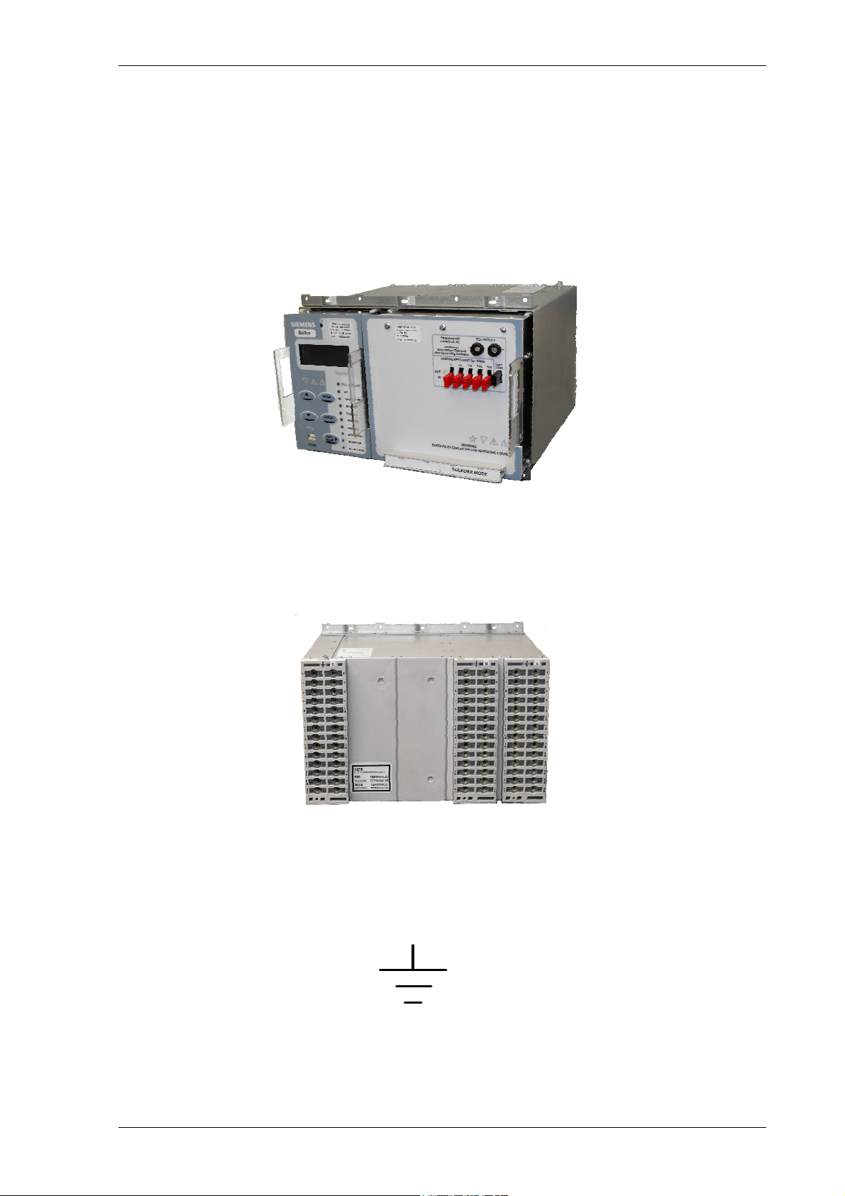
Figure 2.2-1 Relay shown withdrawn
The rear terminal blocks comprise M4 female terminals for wire connections. Each terminal can accept two 4mm
crimps.
Figure 2.2-2 Rear view of 7PG2113/4/5/6 Relay
Located at the top rear of the case is a screw clamp earthing point, this must be connected to terminal B28 and
directly to the main panel earth. This connection point is indicated by the following symbol.
Figure 2.2-3 Earth Symbol
©2010 Siemens Protection Devices Limited Chapter 1 Page 16 of 80
7PG2113/4/5/6 Solkor Description of Operation
2.3 Front Cover
As standard the relay is supplied with a transparent front cover. The front cover is used to secure the relay
modules in the case.
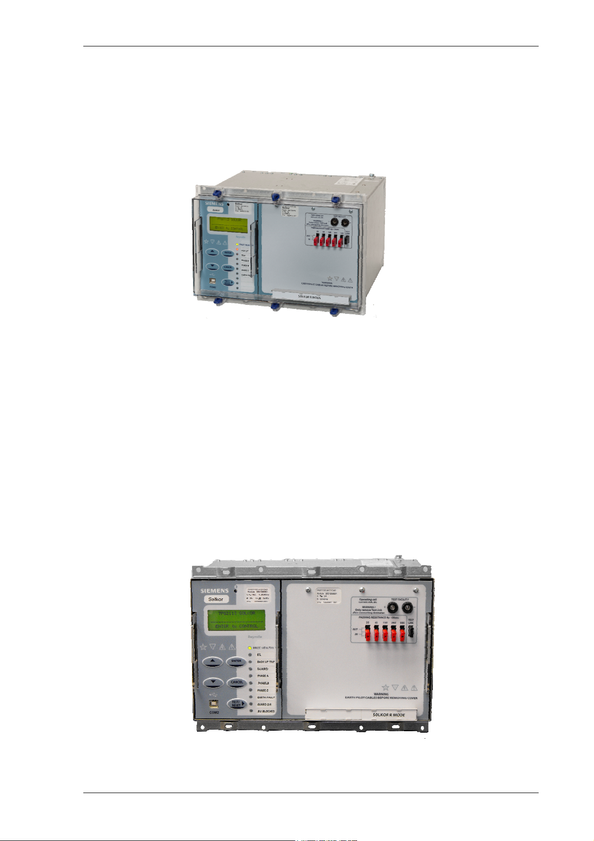
Figure 2.3-1 Relay with standard transparent cover
2.4 Power Supply Unit (PSU)
The relay can be ordered with two different nominal power supply ranges, 24V to 60V and 80V to 320V dc. The
Solkor R/Rf module does not require an auxiliary supply and is universal for all DC ratings.
In the event of the supply voltage level falling below the relay minimum operate level the PSU will automatically
switch itself off and latch out – this prevents any PSU overload conditions occurring. The PSU is reset by
switching the auxiliary supply off and on.
2.5 Operator Interface/ Fascia
The operator interface is designed to provide a user-friendly method of controlling, entering settings and retrieving
data from the relay. Links are provided to allow setting of pilot padding resistance and test points are provided to
allow operating spill current to be measured.
Figure 2.5-1 Relay with Transparent cover removed
©2010 Siemens Protection Devices Limited Chapter 1 Page 17 of 80
7PG2113/4/5/6 Solkor Description of Operation
The fascia is an integral part of the relay modules. Handles are located on the modules which allow them to be
withdrawn from the relay case. The relay should not be carried by these handles.
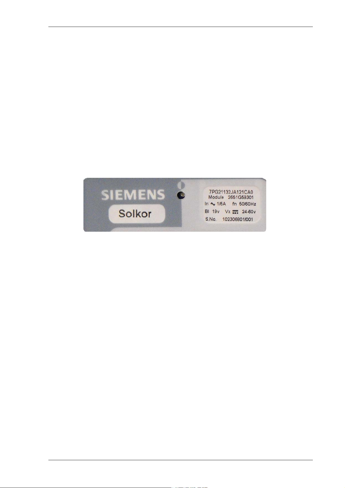
Relay Information
Above the LCD two labels are provided, these provide the following information:
1) Product Information & Rating Label, containing
MLFB ordering code
Nominal current rating
Rated frequency
Voltage rating
Auxiliary supply rating
Binary input supply rating
Serial number
2) Purpose inscription label marked ‘Solkor’.
Figure 2.5-2 Close up of typical relay labels
A ‘template’ is available in Reydisp Software to allow users to create and print customised purpose inscription
labels.
©2010 Siemens Protection Devices Limited Chapter 1 Page 18 of 80
7PG2113/4/5/6 Solkor Description of Operation
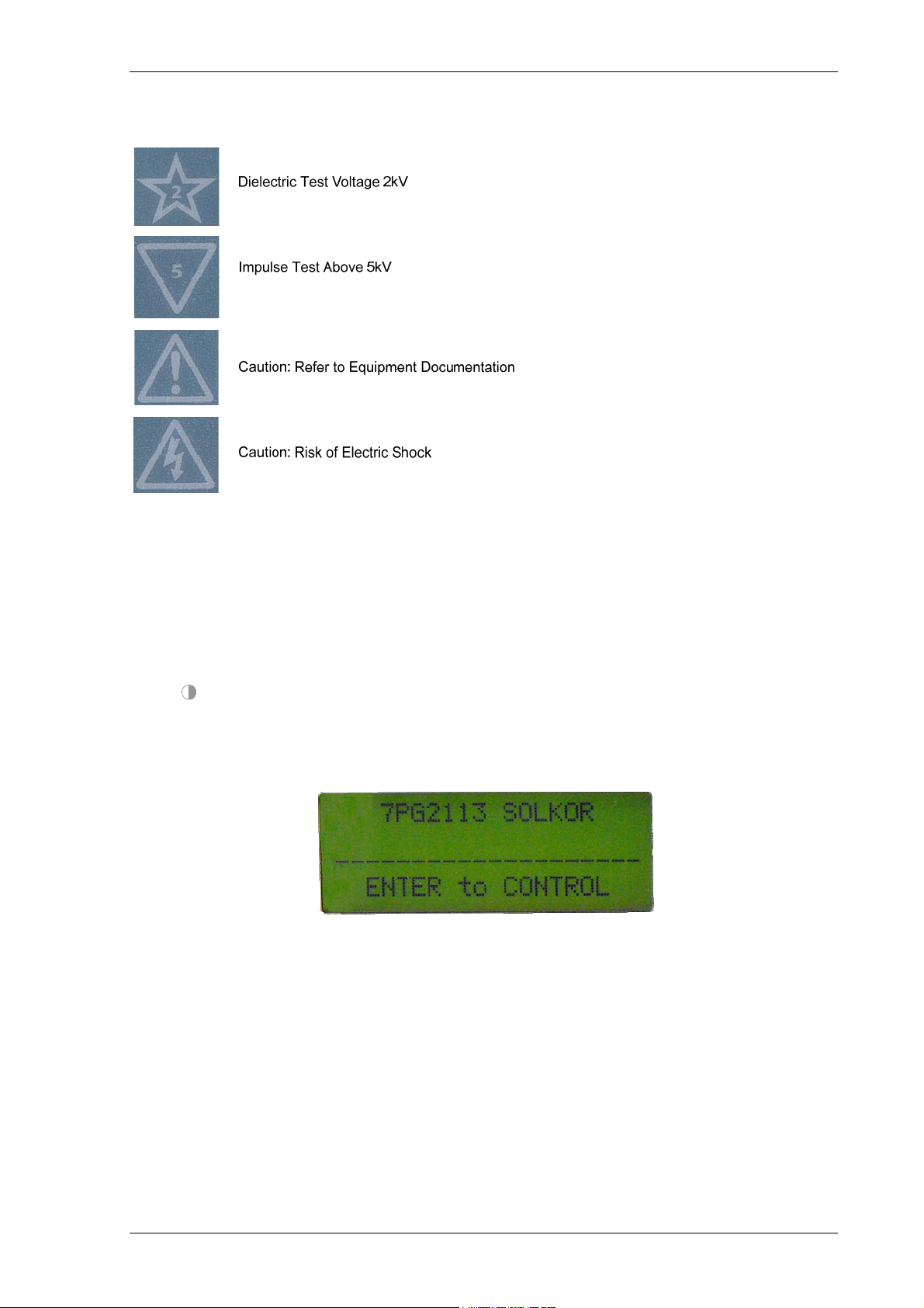
For safety reasons the following symbols are displayed on the fascia
Liquid Crystal Display (LCD)
A 4 line by 20-character alpha-numeric liquid crystal display indicates settings, instrumentation, fault data and
control commands.
To conserve power the display backlighting is extinguished when no buttons are pressed for a user defined
period. The ‘backlight timer’ setting within the “SYSTEM CONFIG” menu allows the timeout to be adjusted from 1
to 60 minutes and “Off” (backlight permanently on). After an hour the display is completely de-activated. Pressing
any key will re-activate the display.
The LCD contrast can be adjusted using a flat blade screwdriver to turn the screw located below the contrast
symbol
. Turning the screw clockwise increases the contrast, anti-clockwise reduces the contrast.
User defined indentifying text can be programmed into the relay using the System config/Relay Identifier
setting. The ‘Relay Identifier’ text is displayed on the LCD display at the top level of the menu structure and is
used in communication with Reydisp to identify the relay. Pressing the Cancel button several times will always
return the user to this screen.
Figure 2.5-3 Close up of Relay Identifier
©2010 Siemens Protection Devices Limited Chapter 1 Page 19 of 80

7PG2113/4/5/6 Solkor Description of Operation
LCD Indication
General Alarms are user defined text messages displayed on the LCD when mapped to binary or virtual inputs.
Up to six general alarms of 16 characters can be programmed, each triggered from one or more input. Each
general alarm will also generate an event.
If multiple alarms are activated simultaneously the messages are displayed on a separate page
in a rolling display on the LCD.
All general alarms raised when a fault trigger is generated will be logged into the Fault Data record.
Standard Keys
The relay is supplied as standard with five pushbuttons. The buttons are used to navigate the menu structure and
control relay functions. They are labelled:
▲ Increases a setting or moves up menu.
▼ Decreases a setting or moves down menu.
TEST/RESET► Moves right, can be used to reset selected functionality and for LED test (at
relay identifier screen).
ENTER Used to initiate and accept settings changes.
CANCEL Used to cancel settings changes and/or move up the menu structure by one
level per press.
NOTE: All settings and configuration of LEDs, BI and BO can be accessed and set by the user using these keys.
Alternatively configuration/settings files can be loaded into the relay using ‘Reydisp’. When the System
Config>Setting Dependencies is ENABLED, only the functions that are enabled will appear in the menu
structure.
‘PROTECTION HEALTHY’ LED
This green LED is steadily illuminated to indicate that DC voltage has been applied to the relay power supply and
that the relay is operating correctly. If the internal relay watchdog detects an internal fault then this LED will
continuously flash.
Indication LEDs
Relays have 9 user programmable LED indicators. Each LED can be programmed to be illuminated as either
green, yellow or red. Where an LED is programmed to be lit both red and green it will illuminate yellow. The same
LED can be assigned two different colours dependent upon whether a Start/Pickup or Operate condition exists.
LED’s can be assigned to the pick up condition and colour selected in the OUTPUT CONFIG>LED CONFIG
menu.
Functions are assigned to the LEDs in the OUTPUT CONFIG>OUTPUT MATRIX menu.
Each LED can be labelled by withdrawing the relay and inserting a label strip into the pocket behind the front
fascia. A ‘template’ is available in the Reydisp software tool to allow users to create and print customised legends.
Each LED can be user programmed as hand or self–resetting. Hand reset LEDs can be reset by either pressing
the TEST/RESET► button, energising a suitably programmed binary input, or, by sending an appropriate
command over the data communications channel(s).
The status of hand reset LEDs is maintained by a back up storage capacitor in the event of an interruption to the
d.c. supply voltage.
©2010 Siemens Protection Devices Limited Chapter 1 Page 20 of 80
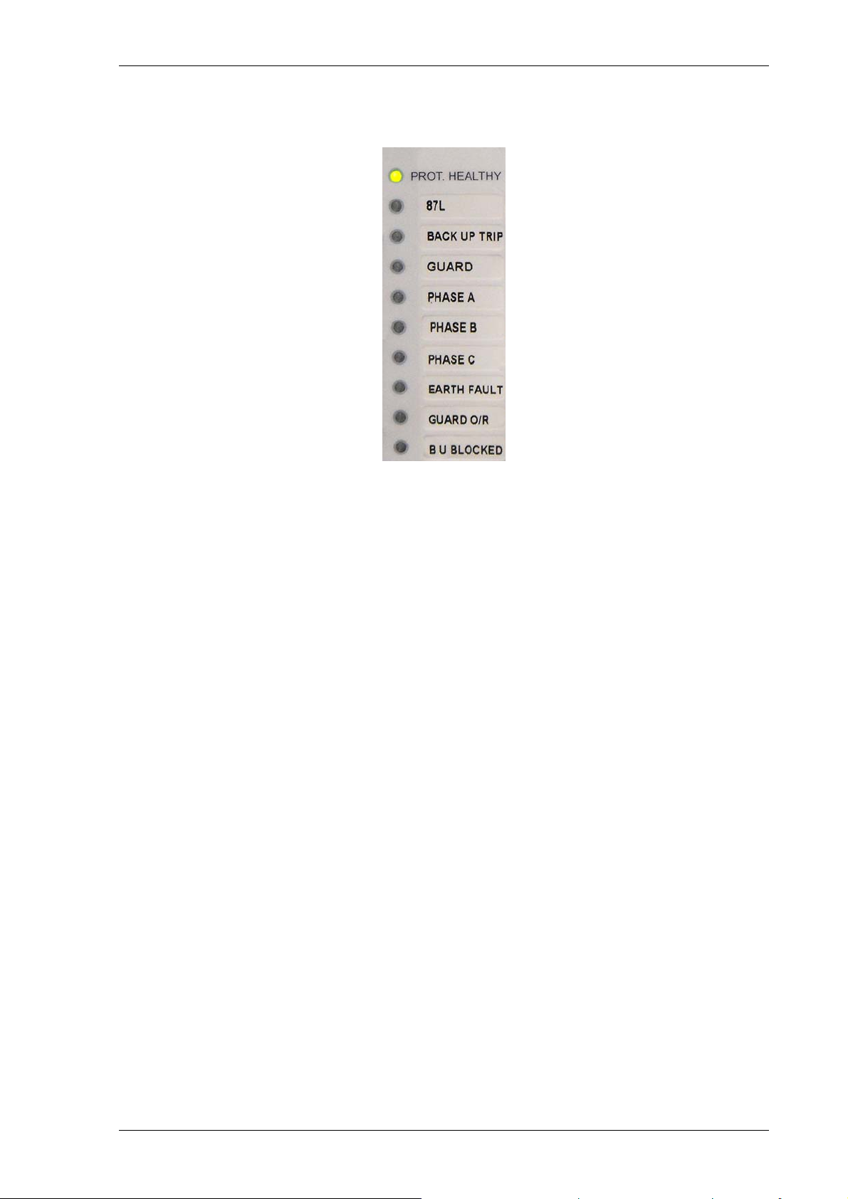
7PG2113/4/5/6 Solkor Description of Operation
Figure 2.5-4 LED Indication Label
2.6 Current Inputs
Four current inputs are provided on the Numeric module. Terminals are available for both 1A and 5A inputs.
The correct connections must be applied to suit the fixed 1A or 5A rating of the Solkor R/Rf module.
Current is sampled at 1600Hz for both 50Hz and 60Hz system frequencies. Protection and monitoring functions of
the relay use either the Fundamental Frequency RMS or the True RMS value of current appropriate to the
individual function.
The waveform recorder samples and displays current input waveforms at 1600Hz.
2.7 Voltage Inputs
Three voltage inputs are provided on the Analogue Input module of the 7PG2114/6 relays.
Voltage is sampled at 1600Hz for both 50Hz and 60Hz system frequencies. Protection and monitoring functions of
the relay use fundamental frequency voltage measurement.
The waveform recorder samples and displays voltage input waveforms at 1600Hz.
©2010 Siemens Protection Devices Limited Chapter 1 Page 21 of 80
7PG2113/4/5/6 Solkor Description of Operation
2.8 Binary Inputs
The binary inputs are operated from a suitably rated dc supply.
Relays are fitted with 3 or 6 binary inputs (BI) depending on the variant. One BI should be wired externally to the
Solkor R/Rf module to take advantage of the recording and indication functions of the numeric module. The user
can assign any binary input to any of the available functions (INPUT CONFIG > INPUT MATRIX).
Pick-up (PU) and drop-off (DO) time delays are associated with each binary input. Where no pick-up time delay
has been applied the input may pick up due to induced ac voltage on the wiring connections (e.g. cross site
wiring). The default pick-up time of 20ms provides ac immunity. Each input can be programmed independently.
Each input may be logically inverted to facilitate integration of the relay within the user scheme. When inverted the
relay indicates that the BI is energised when no d.c. is applied. Inversion occurs before the PU & DO time delay,
see fig. 2.8-1.
Each input may be mapped to any front Fascia indication LED and/or to any Binary output contact and can also
be used with the internal user programmable logic. This allows the relay to provide panel indications and alarms.
Each binary input is set by default to be read when the relay is in both the local or remote condition. A setting is
provided to allow the user to select if each individual input shall be read when the relay is in the local or remote
condition in the INPUT CONFIG > BINARY INPUT CONFIG menu.
Binary Input 1
Binary Input n
Inverted Inputs
BI 1 inverted
INPUT
CONFIG>
BINARY
INPUT
CONFIG
BI n inverted
=1
=1
BI 1 P/U Delay
BI n P/U Delay
BI 1 D/O Delay
BI n D/O Delay
BI 1
Event
BI n
Event
INPUT CONFIG>
INPUT MATRIX
(Or gates)
Logic signals,
e.g. '51-1 Inhibit'
Figure 2.8-1 Binary Input Logic
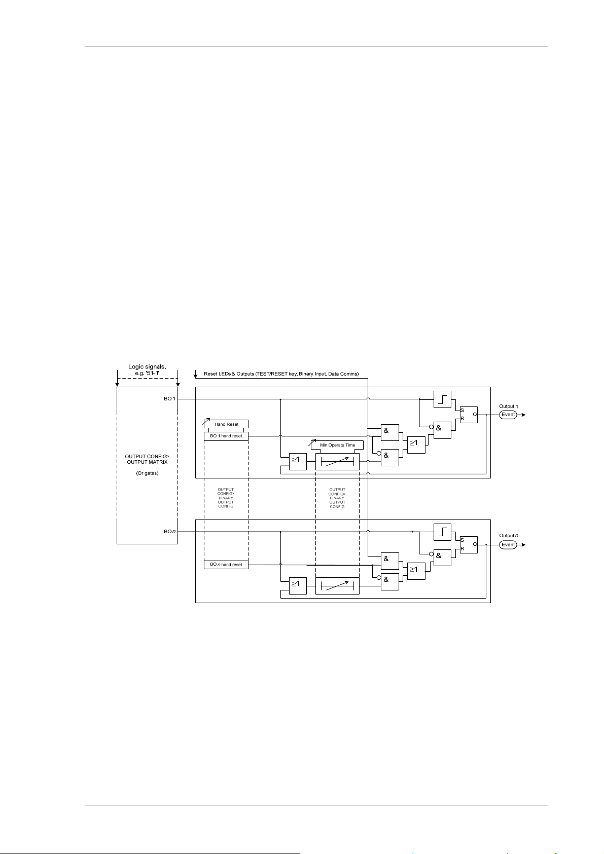
2.9 Binary Outputs (Output Relays)
The Solkor R/Rf module provides 3 segregated voltage free normally open contacts. The functionality of these
contacts is fixed. One contact must be wired externally to the numeric module to take advantage of the recording
and indication functions of that module. Numeric modules are fitted with 5 or 8 binary outputs (BO). All outputs of
the numeric module are fully user configurable and can be programmed to operate from any or all of the available
functions.
In the default mode of operation the binary outputs of the numeric module are self reset and remain energised for
a user configurable minimum time of up to 60 seconds. If required, these outputs can be programmed to operate
as ‘hand reset’ or ‘pulsed’. If the output is programmed to be ‘hand reset’ and ‘pulsed’ then the output will be
‘hand reset’ only.
The output contacts can be used to operate the trip coils of the circuit breaker directly where the trip coil current
does not exceed the 'make and carry' contact rating. The circuit breaker auxiliary contacts or other in-series
auxiliary device must be used to break the trip coil current. It is recommended that the trip signal to the circuit
breaker is wired directly from the Solkor R/Rf module rather than via the numeric module for maximum speed and
simplicity.
©2010 Siemens Protection Devices Limited Chapter 1 Page 22 of 80
7PG2113/4/5/6 Solkor Description of Operation
Any BO can be assigned as a ‘Trip Contact’ in the OUTPUT CONFIG>TRIP CONFIG menu. Operation of a ‘Trip
Contact’ will operate any LED or virtual assigned from the trip triggered feature in the same menu and will initiate
the fault record storage, actuate the ‘Trip Alert’ screen where enabled and CB Fail protection when enabled.
The following notes refer to the binary outputs of the numeric module:
Notes on Pulsed Outputs
When operated, the output will reset after a user configurable time of up to 60 seconds regardless of the initiating
condition.
Notes on Self Reset Outputs
Self reset operation has a minimum reset time of 100ms
With a failed breaker condition the relay may remain operated until current flow is interrupted by an upstream
device. When the current is removed the relay will then reset and attempt to interrupt trip coil current flowing via
its output contact. Where this current level is above the break rating of the output contact an auxiliary relay with
heavy-duty contacts should be utilised in the primary system to avoid damage to the relay.
Notes on Hand Reset Outputs
Hand reset outputs can be reset by either pressing the TEST/RESET► button, by energising a suitably
programmed binary input, or, by sending an appropriate command over the data communications channel(s).
On loss of the auxiliary supply hand-reset outputs will reset. When the auxiliary supply is re-established the binary
output will remain in the reset state unless the initiating condition is still present.
Binary Output Test
Figure 2.9-1 Binary Output Logic
©2010 Siemens Protection Devices Limited Chapter 1 Page 23 of 80

7PG2113/4/5/6 Solkor Description of Operation
2.10 Virtual Input/Outputs
The relays have 8 virtual input/outputs, these are internal logic states. Virtual I/O is assigned in the same way as
physical Binary Inputs and Binary Outputs. Virtual I/O is mapped from within the INPUT CONFIG > INPUT
MATRIX and OUTPUT CONFIG > OUTPUT MATRIX menus.
The status of the virtual inputs and outputs is volatile i.e. not stored during power loss.
2.11 Self Monitoring
The relay incorporates a number of self-monitoring features. Each of these features can initiate a controlled reset
recovery sequence.
Supervision includes a power supply watchdog, code execution watchdog, memory checks by checksum and
processor/ADC health checks. When all checks indicate the relay is operating correctly the ‘Protection Healthy’
LED is illuminated.
If an internal failure is detected, a message will be displayed. The relay will reset in an attempt to rectify the
failure. This will result in de-energisation of any binary output mapped to ‘protection healthy’ and flashing of the
protection healthy LED. If a successful reset is achieved by the relay the LED and output contact will revert back
to normal operational mode, and the relay will restart.
2.11.1 Protection Healthy/Defective
When the relay has an auxiliary DC supply and it has successfully passed its self-checking procedure then the
front facia Protection Healthy LED is turned on.
A changeover or open contact can be mapped via the binary output matrix to provide an external protection
healthy signal.
A changeover or closed contact can be mapped via the binary output matrix to provide an external protection
defective signal. With the ‘Protection Healthy’ this contact is open. When the auxiliary DC supply is not applied to
the relay or a problem is detected within the relay then this output contact closes to provide external indication.
If the relay is withdrawn from the case, the case shorting contact will make across the normally closed contacts to
provide and external alarm.
©2010 Siemens Protection Devices Limited Chapter 1 Page 24 of 80
7PG2113/4/5/6 Solkor Description of Operation
Section 3: Current Differential Protection Function
3.1 Description
Conjunctive operation of the Current Differential function and the Overcurrent and Earth Fault Guard functions is
described in the Applications section of this manual.
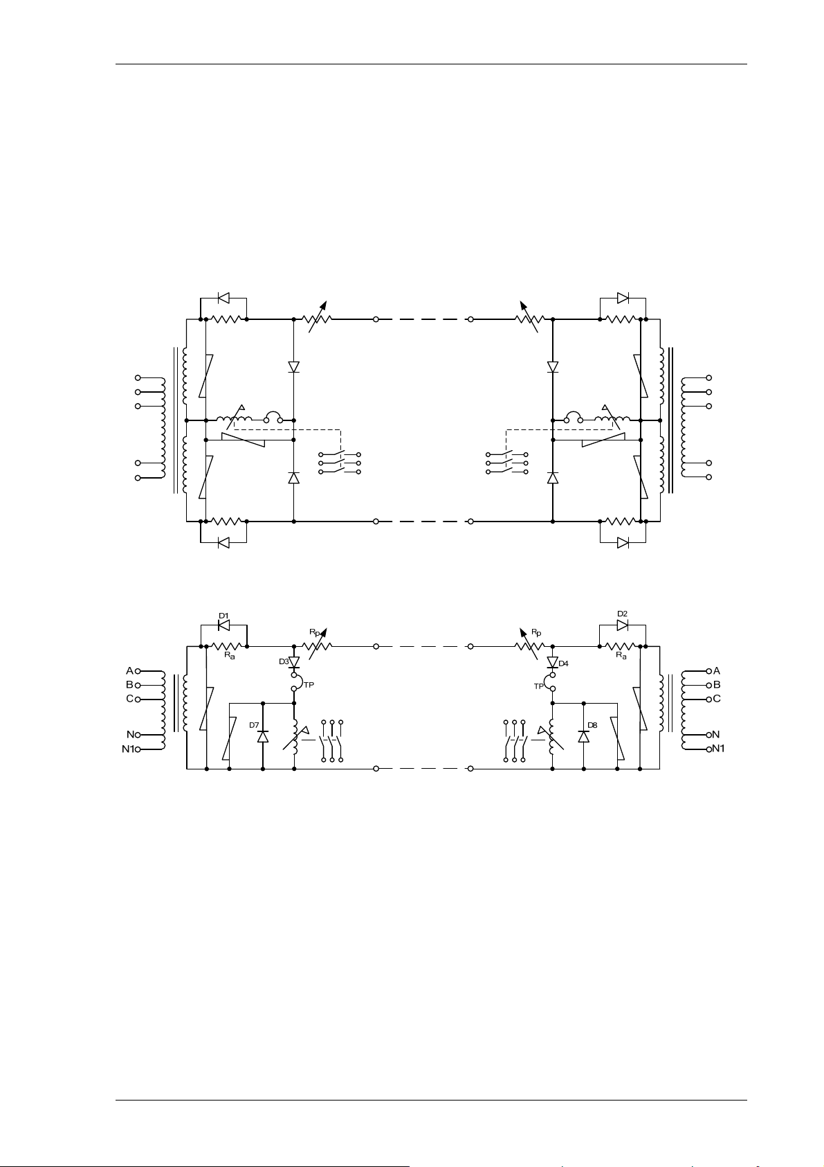
The Solkor Rf protection system (excluding current transformers) is shown below. The alternative basic Solkor R
protection circuit is also shown
D1
R
a
.
D2
R
p
R
p
R
a
N1
A
B
C
N
R
a
D5
D3
TP
D7
D4
TP
D8
R
a
D6
A
B
C
N
N1
Figure 3.1-1 Solkor Rf schematic
Figure 3.1-2 Solkor R schematic
Selection of the Solkor Rf or Solkor R operating mode is arranged by wire links, internal to the relay.
The relay contains an 8-way internal terminal block. 4 wires marked 1-4 must be moved from 4 terminals marked
‘Solkor Rf’ to 4 adjacent terminals marked ‘Solkor R’. Additionally a wire link must be fitted, externally to the relay
on the rear terminal block to use the relay in Solkor R mode.
In addition to the basic components there are at each end, three non-linear resistors, a tapped ‘padding’ resistor
and three diodes. The non-linear resistors are used to limit the voltage appearing across the pilots and the
operating element. The purpose of the ‘padding’ resistors at each end is to bring the total pilot loop resistance up
to a standard value. The protection is therefore always working under constant conditions and its performance is
to a large extent, independent of the resistance of the pilot cable’ The ‘padding’ resistors comprise five series
connected sections, each section having a short circuiting link. The values of the resistance on the sections are
35 ohms, 65 ohms, 130 ohms, 260 ohms and 500ohms.
For Solkor R the value chosen should be as near as possible to ½(1000-R
resistance. The 500 ohm resistor should therefore never be fitted for the Solkor R and the link will always be fitted
for this mode.
©2010 Siemens Protection Devices Limited Chapter 1 Page 25 of 80
) ohms, where Rp is the pilot
p
7PG2113/4/5/6 Solkor Description of Operation
For Solkor Rf without isolating transformers the value chosen should be as near as possible to ½(2000-Rp) ohms.
For Solkor Rf with isolating transformers the value chosen should be as near as possible to
½(SV-R
)/T ohms.
p
where T = Isolating transformer tap.
& SV = Standard resistance value for tap on transformers,
1780Ω for tap1, 880Ω for tap 0.5 & 440Ω for tap 0.25
The operating element is of the attracted armature type with three contacts, each pair being brought out to
separate terminals. The inherent advantages of such a relay are robustness and simplicity and since the contacts
are suitable for direct operation of a circuit breaker trip coil, no repeat relay is necessary.
A 5kV insulation level is provided between the secondary winding of the summation transformer and its primary
winding. The core and the relay coil is also insulated at 5kV.
Since the only external connections to the relay are those to; the current transformers, the pilots and the tripping
and alarm circuits, the installation and commissioning of the equipment is extremely simple. To check the current
in the operating element, a test point is provided.
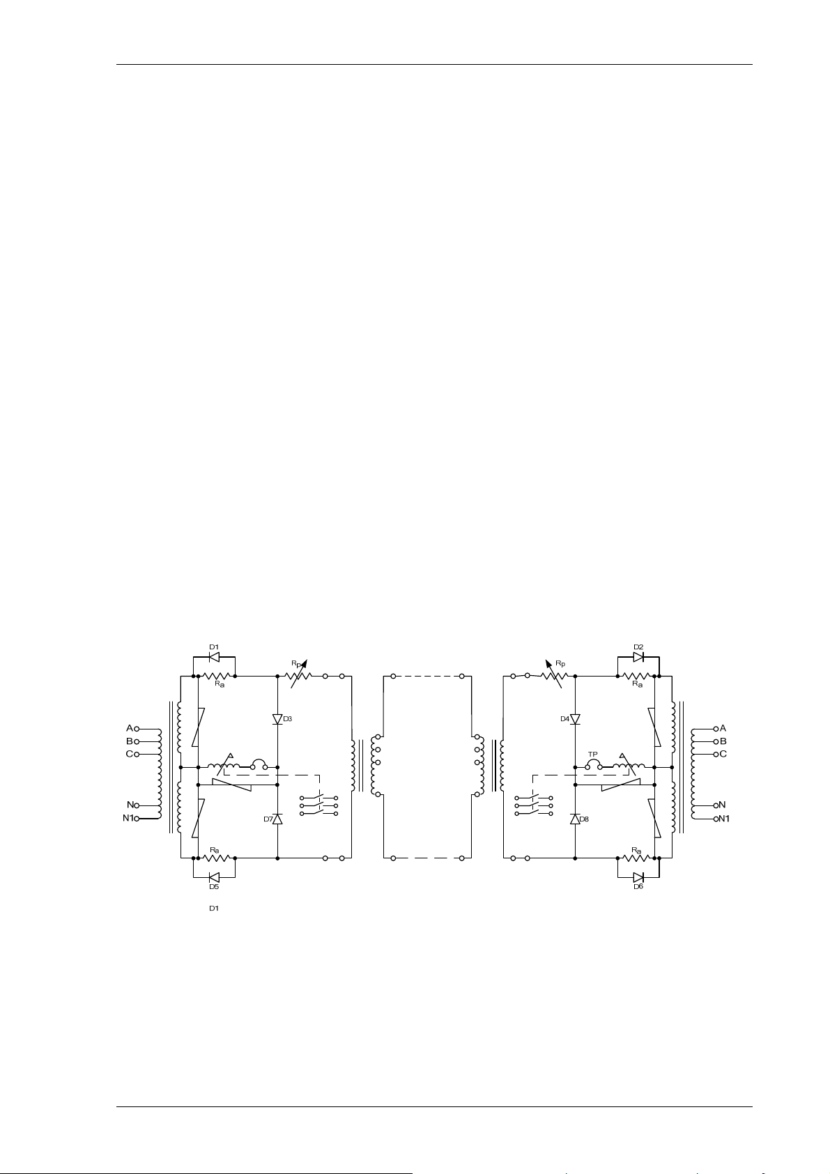
The 15kV arrangement is for applications where the voltage across the pilot insulation due to induction or a rise in
station earth potential are excessive and where, consequently, the normal 5kV insulation level is not considered
adequate.
The complete protection scheme is shown in figure below.
Figure 3.1-3 Solkor Rf 15kV schematic
The difference between this circuit and that shown previously is that the pilots are connected via interposing
transformers which incorporate 15kV insulation barriers between windings to isolate the pilot circuit. The
introduction of the isolating transformer does not modify the basic principle of operation of the protection but
allows greater range of pilot coverage by the use of taps on the isolating transformer secondary windings.
©2010 Siemens Protection Devices Limited Chapter 1 Page 26 of 80

7PG2113/4/5/6 Solkor Description of Operation
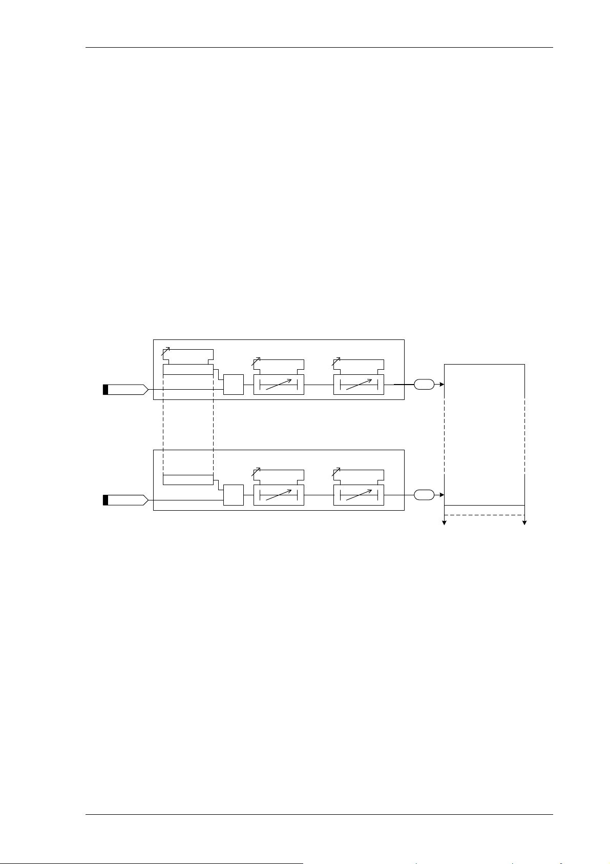
3.2 Operation
Solkor R belongs to the circulating current class of differential protections which can be recognised by two main
features. Firstly, the current-transformer secondaries are arranged to produce a current circulating around the
pilot loop under external fault conditions. Secondly, the protective relay operating coils are connected in shunt
with the pilots across points which have the same potential when the current circulates around the pilot loop. In
this particular scheme equipotential relaying points during external fault conditions exist at one end during one
half cycle of fault current, and at the other end during the next half cycle. During half cycles when the relay at
either end is not at the electrical midpoint of the pilot system the voltage appearing across the relay is in the
reverse direction to that required for operation.
At each end of the feeder the secondaries of the current transformers are connected to the primary of the
summation transformer – see section 3.3 Theory of Summation Transformer. For various types of current
distribution in the three current transformers, a single phase quantity appears in the summation transformer
secondary winding and is applied to the pilot circuit. By this means a comparison between the currents at each
end of a three phase line is effected over a single pair of pilot wires on an equivalent single phase basis. The
tappings on the summation transformer primary have been selected to give an optimum balance between the
demands of fault setting and stability.
The pilot is shown as a ‘lumped’ resistor RP. The rest of the pilot loop is made up of four resistors Ra and four
diodes D1, D2, D5 and D6. The operating elements, which are made unidirectional by diodes D3, D4, D7 and D8
are connected in shunt with the pilots.
During an external fault condition, an alternating current circulates around the pilot loop. Thus on successive half
cycles one or other of the resistors R
D2. The total resistance in each leg of the pilot loop at any instant is therefore substantially constant and equal to
Ra+Rp. The effective position of Ra however, alternates between ends, being dependent upon the direction of the
current. The change in the effective position of R
for successive half-cycles of the pilot current.
In other words stability is achieved by current balance using the Solkor R principle of establishing the electrical
centre point geographically within the end which has positive polarity so that the positively polarised measuring
elements remain in the negative part of the circuit and are thus biased against operation.
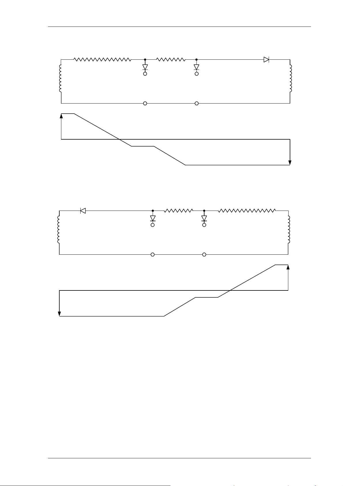
Referring to the basic circuit of Solkor Rf as shown in Figure 3.1-2, the circulating current will flow from the
summation transformer through the diode or the resistor depending on the polarity of the summation transformer
output. Thus the circuit may be redrawn to suit the polarities of summation transformer output as shown in Figure
3.2-1 & Figure 3.2-2 below.
at the two ends of the pilot is short circuited by its associated diode D1 or
a
makes the voltage distribution between the pilot cores different
a
©2010 Siemens Protection Devices Limited Chapter 1 Page 27 of 80
7PG2113/4/5/6 Solkor Description of Operation
R
A
a
+
B
D3
R
p
C
D4
D2
D
-
W Z
XY
A
XYW Z
B
C
Figure 3.2-1 Through Fault, zero ohm pilots, Positive half cycle.
R
A
-
D1
B
D3
p
C
D4
+
YX
R
a
+
D
D
+
-
XW
D
YXZW
C
B
A
Figure 3.2-2 Through Fault, zero ohm pilots, Negative half cycle.
Figure 3.2-1 & Figure above represents the operations of Solkor R protection with zero ohm pilots so that the
loop resistance is represented entirely by the 500 ohm padding resistor in each relay and the 1000ohm sum in the
pilot circuit is in one leg of the pilot circuit as shown, RP.
Resistors Ra are of greater resistance than the pilot loop resistance Rp and this causes the point of zero potential
to occur within the resistors R
, as shown in Figure 3.2-1. The voltage across each relaying point (B-X and C-Y)
a
throughout the cycle is now always negative. This voltage bias must be overcome before operation can take
place; consequently the effect is to enhance the stability of the protection against through faults.
©2010 Siemens Protection Devices Limited Chapter 1 Page 28 of 80
 Loading...