

Siemens Solaris CCDS1415-ST,Solaris CCDS1415-DN,Solaris CCDS1415-DNX Configuration Manual
Fire Safety & Security Products
Siemens Building Technologies
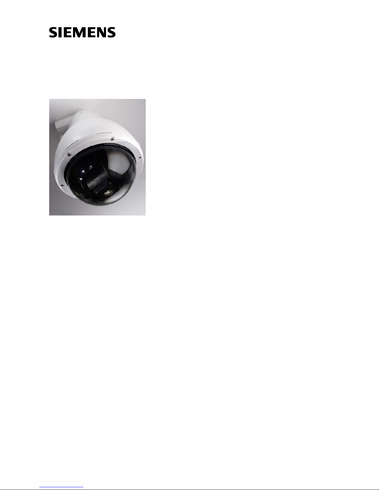
Solaris™ Dome
CCDS1415-ST
CCDS1415-DN
CCDS1415-DNX
Configuration Manual

Liefermöglichkeiten und technische Änderungen vorbehalten.
Data and design subject to change without notice. / Supply subject to availability.
© 2006 Copyright by
Siemens Building Technologies AG
Wir behalten uns alle Rechte an diesem Dokument und an dem in ihm dargestellten Gegenstand vor. Der Empfänger erkennt diese Rechte
an und wird dieses Dokument nicht ohne unsere vorgängige schriftliche Ermächtigung ganz oder teilweise Dritten zugänglich machen oder
außerhalb des Zweckes verwenden, zu dem es ihm übergeben worden ist.
We reserve all rights in this document and in the subject thereof. By acceptance of the document the recipient acknowledges these rights
and undertakes not to publish the document nor the subject thereof in full or in part, nor to make them available to any third party without our
prior express written authorization, nor to use it for any purpose other than for which it was delivered to him.
Copyright
Copyright 2006 © Fire & Security Products GmbH & Co. oHG. All rights reserved.
Siemens Fire & Security Products GmbH & Co. oHG confers upon the purchaser
the right to use the software.
It is not permitted to reproduce this document in whole or in part or translate it into
another language without our written consent.
Trademarks
Solaris
TM
is a trademark of Fire & Security Products GmbH & Co. oHG.
Microsoft is a registered trademark and Windows a trademark of Microsoft
Corporation. All other products or company names referred to explicitly in this
manual are mentioned only for purposes of identification or description and may be
trademarks or registered trademarks of their respective owners.
Contacting us
If you have questions or suggestions regarding the product or this documentation,
please contact your local SIEMENS representative.
Siemens Building Technologies
Fire & Security Products GmbH & Co. oHG
D-76181 Karlsruhe
You can also visit our Web site at www.sbt.siemens.com
.
Training courses
Siemens Fire Safety & Security Products provides training courses for all products.
About this document
This manual provides the information you will need in order to install and configure
a Solaris™ Dome unit. We recommend that you read through it at least once
before you begin the installation.
Orientation guide
Tips and information

3
Siemens Building Technologies
Fire Safety & Security Products 08.2006
Contents
1 Functional description ...........................................................................5
2 Safety .......................................................................................................6
2.1 Target readers...........................................................................................6
2.2 General safety precautions .......................................................................6
2.3 Meaning of the signal words .....................................................................8
2.4 Meaning of the hazard symbols................................................................8
3 Guidelines and standards ...................................................................... 9
3.1 EU directives.............................................................................................9
3.2 FCC compliance........................................................................................9
4 Technical data .......................................................................................10
4.1 Dome.......................................................................................................10
4.2 Camera module.......................................................................................11
5 Ordering information ............................................................................ 12
6 Scope of delivery ..................................................................................13
7 Unit description..................................................................................... 14
8 Installation of the Dome unit................................................................15
8.1 Tools required .........................................................................................15
8.2 Installation procedure..............................................................................16
8.3 Installing the mounting brackets .............................................................17
8.3.1 Wall/Ceiling mount CCDS1415-WM .......................................................17
8.3.2 Corner mount adapter CCDS1415-CMA ................................................18
8.3.3 Parapet mount adapter CCDS1415-BM .................................................19
8.3.4 Pendant mount CCDS1415-PM.............................................................. 20
8.3.5 Pole fixture (using wall mount CCDS1415-WM).....................................21
8.3.6 Recessed ceiling tile mount CCDS1415-FM ..........................................21
8.4 Preparing the Dome bracket ...................................................................23
8.5 Cat5 cable assembly and disassembly...................................................25
8.5.1 Assembly.................................................................................................26
8.5.2 Disassembly............................................................................................29
8.6 Connecting the Solaris™ Dome..............................................................30
9 Installation of the External Termination Unit (XTU)...........................31
9.1 Unit description .......................................................................................31
9.2 Installation procedure..............................................................................31
9.2.1 Choosing a location for the XTU.............................................................32
9.2.2 Mounting the XTU ...................................................................................32
9.3 Connecting the XTU to external equipment............................................33
9.4 Description of the connections................................................................ 33
9.4.1 XTU connections - coaxial (C-type) telemetry ........................................35
9.4.2 XTU connections - RS485 (D-type) telemetry ........................................36
9.4.3 XTU connections - Photon telemetry ......................................................37
9.5 Wiring guide ............................................................................................38
10 Configuration of the External Termination Unit.................................39
10.1 Keys and their functions..........................................................................39
10.2 LCD orientation .......................................................................................40
10.3 The XTU main menu...............................................................................40
10.4 XTU setup ...............................................................................................42

4
Siemens Building Technologies
Fire Safety & Security Products 08.2006
11 Configuration of the Dome unit ...........................................................43
11.1 On-screen display menus .......................................................................43
11.1.1 The Passcodes menu .............................................................................44
11.1.2 The Camera menu ..................................................................................45
11.1.3 The Presets, Tours and Patterns menu ..................................................47
11.1.4 The Privacy Zones menu ........................................................................49
11.1.5 The Soft Limits and Sectors menu..........................................................50
11.1.6 The Alarm menu......................................................................................51
11.1.7 The OSD menu .......................................................................................53
11.1.8 The Diagnostics menu ............................................................................54
12 Telemetry controller operation and setup..........................................55
12.1 Telemetry keyboard operation ................................................................55
12.1.1 Access to the OSD with Siemens controllers..........................................55
12.1.2 Access to the OSD with Bewator controllers ..........................................56
12.1.3 Access to the OSD with 3rd party controllers .........................................56
12.2 Advanced camera functions....................................................................57
12.3 Use with Siemens controllers..................................................................57
12.3.1 Direct control via CKA48xx/CKA32xx .....................................................58
12.3.2 Control via SIMATRIX NEO and dome converter CAC0103 ..................59
12.4 Use with Bewator controllers...................................................................60
12.4.1 Molynx & Molynx V3................................................................................60
12.4.2 PCCON, PCCON 1-way and PCCON MULTIDROP ..............................61
12.5 Use with 3rd party controllers..................................................................63
12.5.1 Pelco P & D protocols .............................................................................63
12.5.2 Ernitec ERNA protocol ............................................................................64
12.5.3 VCL protocol............................................................................................65
12.5.4 Videmech Universal protocol ..................................................................65
12.5.5 Photon protocol .......................................................................................66
12.5.6 Vicon protocol .........................................................................................66
12.5.7 Philips protocol........................................................................................67
13 Maintenance...........................................................................................68
13.1 Dismantling the Solaris™ Dome .............................................................68
13.2 Monthly checks .......................................................................................69
13.3 Bubble maintenance ...............................................................................69
14 Disposal .................................................................................................70
15 Keyword index.......................................................................................71

5
Siemens Building Technologies
Fire Safety & Security Products 08.2006
1 Functional description
Breaking away from the commonly available domes on the market the new
Solaris™ Dome offers a level of accuracy, speed and configurability never
experienced before. Solaris™ is available for both internal and external use so you
can utilise your security system to the full. Underneath the contemporary styling of
the Dome’s cover is a fully featured camera unit designed to put the operator in full
control.
Under manual control, pan and tilt speed is proportional to the degree of zoom
allowing accurate target tracking, whilst high speed preset acquisition permits near
instantaneous response to alarms. Solaris™ Domes include the following features:
– Colour and Day/Night versions both with 24 privacy masks.
– Pan and Tilt Preset acquisition within 1 second, Tours, Patterns, Preset and
Sector texts.
– 7 local alarms and tamper.
Designed with reliability, ease of install and ease of use as priorities, Solaris™
comes with a range of innovative features. The unit is supplied as two halves - the
Dome Unit containing the camera and positioning system, and the External
Termination Unit (XTU).
The XTU separates the power, video, telemetry and alarm cable terminations from
the Dome itself; and provides a low voltage power supply for the Dome contained
within a weather-proof housing. Address and protocol selection is via a menu
driven LCD display in the XTU, avoiding the issue of remembering switch and links
settings. This means, for most applications the installer need never open the Dome
camera’s enclosure. A single 10 m cable is supplied to connect the XTU to the
Dome unit.
Solaris™ is a multi-protocol Dome suitable for use with a range of industry
standard control equipment. It can be controlled via Siemens CCDA protocol over
RS485, bi-directional Molynx protocol over RS485 or coax, or alternatively using
Ernitec, Pelco D, Pelco P or VCL, Videmech Universal, Photon and PCCON
protocols over RS485. Once the receiver address, the protocol and interface have
been configured using the XTU, all other configuration can be done remotely via
the pass code protected on-screen display (OSD) menus.
Using the OSD Solaris™ Domes can be configured in flexible ways making them
powerful security system components with:
– Configurable alarm and idle state time out actions
– Functions can also be assigned to preset numbers
– Programmable video launch amplifier
– On-screen diagnostics and usage stats
– Installer programmable on-screen text for contact details or inventory number
– Access to camera module configuration via OSD
6
Siemens Building Technologies
Fire Safety & Security Products 08.2006
2 Safety
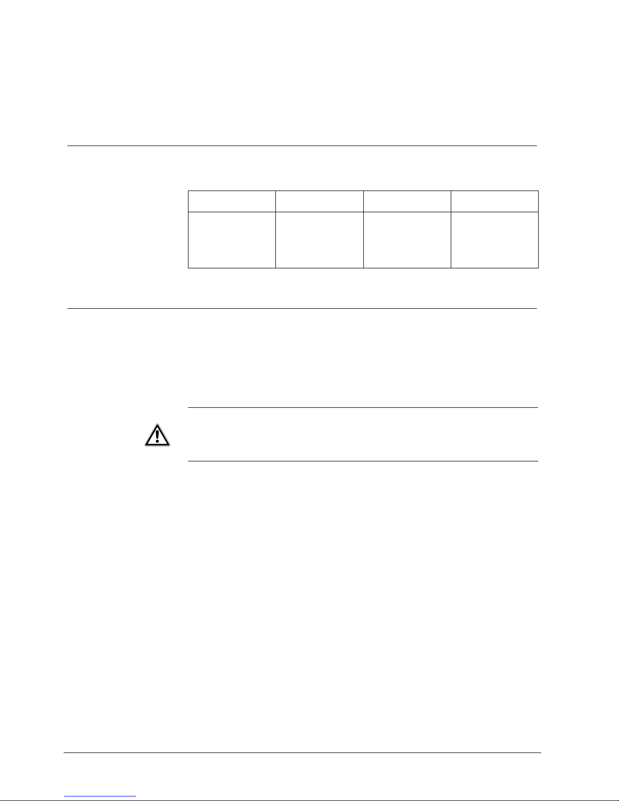
2.1 Target readers
The instructions in this document are designed only for the following target
readers:
Target readers Qualification Activity Condition of the
equipment
Start-up personnel Appropriate
professional training
regarding the function
and units or systems to
be brought into
operation.
Start-up personnel bring
the unit or system which
has been installed into
operation on-site.
New, installed, rebuilt
unit or system with
malfunction.
2.2 General safety precautions
– Read the general safety precautions before operating the unit.
– Follow all warnings and instructions marked on the device.
– Keep this document available for reference.
– If the product is passed on to another party, include this document.
CAUTION
This device must be earthed.
A readily accessible disconnect device shall be incorporated in the building
installation wiring.
As part of the building installation protect this device via a 3 A fuse or 3 A circuit
breaker.
The Solaris™ Dome should be installed by competent, qualified personnel in
accordance with the latest national standards.
These include:
– NACOSS National Approval Council for Security Systems
– NACP20 Code of Practice for installation and maintenance of Closed Circuit
Television Systems
– IEE Requirements for Electrical Installations, BS 7671
– UK Data Protection Act 1998 - CCTV Data Protection Codes of Practice
Radio interference with other devices in the environment
This is a Class A device. This equipment may cause radio interference in a
residential installation. In this case the user is encouraged to perform appropriate
measures to correct the interference.

7
Siemens Building Technologies
Fire Safety & Security Products 08.2006
Liability claim
– Do not connect the device if any parts are missing or damaged.
– Do not make any changes or modifications to the device that are not mentioned
in this manual and that have not been approved by the manufacturer.
– Use only spare parts and accessories that have been approved by the
manufacturer.
Damage during transport
– Keep the packaging material for future transportation.
– Do not expose the device to mechanical vibrations or shocks.
Cable damage due to mechanical load
When connecting the cables, do not apply tensile force and make sure not to bend
or damage them.
Damage due to unsuitable mounting location
– The environmental conditions recommended by the manufacturer must be
observed. See Section: 4 Technical data.
– Do not operate the device close to sources of powerful electromagnetic
radiation.
– Do not operate the device in excessively dusty places.
– Do not operate the device where it is exposed to mechanical vibrations.
Damage to the device due to overvoltage
Connect the device only to power sources with the specified voltage. Voltage
supply requirements can be found on the power supply unit/type label. See
Section: 4 Technical data.
Danger of electrical shock and damage to the device
Electrical grounding must meet the customary local safety regulations.
Data loss after update
Make sure to backup all data before updating the device.
Electric shock or fire hazard
Never insert objects through the openings on the device.
Danger of electrical shock during maintenance
Always disconnect the power cable and other cables from the main power supply
before performing maintenance.
Danger of electrical shock while cleaning the device
– Disconnect the device from the mains supply before cleaning it.
– Do not use liquid cleaners or sprays that contain alcohol, spirit or ammonia.
8
Siemens Building Technologies
Fire Safety & Security Products 08.2006
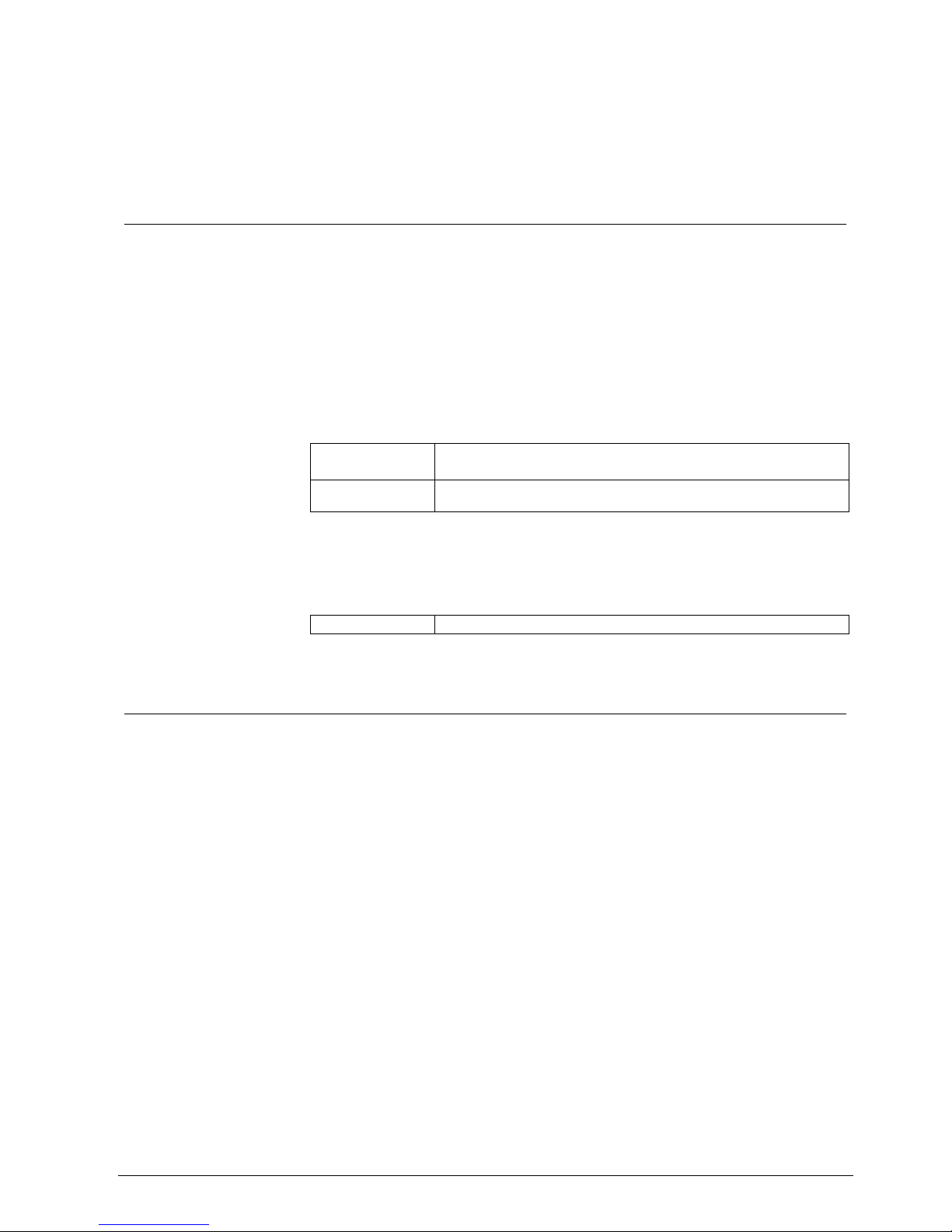
2.3 Meaning of the signal words
The severity of a hazard is indicated by the following signal words. Ignoring these
hazards may lead to the consequences indicated.
Signal word Type of hazard
WARNING Possible danger of death or severe bodily harm.
CAUTION Danger of minor bodily injury or property damage
IMPORTANT Danger of malfunctions
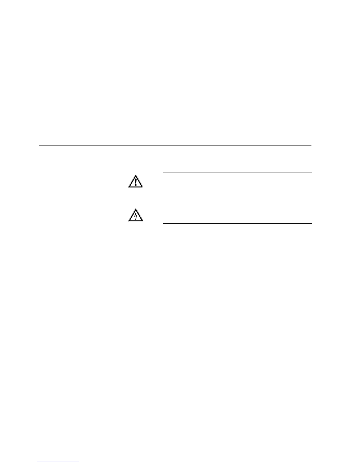
2.4 Meaning of the hazard symbols
The nature of the hazard is indicated by icons.
Dangerous situation
Electrical voltage
9
Siemens Building Technologies
Fire Safety & Security Products 08.2006
3 Guidelines and standards
3.1 EU directives
The product meets the requirements of the EU Directive 89/336/EEC on
electromagnetic compatibility The EU declaration of conformity is available from:
Siemens Building Technologies
Fire & Security Products GmbH & Co. oHG
76181 Karlsruhe, Germany
EU Directive 89/336/EEC on electromagnetic compatibility
Conformity with the European Directive 89/336/EEC is demonstrated by
compliance with the following standards:
Emitted interference: EN 61000-6-3
EN 55022 Class B
Resistance to
interference:
EN 50130-4
EU Directive 73/23/EEC „Low-Voltage Directive”
Compliance with the European Directive 73/23/EEC has been proven by testing
according to the following standard:
Safety: EN 60950-1
3.2 FCC compliance
This equipment has been tested and found to comply with the limits for a Class A
digital device, pursuant to Part 15 of the FCC Rules. These limits are designed to
provide reasonable protection against harmful interference when the equipment is
operated in a commercial environment.
This equipment generates, uses, and can radiate radio frequency energy and, if
not installed and used in accordance with the instruction manual, may cause
harmful interference to radio communications.
Operation of this equipment in a residential area is likely to cause harmful
interference and the user may be required to correct this. Shielded cables should
be used with this unit to ensure compliance with class A limits.

10
Siemens Building Technologies
Fire Safety & Security Products 08.2006
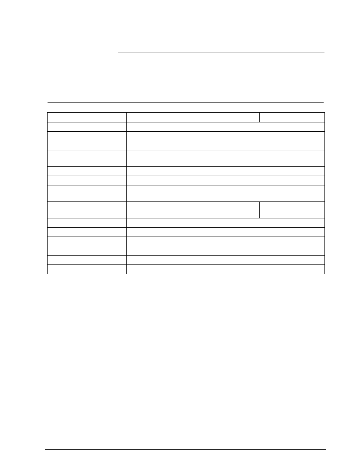
4 Technical data
4.1 Dome
Electrical
Camera types 18x optical Colour (PAL): CCDS1415-ST
18x optical Day/Night (PAL): CCDS1415-DN
26x optical Day/Night (PAL): CCDS1415-DNX
Input voltage XTU 110 – 230 V AC @ 50 / 60 Hz, 1 A max.
In-rush current XTU 40 A / 20 A peak @ 110 / 230 V AC
Input voltage Dome unit 18-24 V DC @ 2 amp, supplied from the XTU via the
Cat-5 cable
Connections Video: BNC coax
Power: Screw terminal block
Telemetry: C type(Coax): BNC
D type (Twisted Pair): Screw terminal block
Alarm: Screw terminal block
Relay: Screw terminal block
Photon: Screw terminal block
Electromagnetic
compatibility
Compliant with EMC directive 89/336/EC.
Conforms to Part 15 of the FCC Rules, Class A digital
device
Operational
Pan speed 0.2-360°/sec
Pan travel 360° continuous
Tilt speed 0.2-360°/sec
Tilt travel +10° and -100°
Presets 99
Tours 32 positions, fully programmable for sequence, dwell and
speed
Preset accuracy 0.3°
Control hardware SIMATRIX NEO, SIMATRIX SYS/648/164 via CAC0103,
CKA3210, CKA4820, SISTORE AX, CX, MX, SX,
Visilynx V3i, Visilynx II, Visilynx 2+, 6000 series, 600
series,
XTU video output Nominal (no gain) VBS 1.0 Vp-p (sync negative)
Relay contact rating 1.5 A @ 24 V DC
Alarm input Opto-coupled (short to alarm com.)
Mechanical
Application Indoor or outdoor - all models
Mounting Wall/fixed ceiling, corner, wall top, pendant, pole, swan
neck or ceiling tile
Pendant mount size/thread Standard 1.5” BSP (parallel)
Weight Boxed 5.6 kg, XTU only (no cables) 1.5 kg, DOME UNIT
only (no cables) 2.5 kg
Ext. construction Injection moulded polycarbonate (GE Lexan EXL9335)
Colour Pure white RAL9010
Bubble Smoked: CCDS1415-ST
Clear:CCDS1415-DN / -DNX
11
Siemens Building Technologies
Fire Safety & Security Products 08.2006
Environmental
IP 67
Operating temperature -10 to +40 °C (-20°C after unit has been powered up for
3 hours)
Storage temperature -20 to +60 °C
MTBF 50,000 hrs (electric parts)
All specifications are subject to change without prior notice.
4.2 Camera module
CCDS1415-DNX CCDS1415-DN CCDS1415-ST
Image sensor
1/4” type IT CCD (EX View HAD)
Effective pixels PAL
430k
Resolution PAL
480 TV lines
Lens
26 x zoom 3.5 mm to
91 mm (F1.6 to F3.8)
18 x zoom 4.1 mm to 73.8 mm
(F1.4 to F3.0)
Digital zoom
12 x
Angle of view
2.2° (tele) to 54.2° (wide) 2.7° (tele) to 48° (wide)
Minimum object distance
320 mm (wide end),
1500 mm (tele end)
290 mm (wide end),
800 mm (tele end)
Minimum illumination
0.05 lux (colour)
0.01 lux (mono)
0.05 lux (colour)
S/N ratio
>50 dB
Electronic shutter
1/10000 s, 22 steps 1/1 to 10000 s, 22 steps
White balance
Auto/One Push
Gain
Auto (-3 to 28 dB, 2 dB steps)
Focusing system
Manual/automatic
Privacy zones
24

12
Siemens Building Technologies
Fire Safety & Security Products 08.2006
5 Ordering information
Type Part. No. Designation
CCDS1415-DNX 2GF1194-8AD ¼" high-resolution Dome, 24 privacy zones, x26 zoom, colour/mono, clear
bubble, IP67, supplied with 110 – 230 V AC XTU
CCDS1415-DN 2GF1194-8AC ¼" high-resolution Dome, 24 privacy zones, x18 zoom, colour/mono, clear
bubble, IP67, supplied with 110 – 230 V AC XTU
CCDS1415-ST 2GF1194-8AA ¼" high-resolution Dome, 24 privacy zones, x18 zoom, colour, smoked
bubble, IP67, supplied with 110 – 230 V AC XTU
CCDS1415-DH 2GF1194-8BA Dummy Dome, IP67 (no camera or XTU)
CCDS1415-CH 2GF1194-8BB Dome Housing for box camera, IP67 (no camera or XTU)
Accessories, not included in the delivery!
CCDS1415-PM 2GF1194-8CA Pendant mount
CCDS1415-FM 2GF1194-8CB Recessed ceiling tile mount
CCDS1415-SN 2GF1194-8CC Swan neck bracket
CCDS1415-WM 2GF1194-8CD Wall /ceiling mount
CCDS1415-CMA 2GF1194-8CE Corner mount adapter
CCDS1415-BM 2GF1194-8CF Parapet mount adapter
CCDS1415-RTU 2GF1194-8CG Remote Termination Unit (RTU)
Spare parts
CCDS1415-XTU 2GF1194-8BC External Termination Unit (XTU)
CCDS1415-BC 2GF1194-8BD Clear bubble
CCDS1415-BS 2GF1194-8BE Smoked bubble

13
Siemens Building Technologies
Fire Safety & Security Products 08.2006
6 Scope of delivery
Prior to installation confirm that the following are in the box:
z 1 x Solaris™ Dome unit
z 1 x External Termination Unit (XTU)
z 1 x Dome connection cable (Cat 5) with weatherproof connector
z 1 x installation manual
z 1 x cable gland pack (for XTU)
z 4 x cable ties (for XTU cable management)
z 5 mm AF Allen key
z 1.5” BSP knurled locking nut
z 2 x extra cable ties for connection cable
z Printed mounting instructions
z CD containing detailed configuration manuals
14
Siemens Building Technologies
Fire Safety & Security Products 08.2006
7 Unit description
A complete Solaris™ Dome system consists of a single sealed Dome unit
(containing a camera fitted to a pan and tilt mechanism), connected by a Cat-5
cable to an External Termination Unit (XTU). The XTU contains a PSU and a PCB
fitted with a variety of interface connection terminals.
The installation of a Solaris™ Dome consists of two parts:
z the installation of the Dome unit and
z the installation of the XTU.
The following chapter is concerned with the first of these. It will take you step by
step through the various types of installation.
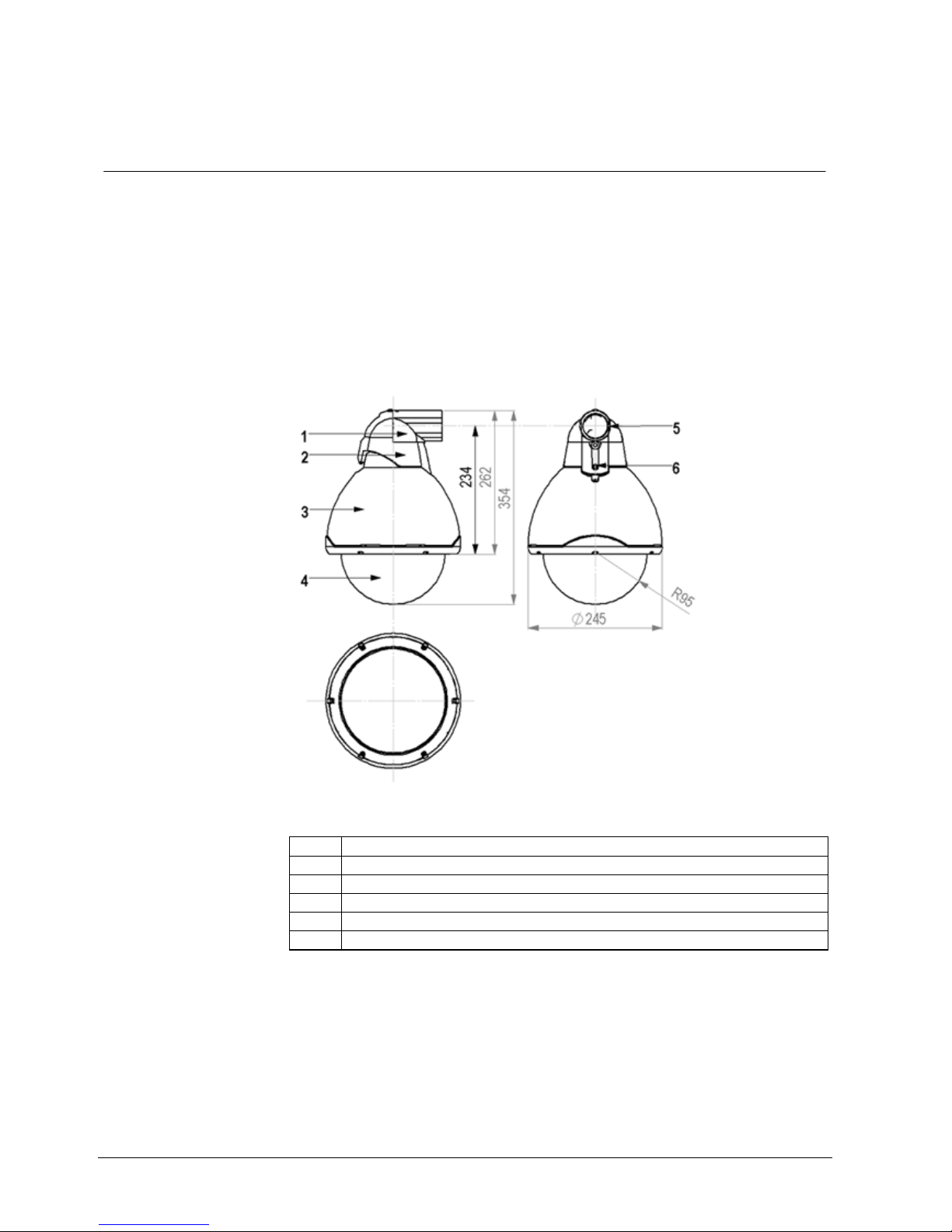
Fig. 1 Parts of the Solaris™ Dome
1 Mounting bracket (fixed horizontally or vertically)
2 Hinged bracket assembly
3 Dome
4 Bubble
5 1.5" BSP mounting thread
6 Screw for hinge assembly

15
Siemens Building Technologies
Fire Safety & Security Products 08.2006
8 Installation of the Dome unit
Before commencing use of the Solaris™ system, ensure the following has been
completed:
1. Ensure you have the correct tools to complete the installation, (see Section
8.1: Tools required).
2. Install the desired bracket in a suitable location, (see Sections 8.3.1 to 8.3.6).
3. Prepare the Dome bracket and attach it to the appropriate mounting bracket,
(see Sections 8.4: Preparing the Dome bracket and 0: Mounting the Dome
bracket to a wall mount ).
4. Assemble the Cat5 cable (see Section 8.5: Cat5 cable assembly and
disassembly).
5. Hook the Dome on to the hinge mechanism and connect the cable, clipping it
in place (ensure that it is correctly and firmly seated on the connector). Pull
the Dome into the vertical position (see Section 8.6: Connecting the Solaris™
Dome).
6. Check the bubble and ensure there are no scratches on the surface. If the
surface is marked, it may impair optical clarity.
7. Select a suitable location and mount the XTU, (see Sections 9.2.1: Choosing
a location for the XTU and 9.2.2: Mounting the XTU).
8. Connect the XTU to any external equipment, (see Section 9.3: Connecting the
XTU to external equipment).
9. If necessary, adjust the orientation of the XTU’s LCD display, (see Section
10.2: LCD orientation).
10. Configure the XTU to use the correct telemetry protocol and to identify itself
correctly, (see Section 10.3: The XTU main menu).
11. Setup the controller, (see Section 12: Telemetry controller operation and
setup and the controller’s installation and commissioning manual).
8.1 Tools required
Installing the Dome unit and the External Termination Unit requires only a basic
tool kit, including:
z 3 mm AF Allen key (supplied with ceiling mounting kit)
z Medium sized Pozidrive screwdriver
z Terminal screwdriver (flat-bladed)
z RJ-45 crimping tool (only if custom Dome to XTU cable is used)
z Suitable tools for chosen fasteners for fitting bracketry and mounting the XTU
z Suitable tools to install the required cabling and connections
CAUTION
Handle the bubble of the Solaris™ Dome with extreme care and be sure not to
scratch it, as this may affect its optical clarity. If it is accidentally marked it may
be possible to remove small scratches or scuffs on the outer surface with the
use of a suitable cloth and metal polish (brass cleaner). However, if this is not
effective the bubble must be replaced.
16
Siemens Building Technologies
Fire Safety & Security Products 08.2006
8.2 Installation procedure
The two-piece mounting bracket and the hinge mechanism built into the Dome
casing make the physical installation very simple.
Making the electrical connections is just as simple. All of these are provided via a
single connector fitted to the Cat-5 cable supplied.
This just needs to be plugged in and clipped in place before the Dome casing is
closed and fixed with a single screw. This combination ensures quick installation of
the Dome.
Installation using the recessed ceiling tile mount utilises a simplified fixing
procedure compared to other Domes and the electrical connections are just as
simple as with the bracket and pendant mounted units.
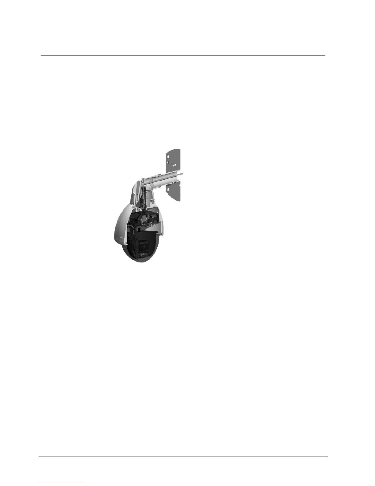
Fig. 2 Cross-sectional view of the Solaris™ Dome
To install the dome unit, proceed as follows:
1. First install the appropriate mounting bracket. See Section 8.3: Installing the
mounting brackets.
2. Prepare the Dome bracket. See Section 8.4: Preparing the Dome bracket.
3. Route the cable through the Dome bracket. See Section 8.5: Cat5 cable
assembly and disassembly.
4. Connect the cable to the Dome unit. See Section 18.6: Connecting the
Solaris™ Dome.
5. Attach the Dome to the Dome bracket.
17
Siemens Building Technologies
Fire Safety & Security Products 08.2006
8.3 Installing the mounting brackets
There are several types of brackets to choose from – wall/ceiling mount, corner
mount adapter, parapet mount adapter, pendant mount, swan-neck bracket and
recessed ceiling tile mount.
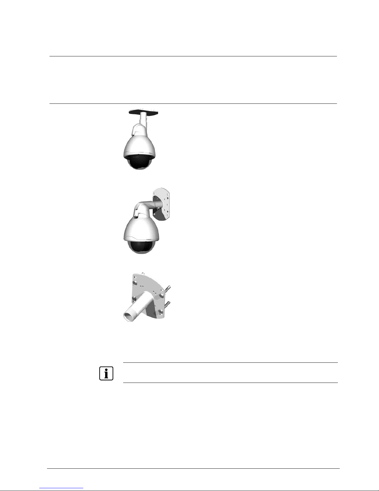
8.3.1 Wall/Ceiling mount CCDS1415-WM
Fig. 3 Ceiling mount
Fig. 4 Wall mount
Fig. 5 Wall / ceiling mount
1. Bolt the wall/ceiling mount to the mounting substrate using the four mounting
holes shown.
NOTE
Ensure the chosen fasteners and fastening method are suitable for the application and the mounting
substrate.
18
Siemens Building Technologies
Fire Safety & Security Products 08.2006
Cable exits
1 Rear of plate
1 M25 electrical conduit threaded cable
exit on the underside of the bracket
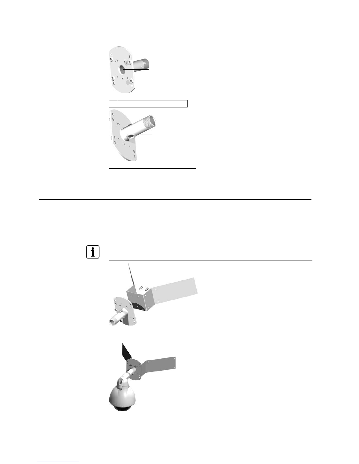
8.3.2 Corner mount adapter CCDS1415-CMA
1. Using 3 x M8 nuts and M8 x 20 bolts fasten the wall mount bracket to the
corner mount adapter as shown below.
2. Fasten the corner mount adapter to the mounting substrate using the eight
holes shown.
NOTE
Ensure the chosen fasteners and fastening method are suitable for the application and the mounting
substrate.
Fig. 6 Wall bracket in conjunction with corner mount adapter
Fig. 7 Solaris™ Dome mounted to wall bracket and corner mount adapter
1
1

19
Siemens Building Technologies
Fire Safety & Security Products 08.2006
8.3.3 Parapet mount adapter CCDS1415-BM
1. Fasten the wall mount to the parapet mount adapter using the four M8 bolts
supplied with CCDS1415-BM (see below).
2. Fasten the parapet mount adapter to the mounting substrate using the four
holes shown.
NOTE
Ensure the chosen fasteners and fastening method are suitable for the application and the mounting
substrate.
Fig. 8 Wall bracket in conjunction with parapet mount adapter
Fig. 9 Solaris™ Dome mounted to wall bracket and parapet mount adapter

20
Siemens Building Technologies
Fire Safety & Security Products 08.2006
8.3.4 Pendant mount CCDS1415-PM
The pendant mount CCDS1415-PM is supplied with a 1.2 m pole.
1. Cut the unthreaded end of the pole to the desired length.
2. Slide the pole into the top of the mounting flange until level with the top face of
the flange.
3. Spot drill the pole through the holes in the mounting flange.
4. Remove the pole and drill through both sides of the pole with a 9 mm drill.
5. Re-insert the pole and secure it using two M8 x 60 screws provided with the
pendant mount.
6. Fasten the mounting flange to the mounting substrate using the three holes
shown.
NOTE
Ensure the chosen fasteners and fastening method are suitable for the application and the mounting
substrate.
Fig. 10 Pendant mount
21
Siemens Building Technologies
Fire Safety & Security Products 08.2006
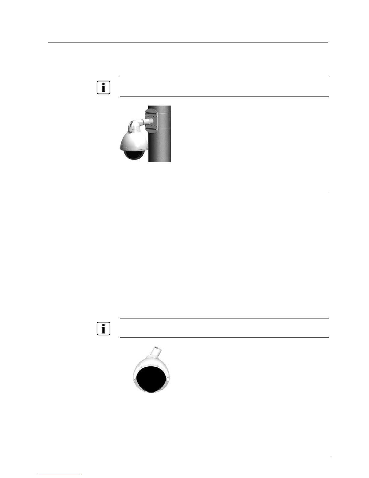
8.3.5 Pole fixture (using wall mount CCDS1415-WM)
The wall mount CCDS1415-WM has four 12 mm square holes through the
mounting plate. These holes are to pass 11 mm continuous banding through as
shown.
NOTE
Ensure the chosen fasteners and fastening method are suitable for the application and the mounting
substrate.
Fig. 11 Pole mounting
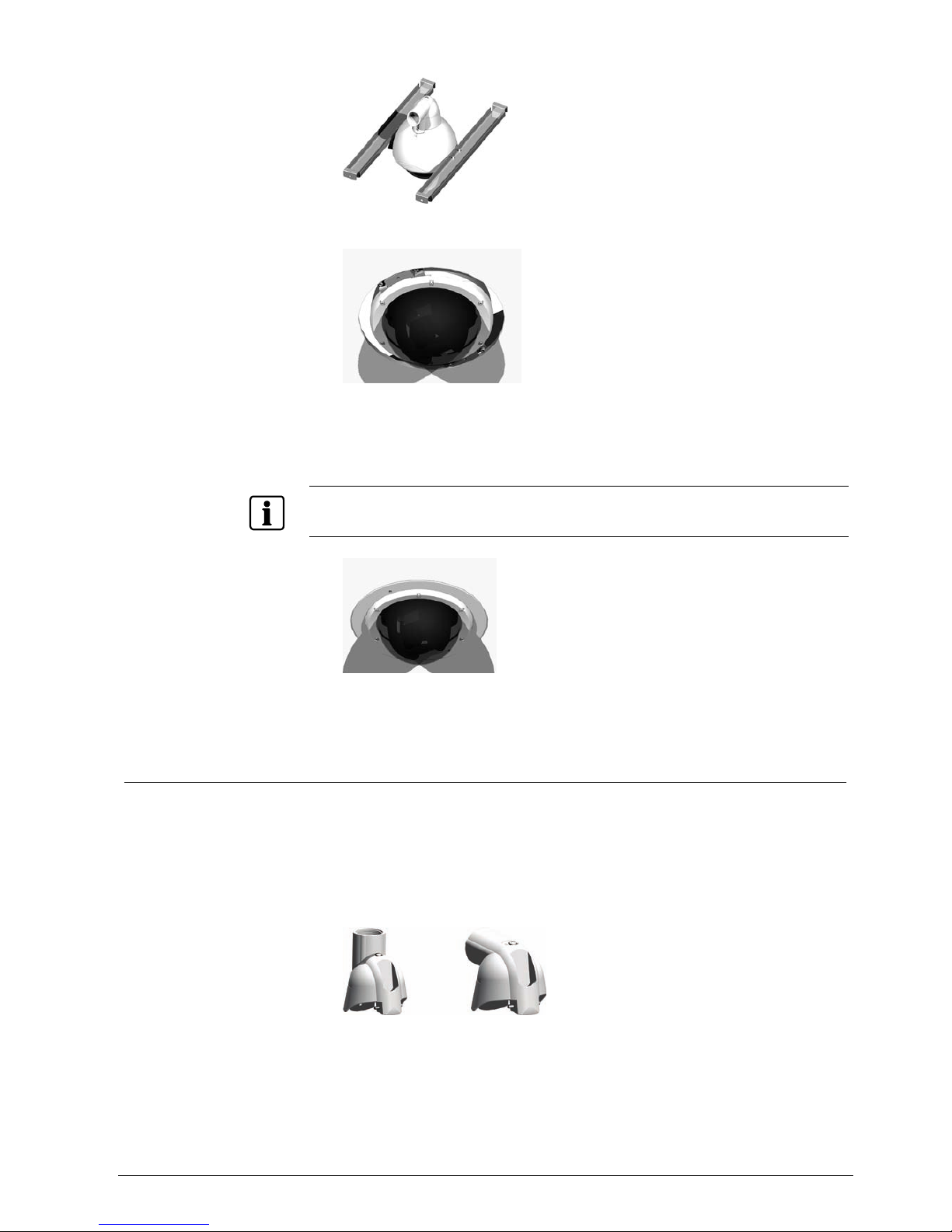
8.3.6 Recessed ceiling tile mount CCDS1415-FM
The Solaris™ Dome can be installed in a standard false ceiling tile using the
recessed ceiling tile mount. The recessed ceiling tile mount consists of two
accessory mounting brackets that are fixed to the Solaris™ Dome, and two Uchannel brace bars which are secured to the ceiling support framework. The brace
bars are suitable for use with both 600x600 mm and 600x1200 mm ceiling tile
systems.
To install the recessed ceiling tile mount you will need access to the top of the tile
from one or more adjacent tiles.
Install using the recessed ceiling tile mount as follows:
1. Prepare the ceiling tile by cutting a 235 mm diameter hole in the centre (using
the template provided) and then fit it back in place in the ceiling support
frame.
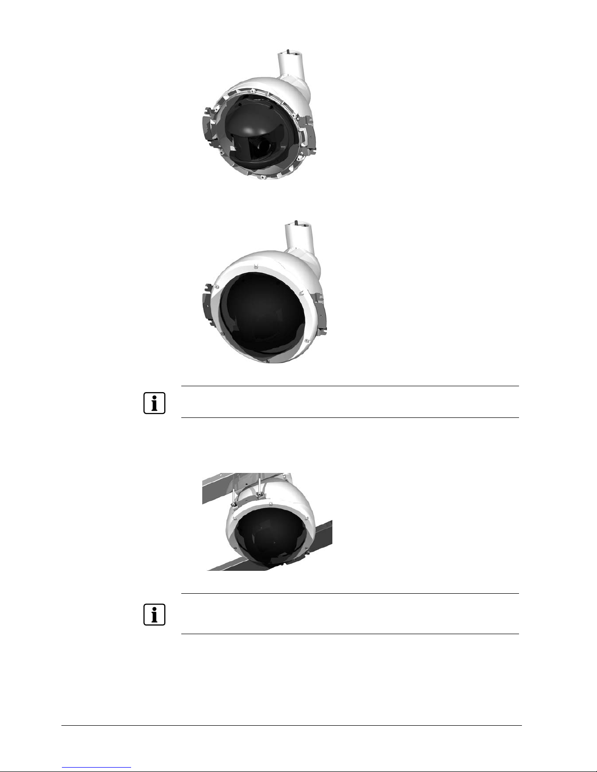
2. Remove the six screws holding the Solaris™ Dome's bezel in place and
remove the bezel.
NOTE
Handle the bubble of the Solaris™ Dome with extreme care and be sure not to scratch it, as this may
affect its optical clarity.
3. Fit the ceiling mount accessory brackets in place using the four self-tapping
screws provided.
22
Siemens Building Technologies
Fire Safety & Security Products 08.2006
4. Refit the bezel; tighten the six screws lightly to begin with, and then fully
tighten each in turn.
NOTE
Ensure that the six screws are sufficiently tight to compress the bubble seal (recommended torque
setting 1.2 - 1.3 Nm).
5. Fit the brace bars to the accessory brackets using the support screws
provided.
NOTE
The recessed ceiling tile mount is for use with standard thickness ceiling tiles. If using non-standard
thickness ceiling tiles, it may be necessary to use different support screws (not supplied) to mount the
brace bars onto the accessory brackets.
23
Siemens Building Technologies
Fire Safety & Security Products 08.2006
6. Lower the complete assembly into place, allowing the Dome to pass through
the hole in the ceiling tile.
7. Ensure that the brace bar is correctly located on the support framework and
then fix it using the screws provided.
8. Fit the supplied bezel.
NOTE
The Dome can be lowered or raised depending on the situation by adjusting the height of the support
screws.
9. Connect the cable connector to the socket.
Î The ceiling tile installation is now complete.
8.4 Preparing the Dome bracket
The Dome bracket is provided with a standard 1.5" BSP thread and stainless steel
lock nut to enable it to be used with a range of standard mounting hardware. The
bracket is constructed of two parts, which can be turned in respect of each other to
allow for a vertical or horizontal mounting arrangement.
To prepare the bracket for mounting the Dome:
1. Orientate the two parts of the bracket correctly.
 Loading...