

Siemens SL45 Service Manual
Information and Communication Mobile
Mobile Phones
SL45/6688
Level 2.5
Repair Documentation
V 1.2
V1.2 Page 1 of 31 ICM MP CC ST
M. Klapheck / D. Schnoor
03/01
Information and Communication Mobile
Mobile Phones
Table of Contents:
1 INTRODUCTION .......................................................................................................................................... 3
2 BOTTOM CONNECTOR (LUMBERG) ..................................................................................................... 4
3 DISPLAY CONNECTOR ............................................................................................................................. 8
4 KEYBOARD LEDS ..................................................................................................................................... 12
5 KEYBOARD CONNECTOR ...................................................................................................................... 15
6 IRDA DIODE ............................................................................................................................................... 19
7 ANTENNA CONNECTOR ......................................................................................................................... 22
8 RESISTOR R384 ................................................................................................ .......................................... 26
9 VOLTAGE PROTECTION DIODE V200 ................................................................................................ 30
V1.2 Page 2 of 31 ICM MP CC ST
M. Klapheck / D. Schnoor
03/01
Information and Communication Mobile
Mobile Phones
1 Introduction
SL45 product family, internally referred to as U35, consists of 2 different dualband handsets
(GSM-900 and GSM-1800), which can easily be distinguished from the second block of the
partnumber printed on the IMEI label. There is a standard type SL45 and a Chinese type
called 6688.
Partnumber on IMEI label:
1) SL45: S30880-S4800-#1xx
2) 6688: S30880-S4800-#8xx
,while # may be any letter (A-Z) and xx may be any number from 10,20,30 ....90.
Important:
The SL45 and the 6688 use a different hardware (RF/control module). This is due to
the fact that for the Chinese type there is a bigger flash memory size required for the
Chinese characters.
The information in this manual applies to both types, SL45 and 6688, unless otherwise
noted.
This manual is intended to help you carry out repairs on level 2.5, meaning limited
component repairs. Failure highlights are documented and should be repaired in the local
workshops.
It must be noted that all repairs have to be carried out in an environment set up according to
the ESD (Electrostatic Discharge Sensitive Devices) regulations defined in international
standards.
If you have any questions regarding the repair procedures or spare parts do not hesitate to
contact our technical support team in Kamp-Lintfort, Germany:
Tel.: +49 2842 95 4666
Fax: +49 2842 95 4302
e-mail: dominik.schnoor@klf.siemens.
V1.2 Page 3 of 31 ICM MP CC ST
M. Klapheck / D. Schnoor
03/01

Information and Communication Mobile
Mobile Phones
2 Bottom Connector (Lumberg)
2.1 Affected Units
2.1.1 Type: SL45/6688
2.1.2 Affected IMEIs / Date Codes: All / All
2.1.3 Affected SW-Versions: All
2.1.4 Fault Code for LSO reporting: 3LUC
2.2 Fault Description
2.2.1 Fault Symptoms for customers:
Charging problems.
Problems with external loudspeaker or microphone
when using a car kit.
Problems with accessories connected at the bottom
connector.
Problems with SW booting.
2.2.2 Fault Symptom on GSM-Tester:
This problem cannot be detected with a GSM-Tester.
2.3 Priority:
........ Mandatory
........ Repair
........ Optional
........ Not Yet Defined
V1.2 Page 4 of 31 ICM MP CC ST
M. Klapheck / D. Schnoor
03/01

Information and Communication Mobile
Mobile Phones
2.4 Repair Documentation
2.4.1 Description of procedure:
2.4.1.1 Diagnosis
Visually check the bottom connector. Watch for dry joints!
2.4.1.2 Repair by component change
Use hot air blower remove defective bottom connector.
Avoid excessive heat!
Watch surrounding components!
Resolder new bottom connector afterwards.
2.4.1.3 Repair by SW-Booting
Not possible!
2.4.1.4 Test
Retest handset after repair.
2.4.2 List of needed material
2.4.2.1 Components
Bottom Connector SL45/6688
Part-Number: L36334-Z93-C262
2.4.2.2 Jigs and Tools
Hot Air Blower
Soldering Iron
2.4.2.3 Special Tools
None
V1.2 Page 5 of 31 ICM MP CC ST
M. Klapheck / D. Schnoor
03/01
Information and Communication Mobile
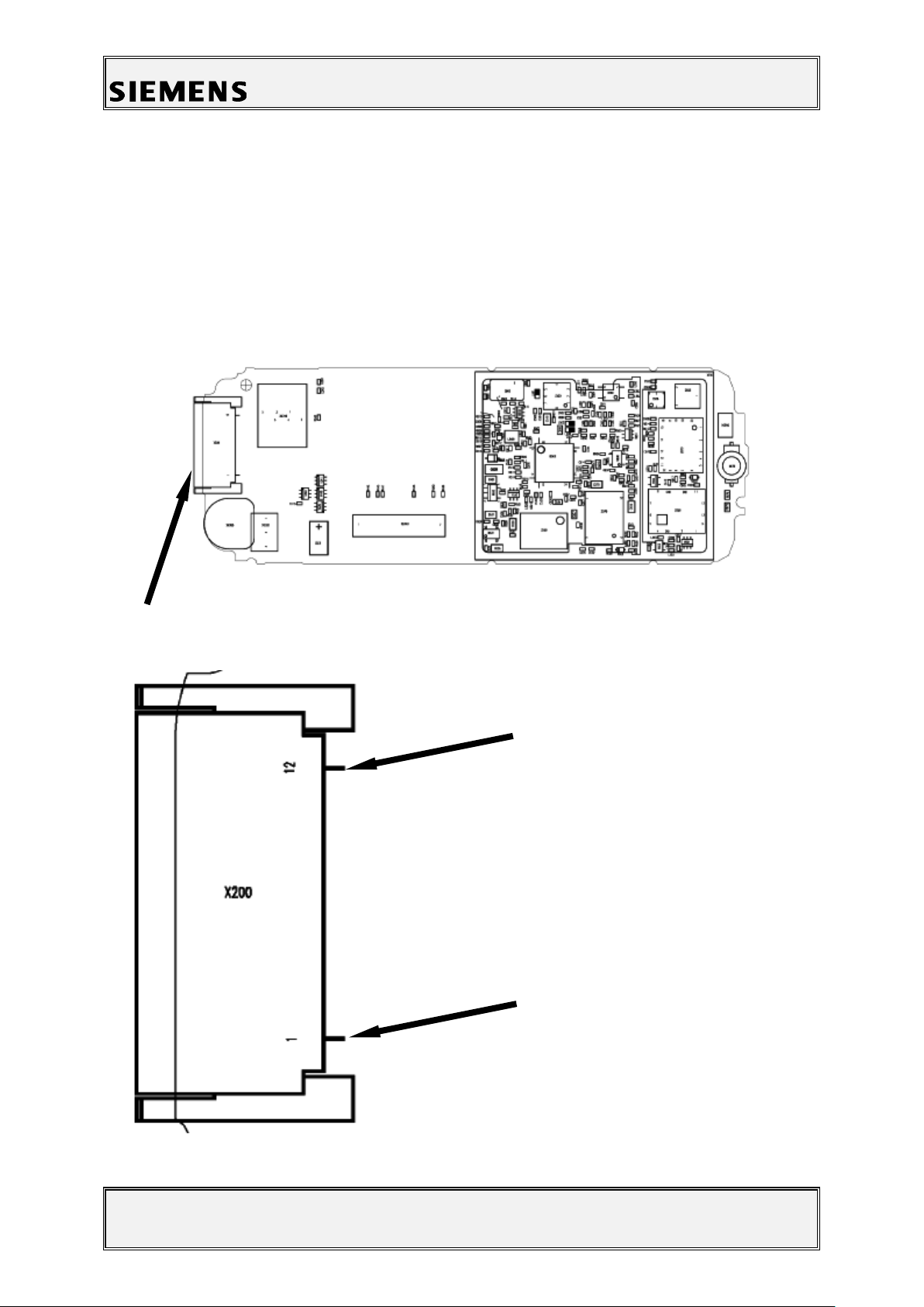
Figure 1: SL45/6688 Board Bottom Connector Side
Figure 2: SL45/6688 Bottom Connector Placement (Top View)
Pin 12
Pin 1
Mobile Phones
2.4.2.4 Working materials
Desolder Wick / Braid
Solder
2.4.3 Drawings
V1.2 Page 6 of 31 ICM MP CC ST
M. Klapheck / D. Schnoor
03/01
Information and Communication Mobile
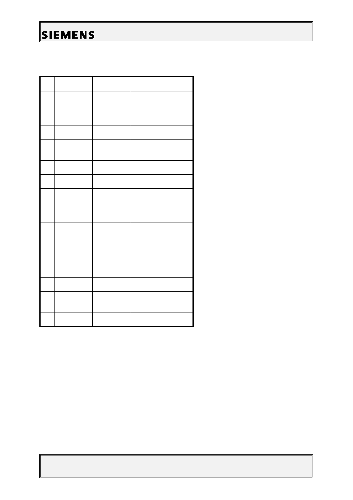
Pin
Name
IN/OUT
Notes
1
GND
2
HS_LEFT
I/O
Output left channel for
stereo-headset.
3
POWER
I
Charging Current
4
FBatt+
O
Power supply for the
accessories.
5
TX O Serial interface
6
RX I Serial interface
7
ZUB_CLK
I/O
Clock line for
accessory bus
Use as DTC In data
operation
8
ZUB_DATA
I/O
Data line for
accessory bus.
Use as CTS in data
operation
9
GND_MIC
For external
microphone
10
MICP2
I
External microphone
11
HS_RIGHT
O
Output right channel
for stereo-headset
12
LGND
For external
loudspeaker
Table 1: SL45/6688 Bottom Connector Pin Description
Mobile Phones
V1.2 Page 7 of 31 ICM MP CC ST
M. Klapheck / D. Schnoor
03/01

Information and Communication Mobile
Mobile Phones
3 Display Connector
3.1 Affected Units
3.1.1 Type: SL45/6688
3.1.2 Affected IMEIs / Date Codes: All / All
3.1.3 Affected SW-Versions: All
3.1.4 Fault Code for LSO reporting: 3DIC
3.2 Fault Description
3.2.1 Fault Symptoms for customers:
Display problems, like missing lines or columns on the
LCD or display contrast problems.
3.2.2 Fault Symptom on GSM-Tester:
Display test fails.
3.3 Priority:
........ Mandatory
........ Repair
........ Optional
........ Not Yet Defined
V1.2 Page 8 of 31 ICM MP CC ST
M. Klapheck / D. Schnoor
03/01
Information and Communication Mobile
Mobile Phones
3.4 Repair Documentation
3.4.1 Description of procedure:
3.4.1.1 Diagnosis
Visually check the status of the display connector. Watch for oxidation
and dry solder joints.
Mechanically check the opening / closing mechanism.
3.4.1.2 Repair by component change
Use hot air to remove defective connector
Avoid excessive heat!
Watch surrounding components!!
Resolder new connector afterwards
3.4.1.3 Repair by SW-Booting
Not possible!
3.4.1.4 Test
Retest handset after repair.
V1.2 Page 9 of 31 ICM MP CC ST
M. Klapheck / D. Schnoor
03/01

Information and Communication Mobile
Mobile Phones
3.4.2 List of needed material
3.4.2.1 Components Display connector SL45/6688:
Part-Number: L36334-Z97-C130
3.4.2.2 Jigs and Tools
Soldering Iron
Hot Air Blower
3.4.2.3 Special Tools
None
3.4.2.4 Working materials
Desolder Wick / Braid
Solder
V1.2 Page 10 of 31 ICM MP CC ST
M. Klapheck / D. Schnoor
03/01
 Loading...