

Siemens SKP Series, SKP70.110U17, SKP70.111U17, SKP70.192U17, SKP70.191U17 Technical Instructions
...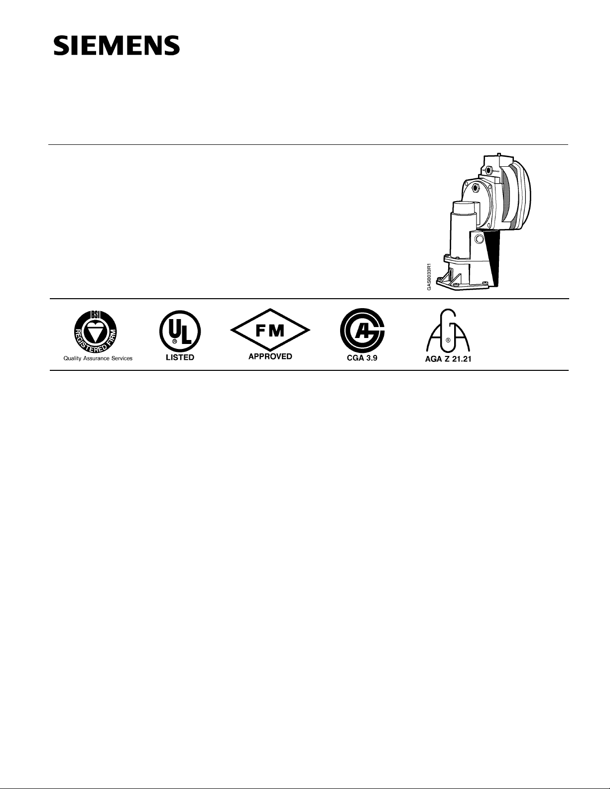
SKP Series
SKP70…U.. Air/Gas Ratio Controlling Actuators
With Safety Shutoff Function—
For Use With Gas Valves VG…
Te
Tecccchhhhnnnniiiiccccaaaal I
TeTe
l Innnnssssttttrrrruuuuccccttttiiiion
l Il I
onssss
onon
Document No. 155-516P25
SKP70…U..
Rev. 2, December, 1998
DDDDes
esccccrrrriiiippppttttiiiioooonnnn
eses
SKP70… pressure regulating electro-hydraulic actuators are used in combination with
VG… series gas valves to provide slow opening fast closing shutoff and air/gas ratio
control for industrial and commercial burner applications.
The SKP70… controls the burner manifold gas pressure as a function of the
combustion air pressure without the need for an additional constant gas pressure
regulator.
Since three functions, safety shutoff, constant pressure regulation and air/gas ratio
control can be performed by a single valve, fewer components and fittings are required
to assemble a gas train reducing both the size and the weight of the gas train
significantly. The total pressure drop across the gas train arrangement is reduced,
allowing for the use of smaller diameter gas trains in most applications.
The modular design allows the SKP70… to be used in combination with all VG… series
gas valves from ½-inch to 5-inch in size. The actuator is easily mounted on the square
flange of any VG… valve by means of four bolts contained in the terminal box of the
actuator. No gaskets or seals are required when mounting the actuator. The valve
position is shown by a visible position indicator displaying the entire stroke range of the
actuator.
Siemens Building Technologies, Inc.
Landis Division
Technical Instructions
Document No. 155-516P25
Rev. 2, December, 1998
FFFFeeeeaaaattttur
ures
es
urur
eses
AAAApp
ppli
liccccaaaattttiiiioooonnnn
pppp
lili
UL listed, FM approved, CGA and AGA certified, IRI approvable, ISO 9001 certified;
x
European, Australian and Japanese approved versions available.
Safety shutoff function, pressure regulating function and air/gas ratio control in one
x
compact unit.
Simplifies commissioning and reduces startup time.
x
Maintains air/gas ratio when the air flow is disrupted.
x
Automatic compensation for combustion chamber back pressure fluctuations.
x
No mechanical wear or play that causes drifting.
x
Compensation for air temperature fluctuations.
x
Visual stroke position indicator.
x
Can be mounted in any location.
x
Optional auxiliary switches available.
x
Excellent tracking characteristics
x
SKP70… series actuators can be combined with ½-inch to 5-inch VG… series gas valve
bodies. VG… series gas valves are ordered as separate items (
Instruction No. 155-512P25).
VG…U.. Technical
See
PPPPrrrroooodu
ducccct
dudu
t NNNNuuuummmmbbbbeeeerrrrssss
t t
If the combustion air pressure exceeds the permissible value of 12” or 20” w.c. (
Specifications), the pressure must be reduced by means of a pressure reducing Tfitting (
A motorized pressure reducing control (SQN37… ) can also be installed in the air
impulse line to continuously optimize combustion when used in conjunction with an
oxygen trim system.
Figure 4, AGA78).
See
TTTTaaaabbbblllle
e 1111.
. PPPPrrrroooodddduuuucccct
e e
. .
OOOOrrrrddddeeeer
r NNNNuuuummmmbbbbeeeerrrrO
r r
SKP70.110U17 110-120 Vac No —
SKP70.111U17 110-120 Vac Auxiliary SPDT
SKP70.191U17 110-120 Vac Proof of Closure SPST
SKP70.192U17 110-120 Vac
SKP70.110U27 220-240 Vac No —
SKP70.111U27 220-240 Vac Auxiliary SPDT
SKP70.192U27 220-240 Vac
AGA78
OOOppppeeeerrrraaaattttiii
ing
ng
ngng
VVVVoooollllttttaaaage
ge
gege
Air pressure reducing T-fitting
t NNNNuuuummmmbbbbeeeerrrrssss
t t
PPPPrrrroo
oof
f oooof
f CCCClllloooossssuuuurrrreeee
oooo
f f
f f
&
& AAAAuuuuxxxxiiiilllliiiiaaaarrrry
& &
Proof of Closure
Proof of Closure
y SSSSwwwwiiiittttcccchhhh
y y
& Auxiliary
& Auxiliary
TTTTyyyyppppe o
SSSSwwwwiiiittttcccchhhh
SPST
SPST
SPST
SPST
e offff
e oe o
See
IIIInnnnssssttttaaaall
PPPPaaaage
ge 2222 oooof
ge ge
llaaaattttiiiioooon
n CCCCoooonnnnvvvveeeennnnttttiiiioooonnnn
llll
n n
WARNING:
f 9999 Siemens Building Technologies, Inc.
f f
Personal injury/loss of life may occur if a
procedure is not performed as specified.
Landis Division

SKP70…U.. Air/Gas Ratio Controlling Actuators Technical Instructions
155-516P25
Rev. 2, December, 1998
SSSSppppeeeecccciiiiffffiiiiccccaaaattttiiiioooonnnnssss
Agency approvals
Power supply
Operating environment
Physical characteristics
Connections
Operating characteristics
Control signal
Operation/installation
Auxiliary features
As safety shut-off valve UL/429, FM/7400, CGA/3.9,
AGA/Z 21.21 in combination with
VG…U.. series gas valves
UL recognized when used with other valves.
Operating voltage 110 to 120 Vac + 10%-15%
220 to 240 Vac + 10%-15%
Operating frequency 50 to 60 Hz + 6%
Power consumption 20 VA
Duty cycle 100%
o
Ambient operating temperature 15
to 140oF (-10o to 60o C)
Mounting position Optional, with diaphragms in vertical
position but not upside down
Maximum temperature of air and flue
gas at the control connections 140
o
F (60oC)
Maximum inlet gas pressure Same as VG… valve
Weight 5.5 lb (2.5 kg)
Enclosure NEMA 1, 2, 5 and 12 for indoor use
Dimensions
Specification for valves
Figure 6
See
gas valve Technical Instruction
See
No. 155-512P25
Conduit connection ½-inch NPSM adapter
Gas/air/combustion chamber pressure
connections ¼” NPT
Output force 100 lb (450 N)
Maximum stroke 0.7” (18 mm)
Opening time for maximum stroke 12 s
Closing time < 0.8 s
Reference input signal Combustion air pressure
Control characteristic integral action
Setting range of gas to air pressure ratio 0.4:1 to 9:1
Permissible pressures
during operation for accurate control Min. air presssure: 0.2” w.c.
Max. air pressure: with Pg/Pa <2; 20” w.c.
Max. air pressure: with Pg/Pa >2; 12” w.c.
with higher air pressures use AGA78
Min. downstream gas pressure: 0.4” w.c.
Max. downstream gas pressure: 40” w.c.
Minimum time required for high to low
fire load changes Approx. 5 s
Permissible leakage test pressure 20 psi
Permissible leakage test vacuum 3 psi
Minimum diameter of impulse pipes ¼” inside diameter (
Installation)
See
Minimum distance between gas
impulse pipe connection and gas
valve outlet 5 x pipe diameter
Capacity of auxiliary switch 6 (3) A, 250 Vac
Setting range of auxiliary switch Full stroke
Siemens Building Technologies, Inc PPPPaaaage
Landis Division
ge 3333 oooof
ge ge
f 9999
f f
 Loading...