

Siemens SKP25.011U1, SKP25.012U1, SKP25.013U1, SKP25.012U2, SKP25.013U2 Technical Instructions
...
Technical Instructions
SKP25U.. Pressure Regulating Gas
SKP Series
Valve Actuator with Safety Shut-off
Function
Document No. 155-752
SKP25U..
July 9, 2014
Description
Features
Only when assembled to Series VGU Gas valves
SKP25 pressure regulating electro-hydraulic actuators combine with VG series gas
valve bodies to provide safety shut-off and gas pressure regulation for industrial and
commercial burners. The SKP25 can also be applied as a 1:1 air/gas proportionator
or zero governor.
Since a single valve performs two or more functions, fewer gas train components and
fittings are required. This significantly reduces both the size and weight of the gas train.
In addition, smaller diameter gas valves can be used.
The compact SKP25 actuator opens slowly and closes immediately when power is
interrupted. The modular design allows the SKP25 to be used in combination with all
VG series gas valve bodies from 1/2-inch to 6-inch in size. The actuator is easily
mounted on the square flange of any VG valve with four pre-mounted screws. A
visible position indicator on the front of the actuator displays the entire stroke of the
valve. A light indicates when the actuator is powered.
• UL listed, FM approved, CSA certified for USA and Canada, and ISO 9001
certified. European, Australian and Japanese approved versions available.
• Certified as a ventless pressure regulator.
• Safety shut-off function and pressure regulating function in one compact unit.
• Proof of Closure with Over Travel (POC) versions.
• Optional NEMA 4 protection.
• Visual position indication.
• "Power on" indication light
• Quick connect wiring terminals
• Optional adjustable auxiliary switch available.
• Applicable as 1:1 air/gas proportionator or zero governor.
• Accurate pressure control characteristics, and zero offset (droop).
• Modular design with 360o actuator rotation for easy field wiring and installation.
• Low, 13.5 VA power consumption.
• Integral regulation leak limiter
Siemens Building Technologies, Inc.
Technical Instructions SKP25U.. Pressure Regulating Gas Valve Actuators
Operating
Proof of Closure
Agency marks apply only for SKPxx.xxxU actuators
Document Number 155-752
July 9, 2014
Application
SKP25 series actuators are combined with 1/2-inch to 6-inch VG series gas valve
bodies. VG series gas valves must be ordered separately (See VGU...Technical
Instructions, P/N 155-512P25).
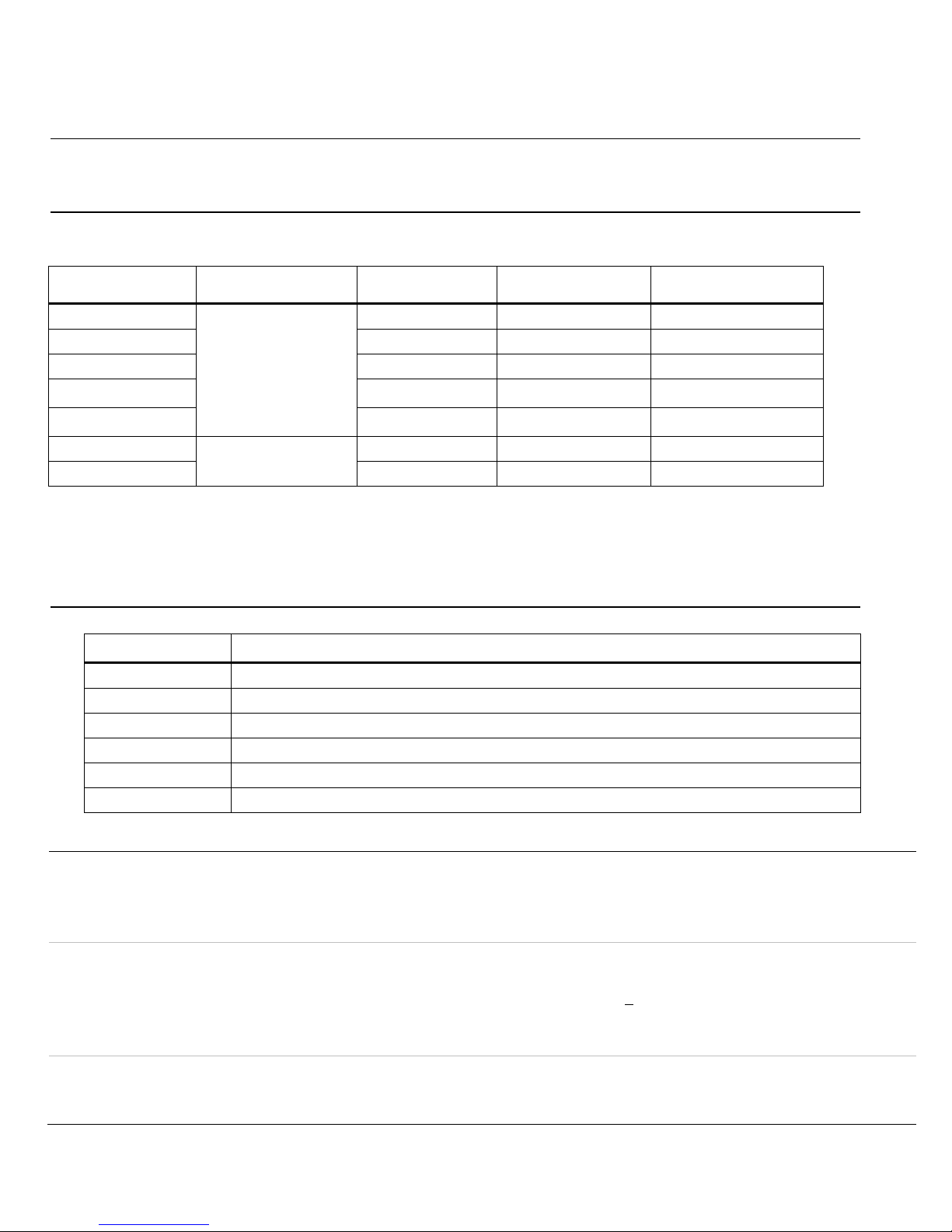
Product Numbers
Table 1.
Product Number1
SKP25.011U1
Voltage
Switch 4
x – SPDT
Auxiliary Switch 4 Type of Switch
SKP25.012U1 x x
SKP25.013U1 – – –
SKP25.411U1 2
SKP25.611U1 3
SKP25.012U2
110 to 120 Vac
220 to 240 Vac
x
x
– SPDT
–
x x
SKP25.013U2 – –
NOTES: 1. European, CE certified models are available (see data sheet 7643)
2. High outlet pressure model for 1.5 to 20 psi outlet pressure regulation
3. High bias model for proportionator function with 0" to – 4" WC bias.
4. Proof of closure and auxiliary switches cannot be field installed
.
Accessories
)
Table 2.
Product Number Description
AGA22
AGA23
AGA25.2
AGA28
AGA29
AGA66
Yellow setpoint spring for 6” to 48” WC (1.5 to 10 psi for SKP25.411U1)
Red setpoint spring for 40” to 100” WC (8.5 to 20 psi for SKP25.411U1)
Damping orifice for mounting into vent connection of SKP25.0 or SKP25.4 models
Black bias spring to install if SKP25.0 is used as proportionator or zero governor
Unpainted setpoint spring for 0” to 8.5” WC (included in SKP25.0 as standard)
Sealing gasket to provide NEMA 3, 3R, and 4 protection (for VGG/VGDvalves)
Specifications
As a safety shut-off valve UL/429, FM/7400, ANSI Z21.21/CSA 6.5 C/I
Agency approvals
assembled with VGxxx.xxxU series gas valve bodies.
As a pressure regulator ANSI Z21.18/CSA 6.3
Power supply Operating voltage 110 to 120 Vac + 10% to -15%
220 to 240 Vac + 10% to -15%
Operating frequency 50 to 60 Hz +6%
Power consumption 13.5 VA
Duty cycle continuous
Operating environment Ambient operating temperature 5°F to 140°F (-15°C to 60°C)
Mounting position Any position except upside down
Maximum inlet gas pressure Same as VG series
SPDT SPDT
SPDT
SPDT SPDT
–
Page 2 Siemens Building Technologies, Inc.

SKP25U.. Pressure Regulating Gas Valve Actuators Technical Instructions
Document Number 155-752
July 9, 2014
Specifications,
Continued
Physical characteristics
Weight 3.5 lb (1.6 kg)
Enclosure NEMA 1, 2, 5 and 12 for indoor use
NEMA 3, 3R, and 4 with optional AGA66 gasket
Dimensions See Figure 3
Specification for valve bodies See gas valve Technical Instructions,
P/N 155-512P25
Connections Conduit connection Two 1/2-inch NPSM threaded knock-outs
Electrical connection Spring loaded terminals for 14 AWG wires
Gas connection 1/4” NPT
Air connection 1/4” NPT
Gas pressure test connection Hose barb with close-off screw
Operating characteristics Output force 100 lb (450 N)
Maximum stroke 1 inch (26 mm)
Opening time for maximum stroke Varies with valve size, 14 seconds for max. stroke
Closing time < 0.8 seconds
Operation/installation Outlet pressure spring range 0" to 8.5" WC ( standard, unpainted spring, AGA29)
for SKP25.0 models 6" to 48" WC (yellow spring, AGA22)
40" to 100" WC (red spring, AGA23)
for SKP25.411U1 models 1.5 to 10 psi (standard, yellow spring, AGA22)
8.5 to 20 psi (red spring, AGA23)
With air pressure loading for SKP25.4 ± 0.6" WC bias (black spring AGA28)
models or zero governor
or for SKP25.611U1 0" to – 4" WC bias (white spring)
)
Maximum sensing line pressure 20 psi
Maximum sensing line vacuum 3 psi for SKP25.0 models
Minimum sensing line diameter 1/4" inside diameter
Minimum distance between
sensing line and gas valve outlet 5 times the pipe diameter
Minimum time required for high to low fire 5 seconds
load changes
Auxiliary features Proof of closure switch Non-adjustable
Setting range of auxiliary switch 40% to 100% of stroke
Switch rating 6A/250 Vac resistive; 3A/120 Vac pilot duty
Siemens Building Technologies, Inc. Page 3
 Loading...