

Siemens SKD62UA Installation Instructions Manual
Installation Instructions
Document No. 129-369
October 16, 2002
SKD62UA Series Electronic Valve Actuator,
Advanced Features
Product Description
The SKD62UA electronic valve actuator requires a 24
Vac supply and receives a 0 to 10 Vdc or 4 to 20 mA
control signal to proportionally control a valve. These
actuators are designed to work with the Flowrite™
VF599 series valves, or other manufacturer's valves
with fitted with the appropriate Universal Valve Retrofit
Kit.
Product Numbers
SKD62UA
Warning/Caution Notations
WARNING:
CAUTION:
Personal injury or loss of life
may occur if you do not follow a
procedure as specified.
Equipment damage, or loss of
data may occur if you do not
follow a procedure as specified.
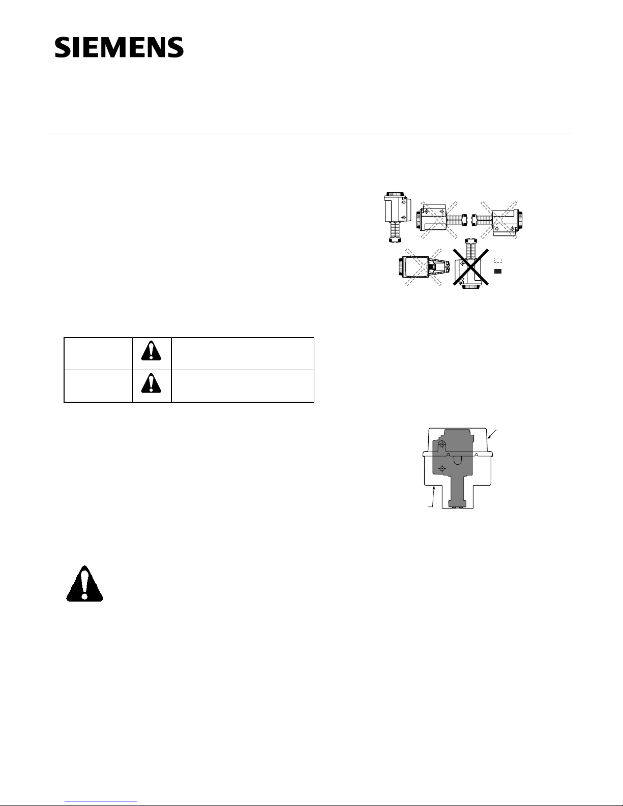
Mounting Positions
EA0921R1
Figure 1. Acceptable Mounting Positions.
Using the Weather Shield
The SKD62UA must be in the vertical position.
Complete instructions for the mounting of the weather
shield are included with that product.
NOTE: Use the top knockout position when installing
the Weather Shield. See Figure 13.
Not allowed with the
Weather Shield
Not allowed in
any circumstance
Required Tools
• 5 mm hex wrench
• Small and medium flat-blade screwdrivers
Expected Installation Time
20 minutes for factory installed actuator
45 minutes for field replacement of actuator
Prerequisites
WARNING:
If mounting the actuator to a valve
already in line, either close the shut-off
valves in the piping (upstream first,
then downstream) or switch off the
pump to allow the differential and static
pressure in the valve to drop.
VENTILATION
OPENINGS
VENTILATION
OPENINGS
EA0857R1
Figure 2. Weather Shield Installation Position.
Item Code: 129-369, Rev. 011 Page 1 of 6
Document Number: 129-369
EA0382R1
EA0381R1
>3x360°
«AUTO
«
Installation Instructions
September 30, 2002
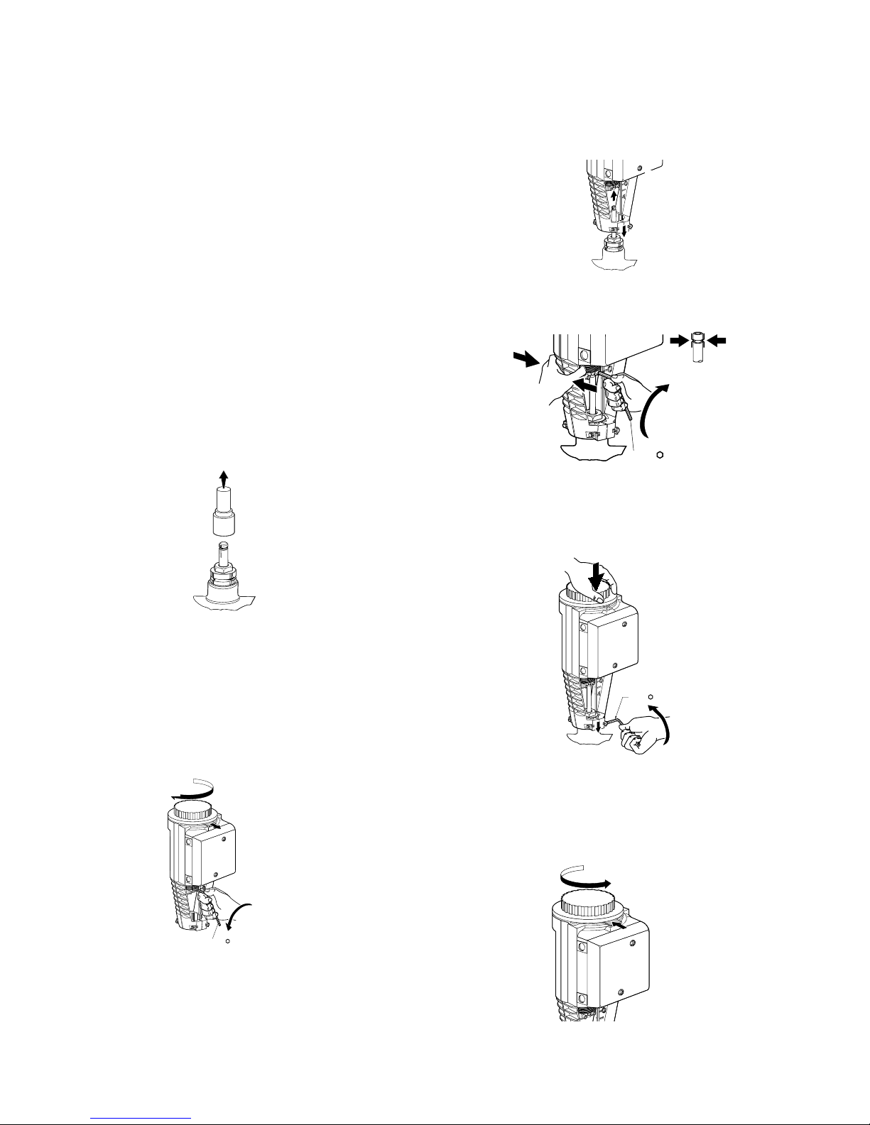
Installation
If you are mounting an actuator on a new valve, begin
with the instructions in Figure 3.
Removing the Actuator
from the Valve
1. Remove the actuator cover.
2. Disconnect the wires and conduit, if installed.
3. Loosen the valve stem retainer using a 5 mm hex
wrench and lower the valve stem into the valve.
4. Loosen the yoke nuts in the actuator yoke using a
5 mm hex wrench.
5. Remove the actuator from the valve, use care not
to damage the valve stem.
Continue with Mounting an Actuator to a Valve.
4
3
Figure 5.
5
EA0384R1
NOTE: Hold the stem retainer in place as you tighten
it around the valve stem. See Figure 6.
5 mm
Figure 6.
EA0134R1
Figure 3. Preparing a new Valve.
Mounting an Actuator to a Valve.
MAX. TORQUE
5 mm
40 lb-in (4.5 Nm)
NOTE: Install the packing heating element,
(P/N 599-00417), if used, before proceeding.
1
≈3x360°
«MAN«MAN
«
NOTE: Position the actuator to accommodate the
wiring. Hold the actuator in place while
EA0383R2
Figure 7.
tightening the yoke nuts. See Figure 7.
EA0380R1
NOTE: Make sure the yoke nuts are loose enough to
allow the actuator to slip over the bonnet.
Figure 4.
5 mm
≈5 x 360°
See Figure 5.
Figure 8.
Page 2 of 6 Siemens Building Technologies, Inc.
6
6
 Loading...