

Page 1
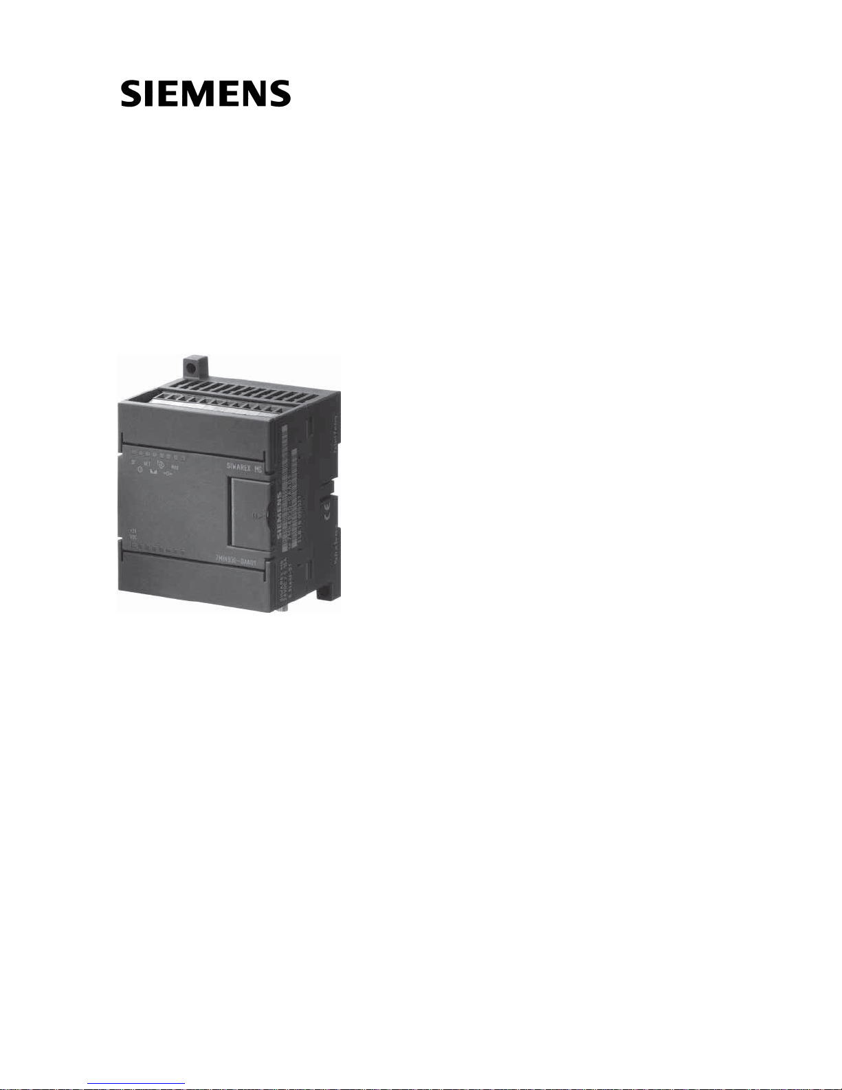
SIWAREX MS
Weighing Module for Level Measurement, Weighbridges etc.
Calibrating SIWAREX MS with SIWATOOL MS
Quick Guide
For modules with order number 7MH4930-0AA01
Contents
1. Hardware Requirements...............................................................................................3
2. Siwarex MS connections ..............................................................................................6
3. Establish the communication to the Siwarex MS module .............................................8
4. Adjustment with an adjustment weight..........................................................................9
4.1 Set the SIWATOOL parameters........................................................................9
4.2 Adjustment procedure.....................................................................................12
5. Adjustment without an adjustment weight (theoretical adjustment)............................14
6. Create a Siwatool backup file .....................................................................................18
©Siemens AG 1
SIWAREX_MS_Quick Guide_V4.0.doc, 12/2010
Page 2

Introduction
SIWAREX MS is a compact weighing module for SIMATIC Automation System S7-200.
Main applications are bin scales, weighbridges, crane scales, force and tightening torque
measuring.
Purpose of this document for functional safety
This programming manual contains all information that you will require to commission and
use the device.
It is aimed at persons who install the device mechanically, connect it electrically,
parameterize and commission it, as well as at service and maintenance engineers.
Notes on warranty
The contents of this programming manual shall not become part of or modify any prior or
existing agreement, commitment or legal relationship. All obligations on the part of
Siemens AG are contained in the respective sales contract, which also contains the
complete and solely applicable warranty conditions. Any statements on the device
versions described in the programming manual do not create new warranties or modify the
existing warranty.
The content reflects the technical status at the time of printing. We reserve the right to
make technical changes in the course of further development.
Validation of this document
This documentation is only valid in conjunction with the manual SIWAREX MS. This
manual is available on the Siemens homepage.
http://support.automation.siemens.com/WW/view/en/22600601
©Siemens AG 2
SIWAREX_MS_Quick Guide_V4.0.doc, 12/2010
Page 3
1. Hardware Requirements
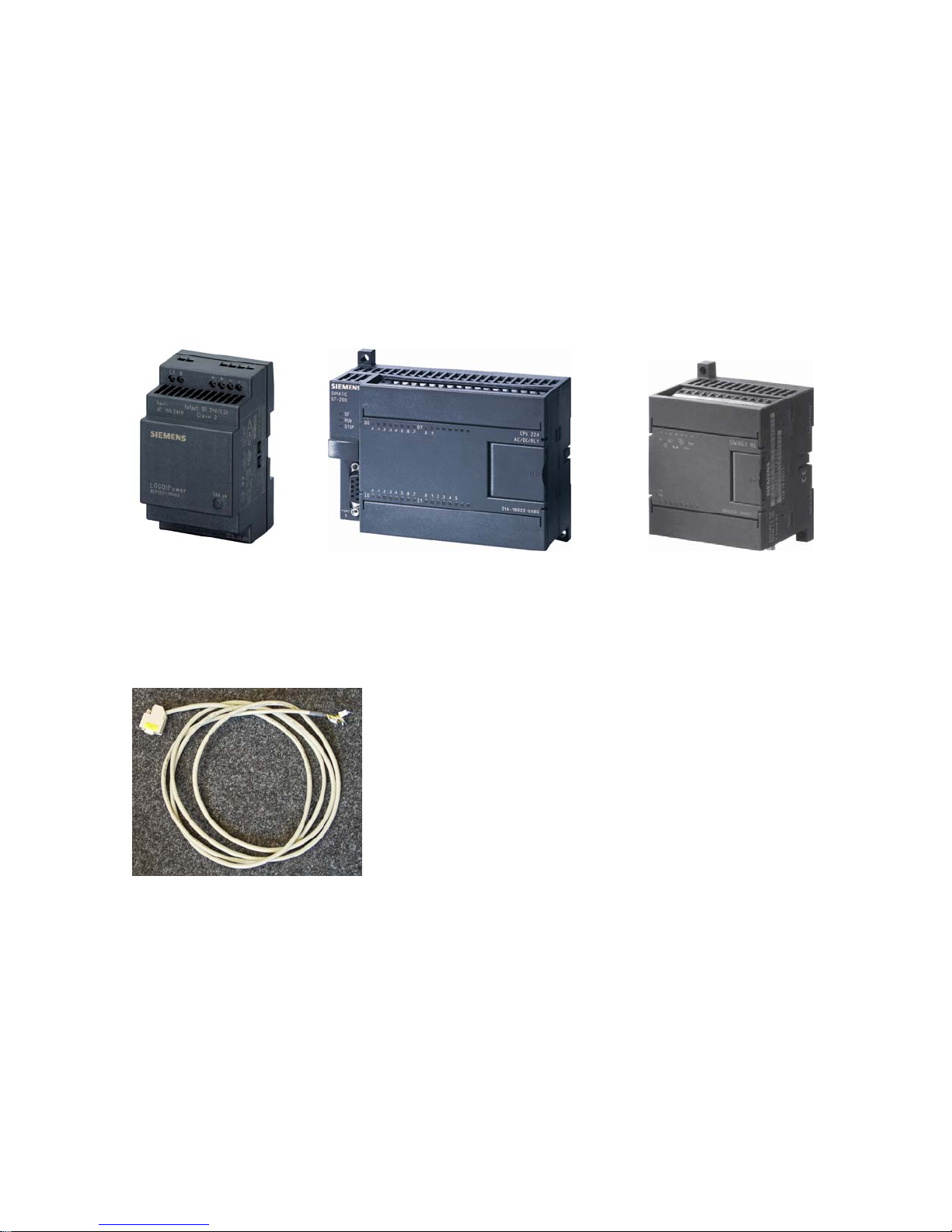
Following hardware parts and software are requested to integrate a scale into SIMATIC
S7-200: SIWAREX MS module, 24V Power Module, S7-200 CPU, SIWATOOL MS
configuration package, RS232 cable, computer with Windows XP or higher and a
calibration weight bigger than 5% of the sum of the nominal value of all load cells.
24V Power Supply SIMATIC CPU S7-200 SIWAREX MS
7MH4930-0AA01
SIWATOOL RS232 Cable
7MH4607-8CA
©Siemens AG 3
SIWAREX_MS_Quick Guide_V4.0.doc, 12/2010
Page 4
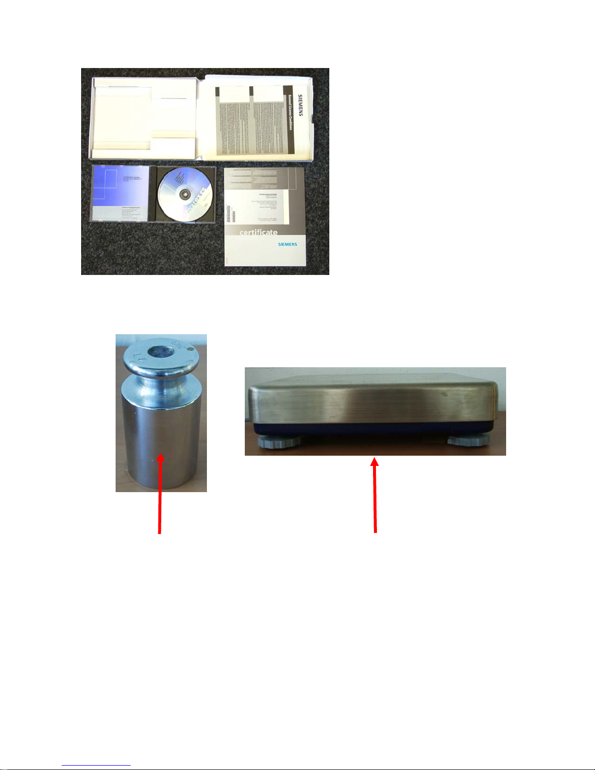
Configuration Package for SIWAREX MS:
7MH4930-0AK01
Adjustment weight Scale
( >5% of the sum of the nominal value
of all load cells)
©Siemens AG 4
SIWAREX_MS_Quick Guide_V4.0.doc, 12/2010
Page 5
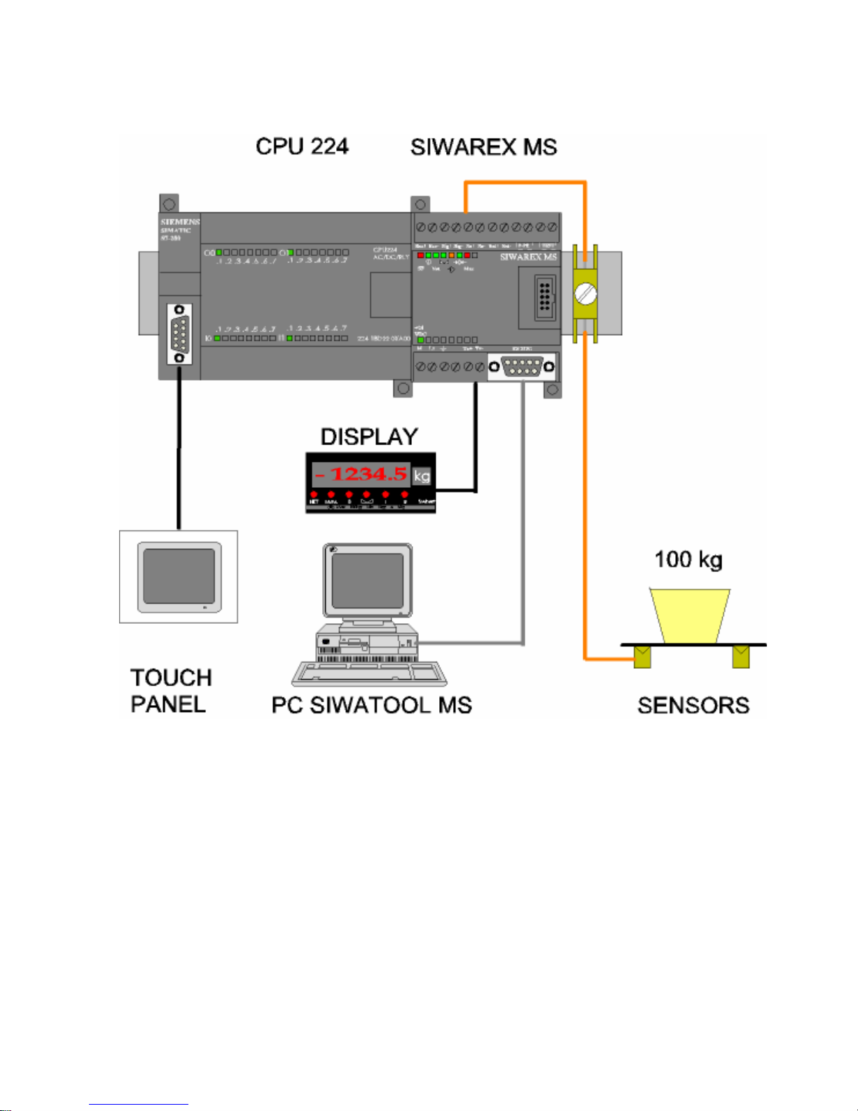
System Configuration
©Siemens AG 5
SIWAREX_MS_Quick Guide_V4.0.doc, 12/2010
Page 6
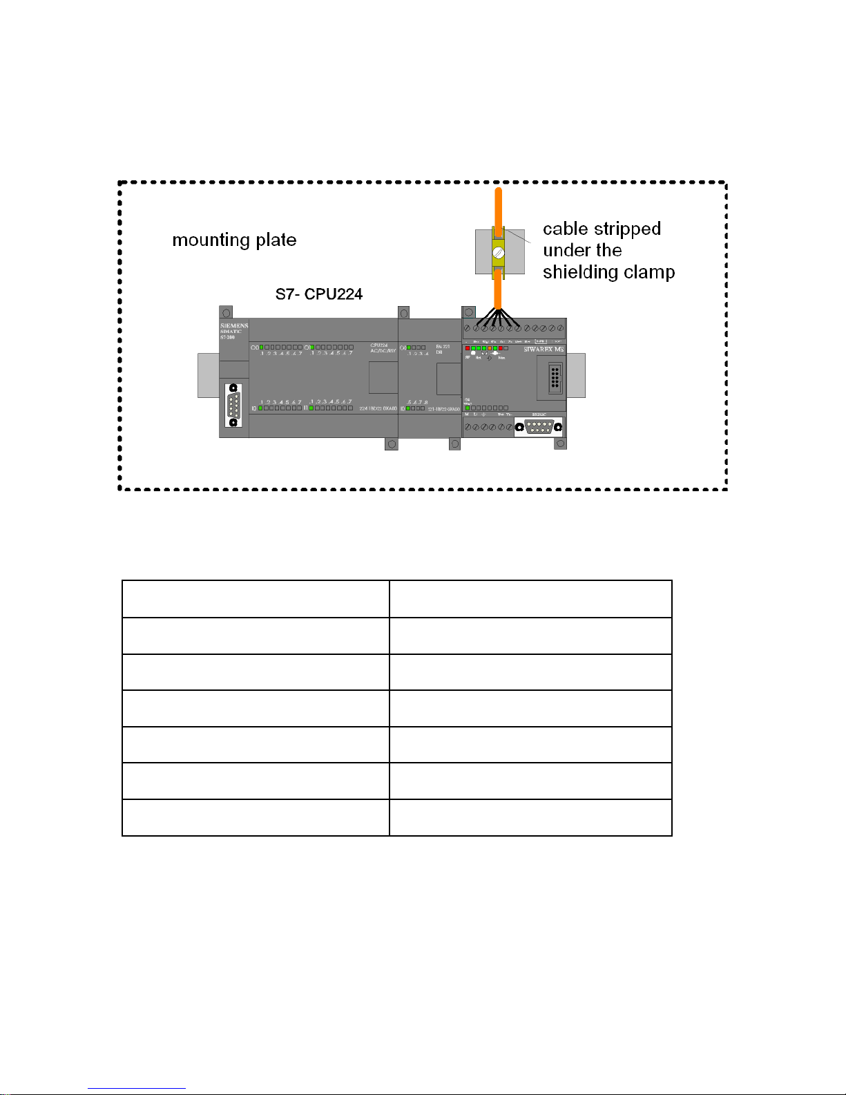
2. Siwarex MS connections
Load Cell Connection:
Connection and signal
designations
SEN+
SEN-
SIG+
SIG-
EXC+
EXC-
Sense line +
Sense line –
Measurement line +
Measurement line –
Load cell supply +
Load cell supply -
Comment
©Siemens AG 6
SIWAREX_MS_Quick Guide_V4.0.doc, 12/2010
Page 7
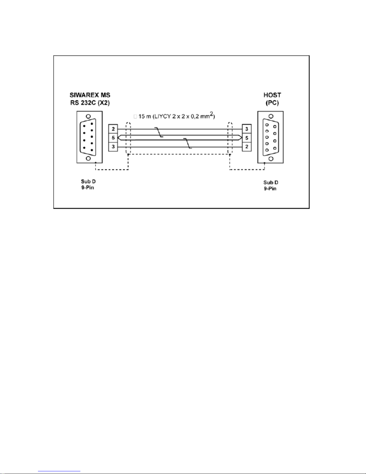
Connecting the PC for SIWATOOL MS:
©Siemens AG 7
SIWAREX_MS_Quick Guide_V4.0.doc, 12/2010
Page 8
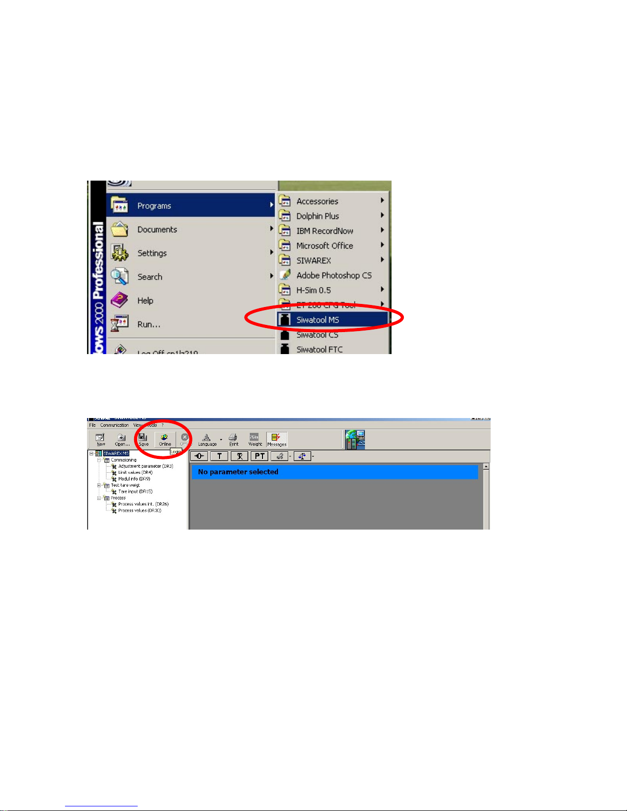
3. Establish the communication to the
Siwarex MS module
Start the Siwatool MS software into Windows:
For establishing the communication between the Siwarex MS module and the Siwatool
software, click the button Online:
©Siemens AG 8
SIWAREX_MS_Quick Guide_V4.0.doc, 12/2010
Page 9
4. Adjustment with an adjustment weight
4.1 Set the SIWATOOL parameters
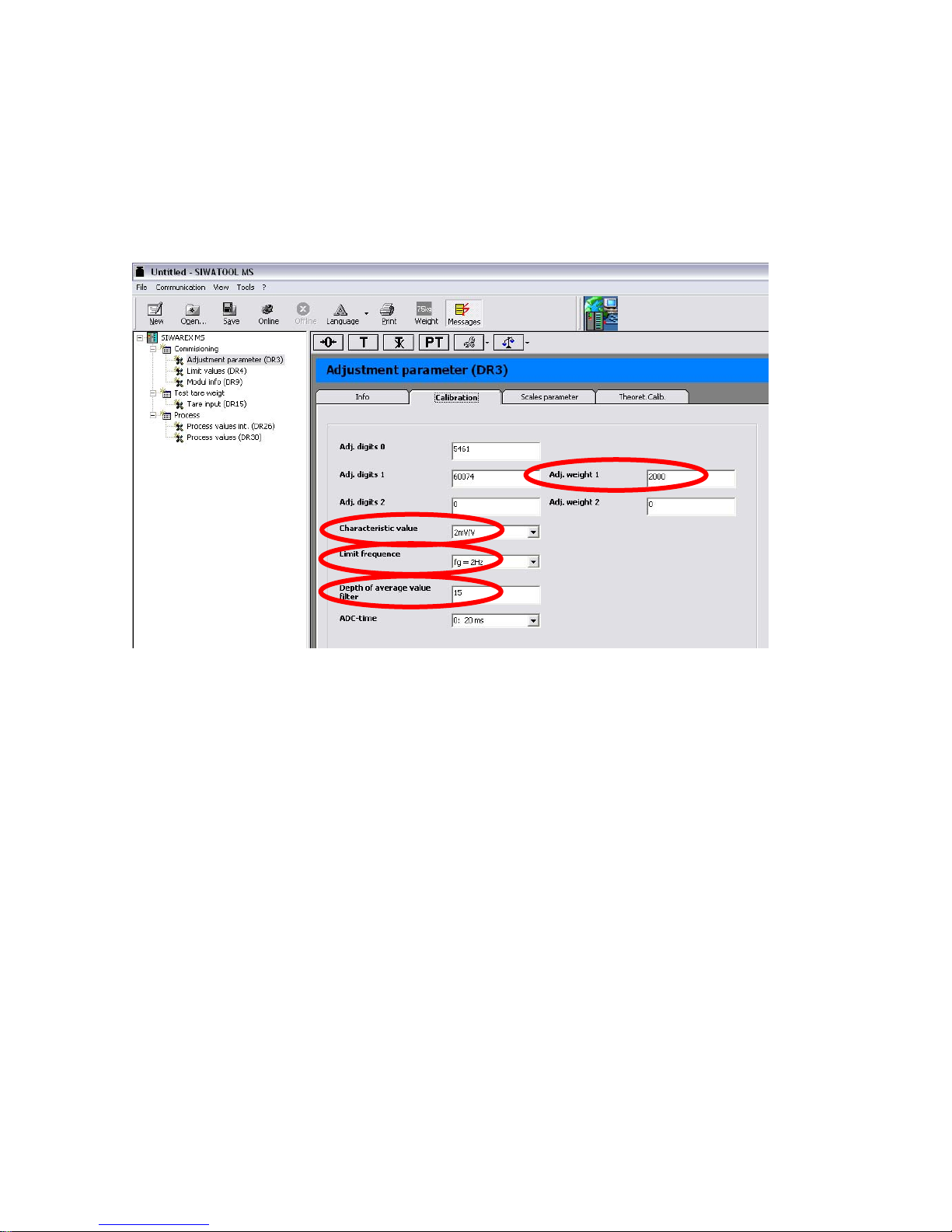
When the communication is established check the following parameter-settings:
Adj.weight 1:
Enter the value of the adjustment weight.
The adjustment weight is an integer-value (up to 32767).
For example:
a) For a 20 kg scale you may use a resolution of 1 g:
- the parameter “Adj. weight 1” is set into gram (e.g. “20000”).
- the parameter “Numeral step” (index card “Scales parameter”) is set to “1”.
- the parameter “Decimal point” (index card “Scales parameter”) is set to “0”.
- the parameter “Weight unit” (index card “Scales parameter”) is set to “gr”.
b) For a 40 kg scale you may use a resolution of 10 g:
- the parameter “Adj. weight 1” is set into gram x10 (e.g. “4000”).
- the parameter “Numeral step” (index card “Scales parameter”) is set to “1”.
- the parameter “Decimal point” (index card “Scales parameter”) is set to “2”.
- the parameter “Weight unit” (index card “Scales parameter”) is set to “kg”.
©Siemens AG 9
SIWAREX_MS_Quick Guide_V4.0.doc, 12/2010
Page 10
The decimal point is not part of the integer-value and is only used for the Siwatool-display
g
(and a remote display, if available).
That means the numeral step and the decimal point have to determine, so that the
displayed weight value (weight value = integer-value) will not increase the value of
32767.
Characteristic Value:
Characteristic value of the load cell.
The specification of the characteristic value can be read into the techincal data sheet of
the load cell.
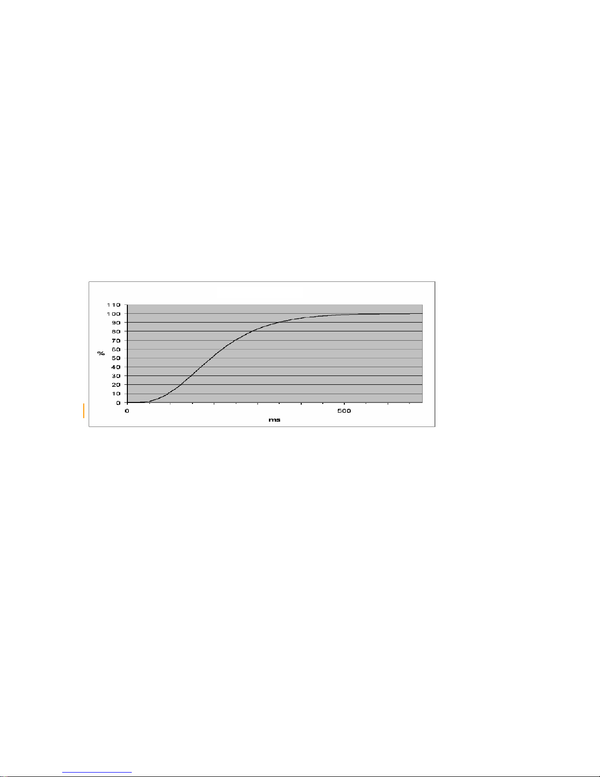
Limit frequence:
If this parameter is set to 5 Hz, the scale will respond quickly to a weight change; if it is set
to 0.05 Hz, the scale will “move slowly”.
Step response of the limit frequence of 2 Hz:
Critical dampin
Depth of average value filter:
The average value filter ensures a stable weight value and prevents interference.
The weight is measured according to the average value of n weight values.
If n = 10, 10 weight values will be used for calculating the average value. The earliest
value is discarded every 20 milliseconds and the latest value will be added for the
calculation.
©Siemens AG 10
SIWAREX_MS_Quick Guide_V4.0.doc, 12/2010
Page 11
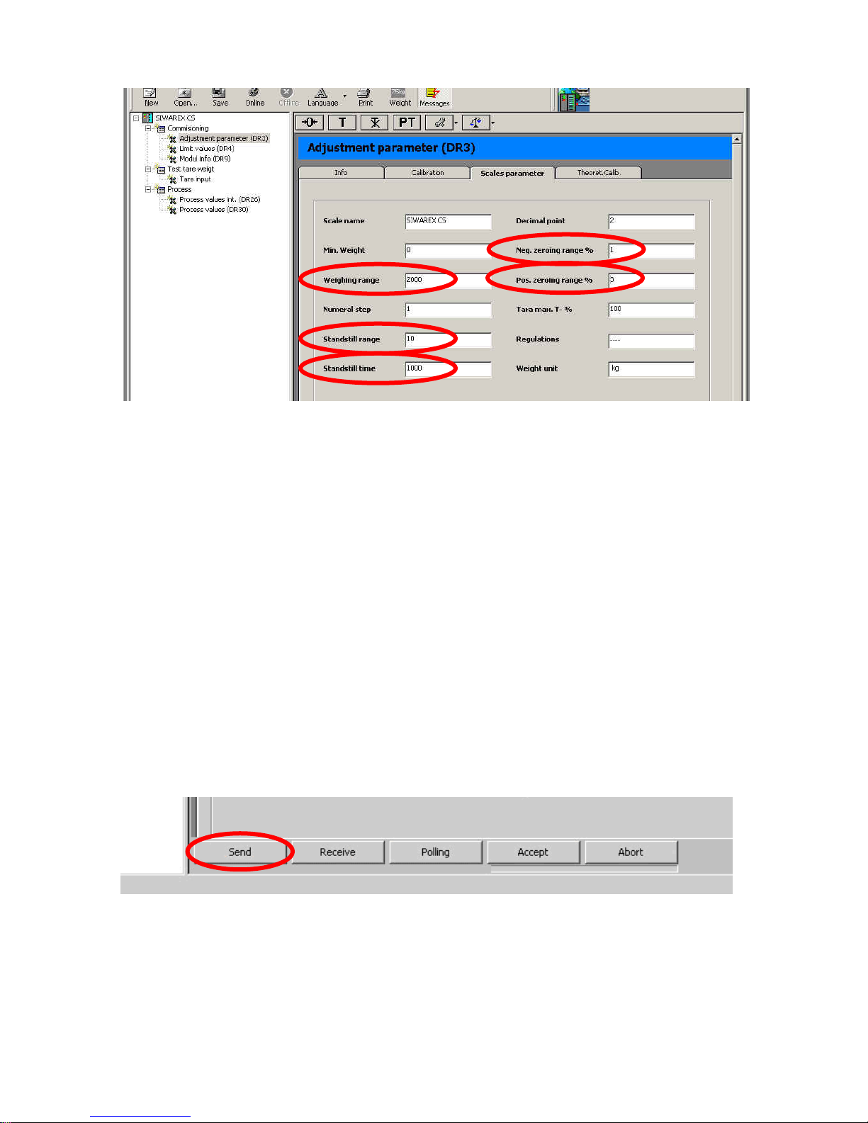
Standstill range and Standstill time:
Standstill range and Standstill time (in msec) are used to monitor when the scale has
stand still.
If the weight change is lower than the specified range (standstill range) within the specified
period (standstill time) the scale stands still.
The monitoring of the scale standstill is used e.g. for the commands “zeroing” or “taring”.
Neg. zeroing range %, Pos. zeroing range % and Weighing range:
By executing the command “zeroing” the weight value is set to zero. With the parameters
“Neg. zeroing range %” and “Pos. zeroing range %” the zeroing range is defined. The
values are set as percent of the parameter “Weighing range”.
The parameter “Weighing range” is the maximum of material, which will put on the scale.
For example (see also the picture above):
The zeroing range is between -20 kg (-1% of 2000) and +60 kg (+3% of 2000).
Zeroing will be rejected if the current gross weight is too high or too low.
After setting the parameters, click Send to send the changed parameters to the Siwarex
MS module:
©Siemens AG 11
SIWAREX_MS_Quick Guide_V4.0.doc, 12/2010
Page 12
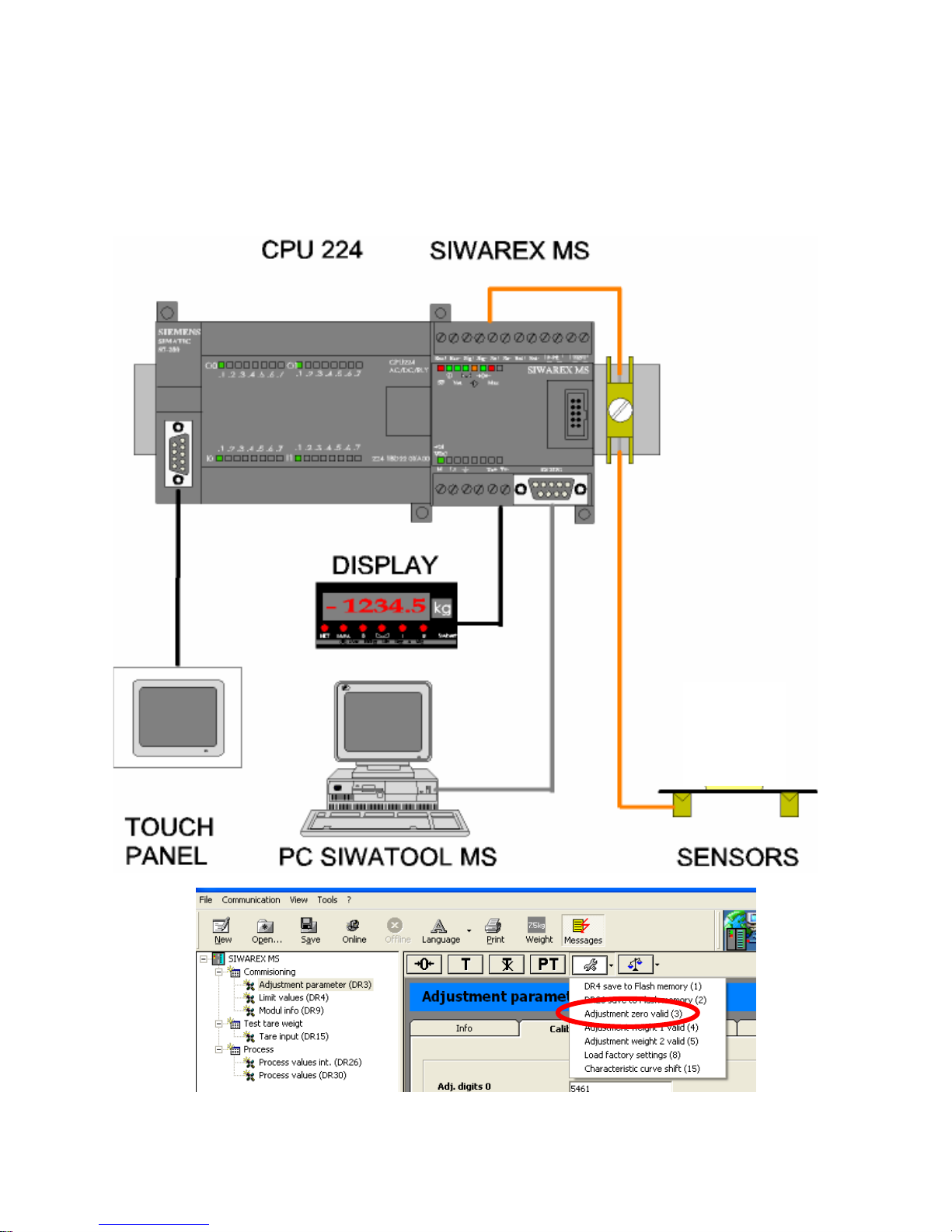
4.2 Adjustment procedure
Ensure that the scale is empty (not loaded) and execute the command Adjustment zero
valid (3).
The Siwarex MS module shows now the weight value “0”.
7 Calibration Procedure
Ensure that the scale is empty (not loaded) and click Adjustment zero valid (3).
0 kg
©Siemens AG 12
SIWAREX_MS_Quick Guide_V4.0.doc, 12/2010
Page 13
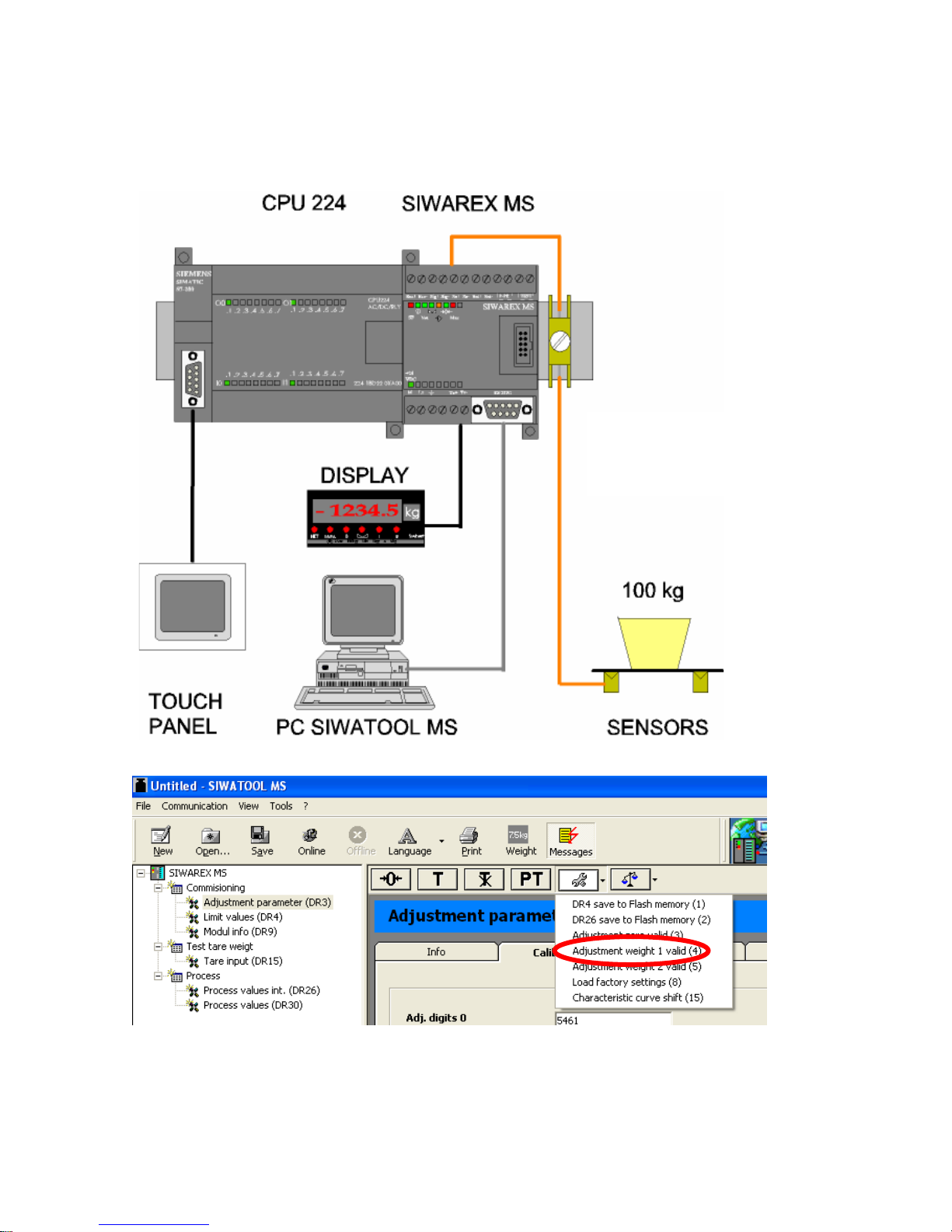
Afterwards, place the adjustment weight on the scale and execute the command
Adjustment weight 1 valid (4). With executing of this command, the adjustment line is
detected of the scale.
The Siwarex MS module shows now the adjustment weight.
Adjustment
Weight
The adjustment is completed now.
©Siemens AG 13
SIWAREX_MS_Quick Guide_V4.0.doc, 12/2010
Page 14
5. Adjustment without an adjustment
weight (theoretical adjustment)
If the adjustment is not possible by using adjustment weights, the scale can also be
adjusted without adjustment weights, if the mechanical structure of the scale is correct.
If the measuring logs are available, these logs can be used for the theoretical adjustment.
If the measuring logs aren’t available, the default-values of the load cells can be used of
the technical data sheet.
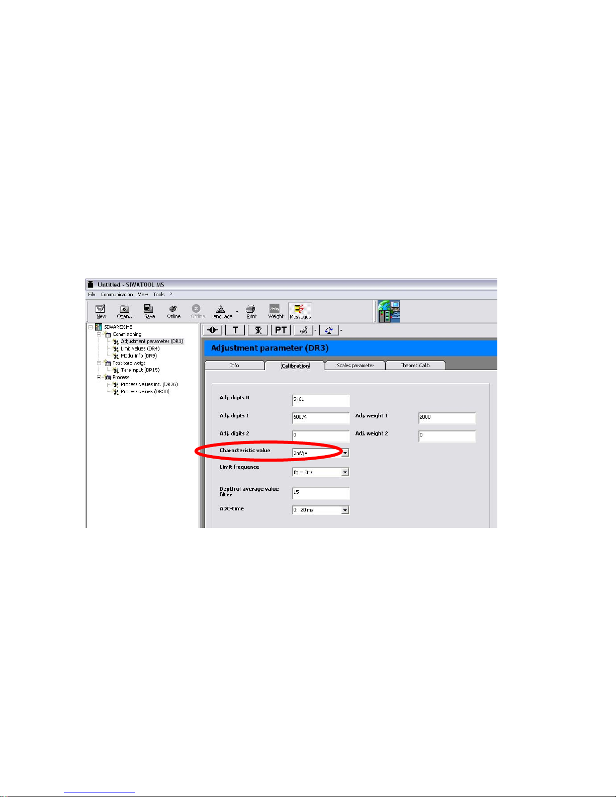
The execution of the theoretical adjustment is handled with the help of the SIWATOOL MS
software.
First, the "Characteristic value" (e.g. “2 mV/V”) must be defined in the DR3, index card:
"Calibration":
©Siemens AG 14
SIWAREX_MS_Quick Guide_V4.0.doc, 12/2010
Page 15
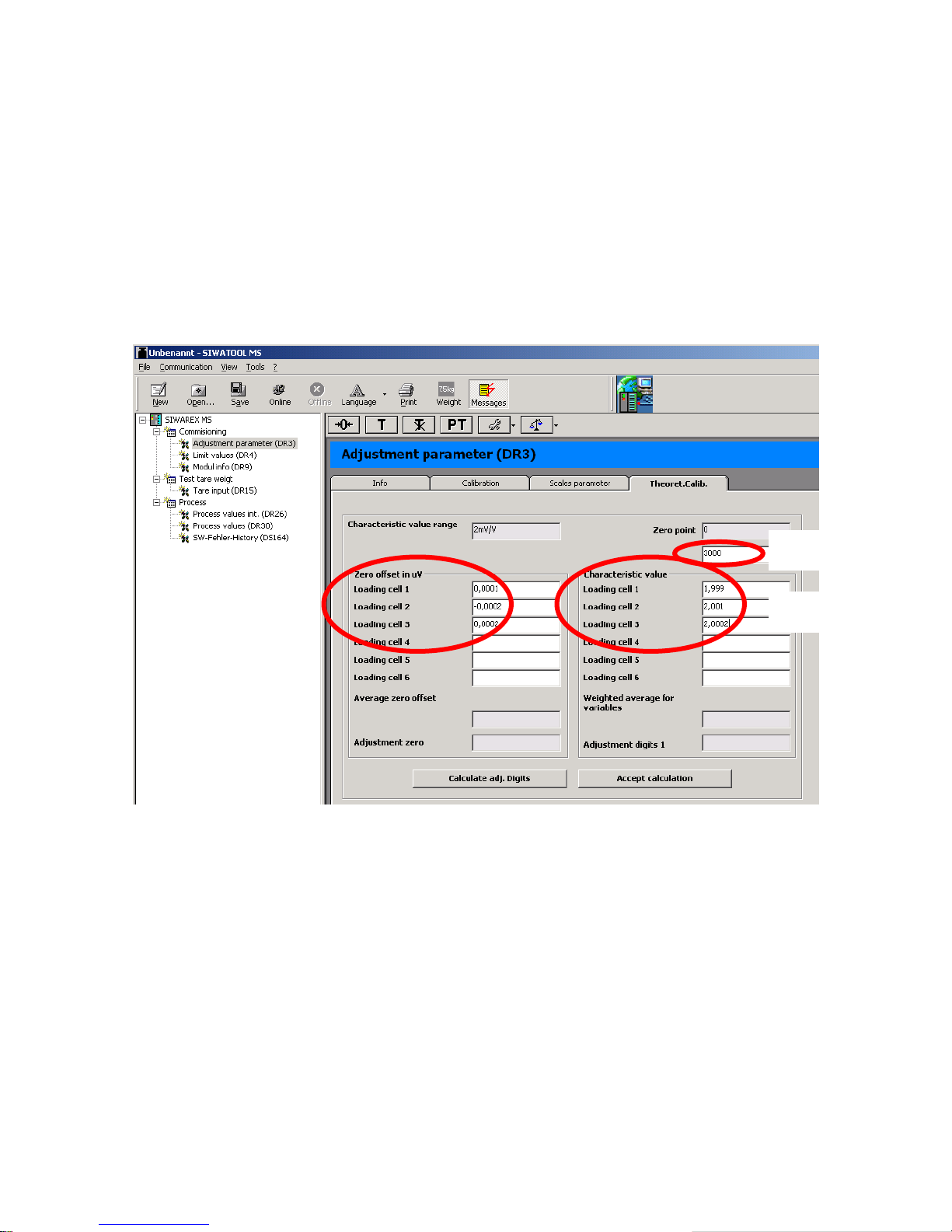
Then, switch to the "Theoret. Calib." index card.
To execute the theoretical adjustment, the rated load for all load cells is defined first,
e.g. 3 load cells with 1,000 kg each result in a rated load of 3,000 kg.
(See also step “1.” in the picture below)
The “Zero offset in uV/V” (unit = μV/V), and the “Characteristic value” (unit = mV/V) is then
entered for each individual load cell.
(See also step “2.” and “3.” in the picture below)
These values are taken from the respective load cell measuring log.
If the measuring logs aren’t available, the default-values can be used,
e.g. “Zero offset in uV/V” = “0” and “Characteristic value” = “2.0”:
1.
2.
3.
©Siemens AG 15
SIWAREX_MS_Quick Guide_V4.0.doc, 12/2010
Page 16
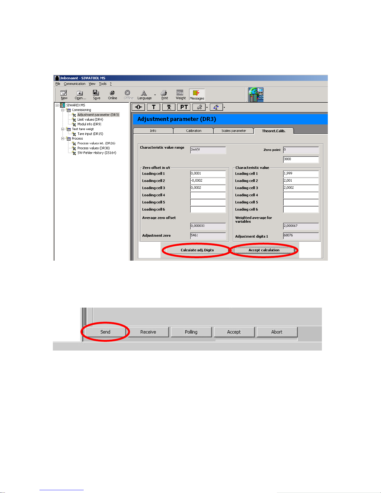
After entering the data for each load cell, the adjustment digits are calculated and
the result is displayed by actuating the button "Calculate adj. Digits".
Then, the calculated adjustment digits can be integrated into the DR3 by actuating the
button "Accept calculation":
1. 2.
The DR3 is then sent to the weight module with the new adjustment data with the button
"Send":
©Siemens AG 16
SIWAREX_MS_Quick Guide_V4.0.doc, 12/2010
Page 17
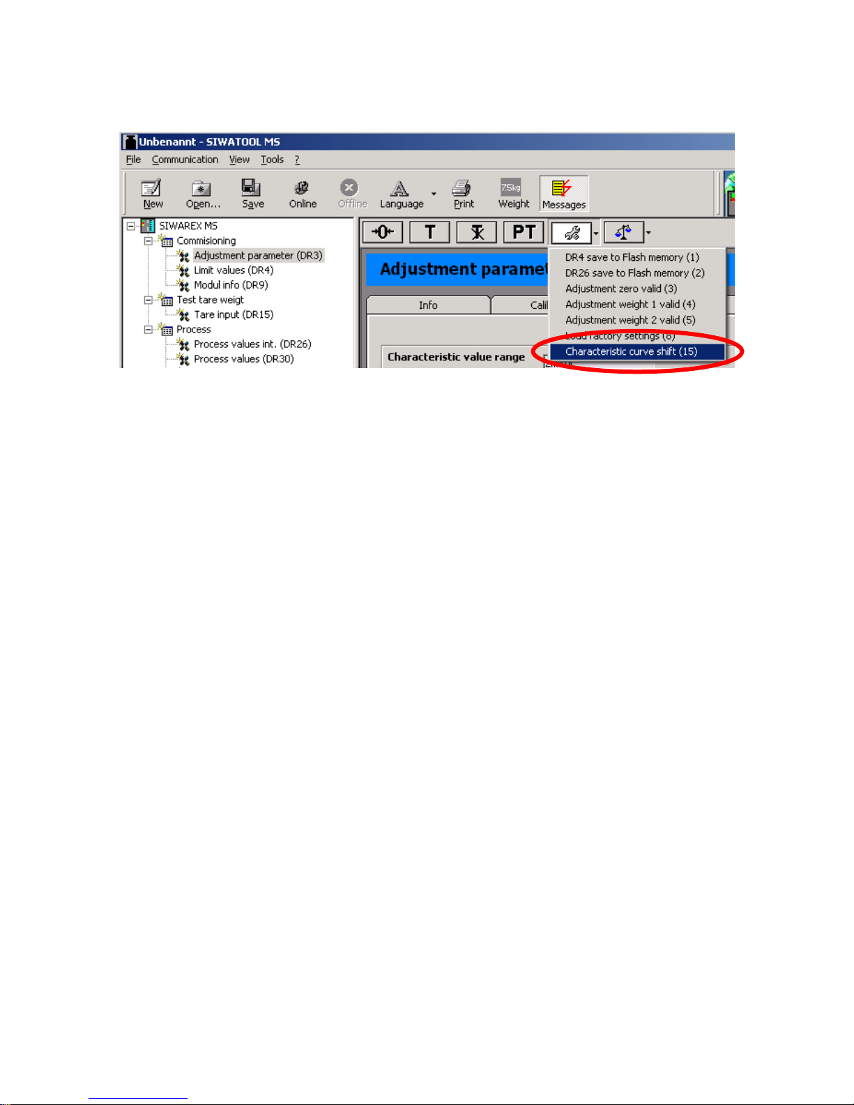
After sending the DR3, the command “Characteristic curve shift (15)" has to be executed,
when the scale is empty.
The theoretical adjustment is now finished.
©Siemens AG 17
SIWAREX_MS_Quick Guide_V4.0.doc, 12/2010
Page 18
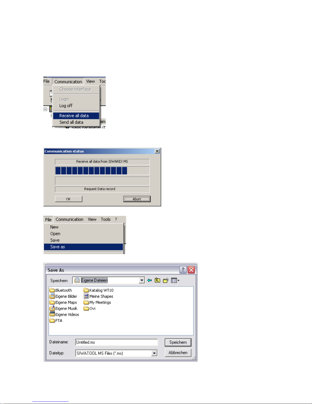
6. Create a Siwatool backup file
Eventually you may save all parameter settings of the Siwarex MS module into a file
Receive all data from the Siwarex MS module the Siwatool software:
During the transmission from the Siwarex MS module to the PC, the following messagewindow appears:
Save the data as a Siwatool MS File:
©Siemens AG 18
SIWAREX_MS_Quick Guide_V4.0.doc, 12/2010
Page 19

If you have any issues or suggestions regarding the related products or documents,
please feel free to contact:
Technical support for SIWAREX:
Siemens AG
Industry Automation (IA)
Sensors and Communication
Process Instrumentation
D-76181 Karlsruhe
Germany
Tel: +49 721 595 2811
Fax: +49 721 595 2901
E-mail: [email protected]
Website: www.siemens.com/siwarex
Copyright Statement
All rights reserved by Siemens AG
This document is subject to change without notice. Under no circumstances
shall the content of this document be construed as an express or implied
promise, guarantee (for any method, product or equipment) or implication by or
from Siemens AG. Partial or full replication or translation of this document
without written permission from Siemens AG is illegal.
©Siemens AG 19
SIWAREX_MS_Quick Guide_V4.0.doc, 12/2010
 Loading...