

Page 1
SIWAREX JB stainless steel with ATEX
certificate
_
_________________
_
_
_________________
_
_
_________________
_
_
_________________
_
_
_________________
_
_
__________________
_
_________________
_
_
_________________
_
Weighing systems
SIWAREX JB stainless steel
with ATEX certificate
Compact Operating Instructions
06/2010
A5E01257284C-01
Introduction
1
Notes on handling the
product
2
Description
3
Application planning
4
Installing and connecting
5
Technical data
6
Ordering data
7
Appendix
A
Page 2
Legal information
Legal information
Warning notice system
This manual contains notices you have to observe in order to ensure your personal safety, as well as to prevent
damage to property. The notices referring to your personal safety are highlighted in the manual by a safety alert
symbol, notices referring only to property damage have no safety alert symbol. These notices shown below are
graded according to the degree of danger.
DANGER
indicates that death or severe personal injury will result if proper precautions are not taken.
WARNING
indicates that death or severe personal injury may result if proper precautions are not taken.
CAUTION
with a safety alert symbol, indicates that minor personal injury can result if proper precautions are not taken.
CAUTION
without a safety alert symbol, indicates that property damage can result if proper precautions are not taken.
NOTICE
indicates that an unintended result or situation can occur if the corresponding information is not taken into
account.
If more than one degree of danger is present, the warning notice representing the highest degree of danger will
be used. A notice warning of injury to persons with a safety alert symbol may also include a warning relating to
property damage.
Qualified Personnel
The product/system described in this documentation may be operated only by personnel qualified for the specific
task in accordance with the relevant documentation for the specific task, in particular its warning notices and
safety instructions. Qualified personnel are those who, based on their training and experience, are capable of
identifying risks and avoiding potential hazards when working with these products/systems.
Proper use of Siemens products
Note the following:
WARNING
Siemens products may only be used for the applications described in the catalog and in the relevant technical
documentation. If products and components from other manufacturers are used, these must be recommended
or approved by Siemens. Proper transport, storage, installation, assembly, commissioning, operation and
maintenance are required to ensure that the products operate safely and without any problems. The permissible
ambient conditions must be adhered to. The information in the relevant documentation must be observed.
Trademarks
All names identified by ® are registered trademarks of the Siemens AG. The remaining trademarks in this
publication may be trademarks whose use by third parties for their own purposes could violate the rights of the
owner.
Disclaimer of Liability
We have reviewed the contents of this publication to ensure consistency with the hardware and software
described. Since variance cannot be precluded entirely, we cannot guarantee full consistency. However, the
information in this publication is reviewed regularly and any necessary corrections are included in subsequent
editions.
Siemens AG
Industry Sector
Postfach 48 48
90026 NÜRNBERG
GERMANY
A5E01257284C-01
Ⓟ 07/2010
Copyright © Siemens AG 2010.
Technical data subject to change
Page 3

SIWAREX JB stainless steel with ATEX certificate
Compact Operating Instructions, 06/2010, A5E01257284C-01
3
Table of contents
1 Introduction................................................................................................................................................ 4
1.1 Purpose of this documentation ......................................................................................................4
1.2 History............................................................................................................................................4
1.3 Trademarks....................................................................................................................................4
1.4 Environmental protection ...............................................................................................................4
2 Notes on handling
t
he product................................................................................................................... 5
3 Description................................................................................................................................................. 7
3.1 Applications....................................................................................................................................7
3.2 Properties.......................................................................................................................................8
3.3 Design............................................................................................................................................8
4 Application pl
anning
................................................................................................................................. 10
4.1 Alternative EMC ca
ble glands......................................................................................................10
4.2 Selection of suitable cables ..................................................................................................
.......10
5 Installing and connecting
......................................................................................................................... 12
5.1 Qualified personnel ......................................................................................................................12
5.2 Mounting ......................................................................................................................................12
5.3 Connecting principle ....................................................................................................................13
5.4 Connection...................................................................................................................................15
5.4.1 Installing the EMC cable glands
and the screw plugs .................................................................15
5.4.2 Connecting the shielding..............................................................................................................16
5.4.3 Installing the spring-loaded terminal block in the enclosure........................................................16
5.4.4 Connecting spring-loaded t
e
rminals ............................................................................................17
5.4.5 Screwing on the cover .................................................................................................................18
6 Technical
data ................................................................................................................
......................... 19
6.1 Ambient conditions.......................................................................................................................19
6.2 Mechanical and electrical data.....................................................................................................19
6.3 Explosion protection.....................................................................................................................20
6.4 Electromagnetic compatibility ......................................................................................................20
6.5 Dimension drawing ......................................................................................................................21
7 Ordering dat
a
........................................................................................................................................... 22
7.1 Order no.......................................................................................................................................22
7.2 Accessories..................................................................................................................................22
A Appendix.................................................................................................................................................. 23
A.1 Technical support
.............................................................................................................
............23
Page 4

SIWAREX JB stainless steel with ATEX certificate
4 Compact Operating Instructions, 06/2010, A5E01257284C-01
Introduction
1
1.1 Purpose of this documentation
These instructions contain all the information you need for commissioning and using the
device.
They are directed at persons who mechanically assemble, connect, start up, and use the
device.
1.2 History
The following versions of this documentation have been released to date. The changes apply
to the previous version:
Edition Comment / change
06/2010 Initial release
1.3 Trademarks
SIWAREX ® is a registered trademark of Siemens AG.
All other names appearing in these instructions may be trademarks whose use by third
parties for their own purposes may infringe upon owners rights.
1.4 Environmental protection
Devices described in this programming manual can be recycled owing to the low content of
noxious substances in their version. Please contact a certified waste disposal company for
eco-friendly recycling and to dispose of your old devices.
Page 5

SIWAREX JB stainless steel with ATEX certificate
Compact Operating Instructions, 06/2010, A5E01257284C-01
5
Notes on handling the product
2
Proper usage
Proper usage means that this product must only be used within the scope of the technical
specifications and intended purposes of these operating instructions.
If this device is used properly in compliance with the safety notices, this device will not
present any danger.
This device can only function correctly and safely if it is transported, stored, set up and
mounted correctly.
Correct operation of the device must be ensured by complying with the technical
specifications.
Improper handling can result in death, personal injury or property damage.
Notes on liability for defects
We expressly point out that the product quality is exclusively and conclusively described in
the sales contract. The content of this product documentation is neither part of a previous or
existing agreement, promise or legal relationship, nor is it intended to modify these. All
obligations on the part of Siemens AG are contained in the respective sales contract, which
also contains the complete and solely applicable liability provisions. The provisions defined
in the sales contract for the responsibility for defects are neither extended nor limited by the
remarks in this document.
Delivery information
The current scope of delivery is listed on the shipping documents enclosed with the delivery
in accordance with the valid sales contract.
When opening the packaging, please observe the relevant information. Check the delivery
for completeness and undamaged condition. In particular, the order number on the rating
plate must be compared to the ordering data.
Before you start work, please read these operating instructions. They contain important
information and data whose observation ensures the general safety and functionality of this
device. The manual will help you to handle this product more easily and efficiently, allowing
you to achieve reliable measuring results.
Page 6
Notes on handling the product
SIWAREX JB stainless steel with ATEX certificate
6 Compact Operating Instructions, 06/2010, A5E01257284C-01
Qualified personnel
In the context of this documentation, qualified personnel are people who are familiar with the
installation, mounting, commissioning, and operation of the product.
These people must have the following qualifications:
● They must be trained, instructed and authorized to operate and maintain devices and
systems in accordance with their place of work and in compliance with the safety
engineering standards for
– Electrical circuits
– High pressures
– Corrosive and hazardous media
● They must be trained, instructed and authorized to maintain and use appropriate safety
equipment according to the standards for safety engineering.
● In the case of devices with explosion protection, qualified persons must be trained,
instructed and authorized to perform work on electrical circuits in plants subject to
explosion hazards.
Important notes on connecting
WARNING
Electric shock
The SIWAREX JB junction box must only be used with extra-low voltages ≤ 30 V.
Important notes on cleaning
CAUTION
Malfunction
Do not subject the junction box directly to the jet from a high-pressure cleaner.
Explosion protection
WARNING
Danger of explosion
Observe the test certificates, provisions and laws applicable in your country during
connection, assembly and operation. For hazardous areas, these are for example:
• IEC 60079-14 (international)
• EN 60079-14 (previously VDE0165, T1) (EU, Germany)
• The operational safety directive (Germany)
All work undertaken on electrical circuits in hazardous areas must only be performed by
skilled personnel.
Page 7
SIWAREX JB stainless steel with ATEX certificate
Compact Operating Instructions, 06/2010, A5E01257284C-01
7
Description
3
3.1 Applications
Field of application
The stainless steel SIWAREX JB junction box is used in weighing systems with extra-low
voltages ≤ 30 V.
The junction box can connect up to four load cells to the weighing module at the same time.
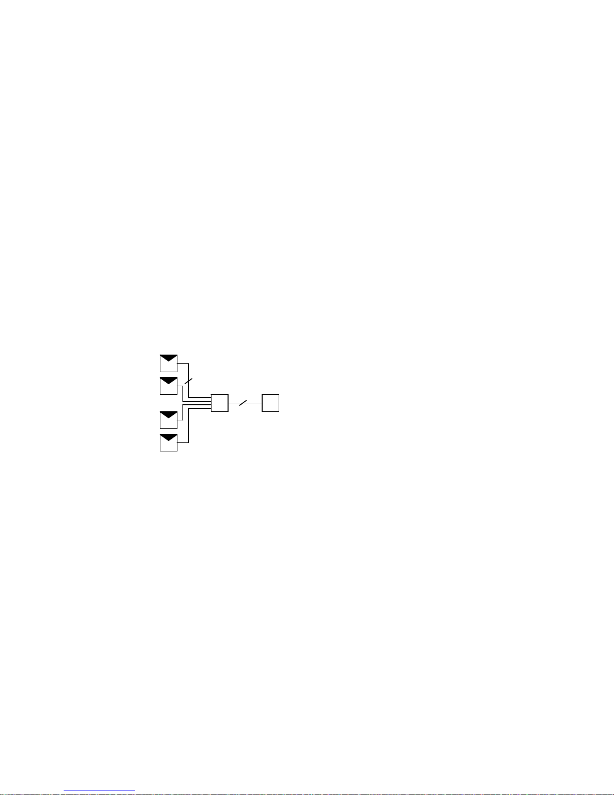
Operating principle
Load cells with 4-wire and 6-wire strain gauges can be connected.
The cable connection from the junction box to the weighing module is implemented with a 6-
wire cable.
LC
LCLC
LC
LC
JB W
6
4/6
LC
LCLC
LC
LC
JB W
6
4/6
LC Load cell
JB SIWAREX JB junction box
W Weighing module
Figure 3-1 Principle of application
Page 8
Description
3.2 Properties
SIWAREX JB stainless steel with ATEX certificate
8 Compact Operating Instructions, 06/2010, A5E01257284C-01
3.2 Properties
The SIWAREX JB junction box has the following properties:
● It consists of stainless, acid-resistant steel 1.4301.
● It is protected against dust and jet water according to protection class IP66.
● The junction box is maintenance-free.
● The cables are fed into the junction box via EMC cable glands.
– The cable glands are made of nickel-plated brass.
– Unneeded openings for cable glands are sealed with a cap screw.
● Electromagnetic compatibility:
Installing the shield in the cable glands provides a high degree of protection against
interference.
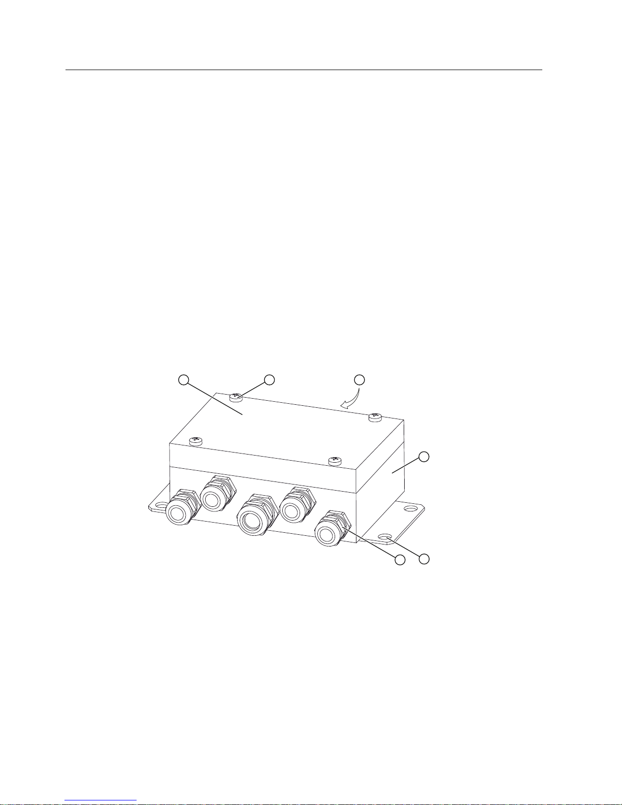
3.3 Design
SIWAREX JB stainless steel with ATEX certificate
① Cover
② Screw for cover (4x)
③ Rear side with nameplate and ATEX plate
④ Lower part
⑤ Support for mounting
⑥ EMC cable gland
Figure 3-2 Design
Page 9
Description
3.3 Design
SIWAREX JB stainless steel with ATEX certificate
Compact Operating Instructions, 06/2010, A5E01257284C-01
9
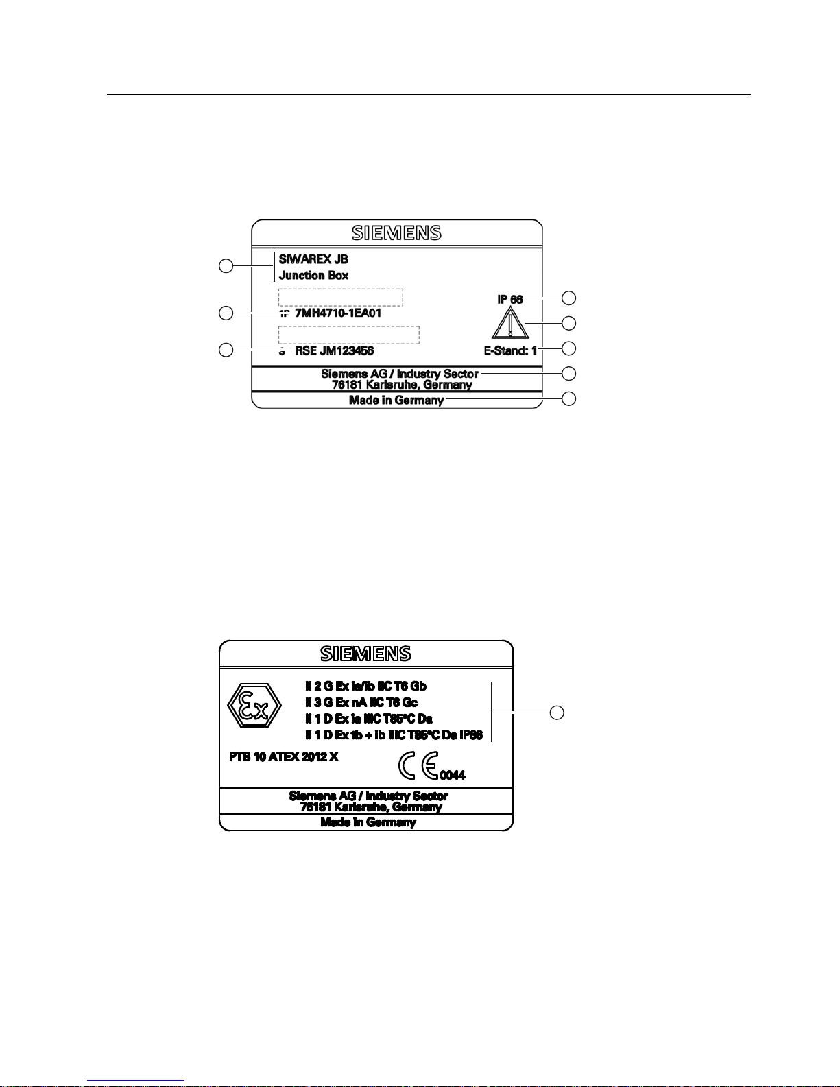
Nameplate
The nameplate shows the order number and other important product information.
The following example explains the information on the nameplate.
① Product name
② Degree of protection
③ Consult operating instructions
④ Development stage
⑤ Manufacturer
⑥ Country of origin
⑦ Serial number
⑧ Order no.
Figure 3-3 Nameplate
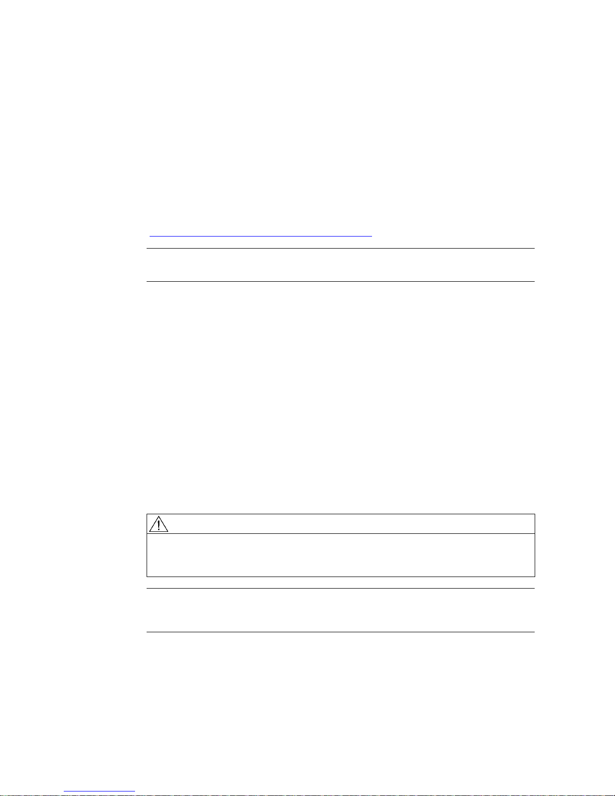
ATEX plate
① Certification data in accordance with ATEX
Figure 3-4 ATEX plate
Page 10
SIWAREX JB stainless steel with ATEX certificate
10 Compact Operating Instructions, 06/2010, A5E01257284C-01
Application planning
4
4.1 Alternative EMC cable glands
If you need stainless steel EMC cable glands, you can purchase them from corresponding
suppliers. Please note that the cable glands must be approved for the respective
applications. See Service and support
(http://www.siemens.com/automation/service&support
)
Note
Further information can be found under Ordering data (Page 22)
4.2 Selection of suitable cables
Signal cable
The junction box is connected to the weighing module by means of a signal cable. Use a
shielded cable with six cores as the signal cable. We recommend the SIWAREX cable
Li2Y2x0.75St+2x(2x0.34St)-CY:
● For standard applications: 7MH4702-8AG, orange sheath color.
● For intrinsically safe Ex applications: 7MH4702-8AF, light blue sheath color.
The cables and lines must correspond to the installation regulations according to EN 60079-
14. In hazardous areas, the diameter of individual conductors must not be smaller than 0.1
mm.
WARNING
Short circuit/explosion hazard
At an ambient temperature T ≥ 60 °C, use heat-resistant cables which are approved for an
ambient temperature at least 20 K higher.
Note
The maximum cable length between the load cell and the weighing module is stated in the
weighing module documentation.
Page 11
Application planning
4.2 Selection of suitable cables
SIWAREX JB stainless steel with ATEX certificate
Compact Operating Instructions, 06/2010, A5E01257284C-01
11
Suitable cables for spring-loaded terminals
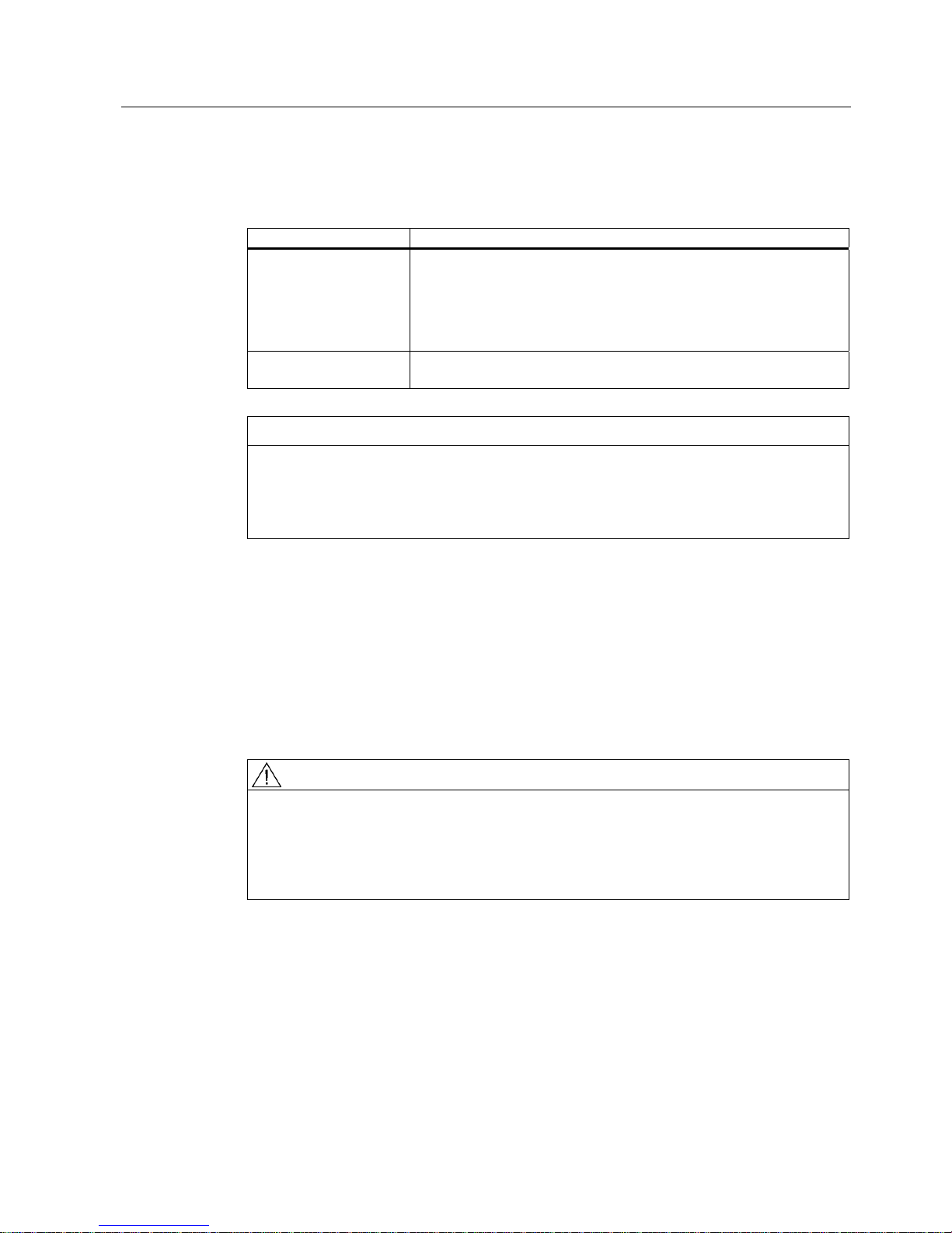
The following cables are suitable for connecting to the spring-loaded terminals
Cross section Design
0.08 ... 1.5 mm²
AWG 28 ... 16
• Solid
• Stranded
• Finely-stranded - with galvanized individual wires
• Finely-stranded - compacted strands
• Finely-stranded with gas-tight crimped-on pin cable lug
0.08 ... 1 mm²
AWG 28 ... 18
• Finely-stranded with gas-tight crimped-on end sleeves
CAUTION
Short-circuit
Use end sleeves for small conductor cross-sections.
Otherwise the stripped litz wire may buckle when it is inserted into the terminal. In this case,
the line is clamped onto the insulation, which will cause contact problems.
Load cell cables
DMS load cells are supplied with connecting cables.
Connecting a PAL cable
For non-intrinsically safe use of the junction box, a PAL cable must be connected. An M6x12
bolt is provided for this on the mounting flange. The PAL cable must be protected against
becoming loose on its own, which is achieved by a cable eye crimped to the cable.
WARNING
Danger of explosion
Please observe that in the case of shielded cables of intrinsically safe circuits in hazardous
areas, only one grounding is permissible.
If grounding is to be on both sides, an equipotential bonding conductor with at least 4 mm²
must be connected.
Page 12
SIWAREX JB stainless steel with ATEX certificate
12 Compact Operating Instructions, 06/2010, A5E01257284C-01
Installing and connecting
5
WARNING
Danger of explosion
Observe the test certificates, provisions and laws applicable in the country of operation
during connection, assembly, and operation.
For hazardous areas in Europe, for example, this is EN 60079-14.
5.1 Qualified personnel
The SIWAREX JB junction box must only be mounted and connected by qualified personnel.
5.2 Mounting
You can mount the SIWAREX JB junction box in any position. Preferrably, the cable glands
should point downward.
1. Prepare the location for mounting. Position the corresponding drill holes, see Dimension
draw
ing (Page 21).
2. Screw the jun
ction box tight with four screws.
Page 13
Installing and connecting
5.3 Connecting principle
SIWAREX JB stainless steel with ATEX certificate
Compact Operating Instructions, 06/2010, A5E01257284C-01
13
5.3 Connecting principle
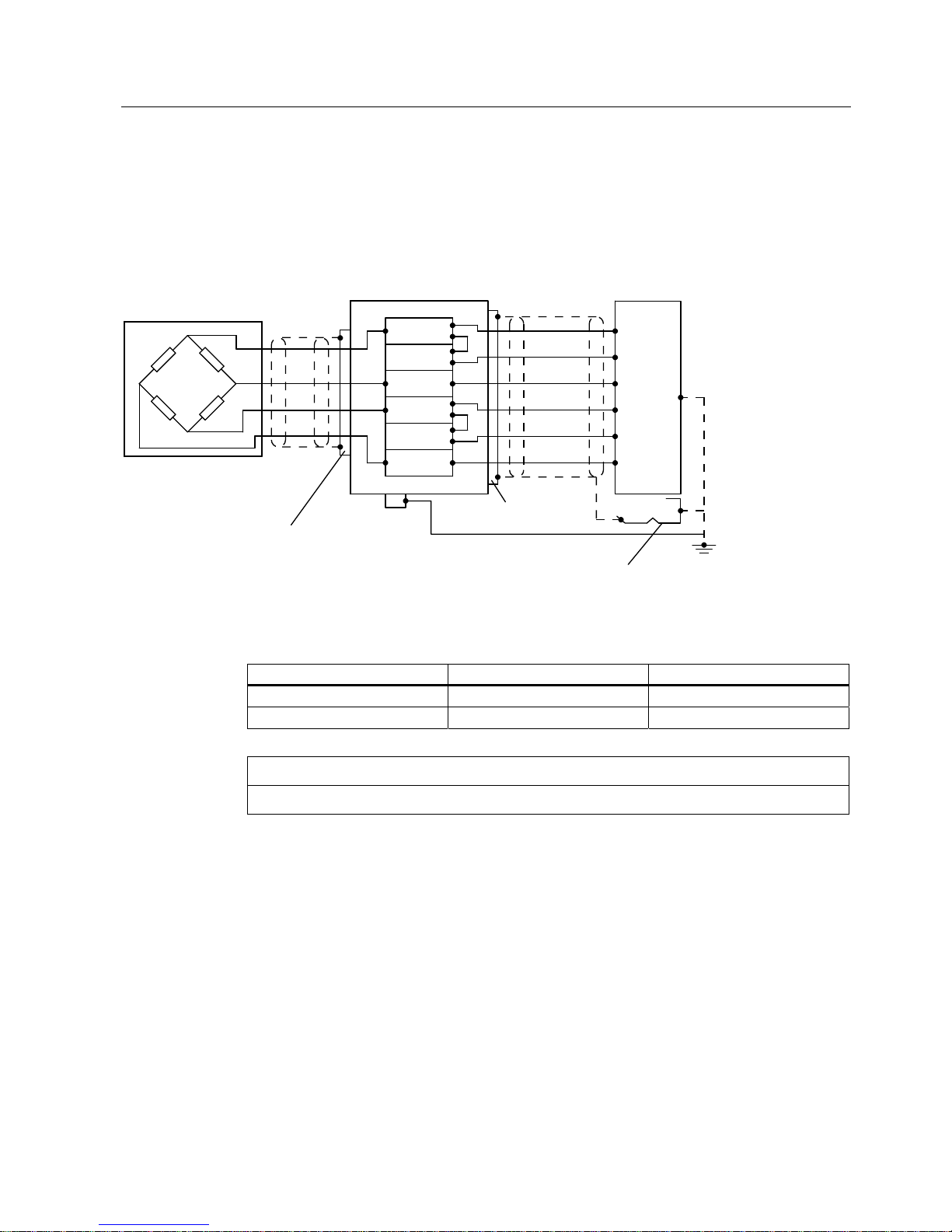
Load cells with four-wire system
1. Connect the load cells to the weighing module according to the circuit diagram.
&DEOHJODQG
&DEOHJODQG
6VKLHOGFRQQHFWLRQHOHPHQW
-XQFWLRQER[
6,:$5(;FDEOH
:HLJKLQJPRGXOH
%ODFN
*UD\
5HG
%OXH
*UHHQ
:KLWH
/RDGFHOO
EXC-
SENSE-
SIG-
EXC+
SENSE+
SIG+
SIG+
SENSE+
EXC+
SENSE-
EXC-
SIG-
3$/
Figure 5-1 Connecting principle for load cells with four-wire system
2. Install the following jumpers:
Jumper From terminal To terminal
1 EXC SENSE
2 EXC+ SENSE+
NOTICE
If the jumpers are missing, the weighing module will report a wire break.
Page 14
Installing and connecting
5.3 Connecting principle
SIWAREX JB stainless steel with ATEX certificate
14 Compact Operating Instructions, 06/2010, A5E01257284C-01
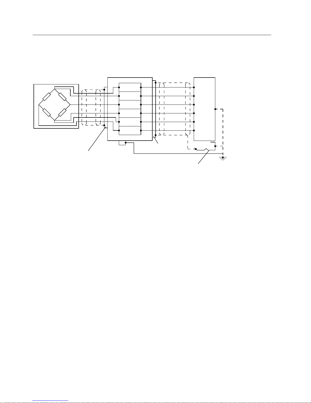
Load cells with six-wire system
1. Connect the load cells to the weighing module according to the circuit diagram.
&DEOHJODQG
&DEOHJODQG
6VKLHOGFRQQHFWLRQHOHPHQW
-XQFWLRQER[
6,:$5(;FDEOH
:HLJKLQJPRGXOH
%ODFN
*UD\
5HG
%OXH
*UHHQ
:KLWH
/RDGFHOO
3$/
EXC-
SENSE-
SIG-
EXC+
SENSE+
SIG+
SIG+
SENSE+
EXC+
SENSE-
EXC-
SIG-
Figure 5-2 Connecting principle for load cells with six-wire system
Page 15
Installing and connecting
5.4 Connection
SIWAREX JB stainless steel with ATEX certificate
Compact Operating Instructions, 06/2010, A5E01257284C-01
15
5.4 Connection
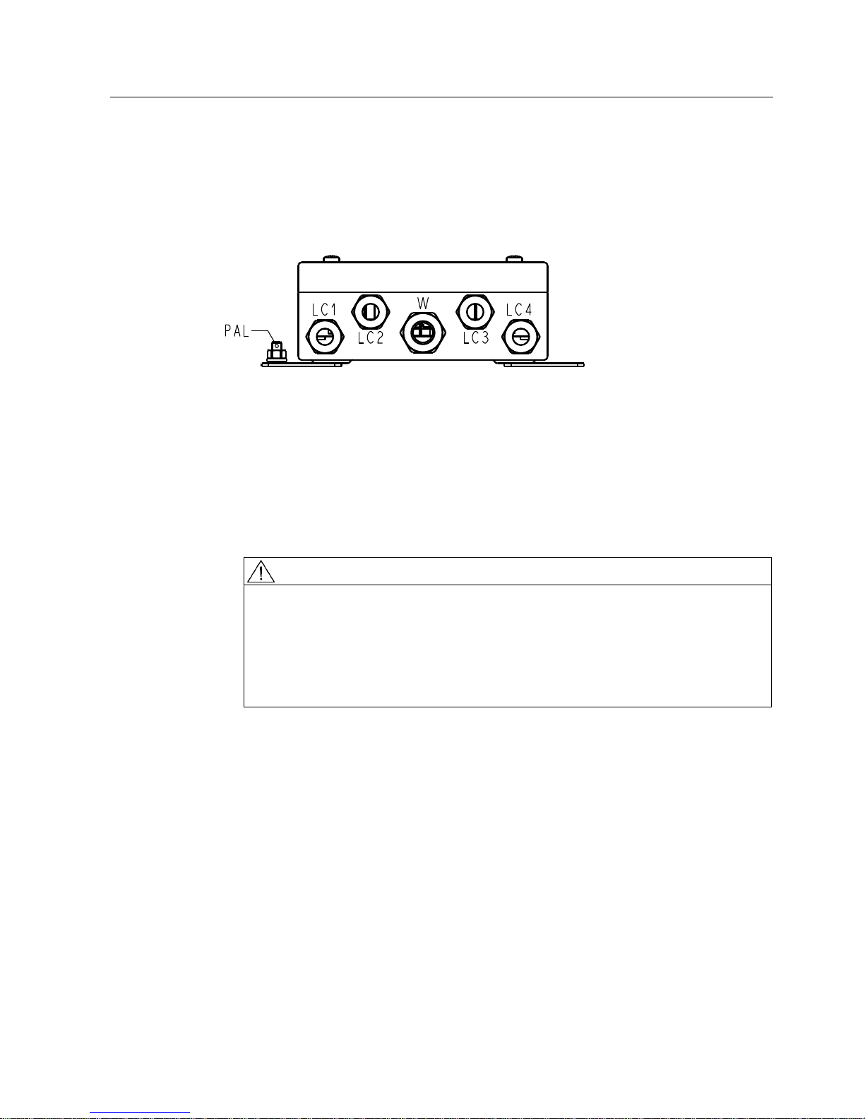
5.4.1 Installing the EMC cable glands and the screw plugs
LC Input for the connecting cable of a load cell
W Output to the weighing module or to the "Ex barrier"
PAL Equipotential bonding conductor
Figure 5-3 Assignment of the cable glands
1. Install an EMC cable gland for each load cell that is to be connected. The position of the
cable glands is shown in the figure above.
2. Open the cover of the junction box.
3. Close any unused openings in the SIWAREX JB enclosure using a cap screw.
WARNING
Measurement inaccuracies/risk of explosion
The cables must be matched to the cable glands.
If you use the provided M16x1.5 cable glands, only cables with a diameter of 7 to 12
mm may be laid into the device.
After installation, make sure that the cables are positioned securely and that the seals
are in the correct position.
Page 16
Installing and connecting
5.4 Connection
SIWAREX JB stainless steel with ATEX certificate
16 Compact Operating Instructions, 06/2010, A5E01257284C-01
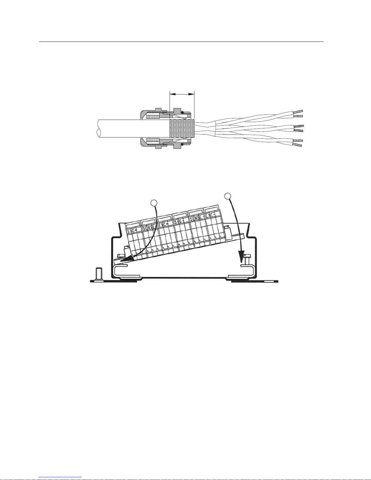
5.4.2 Connecting the shielding
1. Connect the cable shielding in the EMC cable glands so that it covers a broad area.
Figure 5-4 Connecting the shielding in the EMC cable gland
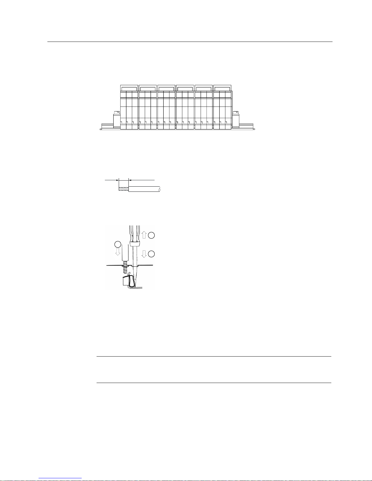
5.4.3 Installing the spring-loaded terminal block in the enclosure
Figure 5-5 Mounting the spring-loaded terminal block on the mounting rail
1. Tighten the two screws on the mounting rail by one turn each.
2. Slide the spring-loaded terminal block on one side under the applied screw
①.
3. Insert the spring-loaded terminal block
②.
4. Screw the spring-loaded terminal block firmly into place.
Page 17
Installing and connecting
5.4 Connection
SIWAREX JB stainless steel with ATEX certificate
Compact Operating Instructions, 06/2010, A5E01257284C-01
17
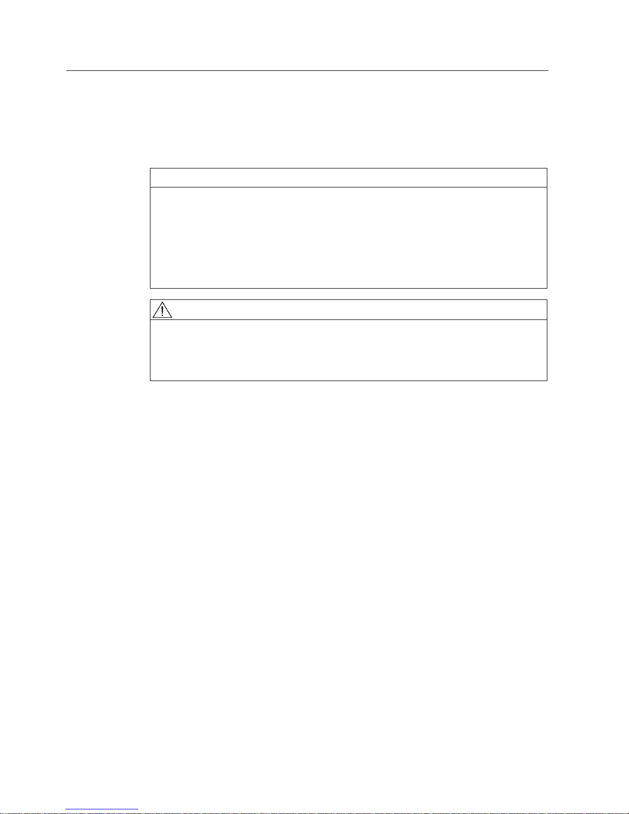
5.4.4 Connecting spring-loaded terminals
(;&6,* 6(16( 6(16(6,* (;&
Figure 5-6 Pin assignment of the spring-loaded terminals
In order to connect the spring-loaded terminals, you require a screwdriver with a maximum
blade width of 2.5 mm.
1. Strip the insulation from the cables as shown.
8 - 9 mm
Figure 5-7 Strip cable
2. Push the screwdriver into the rectangular opening ①.
This opens the spring clip of the spring-loaded terminal.
Figure 5-8 Connection of spring-loaded terminals
3. Insert the stripped wire into the round opening as far as the stop ②.
4. Remove the screwdriver from the rectangular opening
③.
The spring clip firmly holds the stripped wire and establishes the contact.
The use of spring-loaded terminals ensures that the contact pressure being exerted is
permanently maintained.
Note
The use of spring-loaded terminals ensures that the contact pressure being exerted is
permanently maintained.
Page 18
Installing and connecting
5.4 Connection
SIWAREX JB stainless steel with ATEX certificate
18 Compact Operating Instructions, 06/2010, A5E01257284C-01
5.4.5 Screwing on the cover
Requirements
CAUTION
Loss of degree of protection
Prior to closing the cover, check to ensure that:
• No dirt or cable residues are in the enclosure.
Such residues could lead to faults or short-circuits.
• The sealing surfaces are clean.
• The necessary cable glands are installed and screwed tightly in place.
• Unused openings are closed using the supplied screw plugs.
WARNING
Loss of degree of protection
Degree of protection IP66 is only guaranteed if the device was installed perfectly.
Please note that if the device is open or not completely closed, this degree of protection is
no longer guaranteed.
Procedure
1. Place the cover and screw it on properly.
Page 19

SIWAREX JB stainless steel with ATEX certificate
19 Compact Operating Instructions, 06/2010, A5E01257284C-01
Technical data
6
6.1 Ambient conditions
Ambient condition Value
Ambient temperature - 50 °C ... + 80 °C
Storage temperature - 50 °C ... + 100 °C
Type of protection: IP66, DIN 60529
6.2 Mechanical and electrical data
Variable Value
Enclosure dimensions See Dimension drawing (Page 21)
Enclosure material Stainless steel 1.4301
Weight Approx. 1.5 kg
Color Polished stainless steel
Electrical connection Spring-loaded terminals 1.5/1 mm2
Cable glands
• Load cells
• Signal cable
Screw connection
M16 x 1.5 mm
M20 x 1.5 mm
Terminal area
5 ... 7 mm
7 ... 12 mm
Vibration test of the terminals Acc. to DIN EN 60068-2-6: 1996-05
10 ... 150 ... 10 Hz, amplitude 0.35 mm
Variable Value
Rated voltage max. AC 250 V
Rated current max. 10 A per terminal
Conductor cross-section max. 1.5 mm²
Page 20

Technical data
6.3 Explosion protection
SIWAREX JB stainless steel with ATEX certificate
20 Compact Operating Instructions, 06/2010, A5E01257284C-01
6.3 Explosion protection
In hazardous areas, it is only permitted to use components with the appropriate Ex approval.
The junction box can be used in hazardous areas even for connecting an intrinsically safe
circuit according to EN 60079-14 or EN 61241-14.
In zone 20, certified circuits in category ia, ib or iaD, ibD are permitted.
The terminals meet the requirements for disconnecting intrinsically safe circuits: The
creepage distance and clearance are greater than 8 mm.
Only connect the device to circuits that comply with the technical data specified on the
nameplate or on the certificates and approvals (e.g., the EC-type examination certificates). If
the circuits do not comply with the information in the certificates and approvals, then the
safety required for the approval is longer guaranteed.
When using the junction box for type of protection nA, the junction box must be included in
the local potential equalization. The external and internal connection in the cover must be
used for this purpose. Use a cable eye that is crimped to the cable to do this. The minimum
cross-section of the PAL connecting cable must be the same or greater than the crosssection of the phase conductor. The washer that is also to be used must ensure that the
contact pressure is permanently maintained. The four cover screws must be screwed tight.
Before loosening the cover screws, all of the circuits must be de-energized.
The circuits that are connected must be either only intrinsically safe or only non-intrinsically
safe. Mixing is not allowed.
If the SIWAREX JB junction box is operated with the marking
II 1 D Ex tb + ib IIIC T85°C Da IP66 in hazardous zone 20, then the feeding circuit must
meet the requirements of protection type "intrinisically safe" Cat. ia or Cat. ib in connection
with another recognized protection type.
6.4 Electromagnetic compatibility
The SIWAREX JB junction box meets the following EMC requirements:
● EN 61326: 1999
● EN 45501: 1992
● NAMUR NE21: 2004
To maintain the electromagnetic compatibility, for example,
● ensure that the cables are routed with electromagnetic compatibility (even within
cabinets!).
● lay the signal cable segregated from cables with voltages > 60 V or high currents.
● avoid sites neighboring large electrical systems
Page 21
Technical data
6.5 Dimension drawing
SIWAREX JB stainless steel with ATEX certificate
Compact Operating Instructions, 06/2010, A5E01257284C-01
21
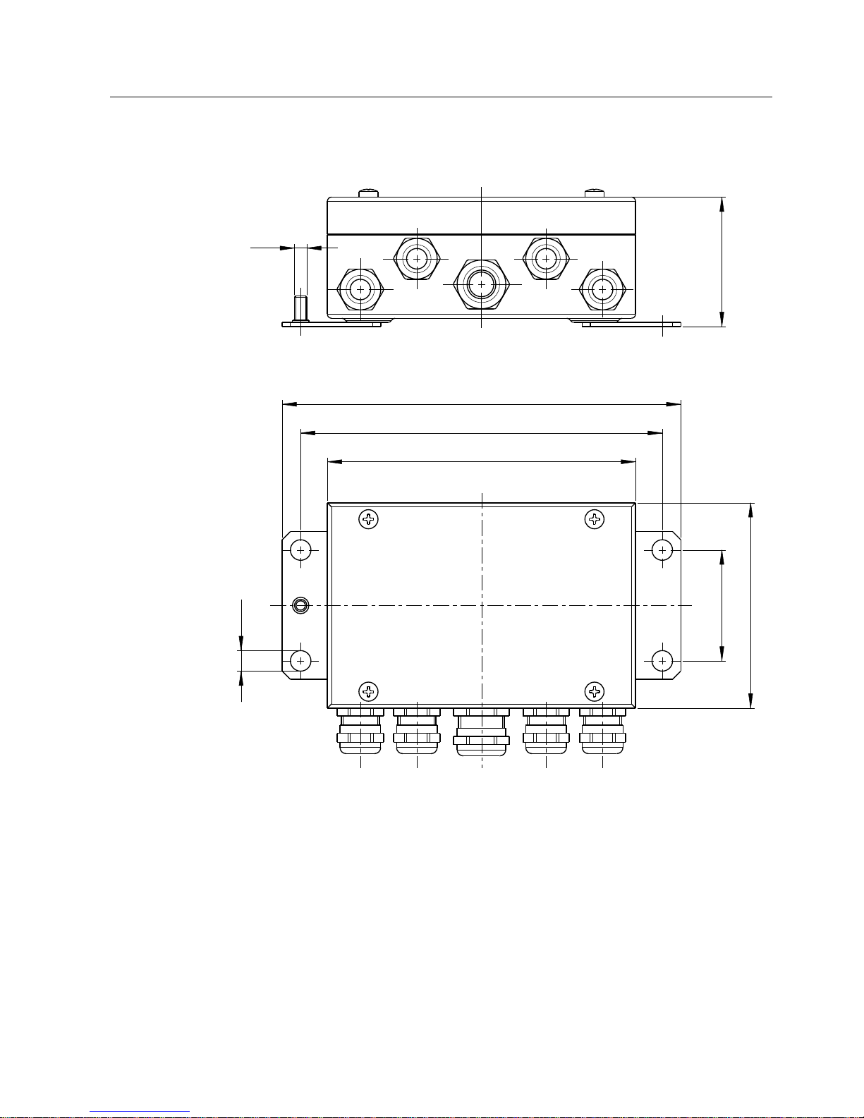
6.5 Dimension drawing
0
Figure 6-1 Dimension drawing
Page 22
SIWAREX JB stainless steel with ATEX certificate
Compact Operating Instructions, 06/2010, A5E01257284C-01
22
Ordering data
7
7.1 Order no.
Junction box
Designation Order no.
SIWAREX JB stainless steel with ATEX
certificate
7MH4710-1EA01
7.2 Accessories
EMC cable glands, stainless steel
Recommended suppliers:
RST Rabe-System-Technik und Vertriebs-GmbH
Otto-Lilienthal-Str. 19
49134 Wallenhorst
Germany
Phone: +45 (0) 54 07 / 87 66 – 0
Fax: +45 (0) 54 07 / 87 66 – 98
Internet: RST in the Internet (http://www.rst-gruppe.com
)
Signal cable
Recommended cable:
SIWAREX cable Li2Y2x0.75St+2x(2x0.34St)-CY
Application Sheath color Order no.
Standard applications Orange 7MH4702-8AG
Intrinsically safe Ex application Light blue 7MH4702-8AF
Page 23

SIWAREX JB stainless steel with ATEX certificate
23 Compact Operating Instructions, 06/2010, A5E01257284C-01
Appendix
A
A.1 Technical support
Technical Support
You can contact Technical Support for all IA and DT products:
● Via the Internet using the Support Request:
Support request (http://www.siemens.com/automation/support-request
)
● E-mail (mailto:[email protected]
)
● Phone: +49 (0) 180 5050 222
(0.14 €/min on German landlines, prices may vary for mobile systems)
● Fax: +49 (0) 180 5050 223
(0.14 €/min on German landlines, prices may vary for mobile systems)
Further information about our technical support is available in the Internet at
Technical Support (http://www.siemens.com/automation/csi/service
)
Service & Support on the Internet
In addition to our documentation, we offer a comprehensive knowledge base online on the
Internet at:
Services & Support (http://www.siemens.com/automation/se
rvice&support)
There you will find:
● The latest product information, FAQs, downloads, tips and tricks.
● Our newsletter, providing you with the latest information about your products.
● A Knowledge Manager to find the right documents for you.
● Our bulletin board, where users and specialists share their knowledge worldwide.
● You can find your local contact partner for Industry Automation and Drives Technologies
in our partner database.
● Information about field service, repairs, spare parts and lots more under "Services."
Additional Support
Please contact your local Siemens representative and offices if you have any questions
about the products described in this manual and do not find the right answers.
Find your contact partner at:
Partner (http://www.automation.siemens.com/partner
)
A signpost to the documentation of the various products and systems is available at:
Documentation (http://www.siemens.com/weighing/documentation
)
Page 24

Appendix
A.1 Technical support
SIWAREX JB stainless steel with ATEX certificate
24 Compact Operating Instructions, 06/2010, A5E01257284C-01
 Loading...