

Siemens SITRANS T Series,SITRANS TH300,SITRANS TH200 Operating Instructions Manual

SITRANS TH200/TH300
___________________
___________________
___________________
___________________
___________________
___________________
___________________
___________________
___________________
___________________
___________________
___________________
___________________
SITRANS T
Temperature transmitter
SITRANS TH200/TH300
Operating Instructions
7NG3211-1*N00 SITRANS TH200 7NG3212-0*N00
SITRANS TH300
08/2015
A5E00393069
Introduction
1
Safety information
2
Description
3
Installation
4
Connecting
5
Operation
6
Functional safety
7
Commissioning
8
Functions
9
Technical data
10
Dimension drawings
11
Spare parts and accessories
12
Appendix
A
-04

Siemens AG
Division Process Industries and Drives
Postfach 48 48
90026 NÜRNBERG
GERMANY
Order number: A5E00393069
Ⓟ
Copyright © Siemens AG 2015.
All rights reserved
Legal information
Warning notice system
DANGER
indicates that death or severe personal injury will result if proper precautions are not taken.
WARNING
indicates that death or severe personal injury may result if proper precautions are not taken.
CAUTION
indicates that minor personal injury can result if proper precautions are not taken.
NOTICE
indicates that property damage can result if proper precautions are not taken.
Qualified Personn el
personnel qualified
Proper use of Siemens products
WARNING
Siemens products may only be used for the applications described in the catalog and in the relevant technical
maintenance are required to ensure that the products operate safely and without any problems. The permissible
ambient conditions must be complied with. The information in the relevant documentation must be observed.
Trademarks
Disclaimer of Liability
This manual contains notices you have to observ e in order to ensure your personal safety, as well as to prevent
damage to property. The notices referring to your personal safety are highlighted in the manual by a safety alert
symbol, notices referring only to property damage have no safety alert symbol. These notices shown below are
graded according to the degree of danger.
If more than one degree of danger is present, the warning notice representing the highest degree of danger will
be used. A notice warning of injury to persons with a safety alert symbol may also include a warning relating to
property damage.
The product/system described in this documentation may be operated only by
task in accordance with the relevant documentation, in particular its warning notices and safety instructions.
Qualified personnel are those who, based on their training and experience, are capable of identifying risks and
avoiding potential hazards when working with these products/systems.
Note the following:
documentation. If products and components from other manufacturers are used, these must be recommended
or approved by Siemens. Proper transport, storage, installation, assembly, commissioning, operation and
All names identified by ® are registered trademarks of Siemens AG. The remaining trademarks in this publication
may be trademarks whose use by third parties for their own purposes could violate the rights of the owner.
We have reviewed the contents of this publication to ensure consistency with the hardware and software
described. Since variance cannot be precluded entirely, we cannot guarantee full consistency. However, the
information in this publication is reviewed regularly and any necessary corrections are included in subsequent
editions.
for the specific
09/2015 Subject to change

Table of contents
1 Introduction ............................................................................................................................................. 7
2 Safety information ................................................................................................................................. 11
3 Description ............................................................................................................................................ 13
4 Installation ............................................................................................................................................ 19
5 Connecting ........................................................................................................................................... 23
6 Operation .............................................................................................................................................. 29
7 Functional safety ................................................................................................................................... 33
1.1 Purpose of this documentation ................................................................................................. 7
1.2 History ....................................................................................................................................... 7
1.3 Notes on warranty ..................................................................................................................... 8
1.4 Laws and directives .................................................................................................................. 8
1.5 Conformity with European direc tives ........................................................................................ 8
3.1 Application .............................................................................................................................. 13
3.2 Product features ...................................................................................................................... 13
3.3 Nameplate structure ................................................................................................................ 14
3.4 Mode of operation ................................................................................................................... 15
3.5 Communication ....................................................................................................................... 16
3.5.1 Communication overview ........................................................................................................ 16
3.5.2 HART communication with supply from voltage source ......................................................... 16
3.5.3 HART communication with supply via isolating power supply ................................................ 17
4.1 Safety information ................................................................................................................... 19
4.2 Installation in the connection head ......................................................................................... 19
4.3 Installation on DIN rail and G rail ............................................................................................ 21
5.1 Safety information when connecting ....................................................................................... 24
5.1.1 Safety notes for connecting in hazardous TH200/300 ............................................................ 24
5.2 Connecting the auxiliary power supply ................................................................................... 26
5.3 Connection diagrams .............................................................................................................. 27
5.4 Notes on measuring current ................................................................................................... 28
6.1 Operation of the SITRANS TH200 .......................................................................................... 29
6.2 Operation of the SITRANS TH300 .......................................................................................... 30
6.2.1 Operation with the HART modem and SIMATIC PDM ........................................................... 30
6.2.2 Operation with HART communicator ...................................................................................... 31
7.1 Safety function ........................................................................................................................ 33
SITRANS TH200/TH300
Operating Instructions, 08/2015, A5E00393069-04
3

Table of contents
8 Commissioning ..................................................................................................................................... 41
9 Functions .............................................................................................................................................. 43
7.2 Safety-Instrumented system in single-channel operation (SIL 2) .......................................... 34
7.3 Safety-Instrumented system in multi-channel operation (SIL 3) ............................................ 34
7.4 Safety Integrity Level (SIL) ..................................................................................................... 35
7.5 Settings .................................................................................................................................. 37
7.6 Safety characteristics ............................................................................................................. 38
7.7 Maintenance/Checking .......................................................................................................... 39
8.1 LED operating indicator ......................................................................................................... 41
9.1 General information ............................................................................................................... 43
9.2 Broken wire monitoring .......................................................................................................... 44
9.3 Short-circuit monitoring .......................................................................................................... 45
9.4 Line compensation ................................................................................................................. 45
9.5 Type of characteristic curve (rising or falling) ........................................................................ 45
9.6 Measured value offset ............................................................................................................ 45
9.7 Sensor factor .......................................................................................................................... 46
9.8 Cold junction compensation with thermocouples ................................................................... 46
9.9 Calculation of differential value/mean value .......................................................................... 46
9.10 Electrical damping .................................................................................................................. 47
9.11 Current simulator function (only in SITRANS TH300) ........................................................... 47
9.12 Alarm current .......................................................................................................................... 47
9.13 Sensor calibration .................................................................................................................. 48
9.13.1 Sensor calibration (one point) ................................................................................................ 48
9.13.2 Sensor calibration (two point) ................................................................................................ 48
9.13.3 Trimming the lower sensor calibration (trim) point ................................................................. 49
9.13.4 Trimming the upper sensor trim point .................................................................................... 49
9.14 Current simulator calibration (digital-to-analog trim) .............................................................. 51
9.14.1 Function ................................................................................................................................. 51
9.14.2 Application example: Current input calibration at 4 mA and 20 mA ...................................... 51
9.15 Special characteristic curve ................................................................................................... 52
9.16 Factory parameters ................................................................................................................ 55
9.17 Diagnostics ............................................................................................................................. 56
9.17.1 Diagnostic functions ...............................................................................................................
9.
17.2 Violations of specification ....................................................................................................... 57
56
9.18 Runtime meters in temperature classes ................................................................................ 58
9.19 Slave pointer .......................................................................................................................... 59
9.20 Simulation (only in SITRANS TH300) .................................................................................... 60
9.21 Individual password protection (SITRANS TH300 only) ........................................................ 61
SITRANS TH200/TH300
4 Operating Instructions, 08/2015, A5E00393069-04

Table of contents
10 Technical data ...................................................................................................................................... 65
11 Dimension drawings .............................................................................................................................. 73
12 Spare parts and accessories ................................................................................................................. 75
A Appendix............................................................................................................................................... 77
Index..................................................................................................................................................... 81
10.1 Technical data ......................................................................................................................... 65
10.2 Digital measuring error............................................................................................................ 71
11.1 Dimension drawing for SITRANS TH200/TH300 .................................................................... 73
11.2 Dimension drawing for the DIN rail adapter ............................................................................ 73
A.1 Certificate ................................................................................................................................ 77
A.2 Control drawing ....................................................................................................................... 77
A.3 Return procedure .................................................................................................................... 79
A.4 Disposal .................................................................................................................................. 79
A.5 Technical support .................................................................................................................... 79
SITRANS TH200/TH300
Operating Instructions, 08/2015, A5E00393069-04
5

Table of contents
SITRANS TH200/TH300
6 Operating Instructions, 08/2015, A5E00393069-04

1
1.1
Purpose of this documentation
1.2
History
Edition
Firmware identifier
nameplate
System integration
Installation path for PDM
03/2008
Rev. 1.00
DD Rev. 1.01.06
Edition
Remark
06/2006
First edition
03/2008
Revision of content and layout
08/2015
Chapter "Functional Safety" updated
These instructions contain all information required to commission and use the device. Read
the instructions carefully prior to installation and commissioning. In order to use the device
correctly, first review its principle of operation.
The instructions are aimed at persons mechanically installing the device, connecting it
electronically, configuring the parameters and commissioning it, as well as service and
maintenance engineers.
This history establishes the correlation between the current documentation and the valid
firmware of the device.
The documentation of this edition is applicable for the following firmware:
06/2006 FW: 01.01.02
HW: 01.00
FW: 01.01.04
06/2010
08/2015 FW: 01.01.04
The most important changes in the documentation when compared with the respective
previous edition are given in the following table.
HW: 01.02
HW: 01.02
TH200: SIPROM T V1.07
TH300: PDM V6.0DD
Rev. 1.00
TH200: SIPROM T V1.2.1
TH300: PDM V6.0DD
TH200:
SIPROM T V1.2.3
TH300:
PDM V8.X
TH200: not relevant
TH300: SITRANS TH300
TH200: not relevant
TH300: SITRANS TH300
TH200:
Not relevant
TH300:
SITRANS TH300
SITRANS TH200/TH300
Operating Instructions, 08/2015, A5E00393069-04
7

Introduction
1.3
Notes on warranty
1.4
Laws and directives
1.5
Conformity with European directives
Electromagnetic compatib
i
2004/108/EC
Directive of the European Parliament and of the Council on the
approximation of the laws of the Member States relating to electromagnetic compatibility and repealing Directive 89/336/EEC.
Low voltage directive LVD
2006/95/EC
Directive of the European Parliament and of the Council on the
harmonisation of the laws of Member States relating to electr
cal equipment designed for use within certain voltage limits.
Atmosphère explosible
ATEX
94/9/EC
Directive of the European Parliament and the Council on the
approximation of the laws of the Member States concerning
equipment and protective systems intended for use in potent
ly explosive atmospheres.
2006/95/EC LVD
Directive of the European Parliament and of the Council on the
harmonisation of the laws of Member States relating to electr
cal equipment designed for use within certain voltage limits.
Pressure equipment d
rect
97/23/EC
Directive of the European Parliament and of the Council on the
approximation of the laws of the Member States concerning
pressure equipment.
1.3 Notes on warranty
The contents of this manual shall not become part of or modify any prior or existing
agreement, commitment or legal relationship. The sales contract contains all obligations on
the part of Siemens as well as the complete and solely applicable warranty conditions. Any
statements regarding device versions described in the manual do not create new war ranti es
or modify the existing warranty.
The content reflects the technical status at the time of publishing. Siemens reserves the right
to make technical changes in the course of further development.
Observe the test certification, provisions and laws applicable in your country during
connection, assembly and operation. These include, for example:
● National Electrical Code (NEC - NFPA 70) (USA)
● Canadian Electrical Code (CEC) (Canada)
Further provisions for hazardous area applications are for example:
● IEC 60079-14 (international)
● EN 60079-14 (EC)
The CE marking on the device symbolizes the conformity with the following European
directives:
il-
ty EMC
i-
ial-
i-
i-
ive PED
SITRANS TH200/TH300
8 Operating Instructions, 08/2015, A5E00393069-04

Introduction
Radio and telecommunic
tions terminal equipment
R&TTE
1999/5/EC
Directive of the European Parliament and of the
radio equipment and telecommunications terminal equipment
and the mutual recognition of their conformity.
Measuring instruments d
rective MID
2004/22/EC
Directive of the European Parliament and the advis
harmonization of measuring instruments.
Non
instruments
90/384/EEC
Directive of the European Parliament and of the Council on the
approximation of the laws of the Member States concerning
non-automatic weighing instruments.
1.5 Conformity with European directives
a-
i-
Council on
ory body for
-automatic weighing
The applicable directives can be found in the EC conformity declaration of the specific
device.
SITRANS TH200/TH300
Operating Instructions, 08/2015, A5E00393069-04
9

Introduction
1.5 Conformity with European directives
SITRANS TH200/TH300
10 Operating Instructions, 08/2015, A5E00393069-04

2
WARNING
Improper device modifications
Qualified personne l for hazardous area applications
WARNING
Unsuitable devic e for the hazardous area
This device left the factory in good working condition. In order to maintain this status and to
ensure safe operation of the device, observe these instructions and all the specifications
relevant to safety.
Observe the information and symbols on the device. Do not remove any information or
symbols from the device. Always keep the information and symbols in a completely legible
state.
Danger to personnel, system and environment can result from modifications to the device,
particularly in hazardous areas.
• Only carry out modifications that are described in the instructions for the device. Failure
to observe this requirement cancels the manufacturer's warranty and the product
approvals.
Persons who install, connect, commission, operate, and service the device in a hazardous
area must have the following specific qualifications:
● They are authorized, trained or instructed in operating and maintaining devices and
systems according to the safety regulations for electrical circuits, high pressures,
aggressive, and hazardous media.
● They are authorized, trained, or instructed in carrying out work on electrical circuits for
hazardous systems.
● They are trained or instructed in maintenance and use of appropriate safety equipment
according to the pertinent safety regulations.
Danger of explosion.
• Only use equipment that is approved for use in the intended hazardous area and
labelled accordingly.
SITRANS TH200/TH300
Operating Instructions, 08/2015, A5E00393069-04
11
Safety information
WARNING
Loss of safety of device with type of protection "Intrinsic safety Ex i"
se
WARNING
Incorrect selection of type of protection
CAUTION
Device damage due to electrical discharge
If the device has already been operated in non-intrinsically safe circuits or the electrical
specifications have not been observed, the safety of the device is no longer ensured for u
in hazardous areas. There is a danger of explosion.
• Connect the device with type of protection "Intrinsic safety" solely to an intrinsically safe
circuit.
• Observe the specifications for the electrical data on the certificate and/or in Chapter
"Technical data".
Danger of explosion in areas subject to explosion hazard.
This device is approved for several types of protection.
1. Decide in favor of one type of protection.
2. Connect the device in accordance with the selected type of protection.
3. In order to avoid incorrect use at a later point, make the types of protection that are not
used permanently unrecognizable on the nameplate.
• Avoid contact with the device or electrical connections without being electrostatically
discharged
SITRANS TH200/TH300
12 Operating Instructions, 08/2015, A5E00393069-04

3
3.1
Application
3.2
Product features
SITRANS TH200 and SITRANS TH300 transmitters can be used in all industries. Their
compact size means that they can be installed in connection heads of type B, in accordance
with DIN43729, or larger. Their input stage means that the following sensor and signal
sources can be connected:
● Resistance thermometer
● Thermocouples
● Resistance-type transmitter/potentiometer
● DC voltage sources
The output signal is an output current of 4 to 20 mA that corresponds to the sensor
characteristic curve.
Explosion-proof transmitters can be installed and operated within potentially explosive
atmospheres in compliance with the information given in the relevant certificates and
approvals and in these Operating Instructions.
The transmitters SITRANS T200-TF / T300-TF and SITRANS T200-TR / T300-TR are parts
of the separately certified devices SITRANS TF (7NG313.-*****) and SITRANS TR200 /
TR300 (7NG303.-*****). Further information is given in the specific product manuals or
product certificates.
● Transmitter with two-wire technology
● Installation in connection heads of type B, in accordance with DIN 43729 or larger, or on
a DIN rail
● With communications capability via the HART protocol rev. 5.9 in SITRANS TH300 or via
a proprietary protocol in SITRANS TH200. This enables, for example, the sensor
activation and measuring range to be programmed.
● Galvanic isolation
● Intrinsically-safe and non-sparking version for use in hazardous areas.
● Two additional test pins for connecting a multimeter make it possible to measure the
current signal without interrupting the current loop.
● Indication of operating status: LED green, flashing red, or red
● Special characteristic curve
● Diagnostic functions in SITRANS TH300: Min/max pointer, runtime meter, simulation
SITRANS TH200/TH300
Operating Instructions, 08/2015, A5E00393069-04
13
Description
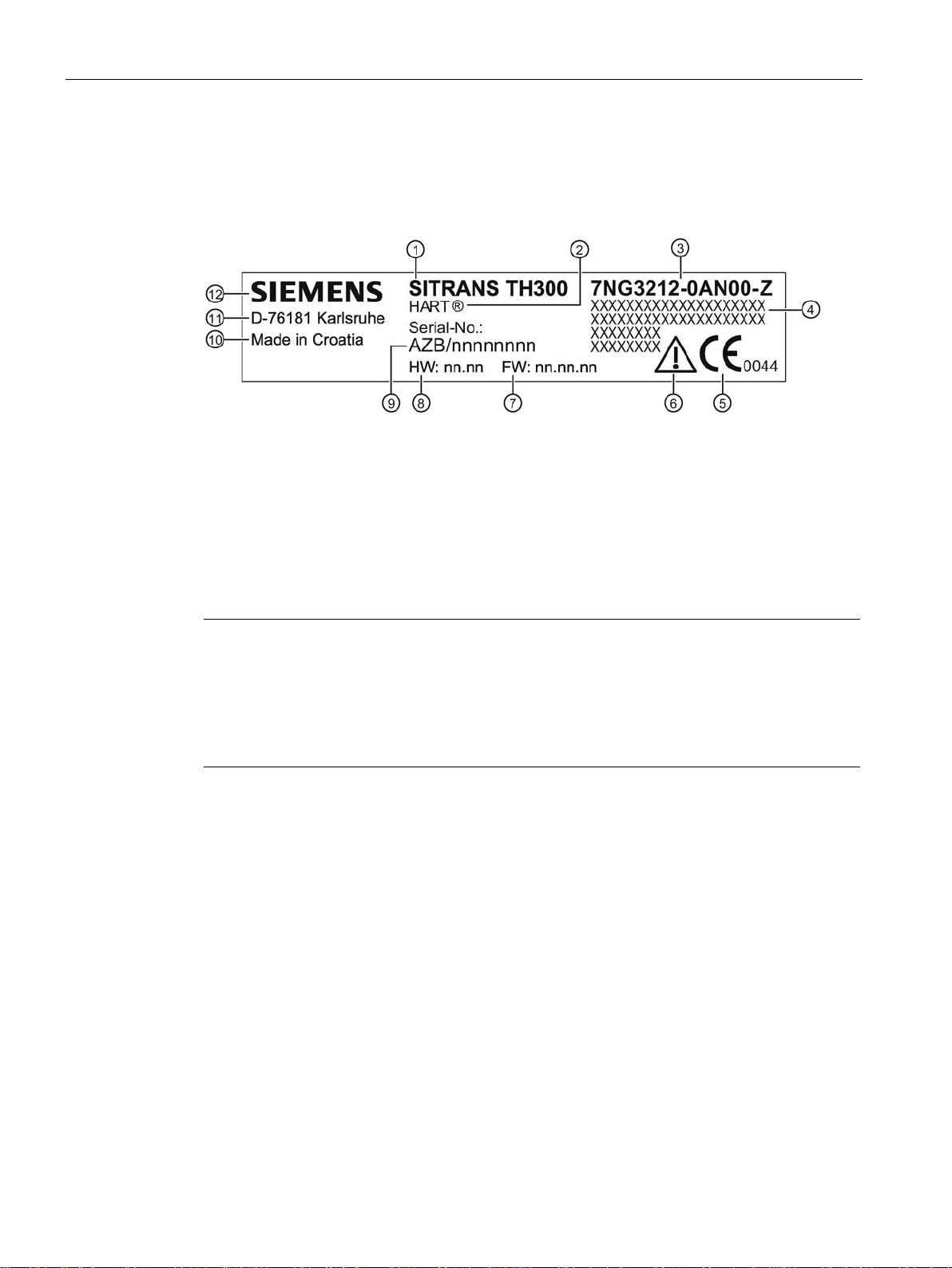
3.3
Nameplate structure
①
Product name
②
Version
③
Order No.
④
Additional data
⑤
CE mark
⑥
Pay attention to the Operating Instructions
⑦
Firmware revision
⑧
Hardware revision
⑨
Serial number
⑩
Place of manufacture
⑪
Manufacturer's address
⑫
Manufacturer
Note
Information about explosion protection
With explosion
additional plate on the enclosure.
Information regarding the certified types of protection can be found in Chapter
data
3.3 Nameplate structure
The nameplate is located on the enclosure and carries the Order No. and other important
product information; see following example.
Figure 3-1 Layout of the nameplate, SITRANS TR300 as example
-proof devices, the information about explosion protection is noted on an
Technical
(Page 65):
SITRANS TH200/TH300
14 Operating Instructions, 08/2015, A5E00393069-04
Description
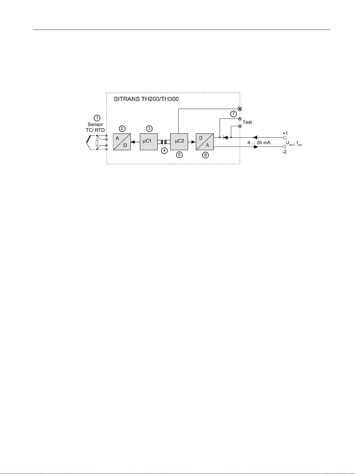
3.4
Mode of operation
①
millivolt transmitter
②
Analog-to-digital converter
③
Microcontroller secondary side
④
Galvanic isolation
⑤
Microcontroller primary side
⑥
Digital-to-analog converter
⑦
LED
U
aux
Auxiliary power supply
I
out
Output current
Test
Test terminals for brief connection of an ammeter
Mode of operation of the transmitter
3.4 Mode of operation
Based on the function block diagram, the mode of operation is described below.
Sensors such as the resi s tance thermometer, thermocouple, resistance-type transmitter,
Figure 3-2 Function block diagram for SITRANS TH200/TH300
● The sensor supplies an electrical signal ①.
● This signal is converted to a digital signal in an ana log -to-digital converter
● The digital signal is evaluated in a secondary-side microcontroller
accordance with the sensor characteristic.
● The digital signal is transferred to the primary-side microcontroller
isolation
● The analog output value is calculated in the prim ar y -side microcontroller
functional status is indicated by LED
● The digital-to-analog converter
20 mA.
● The source of auxiliary power supply is located in the output signal circuit.
④.
②.
③ and corrected in
⑤ via the galvanic
⑤. The
⑦, and the communications data are prepared.
⑥ then converts the signal into an output current of 4 to
SITRANS TH200/TH300
Operating Instructions, 08/2015, A5E00393069-04
15
Description
3.5
Communication
3.5.1
Communication overview
SITRANS TH200
SITRANS TH300
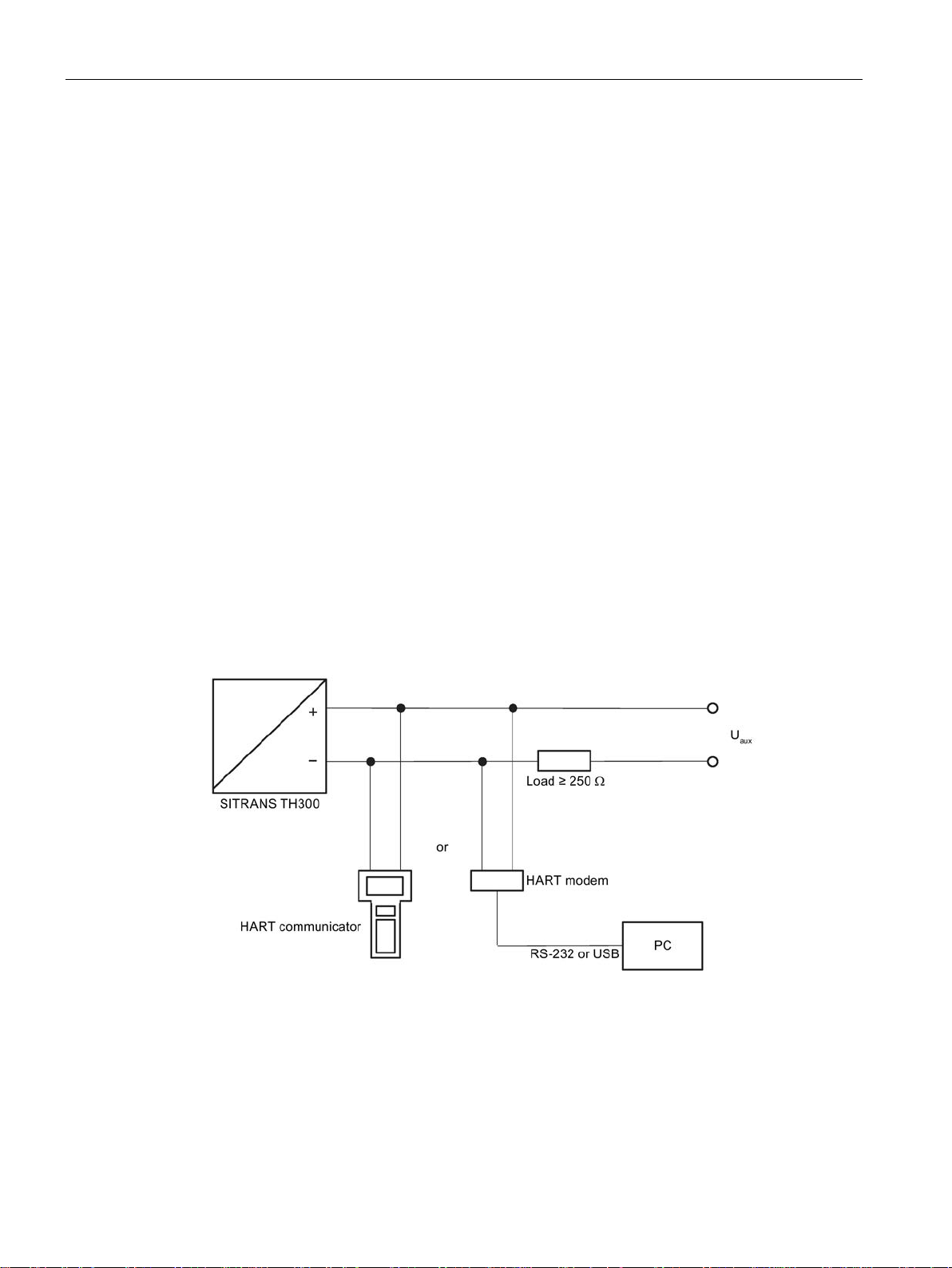
3.5.2
HART communication with supply from voltage source
3.5 Communication
Parameterization of the SITRANS TH200 is only possi ble off lin e. A conf igur ati on produc e d
offline on a PC using SIPROM T is transferred to the transmitter via the SIPROM T modem.
SITRANS TH200 does not have a HART interface.
SITRANS TH300 is parameterized online. The transmitter uses the HART protocol for this,
and communicates with the following external devices via its HART interface:
● HART communicator
● HART modem to the connected PG/PC with SIMATIC PDM
Both devices provide direct online access to all transmitter functions and parameters.
Figure 3-3 HART communication with supply from voltage source
SITRANS TH200/TH300
16 Operating Instructions, 08/2015, A5E00393069-04
Description
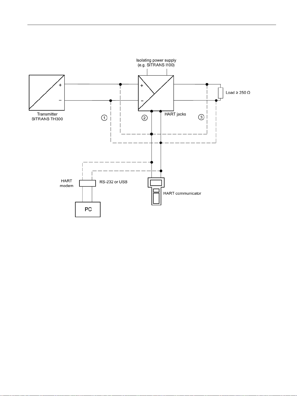
3.5.3
HART communication with supply via isolating power supply
①
supply.
②
HART communication via HART jacks of isolating power supply
③
sions ① or ②
3.5 Communication
Only intrinsically safe HART communicators or HART modems are allowed to be used with an intrinsically safe power
Load ≥ 250 Ω only relevant if HART communication takes place via this branch. Otherwise, load of 0 to 650 Ω for ver-
Figure 3-4 HART communication with supply via isolating power supply
SITRANS TH200/TH300
Operating Instructions, 08/2015, A5E00393069-04
17

Description
3.5 Communication
SITRANS TH200/TH300
18 Operating Instructions, 08/2015, A5E00393069-04

4
4.1
Safety information
WARNING
Mounting in hazardous ar eas
WARNING
Exceeded maximum ambient or process media temperature
4.2
Installation in the connection head
Note
The transmitter is only designed for insta
Make sure you observe the following information before installing the transmitter:
• Install the transmitter in an enclosure appropriate for the envisaged application
• In hazardous areas, also observe the requirements specified in the Ex certificates and
approvals.
Danger of explosion in hazardous areas.
Device damage.
• Make sure that the maximum permissible ambient and process media temperatures of
the device are not exceeded. Refer to the information in Chapter "Auto-Hotspot".
llation in a type B connection head or larger.
The transmitter is either secured in the base of the connection head or in the raised cover of
the connection head.
Included in the transmitter's scope of delivery are:
● Springs
● Fixing screws
● Lock washers for installation on the round plate (TH200/TH300 only)
SITRANS TH200/TH300
Operating Instructions, 08/2015, A5E00393069-04
19
Installation
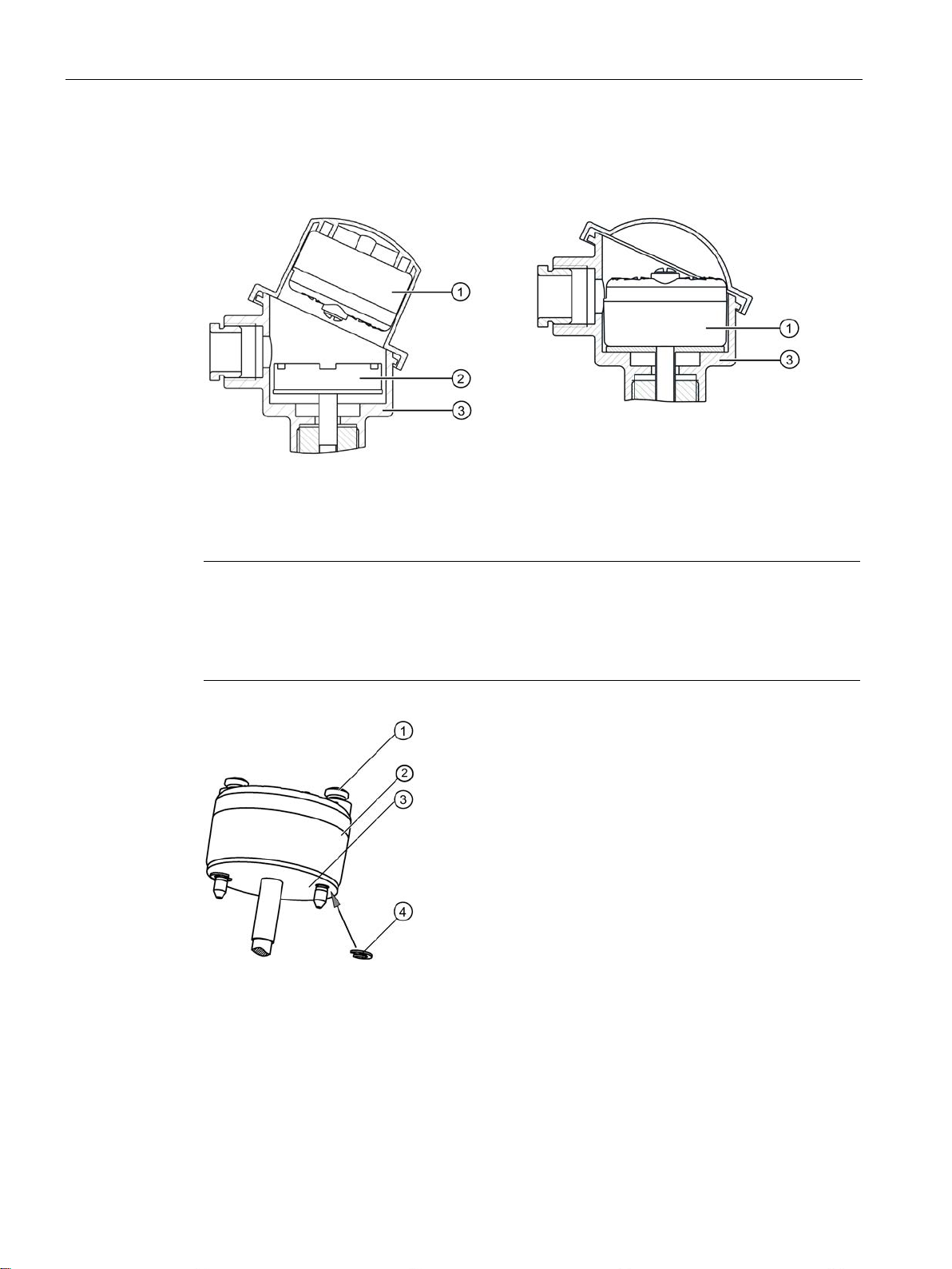
Securing the transmitter
in the connection head cover
in the connection head base
①
Transmitter
②
Ceramic base of the measuring el
③
Connection head
Note
Using the lock washers (TH200/TH300 only)
The lock washers
transmitter when the transmitter
temperature probe.
①
Fixing screw M4x35
②
Transmitter
③
Round plate
④
Lock washer DIN 6799 - 3.2 A2
4.2 Installation in the connection head
:
ement
④ included in the delivery are only required for securely fastening the
② is directly installed on the round plate ③ for a
SITRANS TH200/TH300
20 Operating Instructions, 08/2015, A5E00393069-04
Installation
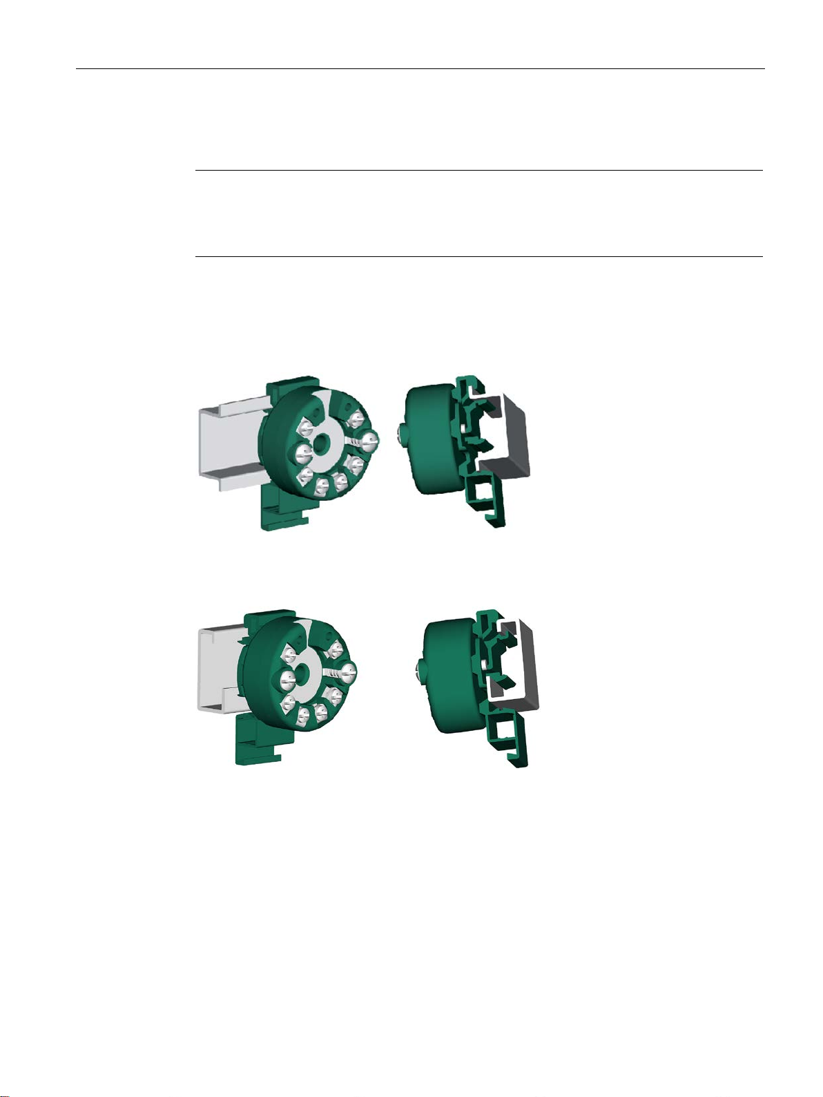
4.3
Installation on DIN rail and G rail
Note
Fixing rings
The fixing rings included in the scope of delivery for the transmitter are not required for the
installation on DIN rails or G rails.
4.3 Installation on DIN rail and G rail
You can either install the transmitter on a 35 mm DIN rail or on a 32 mm G rail.
DIN EN 60715 applies to DIN rails and G rails in this context. The DIN rail adapter required
for installation can be ordered as an accessory under the Order No. 7NG3092-8KA.
Adhere to the ambient conditions specified in the technical data.
Figure 4-1 Securing the transmitter on DIN rails
Figure 4-2 Securing the transmitter on G rails
SITRANS TH200/TH300
Operating Instructions, 08/2015, A5E00393069-04
21

Installation
4.3 Installation on DIN rail and G rail
SITRANS TH200/TH300
22 Operating Instructions, 08/2015, A5E00393069-04

5
WARNING
Connecting device in energized state
Exceptions
Note
Improvement of interference immunity
•
•
•
•
NOTICE
Ambient temperature too high
Danger of explosion in hazardous areas.
• Connect devices in hazardous areas only in a de-energized state.
:
• Circuits of limited energy may also be connected in the energized state in hazardous
areas.
• Exceptions for type of protection "Non-sparking nA" (Zone 2) are regulated in the
relevant certificate
Lay signal cables separate from cables with voltages > 60 V.
Use cables with twisted wires.
Keep device and cables distant to strong electromagnetic fields.
Use cables with wires that have a maximum cross-sectional area of 2.5 mm2.
Damage to cable sheath.
• At an ambient temperature ≥ 60 °C (140 °F), use heat-resistant cables suitable for an
ambient temperature at least 20 °C (36 °F) hig her .
SITRANS TH200/TH300
Operating Instructions, 08/2015, A5E00393069-04
23

Connecting
5.1
Safety information when connecting
WARNING
Improper power supply
5.1.1
Safety notes for connecting in hazardous TH200/300
Zone 0, 1, 2 in type of protection "ia/ib/ic" - intrinsic safety
Maximum values of the auxiliary power supply and signal circuits:
Ui = 30 V DC
Ii = 100 mA
Pi = 750 mW
Li = 104 μH
Ci = 11 nF
Maximum values of the sensor c i rcuit for Ex ia:
U0= 6 V DC:
I0 = 25 mA
P0 = 37 mW
L0 [mH]
50
10 1 0.1
C0 [μF]
1
1.6
2.6
4.8
5.1 Safety information when connecting
Danger of explosion in hazardous areas as result of incorrect power supply, e.g. using
direct current instead of alternating current.
• Connect the device in accordance with the specified power supply and signal circuits.
The relevant specifications can be found in the certificates, in Chapter "Technical data
(Page 65)" or on the nameplate.
The 4 to 20 mA input and sensor circuits are electrically isolated and have been tested with a
voltage of 1.5 kV DC/1 minute.
The sensor circuit is reliably galvanically isolated from the auxiliary power supply and signal
circuit, up to a peak value of the rated voltage of 60 V. Be sure to observe the construction
directives valid at the construction location for electrical resources in hazardous areas. In
Europe, this is the standard EN 60079-14.
● Only connect the transmitter, in accordance with the certificate of compliance, to devices
certified as intrinsically-safe.
● If the connection head is made of aluminum, the requirements of EN 60079-26, section
4.3.3, must be observed for uses where the device category 1 G is required.
● The transmitter must be mounted in an enclosure in order to provide a degree of
protection of at least IP20 according to EN60529
SITRANS TH200/TH300
24 Operating Instructions, 08/2015, A5E00393069-04
Connecting
Zone 2 in type of protection "nA" - non-sparking resources
Maximum values of the sensor c i rcuit:
U0= 6 V DC:
I0 = 25 mA
P0 = 37 mW
L0 [mH]
50
10 1 0.1
C0 [μF]
1
1.6
2.6
4.8
Additional requirements for use in dust explosion protected areas
WARNING
Limited range of use
5.1 Safety information when connecting
● Install the transmitter in an enclosure meeting the degree of protection IP54 per EN
60529, e.g. in a type B connection head per DIN 43729.
● Adhere to the conditions for installers applicable to this type of protection.
● The maximum approved input voltage is U
= 32 V DC.
n
● Take measures to ensure that the supply voltage (including transients) does not rise
above 140 % of the rated voltage.
Install the transmitter in an enclosure suitable for the respective type of dust and
corresponding Zone in accordance with the inspection certificate valid in your country. The
enclosure shall have at least IP5x protection in accordance with IEC 60529.
If the device has been operated outside the ambient conditions specified for potentially
explosive atmospheres, you may no longer operate the device in potentially explosive
atmospheres. Make sure to permanently mask all Ex markings on the nameplate.
SITRANS TH200/TH300
Operating Instructions, 08/2015, A5E00393069-04
25
 Loading...