

Siemens SITRANS TS100, SITRANS TSthermowell, SITRANS TS200, SITRANS TS300, SITRANS TS500 Compact Operating Instructions
...Page 1

___________________
___________________
___________________
___________________
___________________
___________________
___________________
___________________
___________________
___________________
SITRANS
Temperature sensors TS100/TS200/TS300/TS500/TSinse rt/TSthermowell
Compact Operating Instructions
01/2018
A5E03920348
Introduction
1
Safety notes
2
Description
3
Installing
4
Connecting
5
Commissioning
6
Service and maintenance
7
Technical data
8
Dimension drawings
9
Appendix
A
-AE
Page 2

Siemens AG
Division Process Industries and Drives
Postfach 48 48
90026 NÜRNBERG
GERMANY
Document order number: A5E03920348
Ⓟ
Copyright © Siemens AG 2018.
All rights reserved
Legal information
Warning notice system
DANGER
indicates that death or severe personal injury will result if proper precautions are not taken.
WARNING
indicates that death or severe personal injury may result if proper precautions are not taken.
CAUTION
indicates that minor personal injury can result if proper precautions are not taken.
NOTICE
indicates that property damage can result if proper precautions are not taken.
Qualified Personnel
personnel qualified
Proper use of Siemens products
WARNING
Siemens products may only be used for the applications described in the catalog and in the relevant technical
ambient conditions must be complied with. The information in the relevant documentation must be observed.
Trademarks
Disclaimer of Liability
This manual contains notices you have to observe in order to ensure your personal safety, as well as to prevent
damage to property. The notices referring to your personal safety are highlighted in the manual by a safety alert
symbol, notices referring only to property damage have no safety alert symbol. These notices shown below are
graded according to the degree of danger.
If more than one degree of danger is present, the warning notice representing the highest degree of danger will
be used. A notice warning of injury to persons with a safety alert symbol may also include a warning relating to
property damage.
The product/system described in this documentation may be operated only by
task in accordance with the relevant documentation, in particular its warning notices and safety instructions.
Qualified personnel are those who, based on their training and experience, are capable of identifying risks and
avoiding potential hazards when working with these products/systems.
Note the following:
documentation. If products and components from other manufacturers are used, these must be recommended
or approved by Siemens. Proper transport, storage, installation, assembly, commissioning, operation and
maintenance are required to ensure that the products operate safely and without any problems. The permissible
All names identified by ® are registered trademarks of Siemens AG. The remaining trademarks in this publication
may be trademarks whose use by third parties for their own purposes could violate the rights of the owner.
We have reviewed the contents of this publication to ensure consistency with the hardware and software
described. Since variance cannot be precluded entirely, we cannot guarantee full consistency. However, the
information in this publication is reviewed regularly and any necessary corrections are included in subsequent
editions.
for the specific
03/2018 Subject to change
Page 3

Table of contents
1 Introduction ............................................................................................................................................. 7
2 Safety notes .......................................................................................................................................... 11
3 Description ............................................................................................................................................ 17
4 Installing ............................................................................................................................................... 23
1.1 Purpose of this documentation ................................................................................................. 7
1.2 Scope of this documentation .................................................................................................... 7
1.3 Document history ...................................................................................................................... 8
1.4 Checking the consignment ....................................................................................................... 8
1.5 Security information .................................................................................................................. 9
1.6 Transportation and storage ....................................................................................................... 9
1.7 Notes on warranty ................................................................................................................... 10
2.1 Preconditions for use .............................................................................................................. 11
2.1.1 Laws and directives ................................................................................................................ 11
2.1.2 Conformity with European directives ...................................................................................... 12
2.2 Improper device modifications ................................................................................................ 12
2.3 Requirements for special applications .................................................................................... 13
2.4 Use in hazardous areas .......................................................................................................... 13
2.4.1 Qualified personnel for hazardous area applications ............................................................. 13
2.5 Use in flameproof enclosures "d" and protection in enclosures "tb" ....................................... 14
2.5.1 For SITRANS TS500 .............................................................................................................. 15
2.5.2 For SITRANS TSinsert/TS100/TS200/TS500 ........................................................................ 16
3.1 Overview ................................................................................................................................. 17
3.2 Application .............................................................................................................................. 18
3.3 Functional principles ............................................................................................................... 18
3.4 Nameplate structure ................................................................................................................ 18
3.5 Temperature transmitter for SITRANS TS500 ........................................................................ 19
3.6 Measuring inserts for SITRANS TS500 .................................................................................. 20
3.7 Connection heads for SITRANS TS500 ................................................................................. 21
4.1 Basic safety notes ................................................................................................................... 23
4.1.1 Installation and location requirements .................................................................................... 24
4.1.2 Proper mounting ..................................................................................................................... 25
4.2 Install ....................................................................................................................................... 27
4.3 Install SITRANS TS300 Clamp-on .......................................................................................... 29
TS100/TS200/TS300/TS500/TSinsert/TSthermowell
Compact Operating Instructions, 01/2018, A5E03920348-AE
3
Page 4

Table of contents
5 Connecting ........................................................................................................................................... 31
6 Commissioning ..................................................................................................................................... 39
7 Service and maintenance ...................................................................................................................... 41
8 Technical data ...................................................................................................................................... 45
9 Dimension drawings .............................................................................................................................. 65
4.4 Disassembly ........................................................................................................................... 30
5.1 Basic safety notes .................................................................................................................. 31
5.1.1 For SITRANS TSinsert ........................................................................................................... 34
5.1.2 For SITRANS TSinsert/TS100/TS200/TS500 ........................................................................ 34
5.1.3 For SITRANS TS100/TS200 .................................................................................................. 34
5.1.4 For SITRANS TS500 ............................................................................................................. 35
5.2 Electrical connection .............................................................................................................. 35
5.3 Electrical connection of resistance thermometers ................................................................. 36
5.4 Electrical connection of thermocouples ................................................................................. 37
5.5 Electrical connection of connectors ....................................................................................... 37
6.1 Basic safety notes .................................................................................................................. 39
6.2 Commissioning....................................................................................................................... 40
7.1 Cleaning ................................................................................................................................. 43
7.2 Return procedure ................................................................................................................... 43
7.3 Disposal ................................................................................................................................. 44
8.1 Rated conditions .................................................................................................................... 45
8.1.1 Maximum permissible ambient temperatures in the connection area of the sensor ............. 45
8.1.1.1 General limitations for compression fittings ........................................................................... 45
8.1.1.2 SITRANS TS100 .................................................................................................................... 46
8.1.1.3 SITRANS TS500 .................................................................................................................... 47
8.1.2 Maximum permitted sample temperatures within the process .............................................. 54
8.1.3 Measuring range .................................................................................................................... 56
8.2 Construction ........................................................................................................................... 56
8.3 Electrical data ......................................................................................................................... 57
8.4 Measuring tolerances for resistance thermometers ............................................................... 58
8.5 Measuring accuracy for thermocouples ................................................................................. 59
8.6 Certificates and approvals ..................................................................................................... 60
8.6.1 SITRANS TSInsert/TS100/TS200/TS500 .............................................................................. 60
8.6.2 SITRANS TS500 .................................................................................................................... 62
9.1 Overview ................................................................................................................................ 65
9.2 SITRANS TS100 .................................................................................................................... 69
9.3 SITRANS TS200 .................................................................................................................... 70
9.4 SITRANS TS300 .................................................................................................................... 71
9.5 SITRANS TS500 .................................................................................................................... 75
TS100/TS200/TS300/TS500/TSinsert/TSthermowell
4 Compact Operating Instructions, 01/2018, A5E03920348-AE
Page 5

Table of contents
A Appendix............................................................................................................................................. 107
Index................................................................................................................................................... 109
9.5.1 SITRANS TS500, types 2 and 2N .......................................................................................... 75
9.5.2 SITRANS TS500, types 2G and 2F ........................................................................................ 76
9.5.3 SITRANS TS500, type 3 ......................................................................................................... 77
9.5.4 SITRANS TS500, types 3G and 3F ........................................................................................ 78
9.5.5 SITRANS TS500, types 4 and 4F ........................................................................................... 79
9.5.6 SITRANS TS500, type ST, threaded tapered well (7MC65..) ................................................ 81
9.5.7 SITRANS TS500, type SST, threaded tapered well (7MC55..) .............................................. 82
9.5.8 SITRANS TS500, type SS, threaded straight well (7MC65..)................................................. 84
9.5.9 SITRANS TS500, type SS, threaded straight well (7MC55..)................................................. 85
9.5.10 SITRANS TS500, type SR, threaded reduced well (7MC65..) ............................................... 86
9.5.11 SITRANS TS500, type SR, threaded reduced well (7MC55..) ............................................... 87
9.5.12 SITRANS TS500, type FT, flanged tapered well (7MC65..) ................................................... 88
9.5.13 SITRANS TS500, type FST, flanged tapered well (7MC55..)................................................. 89
9.5.14 SITRANS TS500, type FS, flanged straight well (7MC65..) ................................................... 91
9.5.15 SITRANS TS500, type FS, flanged straight well (7MC55..) ................................................... 92
9.5.16 SITRANS TS500, type FR, flanged reduced well (7MC65..) .................................................. 93
9.5.17 SITRANS TS500, type FR, flanged reduced well (7MC55..) .................................................. 94
9.5.18 SITRANS TS500, type SWT, socket tapered well (7MC65..) ................................................. 95
9.5.19 SITRANS TS500, type SWST, socket tapered well (7MC55..) .............................................. 96
9.5.20 SITRANS TS500, type SWS, socket straight well (7MC65..) ................................................. 98
9.5.21 SITRANS TS500, type SWS, socket straight well (7MC55..) ................................................. 99
9.5.22 SITRANS TS500, type SWR, socket reduced well (7MC65..).............................................. 100
9.5.23 SITRANS TS500, type SWR, socket reduced well (7MC55..).............................................. 101
9.5.24 SITRANS TS500 for installation in existing protective tubes ................................................ 102
9.5.25 SITRANS TS500, type GP, general purpose, no well .......................................................... 104
9.6 SITRANS TSinsert - measuring inserts for SITRANS TS500............................................... 105
A.1 Certificates ............................................................................................................................ 107
A.2 Technical support .................................................................................................................. 107
TS100/TS200/TS300/TS500/TSinsert/TSthermowell
Compact Operating Instructions, 01/2018, A5E03920348-AE
5
Page 6

Table of contents
TS100/TS200/TS300/TS500/TSinsert/TSthermowell
6 Compact Operating Instructions, 01/2018, A5E03920348-AE
Page 7

1
1.1
Purpose of this documentation
See also
1.2
Scope of this documentation
Article nr.
Product
7MC72..
SITRANS TS200
7MC80..
SITRANS TS300
7MC75..
SITRANS TS500 (European portfolio)
7MC65..
SITRANS TS500 (North American portfolio)
7MC55..
SITRANS TS500 (Asian portfolio)
7MC.01..
TSinsert
7MT..
TSthermowell
These instructions contain all information required to commission and use the device. Read
the instructions carefully prior to installation and commissioning. In order to use the device
correctly, first review its principle of operation.
The instructions are aimed at persons mechanically installing the device, connecting it
electronically, configuring the parameters and commissioning it, as well as service and
maintenance engineers.
The temperature sensor has a modular design. If you integrate a transmitter or a display,
read the instructions of the transmitter and/or the display.
Instructions and manuals (http://www.siemens.com/processinstrumentation/documentation)
7MC71.. SITRANS TS100
"7MC../7MT.." stands for:
TS100/TS200/TS300/TS500/TSinsert/TSthermowell
Compact Operating Instructions, 01/2018, A5E03920348-AE
7
Page 8
Introduction
1.3
Document history
Edition
Remark
01/2018
TSthermowell added
1.4
Checking the consignment
WARNING
Using a damaged or incomplete device
1.3 Document history
The following table shows major changes in the documentation compared to the previous
edition.
The most important changes in the documentation when compared with the respective
previous edition are given in the following table.
10/2016 Technical data for rated conditions changed
1. Check the packaging and the delivered items for visible damages.
2. Report any claims for damages immediately to the shipping company.
3. Retain damaged parts for clarification.
4. Check the scope of delivery by comparing your order to the shipping documents for
correctness and completeness.
Risk of explosion in hazardous areas.
• Do not use damaged or incomplete devices.
TS100/TS200/TS300/TS500/TSinsert/TSthermowell
8 Compact Operating Instructions, 01/2018, A5E03920348-AE
Page 9

Introduction
1.5
Security information
1.6
Transportation and storage
NOTICE
Insufficient protection during storage
1.5 Security information
Siemens provides products and solutions with industrial security functions that support the
secure operation of plants, systems, machines, and networks.
In order to protect plants, systems, machines and networks against cyber threats, it is
necessary to implement – and continuously maintain – a holistic, state-of-the-art industrial
security concept. Siemens’ products and solutions constitute one element of such a concept.
Customers are responsible for preventing unauthorized access to their plants, systems,
machines and networks. Such systems, machines and components should only be
connected to an enterprise network or the internet if and to the extent such a connection is
necessary and only when appropriate security measures (e.g. firewalls and/or network
segmentation) are in place.
For additional information on industrial security measures that may be implemented, please
visit:
https://www.siemens.com/industrialsecurity
Siemens’ products and solutions undergo continuous development to make them more
secure. Siemens strongly recommends that product updates are applied as soon as they are
available and that the latest product versions are used. Use of product versions that are no
longer supported, and failure to apply the latest updates may increase customer’s exposure
to cyber threats.
To stay informed about product updates, subscribe to the Siemens Industrial Security RSS
Feed under
https://www.siemens.com/industrialsecurity.
To guarantee sufficient protection during transport and storage, observe the following:
● Keep the original packaging for subsequent transportation.
● Devices/replacement parts should be returned in their original packaging.
● If the original packaging is no longer available, ensure that all shipments are properly
packaged to provide sufficient protection during transport. Siemens cannot assume
liability for any costs associated with transportation damages.
The packaging only provides limited protection against moisture and infiltration.
• Provide additional packaging as necessary.
Special conditions for storage and transportation of the device are listed in Technical data
(Page 45).
TS100/TS200/TS300/TS500/TSinsert/TSthermowell
Compact Operating Instructions, 01/2018, A5E03920348-AE
9
Page 10

Introduction
1.7
Notes on warranty
See also
1.7 Notes on warranty
The contents of this manual shall not become part of or modify any prior or existing
agreement, commitment or legal relationship. The sales contract contains all obligations on
the part of Siemens as well as the complete and solely applicable warranty conditions. Any
statements regarding device versions described in the manual do not create new warranties
or modify the existing warranty.
The content reflects the technical status at the time of publishing. Siemens reserves the right
to make technical changes in the course of further development.
Contacts (http://www.siemens.com/processinstrumentation/contacts)
SITRANS T product information (http://www.siemens.com/sitranst)
Instructions and manuals (http://www.siemens.com/processinstrumentation/documentation)
TS100/TS200/TS300/TS500/TSinsert/TSthermowell
10 Compact Operating Instructions, 01/2018, A5E03920348-AE
Page 11

2
2.1
Preconditions for use
Symbol
Description
Pay attention to the operat
2.1.1
Laws and directives
SITRANS TSthermowell
This device left the factory in good working condition. In order to maintain this status and to
ensure safe operation of the device, observe these instructions and all the specifications
relevant to safety.
Observe the information and symbols on the device. Do not remove any information or
symbols from the device. Always keep the information and symbols in a completely legible
state.
ing instructions
Observe the safety rules, provisions and laws applicable in your country during connection,
assembly and operation. These include, for example:
● National Electrical Code (NEC - NFPA 70) (USA)
● Canadian Electrical Code (CEC) (Canada)
Further provisions for hazardous area applications are for example:
● IEC 60079-14 (international)
● EN 60079-14 (EU)
The thermowell is affected by the static, dynamic and chemical load from the process
parameters including static and dynamic load, flow induced vortexes. This has influence on
the shape of the thermometer, stem diameter and insertion length.
Observe the test certification, provisions and laws applicable in your country during
connection, assembly and operation. These include:
● ASME PTC 19.3
TS100/TS200/TS300/TS500/TSinsert/TSthermowell
Compact Operating Instructions, 01/2018, A5E03920348-AE
● DIN 43772 Annex 1-2
● AD-directive
● VDI/VDE 3511-5
11
Page 12

Safety notes
2.1.2
Conformity with European directives
Electromagnetic compatibi
i
2014/30/EU
Directive of the European Parliament and of the Council on the
approximation of the laws of the Member States relating to electromagnetic compatibility and repealing Directive 89/336/EEC.
Atmosphère explosible
ATEX
2014/34/EU
Directive of the European Pa
approximation of the laws of the Member States concerning
equipment and protective systems intended for use in pote
ly explosive atmospheres.
See also
2.2
Improper device modifications
WARNING
Improper device modifications
2.2 Improper device modifications
In critical applications, a thermowell stress calculation is recommended:
● ASME PTC 19.3-TW2016
● Dittrich/Klotter-method engineering service
The CE marking on the device symbolizes the conformity with the following European
directives:
l-
ty EMC
rliament and the Council on the
The applicable directives can be found in the EC conformity declaration of the specific
device.
ntial-
Certificates (Page 107)
Risk to personnel, system and environment can result from modifications to the device,
particularly in hazardous areas.
• Only carry out modifications that are described in the instructions for the device. Failure
to observe this requirement cancels the manufacturer's warranty and the product
approvals.
TS100/TS200/TS300/TS500/TSinsert/TSthermowell
12 Compact Operating Instructions, 01/2018, A5E03920348-AE
Page 13

Safety notes
2.3
Requirements for special applications
Note
Operation under special ambient conditions
We highly recommend that you contact your Siemens representative or our application
department before you operate the device under special ambient conditions as can be
encountered in nuclear power plants or when the device is used for research and
developm
2.4
Use in hazardous areas
2.4.1
Qualified personnel for hazardous area applications
Qualified personnel for hazardous area applications
WARNING
Use in hazardous area
2.3 Requirements for special applications
Due to the large number of possible applications, each detail of the described device
versions for each possible scenario during commissioning, operation, maintenance or
operation in systems cannot be considered in the instructions. If you need additional
information not covered by these instructions, contact your local Siemens office or company
representative.
ent purposes.
Persons who install, connect, commission, operate, and service the device in a hazardous
area must have the following specific qualifications:
● They are authorized, trained or instructed in operating and maintaining devices and
systems according to the safety regulations for electrical circuits, high pressures,
aggressive, and hazardous media.
● They are authorized, trained, or instructed in carrying out work on electrical circuits for
hazardous systems.
● They are trained or instructed in maintenance and use of appropriate safety equipment
according to the pertinent safety regulations.
Risk of explosion.
• Only use equipment that is approved for use in the intended hazardous area and
labelled accordingly.
• Don't use devices that have been operated outside the conditions secified for hazardous
areas. If you have used the device outside the conditions for hazardous areas
permanently make all Ex markings unrecognizable on the nameplate.
TS100/TS200/TS300/TS500/TSinsert/TSthermowell
Compact Operating Instructions, 01/2018, A5E03920348-AE
13
Page 14
Safety notes
See also
WARNING
Loss of safety of device with type of protection "Intrinsic safety Ex i"
2.5
Use in flameproof enclosures "d" and protection in enclosures "tb"
WARNING
Impermissible repair of explosion protected devices
WARNING
Electrostatic charge
2.5 Use in flameproof enclosures "d" and protection in enclosures "tb"
Technical data (Page 45)
If the device has already been operated in non-intrinsically safe circuits or the electrical
specifications have not been observed, the safety of the device is no longer ensured for use
in hazardous areas. There is a risk of explosion.
• Connect the device with type of protection "Intrinsic safety" solely to an intrinsically safe
circuit.
• Observe the specifications for the electrical data on the certificate and/or in Technical
data (Page 45).
Risk of explosion in hazardous areas
• Repair must be carried out by Siemens authorized personnel only.
Risk of explosion in hazardous areas if electrostatic charges develop, for example, when
cleaning plastic surfaces with a dry cloth.
• Prevent electrostatic charging in hazardous areas.
TS100/TS200/TS300/TS500/TSinsert/TSthermowell
14 Compact Operating Instructions, 01/2018, A5E03920348-AE
Page 15

Safety notes
2.5.1
For SITRANS TS500
2.5 Use in flameproof enclosures "d" and protection in enclosures "tb"
● The enclosures types AG0, AH0, AU0, AV0 and SITRANS TF of the temperature
sensors, series TS500 have to be connected by means of suitable cable entry fittings or
conduit systems, which meet the requirements of IEC/EN 60079-1, sections 13.1 and
13.2, and for which a separate examination certificate has been issued.
● Cable entry fittings (conduit threads) and sealing plugs of simple design must not be used
in the transmitter and receiver enclosures.
● Any openings in the transmitter and receiver enclosures that are not used must be closed
as specified in IEC/EN 60079-1, section 11.9.
● The connecting lead of enclosures types AG0, AH0, AU0, AV0 and SITRANS TF of the
temperature sensors, series TS500, must be installed to provide for permanent wiring
and adequate protection against damage.
● If the temperature at entry fittings should exceed 60 °C, the connecting cables used have
to be of the temperature-resistant type.
● If connection is made in the potentially explosive area, the connecting cable
(unconnected cable end) of the enclosure types AG0, AH0, AU0, AV0 and TF of the
temperature sensors, series TS500, must be connected in an enclosure that meets the
requirements of an approved type of protection as specified in IEC/EN 60079-0, section
1.
● All models are to be mounted within Thermowells suitably rated for the application they
are used.
● If a SITRANS TS500 with XP type of protection is combined with a thermowell, consider
the ASME PTC19.3 and a minimum wall thickness of 1 mm.
● To separate zone 1 from zone 2 in a hazardous area, consider a wall thickness of ≥ 1 mm
with austenitic steel. In addition, consider the existing process conditions.
If a thermowell installed correctly and tight at Zone 0, the sensor that is screwed in this
thermowell needs at least zone 1 approval.
● Suitably rated Thermowells are to have thread engagement of 5 full turns wrench tight.
● Notes to this effect must accompany each device in an adequate form.
● Components attached or installed (terminal compartments, bushings, cable entry fittings,
connectors) must be of a technical standard that complies with the specifications on the
Certificate of Conformity as a minimum, and a separate examination certificate must have
been issued for them.
● Use the device to measure temperature in accordance with the technical data for
maximum permitted ambient temperatures in the connection area of the sensor. See
chapter Gas hazardous area: Ex d / XP (Page 52) and Dust hazardous area: Ex i / IS / Ex
tb / DIP (Page 53).
TS100/TS200/TS300/TS500/TSinsert/TSthermowell
Compact Operating Instructions, 01/2018, A5E03920348-AE
15
Page 16

Safety notes
2.5.2
For SITRANS TSinsert/TS100/TS200/TS500
NOTICE
Ambient temperature too high
2.5 Use in flameproof enclosures "d" and protection in enclosures "tb"
Damage to cable sheath.
• At an ambient temperature ≥ 60 °C (140 °F), use heat-resistant cables suitable for an
ambient temperature at least 20 °C (36 °F) higher.
TS100/TS200/TS300/TS500/TSinsert/TSthermowell
16 Compact Operating Instructions, 01/2018, A5E03920348-AE
Page 17
3
3.1
Overview
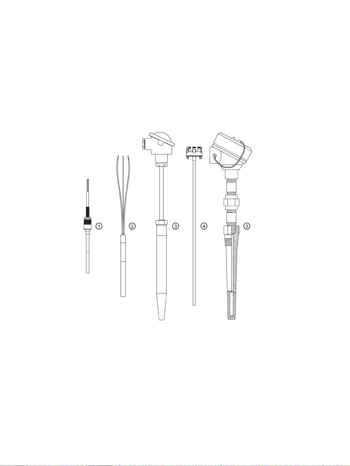
SITRANS TS product family
①
general use, compact design with connecting cable
②
general use, compact design
③
general use, modular design with connection head (European portfolio/ Chinese portfolio)
④
SITRANS TSinsert measuring insert for use in the SITRANS TS500 series
⑤
general use, modular design with connection head (North American portfolio/ Chinese portfolio)
SITRANS TS100 7MC71..
SITRANS TS200 7MC72..
SITRANS TS500 7MC75../7MC55..
SITRANS TS500 7MC65../7MC55..
TS100/TS200/TS300/TS500/TSinsert/TSthermowell
Compact Operating Instructions, 01/2018, A5E03920348-AE
17
Page 18

Description
Elementary sensors
3.2
Application
3.3
Functional principles
3.4
Nameplate structure
Positioning of nameplate
Note
SITRANS TS100/TS200 nameplate
Before commissioning, make sure the nameplate is securely fas
sensor in a visible location.
Device
Positioning of the nameplate
outer periphery of the ANSI adapter.
SITRANS TS100 7MC71..
On the sensor cable
3.2 Application
Resistance thermometers or thermocouples can be used for temperature measurement.
The temperature sensors of the SITRANS TS product family are used for measuring
temperatures in industrial plants.
Depending on the specifications, sensors can be combined with different connection heads,
extension tubes, and process connections. This makes the sensors suitable for a variety of
process engineering applications, in the following sectors:
● Petrochemical industry
● Pharmaceuticals industry
● Biotechnology
● Food production
Two different measuring principles are used for measuring temperatures.
● With resistance thermometers, the temperature is measured as a change in resistance.
Resistance thermometers, also called Resistance Temperature Devices (RTD), contain
sensor elements, like the Pt100 sensor elements in accordance with IEC 60751.
● With thermocouples, the temperature is the change in voltage (Seebeck effect). The
thermocouples are in accordance with IEC 584/DIN EN 60584.
tened to the temperature
SITRANS TSinsert 7MC701. On the bottom of the connecting plate or at the
TS100/TS200/TS300/TS500/TSinsert/TSthermowell
18 Compact Operating Instructions, 01/2018, A5E03920348-AE
Page 19
Description
Device
Positioning of the nameplate
SITRANS TS200 7MC72..
On the connector or on the sensor
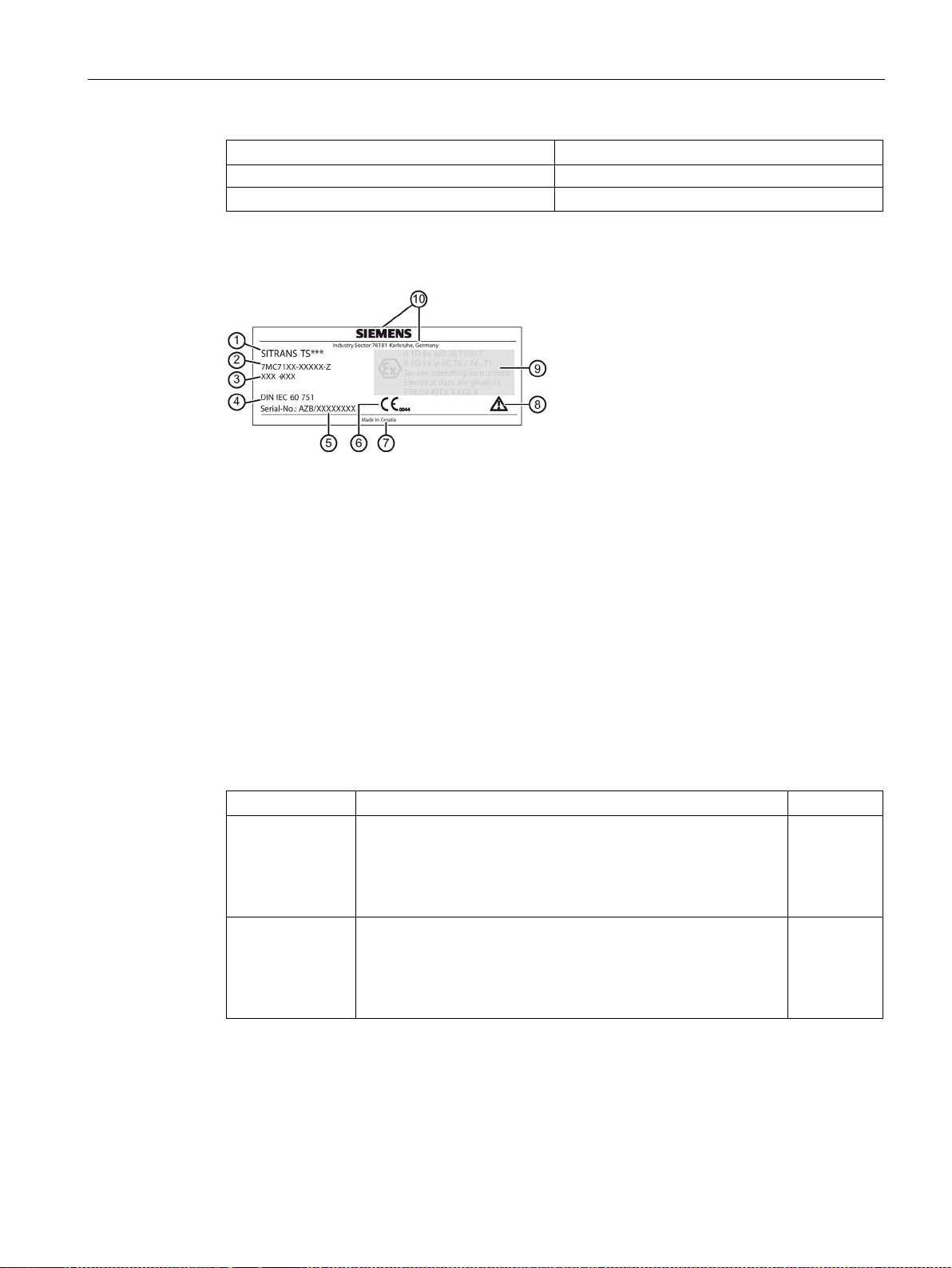
Example of nameplate
①
②
code)
③
Additional information on the type
④
Valid standard for the device
⑤
Serial number
⑥
CE marking
⑦
Place of manufacture
⑧
Consult the operating instructions.
⑨
tection/electrical data
⑩
3.5
Temperature transmitter for SITRANS TS500
Transmitter
Features
Sensor
3.5 Temperature transmitter for SITRANS TS500
SITRANS TS500 7MC.5.. On the connection head
Product name
Order number (machine-readable product
Type-specific information Explosion pro-
Manufacturer´s specifications
The following head-mounted transmitters can be combined with the temperature sensors
SITRANS TS500:
1)
TH100
TH200
• Base device
• Output 4 ... 20 mA
• Can be configured using simple software
: 12.5 mW
• P
o
• Universal device
• Output 4 ... 20 mA
• Can be configured using simple software
: 37 mW
• P
o
only
1)
or 2)
TS100/TS200/TS300/TS500/TSinsert/TSthermowell
Compact Operating Instructions, 01/2018, A5E03920348-AE
19
Page 20

Description
Transmitter
Features
Sensor
1)
Resistance thermometers
2)
Thermocouple
Note
SITRANS TS500 IEC Ex
If the contained SITRANS TH transmitter is not IEC Ex compliant, the TS500 nameplate has
ATEX marking only.
3.6
Measuring inserts for SITRANS TS500
3.6 Measuring inserts for SITRANS TS500
TH300
TH400
• Universal
• Output 4 ... 20 mA / HART
• Diagnostic functions
: 37 mW
• P
o
• Output: PROFIBUS PA or FOUNDATION Fieldbus
• Sensor redundancy
• Diagnostics
: 12 mW
• P
o
1)
or 2)
1)
or 2)
Measuring inserts for SITRANS TS500 temperature sensors are available in three variants:
● Variant 1:
DIN mounting disk for accommodating a transmitter or ceramic socket.
● Variant 2:
Fixed connection of the ends of the mineral insulated cable with a DIN ceramic socket.
● Variant 3:
Measuring insert in a spring-loaded adapter (ANSI).
TS100/TS200/TS300/TS500/TSinsert/TSthermowell
20 Compact Operating Instructions, 01/2018, A5E03920348-AE
Page 21
Description
3.7
Connection heads for SITRANS TS500
3.7 Connection heads for SITRANS TS500
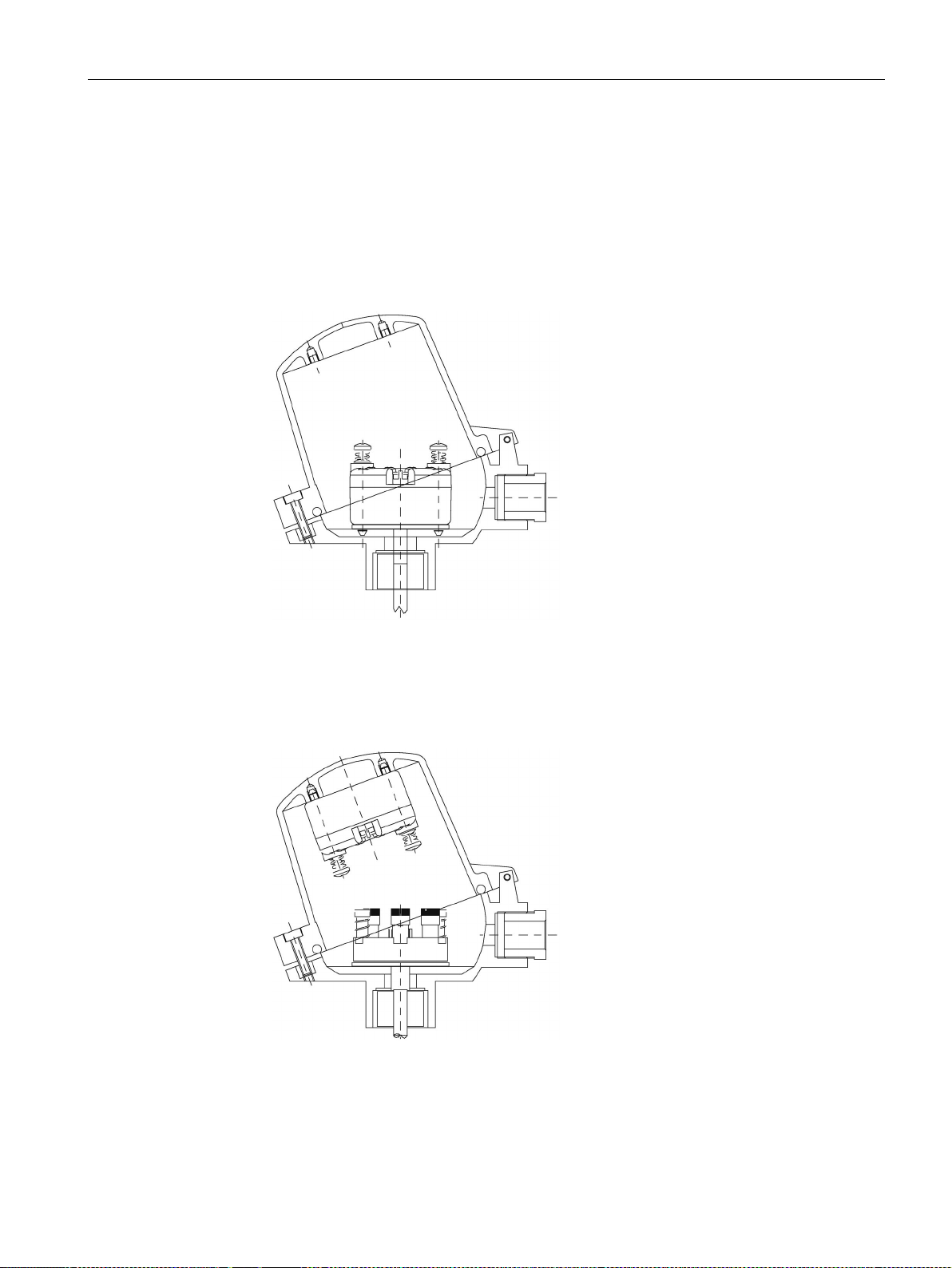
The transmitters can be mounted in connection heads of type B and bigger. The following
mounting types are possible:
● Measuring insert mounting
– Standard type with compact design
– Measuring insert (sensor) and transmitter form one unit
Figure 3-1 Measuring insert mounting of transmitter
● Hinged cover mounting
– Standard type for connection heads of type BC0: B head with high hinged cover
– Separate maintenance of the measuring insert and the transmitter is possible.
Figure 3-2 Hinged cover mounting of transmitter
TS100/TS200/TS300/TS500/TSinsert/TSthermowell
Compact Operating Instructions, 01/2018, A5E03920348-AE
21
Page 22

Description
3.7 Connection heads for SITRANS TS500
TS100/TS200/TS300/TS500/TSinsert/TSthermowell
22 Compact Operating Instructions, 01/2018, A5E03920348-AE
Page 23
4
4.1
Basic safety notes
WARNING
Exceeded maximum permissible operating pressure
WARNING
Unsuitable connecting parts
See also
CAUTION
Gasket between extension and protective tube
WARNING
Incorrect mounting at Zone 0
Risk of injury or poisoning.
The maximum permissible operating pressure depends on the device version, pressure
limit and temperature rating. The device can be damaged if the operating pressure is
exceeded. Hot, toxic and corrosive process media could be released.
Ensure that maximum permissible operating pressure of the device is not exceeded. Refer
to the information on the nameplate and/or in Technical data (Page 45).
Risk of injury or poisoning.
In case of improper mounting, hot, toxic, and corrosive process media could be released at
the connections.
• Ensure that connecting parts (such as flange gaskets and bolts) are suitable for
connection and process media.
Technical data (Page 45)
• Use gasket between device extension and protective tube only once.
Risk of explosion in hazardous areas.
• Ensure sufficient tightness at the process connection.
TS100/TS200/TS300/TS500/TSinsert/TSthermowell
Compact Operating Instructions, 01/2018, A5E03920348-AE
• Observe the standard IEC/EN 60079-14.
23
Page 24
Installing
CAUTION
Hot surfaces resulting from hot process media
CAUTION
External stresses and loads
4.1.1
Installation and location requirements
CAUTION
High vibration area
CAUTION
Direct sunlight
4.1 Basic safety notes
Risk of burns resulting from surface temperatures above 65 °C (149 °F).
• Take appropriate protective measures, for example contact protection.
• Make sure that protective measures do not cause the maximum permissible ambient
temperature to be exceeded. Refer to the information in Technical data (Page 45).
Damage to device by severe external stresses and loads (e.g. thermal expansion or pipe
tension). Process media can be released.
• Prevent severe external stresses and loads from acting on the device.
Especially with the stainless steel housing version of TS500, use short extensions or
external supports when used in a high vibration area.
When TS100/200 sensors are installed in a high vibrating area, use also external supports
to fix the probe stem: the unsupported length must not exceed 150 mm and the free end
must not exceed 100 mm.
Device damage.
The device can overheat or materials become brittle due to UV exposure.
• Protect the device from direct sunlight.
• Make sure that the maximum permissible ambient temperature is not exceeded. Refer
to the information in Technical data (Page 45).
TS100/TS200/TS300/TS500/TSinsert/TSthermowell
24 Compact Operating Instructions, 01/2018, A5E03920348-AE
Page 25

Installing
CAUTION
Process load
4.1.2
Proper mounting
DANGER
Protective tube ruptures
WARNING
Electrostatic charge
Note
Penetration of water into the plastic head type BM0
Device failure.
•
4.1 Basic safety notes
The thermowell is affected by the static, dynamic and chemical load from the process
parameters, e.g. static and dynamic load, flow induced vortexes. This has influence to the
shape of the thermometer, stem diameter and insertion length.
Ensure that the applicable and relevant directives and standards are respected, e.g. ASME
PTC 19.3, DIN43772 Annex 1-2, AD-directive, VDI/VDE 3511-5.
In critical applications, a thermowell stress calculation according ASME PTC 19.3-TW2016
or Dittrich/Klotter-method is recommended as an engineering service.
Protective tubes that are not suitable for the process or application in question can rupture
and result in serious damage to property and personal injuries.
• Make sure that the protective tube is suitable for the respective mounting method and
application. If necessary, check the selection and order data of your protective tube.
Danger of explosion in hazardous areas if electrostatic charges develop, for example, in
strong airflows in close proximity to belt conveyors.
• Avoid electrostatic charge at the plastic head type BM0 when defining the installation
site.
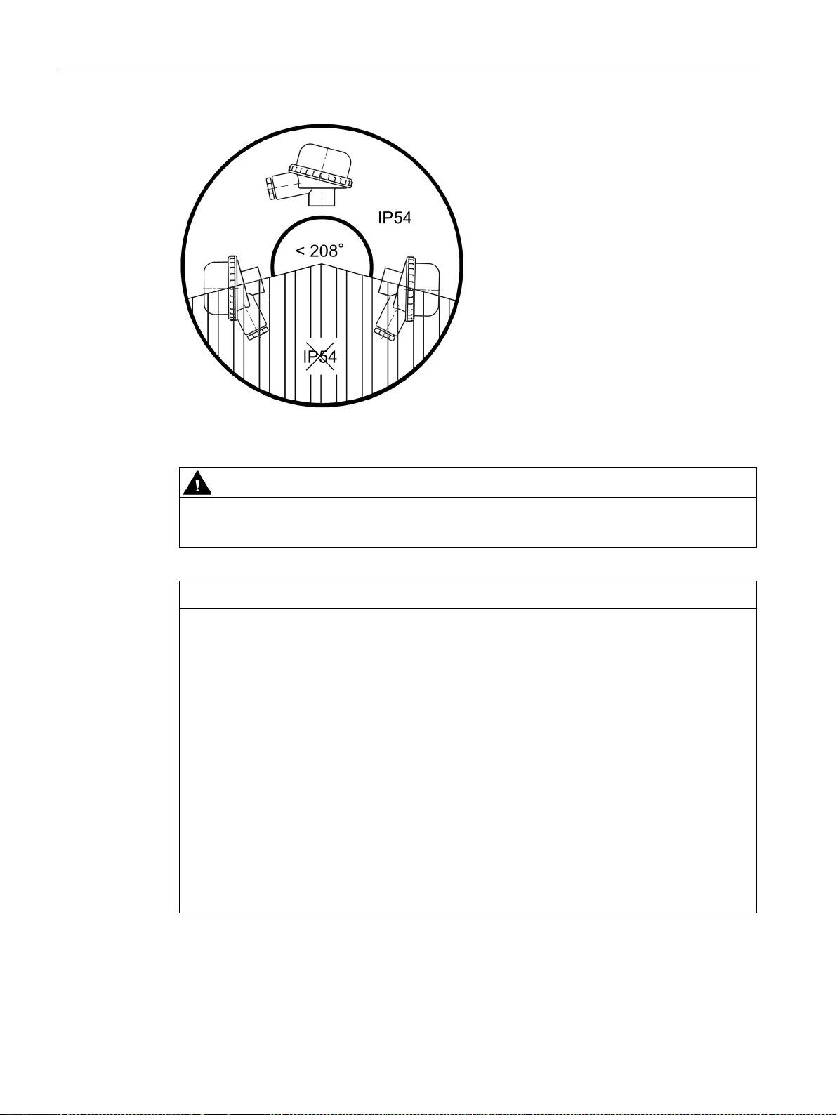
To reach IP54 with a plastic head type BM0, make sure that the mounting angle is in the
range of -14 to 194° (208°, see image below).
TS100/TS200/TS300/TS500/TSinsert/TSthermowell
Compact Operating Instructions, 01/2018, A5E03920348-AE
25
Page 26
Installing
CAUTION
Loss of IP protection
NOTICE
Incorrect mounting
4.1 Basic safety notes
Figure 4-1 Mounting angle of plastic head type BM0
Do not unscrew the device housing from the mounted parts with NPT threaded connection.
The device can be damaged, destroyed, or its functionality impaired through improper
mounting.
• Before installing, ensure there is no visible damage to the device.
• Make sure that process connectors are clean, and suitable gaskets and glands are
used.
• Mount the device using suitable tools. Refer to the information in Technical data
(Page 45) for installation torque requirements.
• Avoid temperature or mechanical shocks during mounting.
• Avoid excessive force or damaging of the on-site mechanical connections.
• Do not deform or adapt the thermowells.
• The use of additive seal or sealant (not in scope of delivery) is recommended between
sensor and thermowell.
• Thermowells from carbon steel are protected against corrosion. Clean the thermowell
before mounting to avoid poisoning of the sensor and mounting problems.
TS100/TS200/TS300/TS500/TSinsert/TSthermowell
26 Compact Operating Instructions, 01/2018, A5E03920348-AE
Page 27

Installing
Note
Loss of degree of protection
Damage to device if the enclosure is open or not properly closed. The degree of protection
specified on the nameplate is no longer guaranteed.
4.2
Install
Condition
Procedure
4.2 Install
Prior to mounting, make sure that the device is appropriately applied for the process
connection, media compatibility, temperature resistance and measuring range. See chapter
Technical data (Page 45).
1. Prevent faults caused by heat dissipation in non-representative placings by observing the
following rules:
2. Select an optimal immersion depth. Estimate the immersion depth using the formulas in
Table 8-16 Estimation of immersion depth (Page 57).
If the flow rate allows, sensor placing between 1/3 and 1/2 of the pipe diameter is
recommended.
3. If the process load on the thermowell allows the exposition, select a measurement
location with a high flow rate.
4. Ensure sufficient thermal insulation of the external components of the thermometer.
5. Ensure that external parts have as small surfaces as possible.
6. Select the optimum mounting position for the process in question.
TS100/TS200/TS300/TS500/TSinsert/TSthermowell
Compact Operating Instructions, 01/2018, A5E03920348-AE
27
Page 28
Installing
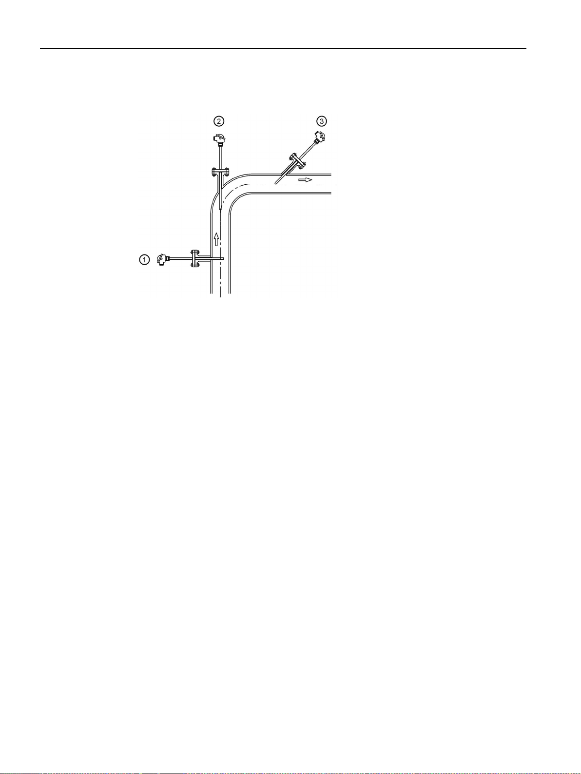
①
At a right angle to the flow
②
In a bend upstream
③
In an angle upstream
See also
4.2 Install
7. With small pipe diameters, mount the sensors upstream at an angle ③ or upstream in a
②.
bend
Figure 4-2 Possible mounting positions of the sensor
8. Use required torque values between device extension and protective tube as in Table 814 Torque values between device extension and protective tube (Page 56).
– If customer adjustments are necessary (M24 connections only), use required torque
values between device head and extension as in Table 8-15 Torque values between
device head and extension (Page 56).
– For SITRANS TS500 barstock version (only European portfolio 7MC752..) without
flange (type 4), use required torque values to complete the mounting of the device
extension to the protective tube as in Table 8-14 Torque values between device
extension and protective tube (Page 56).
Construction (Page 56)
TS100/TS200/TS300/TS500/TSinsert/TSthermowell
28 Compact Operating Instructions, 01/2018, A5E03920348-AE
Page 29

Installing
4.3
Install SITRANS TS300 Clamp-on
Note
Measurement position
Install on circular pipes only. Avoid installation next to angled pipes, near slide valves,
valves, pum
4.3 Install SITRANS TS300 Clamp-on
ps, etc.
1. Define the measurement position.
2. Apply heat sink compound to the metallic part of the temperature sensor.
3. For standard version: halved pipe collar allows for quick and easy mounting on the pipe
using two mounting screws.
For bracket version: mount on pipe using one mounting screw.
– If the pipe is not fully occupied by medium during installation, mount the temperature
sensor on the underside of the pipe.
4. Firmly tighten the mounting screws (4 Nm torque).
5. Mount the vibration protection and hand-tighten.
– You can remove the measuring insert only after you have released the RTD recessed
grip screw(s).
– Do not twist the housing.
– Use RTD recessed grip screw for installation, only.
– Do not apply force to the transmitter housing (e. g. during opening/closing of lid).
– Because the locking plugs are fitted with internal gaskets, they are only suited for
ambient temperatures to 100 °C (212 °F).
TS100/TS200/TS300/TS500/TSinsert/TSthermowell
Compact Operating Instructions, 01/2018, A5E03920348-AE
29
Page 30

Installing
4.4
Disassembly
WARNING
Incorrect disassembly
4.4 Disassembly
The following risks may result from incorrect disassembly:
- Injury through electric shock
- Risk through emerging media when connected to the process
- Risk of explosion in hazardous area
In order to disassemble correctly, observe the following:
• Before starting work, make sure that you have switched off all physical variables such
as pressure, temperature, electricity etc. or that they have a harmless value.
• If the device contains hazardous media, it must be emptied prior to disassembly. Make
sure that no environmentally hazardous media are released.
• Secure the remaining connections so that no damage can result if the process is started
unintentionally.
TS100/TS200/TS300/TS500/TSinsert/TSthermowell
30 Compact Operating Instructions, 01/2018, A5E03920348-AE
Page 31

5
5.1
Basic safety notes
WARNING
Unsuitable cables, cable glands and/or plugs
See also
WARNING
Incorrect selection of type of protection
WARNING
Improper power supply
Risk of explosion in hazardous areas.
• Use only cable glands/plugs that comply with the requirements for the relevant type of
protection.
• Tighten the cable glands in accordance with the torques specified in Construction
(Page 56).
• Close unused cable inlets for the electrical connections.
• When replacing cable, glands use only cable glands of the same type.
• After installation, check that the cables are seated firmly.
Technical data (Page 45)
Risk of explosion in areas subject to explosion hazard.
This device is approved for several types of protection.
1. Decide in favor of one type of protection.
2. Connect the device in accordance with the selected type of protection.
3. In order to avoid incorrect use at a later point, make the types of protection that are not
used permanently unrecognizable on the nameplate.
Risk of explosion in hazardous areas as result of incorrect power supply, e.g. using direct
current instead of alternating current.
• Connect the device in accordance with the specified power supply and signal circuits.
The relevant specifications can be found in the certificates, in Electrical data (Page 57)
or on the nameplate.
TS100/TS200/TS300/TS500/TSinsert/TSthermowell
Compact Operating Instructions, 01/2018, A5E03920348-AE
31
Page 32
Connecting
WARNING
Lack of equipotential bonding
Exception
WARNING
Unprotected cable ends
WARNING
Loss of degree of protection
WARNING
Lemo plug in hazardous areas
WARNING
Improper laying of shielded cables
5.1 Basic safety notes
Risk of explosion through compensating currents or ignition currents through lack of
equipotential bonding.
• Ensure that the device is potentially equalized.
: It may be permissible to omit connection of the equipotential bonding for devices
with type of protection "Intrinsic safety Ex i".
Risk of explosion through unprotected cable ends in hazardous areas.
• Protect unused cable ends in accordance with IEC/EN 60079-14.
When connecting the SITRANS TS100 or TS200 with type protection "Intrinsically safe",
ensure the following:
• Adhere to the requirements for electrical connection seperation.
• Use IP54 rated enclosure.
For Lemo plug version (7MC7xxx-xxxx2-xxx) make sure the cable ends are in an
environment free from dust, water, or shock.
Risk of explosion through compensating currents between hazardous area and the
non-hazardous area.
• Shielded cables that cross into hazardous areas should be grounded only at one end.
• If grounding is required at both ends, use an equipotential bonding conductor.
TS100/TS200/TS300/TS500/TSinsert/TSthermowell
32 Compact Operating Instructions, 01/2018, A5E03920348-AE
Page 33

Connecting
WARNING
Connecting device in energized state
Exceptions
Note
Electromagnetic compatibility (EMC)
You can use this device in industrial environments, households and small businesses.
For metal housings there is an increased electromagnetic compatibility compared to high
frequency radiation. This protection can be increased by grounding the housing, see
Electrical connection
Note
Improvement of interference immunity
•
•
•
•
•
5.1 Basic safety notes
Risk of explosion in hazardous areas.
• Connect devices in hazardous areas only in a de-energized state.
:
• Devices having the type of protection "Intrinsic safety Ex i" may also be connected in
energized state in hazardous areas.
• Exceptions for type of protection "Non-sparking nA" (Zone 2) are regulated in the
relevant certificate.
-
(Page 35).
Lay signal cables separate from cables with voltages > 60 V.
Use cables with twisted wires.
Keep device and cables at a distance from strong electromagnetic fields.
Take account of the conditions for communication specified in the Technical data
(Page 45).
Use shielded cables to guarantee the full specification according to HART/PA/FF.
TS100/TS200/TS300/TS500/TSinsert/TSthermowell
Compact Operating Instructions, 01/2018, A5E03920348-AE
33
Page 34

Connecting
5.1.1
For SITRANS TSinsert
WARNING
Flying leads
greater than 500 V.
5.1.2
For SITRANS TSinsert/TS100/TS200/TS500
NOTICE
Ambient temperature too high
5.1.3
For SITRANS TS100/TS200
WARNING
Use of plug connectors in explosive dust atmosphere
5.1 Basic safety notes
Risk of explosion in hazardous areas due to loss of Intrinsic Safety protection.
• Shorten the ends of flying leads to the appropriate length.
• Keep a minimal clearance of 2 mm between the wires of different circuits, or any circuit
and the grounded enclosure.
- or Use heat shrinking tubes TFE-R 1/8": wall thickness ≥ 0.2 mm, di-electrical strength
Damage to cable sheath.
• At an ambient temperature ≥ 60 °C (140 °F), use heat-resistant cables suitable for an
ambient temperature at least 20 °C (36 °F) higher.
Danger of explosion.
Temperature sensors of the SITRANS TS100 and SITRANS TS200 series must not be
used together with plug connectors in atmospheres with combustible dust.
• Do not use plug connectors in areas with combustible dust.
TS100/TS200/TS300/TS500/TSinsert/TSthermowell
34 Compact Operating Instructions, 01/2018, A5E03920348-AE
Page 35

Connecting
5.1.4
For SITRANS TS500
NOTICE
Condensation in the device
5.2
Electrical connection
Condition
Procedure
See also
5.2 Electrical connection
Damage to device through formation of condensation if the temperature difference between
transportation or storage and the mounting location exceeds 20 °C (36 °F).
• Before taking the device into operation let the device adapt for several hours in the new
environment.
● Temperature transmitter is installed.
1. Release the fixing screws on the enclosure cover and remove the enclosure cover.
2. Insert the connecting cable through the cable gland.
3. Connect the wires to the relevant connecting terminals. Observe the terminal assignment.
– Electrical connection of resistance thermometers (Page 36)
– Electrical connection of thermocouples (Page 37)
– Electrical connection of connectors (Page 37)
Electrical data (Page 57)
TS100/TS200/TS300/TS500/TSinsert/TSthermowell
Compact Operating Instructions, 01/2018, A5E03920348-AE
35
Page 36
Connecting
5.3
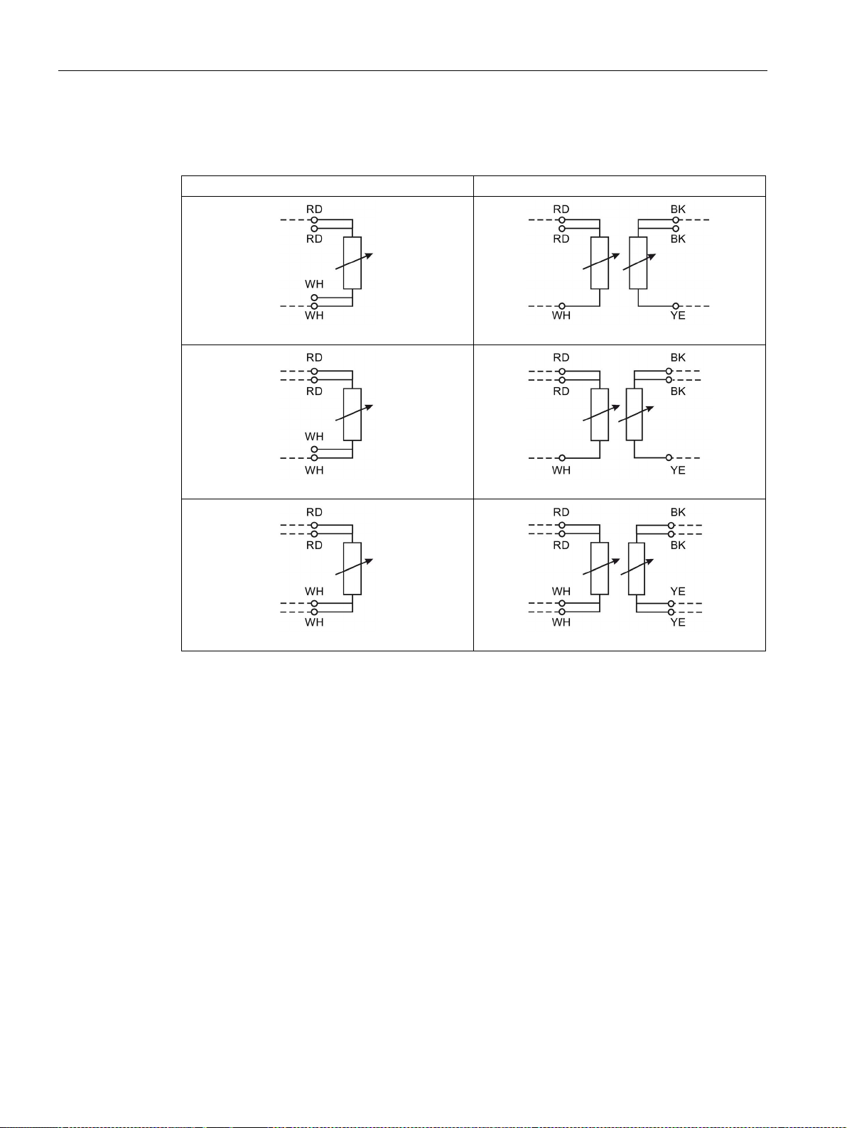
Electrical connection of resistance thermometers
1 x RTD
2 x RTD
2-wire connection
2-wire connection
3-wire connection
3-wire connection
4-wire connection
4-wire connection
5.3 Electrical connection of resistance thermometers
Abbreviation of color: RD = red; WH = white; YE = yellow; BK = black
TS100/TS200/TS300/TS500/TSinsert/TSthermowell
36 Compact Operating Instructions, 01/2018, A5E03920348-AE
Page 37
Connecting
5.4
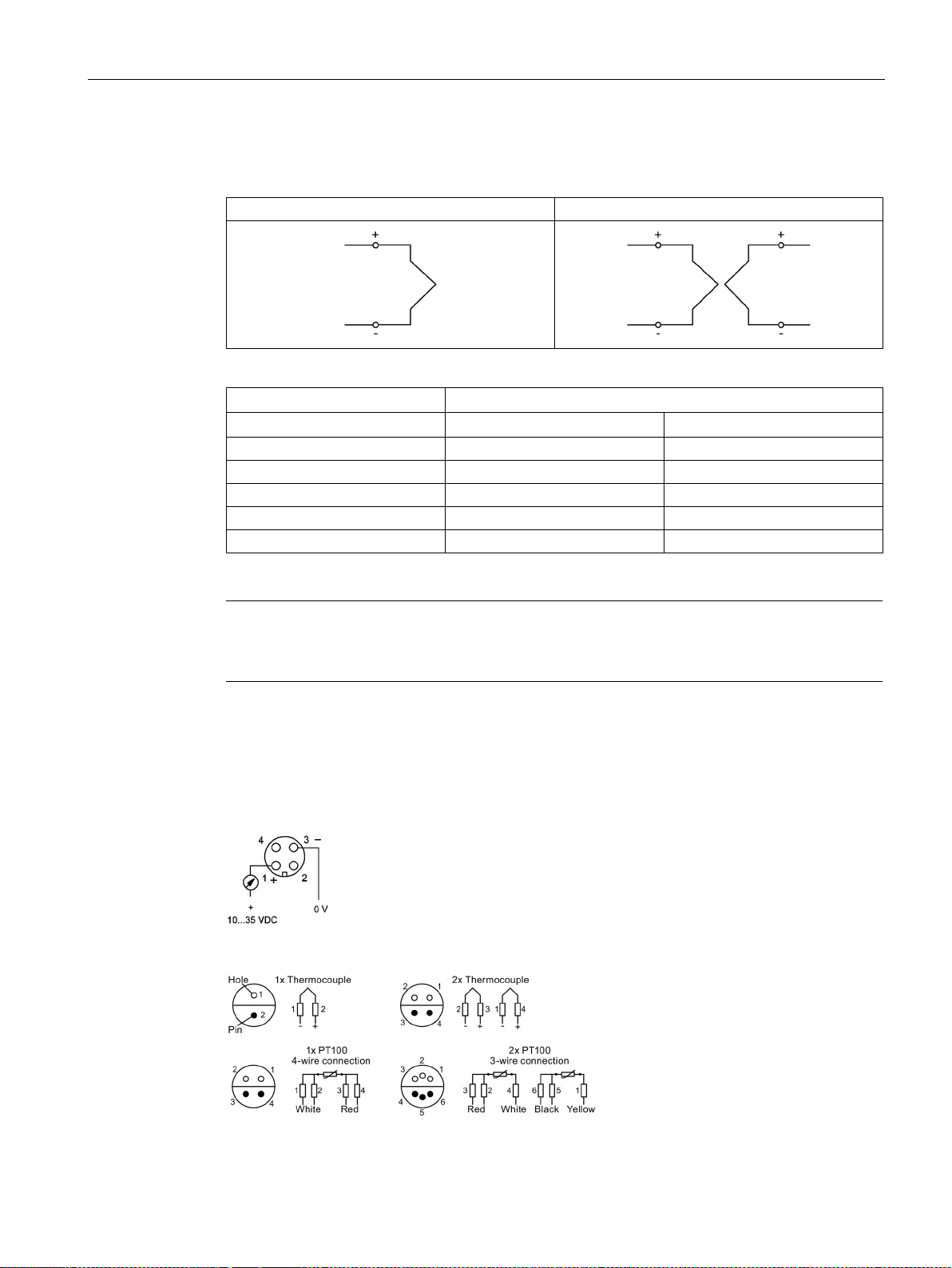
Electrical connection of thermocouples
1 thermocouple
2 thermocouples
Thermocouples
Cable colors
Type + -
J
Black
White
K
Green
White
N
Pink
White
E
Violet
White
T
Brown
White
Note
2 thermocouples
On the terminal block is an additional mark to differentiate between sensor 1 and sensor 2.
5.5
Electrical connection of connectors
5.4 Electrical connection of thermocouples
M12 x 1 connection with SITRANS TH100 transmitter
Lemo 1S coupling for SITRANS TS100/TS200
TS100/TS200/TS300/TS500/TSinsert/TSthermowell
Compact Operating Instructions, 01/2018, A5E03920348-AE
37
Page 38
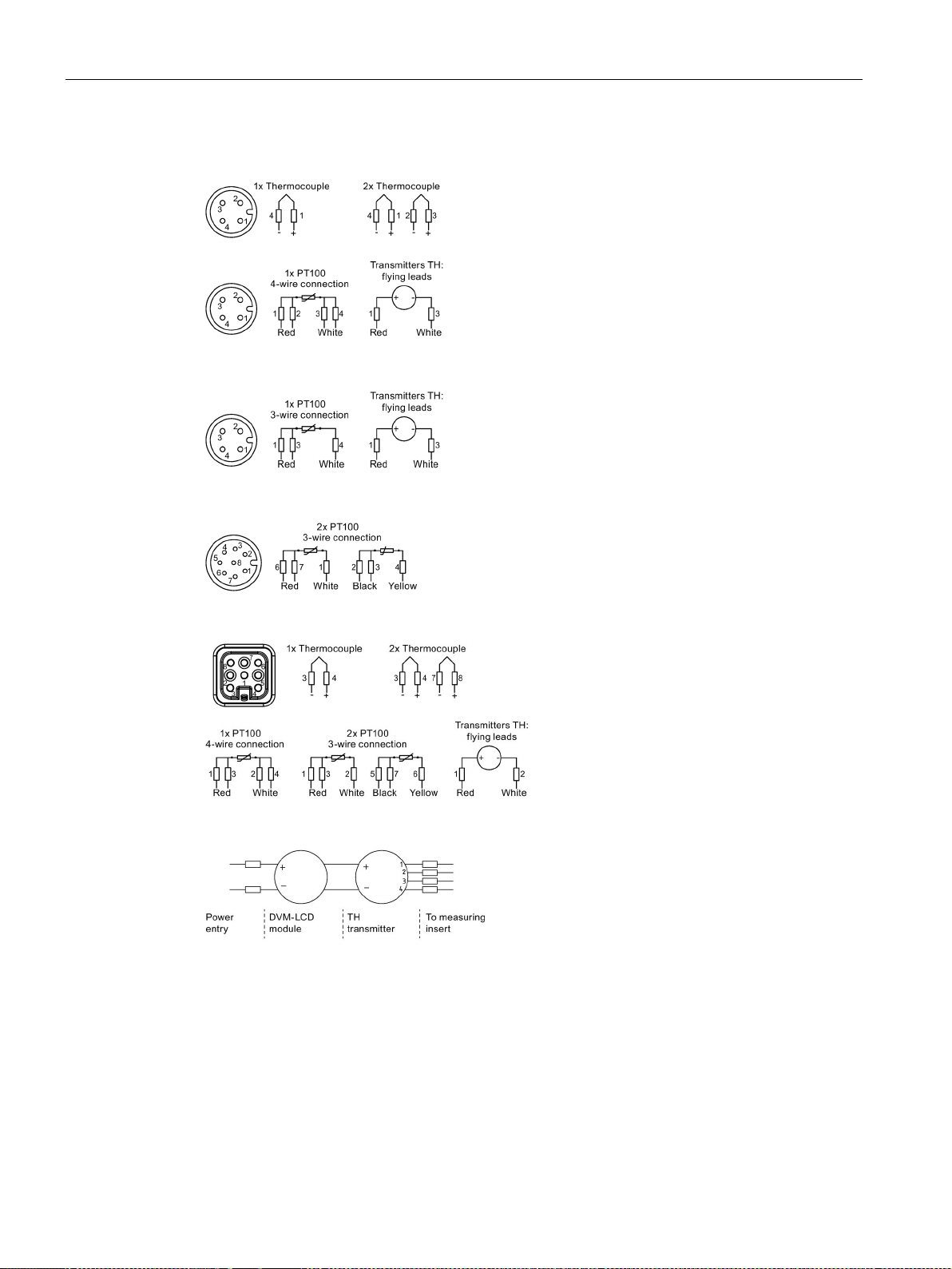
Connecting
5.5 Electrical connection of connectors
M12 connector for single sensors for SITRANS TS100/TS200/TS500
M12 connector for single sensors SITRANS TS300
M12 connector for double sensors SITRANS TS100
HAN7 D connector for SITRANS TS500
LCD and transmitter connection
TS100/TS200/TS300/TS500/TSinsert/TSthermowell
38 Compact Operating Instructions, 01/2018, A5E03920348-AE
Page 39
6
6.1
Basic safety notes
WARNING
Improper commissioning in hazardous areas
WARNING
Hot surfaces
WARNING
Loss of explosion protection
WARNING
Opening device in energized state
Exception
Device failure or risk of explosion in hazardous areas.
• Do not commission the device until it has been mounted completely and connected in
accordance with the information in Technical data (Page 45).
• Before commissioning take the effect on other devices in the system into account.
Risk of burns resulting from hot surfaces.
• Take corresponding protective measures, for example by wearing protective gloves.
Danger of explosion in hazardous areas if the device is open or not properly closed.
Risk of explosion in hazardous areas
• Only open the device in a de-energized state.
• Check prior to commissioning that the cover, cover locks, and cable inlets are
assembled in accordance with the directives.
: Devices having the type of protection "Intrinsic safety Ex i" may also be opened
in energized state in hazardous areas.
TS100/TS200/TS300/TS500/TSinsert/TSthermowell
Compact Operating Instructions, 01/2018, A5E03920348-AE
39
Page 40

Commissioning
Note
Loss of degree of protection
Damage to device if the enclosure is open or not properly closed. The degree of protection
specified on the nameplate is no longer guaranteed.
6.2
Commissioning
Requirements
Procedure
6.2 Commissioning
Verify that the following commissioning conditions are satisfied:
● You have connected the sensors correctly. For further details, see:
– Electrical connection of resistance thermometers (Page 36)
– Electrical connection of thermocouples (Page 37)
● Verify that the electrical connections are firmly tightened to the suitable torque.
● The following applies in particular with device versions with explosion protection:
– Verify whether the cable glands are appropriate for the process and are correctly
tightened.
– The electrical data must match the specified Ex-relevant values.
● All seals must be present, placed correctly and undamaged.
1. Close the connection head. Fully screw on the cover for device versions with flameproof
enclosures.
2. Connect the sensor integrated in the process to the power supply.
TS100/TS200/TS300/TS500/TSinsert/TSthermowell
40 Compact Operating Instructions, 01/2018, A5E03920348-AE
Page 41

7
WARNING
Impermissible repair of explosion protected devices
WARNING
Humid environment
Recalibration
Note
Recalibration intervals
Define the recalibration intervals for the specific process or plant. With constant operating
temperatures and a low load, the reference values are as fo
•
•
Risk of explosion in hazardous areas
• Repair must be carried out by Siemens authorized personnel only.
Risk of electric shock.
• Avoid working on the device when it is energized.
• If working on an energized device is necessary, ensure that the environment is dry.
• Make sure when carrying out cleaning and maintenance work that no moisture
penetrates the inside of the device.
Temperature sensors are essentially maintenance-free. However, we recommend
recalibration under the following conditions:
● Processes with strong vibrations or changes in temperature.
● Food, pharma, biotechnology applications (annually), TS300 only.
● Processes that demand high measuring accuracy and safety.
llows:
< 2 years at temperatures up to 400 °C
< 5 years at temperatures up to 200 °C
TS100/TS200/TS300/TS500/TSinsert/TSthermowell
Compact Operating Instructions, 01/2018, A5E03920348-AE
41
Page 42

Service and maintenance
Recalibration of SITRANS TS300
Description
Recalibration procedure
measurement.
perform calibration.
from the pipe collar.
shape of the RTD unit only.
depth = 8 mm (0.31").
(176 °F) when using a temperature transmitter].
internal reference sensor only.
turer when heating the calibrator.
inserting it in the calibrator sleeve.
indicated by the nameplate.
the RTD temperature and adjust if necessary.
1
Take into account any line resistance.
unit.
Clamp-on version Do not disconnect the pipe sleeve from the pipe - leave
the measuring position unchanged for reproducible
It is not necessary to disconnect the power supply to
Loosen recessed grip screw(s) to remove the RTD connector or housing and unscrew the measuring insert
Block calibrators Use calibrator sleeves that have been adapted to the
Insert must have a borehole of ∅6.00 mm (0.24") H7,
Do not exceed 100 °C (212 °F) at locking plug [80 °C
Use block calibrator with dual-zone-technology with
Ohmic measurement
Observe the adjustment time specified by the manufac-
1 Apply heat sink compound to the RTD unit before
2 Check the electrical connector (cable end) as
3 After inserting the RTD unit, wait about 5 minutes
for the temperature to settle.
4 Compare the temperature of the calibrator with
2 Apply heat sink compound to the RTD plug-in
TS100/TS200/TS300/TS500/TSinsert/TSthermowell
42 Compact Operating Instructions, 01/2018, A5E03920348-AE
Page 43

Service and maintenance
7.1
Cleaning
Cleaning the enclosure
WARNING
Electrostatic charge
7.2
Return procedure
Required forms
7.1 Cleaning
● Clean the outside of the enclosure with the inscriptions and the display window using a
cloth moistened with water or a mild detergent.
● Do not use any aggressive cleansing agents or solvents, e.g. acetone. Plastic parts or the
painted surface could be damaged. The inscriptions could become unreadable.
Risk of explosion in hazardous areas if electrostatic charges develop, for example, when
cleaning plastic surfaces with a dry cloth.
• Prevent electrostatic charging in hazardous areas.
Enclose the bill of lading, return document and decontamination certificate in a clear plastic
pouch and attach it firmly to the outside of the packaging.
● Delivery note
● Return goods delivery note
(http://www.siemens.com/processinstrumentation/returngoodsnote)
with the following information:
– Product (item description)
– Number of returned devices/replacement parts
– Reason for returning the item(s)
● Decontamination declaration (http://www.siemens.com/sc/declarationofdecontamination)
With this declaration you warrant "that the device/replacement part has been carefully
cleaned and is free of residues. The device/replacement part does not pose a hazard for
humans and the environment."
If the returned device/replacement part has come into contact with poisonous, corrosive,
flammable or water-contaminating substances, you must thoroughly clean and
decontaminate the device/replacement part before returning it in order to ensure that all
hollow areas are free from hazardous substances. Check the item after it has been
cleaned.
TS100/TS200/TS300/TS500/TSinsert/TSthermowell
Compact Operating Instructions, 01/2018, A5E03920348-AE
Any devices/replacement parts returned without a decontamination declaration will be
cleaned at your expense before further processing.
43
Page 44

Service and maintenance
7.3
Disposal
Devices d
disposed of in the municipal waste disposal services according to the
Directive 2012/19/EC on waste electronic and electrical equipment
(WEEE).
Devices can be returned to the suppli
proved disposal service for eco
regulations valid in your country.
Further information about devices containing batteries can be found at:
Information about battery / product retu
(https://support.industry.siemens.com/cs/document/109479891/)
7.3 Disposal
escribed in this manual should be recycled. They may not be
er within the EC, or to a locally ap-
-friendly recycling. Observe the specific
rn (WEEE)
TS100/TS200/TS300/TS500/TSinsert/TSthermowell
44 Compact Operating Instructions, 01/2018, A5E03920348-AE
Page 45

8
8.1
Rated conditions
Storage
Storage temperature
-40 ... +80 °C (-40 ... +176 °F)
SITRANS TSinsert/SITRANS TS100/TS200/TS500
SITRANS TS300
-20 °C
SITRANS TSinsert/SITRANS TS100/TS200/TS500
-40 °C
AU0 (option G and U) in Non-SIL-applications
Caution
Ambient temperature of electronic and cable glands assembled to SITRANS TS500
accordingly. Check the operating instructions of your used electronic and cable gland for more
information.
Note
not rated to -50 °C but -40 °C.
See also
8.1.1
Maximum permissible ambient temperatures in the connection area of the sensor
8.1.1.1
General limitations for compression fittings
Degree of protection in accordance with EN 60529 See nameplate.
Degree of protection is archived, when the device is correctly installed. See chapter Installing (Page 23).
SITRANS TS500 type 7MC75.. with head type AG0 and
If electronic and cable glands are assembled, their minimum permitted ambient temperature must also be rated up to the
minimum ambient temperature shown in the table above, otherwise the minimum ambient temperature of the complete
SITRANS TS500 is derated
Siemens temperature transmitters SITRANS TH as well as HAN 7D and M12 (option codes G12 and G13) connectors are
-50 °C
Nameplate structure (Page 18)
Due to the PTFE sealing, standard compression fittings are limited to a maximum
temperature of 200 °C.
TS100/TS200/TS300/TS500/TSinsert/TSthermowell
Compact Operating Instructions, 01/2018, A5E03920348-AE
45
Page 46

Technical data
8.1.1.2
SITRANS TS100
Note
Application SITRANS TS100
SITRANS
he temperature classes T4 and
T6. Pay attention to the temperature resistance of the connection cables. See
temperature too high
8.1 Rated conditions
TS100 temperature sensors are only approved for t
Ambient
(Page 34).
TS100/TS200/TS300/TS500/TSinsert/TSthermowell
46 Compact Operating Instructions, 01/2018, A5E03920348-AE
Page 47

Technical data
8.1.1.3
SITRANS TS500
Gas
Dust
SITRANS TS500
in "Intrinsic safety Ex i"
- or in "Non-sparking nA"
in flameproof enclosure (Ex d)
is part of a "Intrinsic safety Ex i"
- or in non-intrinsically safe circuits
(Ex tb)
relevant temperature class in the
Table 8-6 Type 2N (Page 52).
Notice!
Table 8-10 Type 2N (Page 54).
8.1 Rated conditions
Without electronic
(only enclosure
with terminal base)
With temperature
transmitters
SITRANS TH or
third party transmitters
Refer to your TS500 head and
Table 8-3 Gas Ex i/nA
(Page 50),
Table 8-4 Gas Ex i/nA
(Page 51),
Table 8-5 Type 2N (Page 51)
and
T
= (T1 - ∆T2G) ≤ T2
a_max
= see relevant certificate of
T
1
the temperature transmitters.
∆T2G and T
Table 8-3 Gas Ex i/nA
(Page 50),
Table 8-4 Gas Ex i/nA
(Page 51),
Table 8-5 Type 2N (Page 51)
and
Table 8-6 Type 2N (Page 52).
= see
2
Refer to your TS500 head
without electronic in the
Table 8-7 Gas Ex d (Page 52)
and
Table 8-8 Type 2N (Page 53).
Refer to your TS500 head with
electronic in
Table 8-7 Gas Ex d (Page 52)
and
Table 8-8 Type 2N (Page 53).
When installing third party
transmitter, keep in mind the
max. permitted power consumption of 3 W.
Refer to your TS500 head
without electronic in the
Table 8-9 Dust Ex i/tb (Page 53)
and
Table 8-10 Type 2N (Page 54).
Refer to your TS500 head with
electronic" in
Table 8-9 Dust Ex i/tb (Page 53)
and
Table 8-10 Type 2N (Page 54).
When installing third party
transmitter, keep in mind the
max. permitted power consumption of 1 W. Assumed max.
surface temperature of the
TS500 enclosure is 85 °C.
If the max. permissible ambient
temperature of third party
transmitters is lower then 85 °C
calculate as follow:
= T1 - ∆T1D - ∆T2D
T
a_max
T1 = see relevant certificate of
the temperature transmitters.
∆T1D = 22K (max. permitted
power consumption of 1 W)
∆T2D = See Table 8-9 Dust
Ex i/tb (Page 53) and
TS100/TS200/TS300/TS500/TSinsert/TSthermowell
Compact Operating Instructions, 01/2018, A5E03920348-AE
47
Page 48

Technical data
Gas
Dust
SITRANS TS500
in "Intrinsic safety Ex i"
- or in "Non-sparking nA"
in flameproof enclosure (Ex d)
is part of a "Intrinsic safety Ex i"
- or in non-intrinsically safe circuits
(Ex tb)
T
T
T3 = Max. permissible ambient temperature SITRANS TH100/200/300 and display DVM-LCD
See also
8.1 Rated conditions
With temperature
transmitters
SITRANS
TH100/200/300
and Display DVMLCD
(A5E33119275
respectively
7MF4997-1BS)
T
= T3 ≤ T2
a_max
= see
T
3
Table 8-1 Gas hazardous area
Zone 1 / 21 / Div. 1 (Page 49).
T2 = see
Table 8-3 Gas Ex i/nA
(Page 50),
Table 8-4 Gas Ex i/nA
(Page 51),
Refer to your TS500 head with
electronic in the
Table 8-7 Gas Ex d (Page 52)
and
Table 8-8 Type 2N (Page 53).
T
T
ous area Zone 21 / Div. 1
(Page 49).
Table 8-5 Type 2N (Page 51)
and
Table 8-6 Type 2N (Page 52).
= Max. permissible ambient temperature of temperature transmitter according certificate
1
= Max. permissible ambient temperature for the respective connection head without transmitter
2
SITRANS TH100/200/300 and display DVM-LCD (Page 49)
Certificates (Page 107)
Gas hazardous area: Ex i / IS / Ex nA/ec / NI (Page 50)
= T3
a_max
= see Table 8-2 Dust hazard-
3
Gas hazardous area: Ex d / XP (Page 52)
TS100/TS200/TS300/TS500/TSinsert/TSthermowell
48 Compact Operating Instructions, 01/2018, A5E03920348-AE
Page 49

Technical data
SITRANS TH100/200/300 and display DVM-LCD
Gas hazardous area Zone 1 / 21 / Div. 1
Permitted electrical supply parameters
T3 = Permissible ambient temperature
Assembly of DVM-LCD
A5E33119275 (HW: 05)
Assembly of DVM-LCD
7MF4997-1BS (HW: 03)
Pi = 750 mW
Pi = 610 mW
Pi = 530 mW
Dust hazardous area Zone 21 / Div. 1
Permitted electrical supply parameters
T3 = Permissible ambient temperature
Assembly of DVM-LCD
A5E33119275 (HW: 05)
Assembly of DVM-LCD
7MF4997-1BS (HW: 03)
Pi = 750 mW
Pi = 610 mW
Pi = 530 mW
See also
8.1 Rated conditions
You can find the values of ∆T2G in the tables
Table 8-3 Gas Ex i/nA (Page 50),
Table 8-4 Gas Ex i/nA (Page 51),
Table 8-5 Type 2N (Page 51) and
Table 8-6 Type 2N (Page 52) and
∆T2D in the table Table 8-9 Dust Ex i/tb (Page 53) and
Table 8-10 Type 2N (Page 54).
Table 8- 1
Ui = 30 V
= 100 mA
I
i
Ui = 27 V
Ii = 90 mA
Ui = 25,2 V
= 84 mA
I
i
Table 8- 2
Ui = 30 V
= 100 mA
I
i
T4: -40 °C ≤ T3 ≤ +75 °C - ∆T2G
T6: -40 °C ≤ T
T4: -40 °C ≤ T3 ≤ +85 °C - ∆T2G
T6: -40 °C ≤ T3 ≤ +50 °C - ∆T2G
T4: -40 °C ≤ T3 ≤ +85 °C - ∆T2G
T6: -40 °C ≤ T
T85 °C: -40 °C ≤ T3 ≤ +53°C - ∆T2D T85 °C: -40 °C ≤ T3 ≤ +45°C - ∆T2D
≤ +45 °C - ∆T2G
3
≤ +52 °C - ∆T2G
3
T4: -40 °C ≤ T
≤ +67 °C - ∆T2G
3
T4: -40 °C ≤ T3 ≤ 80 °C - ∆T2G
T4: -40 °C ≤ T
≤ +85 °C - ∆T2G
3
Ui = 27 V
Ii = 90 mA
Ui = 25,2 V
Ii = 84 mA
Gas hazardous area: Ex i / IS / Ex nA/ec / NI (Page 50)
Dust hazardous area: Ex i / IS / Ex tb / DIP (Page 53)
TS100/TS200/TS300/TS500/TSinsert/TSthermowell
Compact Operating Instructions, 01/2018, A5E03920348-AE
T85 °C: -40 °C ≤ T3 ≤ +63 °C - ∆T2D T85 °C: -40 °C ≤ T3 ≤ +60 °C - ∆T2D
T85 °C: -40 °C ≤ T3 ≤ +63 °C - ∆T2D T85 °C: -40 °C ≤ T3 ≤ +63 °C - ∆T2D
49
Page 50

Technical data
Gas hazardous area: Ex i / IS / Ex nA/ec / NI
without
transmitter
Head type
AU0
AV0, SITRANS TF
BA0: BB0; BC0;
BD0; AA0, AB0,
AC0, KJ0, BS0,
AG0
T
max
head
120 °C
85 °C
100 °C
Temperature class
T4
T6
T4
T6
T4
T6
Medium
temperature
(°C)
Temperature increase by
medium
ΔT2G (K)
Extension
length "X"
(mm)
T2 in °C
T2 in °C
T2 in °C
T2 in °C
T2 in °C
T2 in °C
440 °C
12
80
108
68
73
68
88
68
6
150
114
74
79
74
94
74
3
300
117
77
82
77
97
77
290 °C
22
40
98
58
63
58
78
58
11
80
109
69
74
69
89
69
5
150
115
75
80
75
95
75
2
300
118
78
83
78
98
78
200 °C
16
40
104
64
69
64
84
64
8
80
112
72
77
72
92
72
4
150
116
76
81
76
96
76
2
300
118
78
83
78
98
78
130 °C
9
40
111
71
76
71
91
71
5
80
115
75
80
75
95
75
3
150
117
77
82
77
97
77
1
300
119
79
84
79
99
79
80 °C
5
40
120
80
85
80
100
80
3
80
120
80
85
80
100
80
1
150
120
80
85
80
100
80
0
300
120
80
85
80
100
80
8.1 Rated conditions
The maximum ambient temperatures T2 for the respective connection head
given by the medium is already considered there.
Table 8- 3 Gas Ex i/nA
23 40 97 57 62 57 77 57
can be obtained from the cells in the following tables. The temperature increase
TS100/TS200/TS300/TS500/TSinsert/TSthermowell
50 Compact Operating Instructions, 01/2018, A5E03920348-AE
Page 51

Technical data
Head type
BT0, AH0
BMO
BP0
T
max
head
80 °C
80 °C
100 °C
Temperature class
T6
T6
T4
T6
Medium temperature (°C)
Temperature increase by
medium
ΔT2G (K)
Extension
length "X" (mm)
T2 in °C
T2 in °C
T2 in °C
T2 in °C
440 °C
12
23*
80
68
57
77
57
6
11*
150
74
69
89
69
3
300
77
77
97
77
290 °C
22
40
58
58
78
58
11
80
69
69
89
69
2
300
78
78
98
78
200 °C
16
40
64
64
84
64
8
80
72
72
92
72
4
150
76
76
96
76
2
300
78
78
98
78
130 °C
9
40
71
71
91
71
5
80
75
75
95
75
3
150
77
77
97
77
1
300
79
79
99
79
80 °C
5
40
80
80
100
80
3
80
80
80
100
80
1
150
80
80
100
80
0
300
80
80
100
80
* Value for head type BP0 and BMO
Head type
AU0
AV0, SITRANS TF
T
max
head
120 °C
85 °C
Temperature class
T4
T6
T4
T6
Medium temperature (°C)
Temperature
increase by medium ΔT2G (K)
T2 in °C
T2 in °C
T2 in °C
T2 in °C
100 °C
7
120
73
78
73
80 °C
8.1 Rated conditions
Table 8- 4 Gas Ex i/nA
23 43* 40 57 37 57 37
5 150 75 75 95 75
Table 8- 5 Type 2N
5 120 80 85 80
TS100/TS200/TS300/TS500/TSinsert/TSthermowell
Compact Operating Instructions, 01/2018, A5E03920348-AE
51
Page 52

Technical data
Head type
BA0: BB0; BC0; BD0; AA0, AB0,
AC0, KJ0, BS0, AG0
BMO, BT0,
AH0
BP0
T
max
head
100 °C
80 °C
100 °C
Temperature class
T4
T6
T6
T4
T6
Medium temperature (°C)
Temperature
increase by
medium ΔT2G
(K)
T2 in °C
T2 in °C
T2 in °C
T2 in °C
T2 in °C
100 °C
100 73 73 100 73
80 °C 5 100
80
80
100
80
Gas hazardous area: Ex d / XP
with or without
transmitter
Head type
AH0, AV0,
SITRANS TF
AG0, UG0
AU0, UU0
T
max
head
85 °C
100 °C
120 °C
Temperature class
T6
T4
T3
T4
Max. permitted power consumption
of electronic (W)
0 ... 31)
With or without
electronic
0
Without elec-
tronic
1 ... 31)
With electronic
0
Without elec-
tronic
1 ... 31)
With electronic
Medium temperature (°C)
Extension
length "X"
(mm)
T
a_max
in °C
T
a_max
in °C
T
a_max
in °C
T
a_max
in °C
T
a_max
in °C
440 °C
40 43
76
53
96
48
80
55
88
65
108
60
150 ... 300
61
94
71
114
66
290 °C
40
54
87
64
107
59
80 ... 300
61
94
71
114
66
200 °C
40
58
91
68
111
63
80 ... 300
63
96
73
116
68
130 °C
40 ... 300
61
94
71
114
66
80 °C
40 ... 300
67
100
77
120
72
1)
electronic are incorporated.
8.1 Rated conditions
Table 8- 6 Type 2N
7
The maximum ambient temperatures Ta for the respective connection head
given by the medium is already considered there.
Table 8- 7 Gas Ex d
can be obtained from the cells in the following tables. The temperature increase
For the determination of ambient temperatures, maximum enclosure temperature of 85 °C was taken as a basis when
TS100/TS200/TS300/TS500/TSinsert/TSthermowell
52 Compact Operating Instructions, 01/2018, A5E03920348-AE
Page 53

Technical data
Head type
AH0, AV0,
SITRANS TF
AG0, UG0
AU0, UU0
T
max
head
85 °C
100 °C
120 °C
Temperature class
T6
T4
T3
T4
Max. permitted power
consumption of elec-
tronic (W)
0 ... 31)
With or without
electronic
0
Without electronic
1 ... 31)
With electronic
0
Without electronic
1 ... 31)
With electronic
Medium temperature (°C)
T
a_max
in °C
T
a_max
in °C
T
a_max
in °C
T
a_max
in °C
T
a_max
in °C
100 °C 60
100
70
120
65
80 °C
1)
electronic are incorporated.
Dust hazardous area: Ex i / IS / Ex tb / DIP
with or without
transmitter
Head type
AH0, AV0, SITRANS TF
AG0, UG0
AU0, UU0
T
max
head
85 °C
100 °C
120 °C
Max. permitted power consumption of
electronic (W)
0
Without
electronic
11)
With elec-
tronic
0
Without
electronic
11)
With elec-
tronic
0
Without
electronic
11)
With elec-
tronic
Medium
temperature (°C)
Temper-
ature
increase
by Medi-
um ΔT2D
(K)
Extension
length "X"
(mm)
T
a_max
in °C
T
a_max
in °C
T
a_max
in °C
T
a_max
in °C
T
a_max
in °C
T
a_max
in °C
440 °C
36
40 49
--
64
--
84
--
18
80
67
45
82
45
102
45
8
150
77
55
92
55
112
55
4
300
81
59
96
59
116
59
250 °C
22
40
63
--
78
--
98
--
11
80
74
52
89
52
109
52
5
150
80
58
95
58
115
58
1
300
84
62
99
62
119
62
8.1 Rated conditions
Table 8- 8 Type 2N
67 100 77 120 72
For the determination of ambient temperatures, maximum enclosure temperature of 85 °C was taken as a basis when
The maximum ambient temperatures Ta for the respective connection head
given by the medium is already considered there.
Table 8- 9 Dust Ex i/tb
can be obtained from the cells in the following tables. The temperature increase
TS100/TS200/TS300/TS500/TSinsert/TSthermowell
Compact Operating Instructions, 01/2018, A5E03920348-AE
53
Page 54

Technical data
Head type
AH0, AV0, SITRANS TF
AG0, UG0
AU0, UU0
T
max
head
85 °C
100 °C
120 °C
Max. permitted power consumption of
electronic (W)
0
Without
electronic
11)
With elec-
tronic
0
Without
electronic
11)
With elec-
tronic
0
Without
electronic
11)
With elec-
tronic
Medium
temperature (°C)
Temper-
ature
increase
by Medi-
um ΔT2D
(K)
Extension
length "X"
(mm)
T
a_max
in °C
T
a_max
in °C
T
a_max
in °C
T
a_max
in °C
T
a_max
in °C
T
a_max
in °C
120 °C
5
80
80
58
95
58
120
58 3 150
82
60
97
60
120
60
0
300
85
63
100
63
120
63
1)
Assembled temperature transmitter e.g. SITRANS TH without Display DVM-LCD
Head type
AH0, AV0, SITRANS TF
AG0, UG0
AU0, UU0
T
max
head
T85 °C
100 °C
120 °C
Max. permitted power con-
sumption of electronic (W)
0
Without elec-
tronic
11)
With elec-
tronic
0
Without elec-
tronic
11)
With elec-
tronic
0
Without elec-
tronic
11)
With elec-
tronic
Medium
temperature
(°C)
Temperature increase by
Medium
ΔT2D (K)
T
a_max
in °C
T
a_max
in °C
T
a_max
in °C
T
a_max
in °C
T
a_max
in °C
T
a_max
in °C
100 °C
80 °C
8
85
63
100
63
120
63
1)
Assembled temperature transmitter for example SITRANS TH
8.1.2
Maximum permitted sample temperatures within the process
Note
Permissible ambient temperature at sensor
The maximum permissible ambient temperature at the sensor simultaneously corresponds to
the highest permissible sample temperature.
The minimum permissible sample temperatures are up to
of the temperature sensor.
8.1 Rated conditions
10 40 75 53 90 53 120 53
Table 8- 10 Type 2N
10 75 53 100 53 120 53
-200 °C depending on the version
TS100/TS200/TS300/TS500/TSinsert/TSthermowell
54 Compact Operating Instructions, 01/2018, A5E03920348-AE
Page 55

Technical data
See also
Resistance thermometers
1 x RTD TF/3 mm/6 mm
2 x RTD TF/3 mm/6 mm
1 x RTD WW/3 mm/6 mm
2 x RTD WW/3 mm/6 mm
Max. permissible sample temperature (°C)
Certified transmitter in Zone 0 with type of
protection "Intrinsically safe"
Certified transmitter in Zone 1, 2 with type
of protection "Intrinsically safe"
P0: 0 … ≤37 mW 1)
P0: ≥37 … ≤100 mW
P0: 0 … ≤37 mW 1)
P0: ≥37 … ≤100
mW
T1 = 450 °C -10K
348
340
436
428
T2 = 300 °C -10K
228
220
286
278
T3 = 200 °C - 5K
152
144
191
183
T6 = 85 °C - 5K
60
52
76
68
1)
For example SITRANS TH
Thermocouples
1 x TC type J, K, N /3 mm
2 x TC type J, K, N /3 mm
1 x TC type J, K, N /6 mm
2 x TC type J, K, N /6 mm
Max. permissible sample temperature (°C)
Certified transmitter in Zone 0 with type of
protection "Intrinsically safe"
Certified transmitter in Zone 1, 2 with type
of protection "Intrinsically safe"
P0: 0 … 100 mW
T1 = 450 °C -10K
351
439
T2 = 300 °C -10K
231
289
T3 = 200 °C -5K
155
194
T4 = 135 °C -5K
103
129
T6 = 85 °C -5K
63
79
8.1 Rated conditions
Maximum permitted sample temperatures within the process (Page 54)
Table 8- 11 RTD temperature sensor (Rth max=120 K/W)
T4 = 135 °C - 5K 100 92 126 118
Table 8- 12 Thermocouple temperature sensor (Rth max=15 K/W)
TS100/TS200/TS300/TS500/TSinsert/TSthermowell
Compact Operating Instructions, 01/2018, A5E03920348-AE
55
Page 56

Technical data
8.1.3
Measuring range
Note
Measuring ranges
The application or possible operating temperatures depend on the configurat
temperature sensor.
8.2
Construction
Torques for M20 accessories
Plastic head
Metal head
Cable diameter
Plastic cable gland
5.0 Nm
5.0 Nm
6 ... 12 mm
Metal cable gland
N/A
5.0 Nm
5 ... 14 mm
Adapter M20 to NPT½
5.0 Nm
5.0 Nm
N/A
Connection type
Torque value
M14 thread
25 Nm
M18 thread
40 Nm
G½ thread; M20 threads
50 Nm
wrench
Head type
Torque value
Metal head
20 Nm
Plastic heads
5 Nm
8.2 Construction
The measuring range refers to the temperature limits in which the thermometer can be used
practically for measuring purposes. Depending on the loads at the place of use and the
required accuracies, the actual measuring range may decrease.
ion of the
Table 8- 13 Torque values for M20 accessories
SITRANS TS500 with head types A requires a minimum thickness of the wrench flat of
5 mm. The maximal wrench size is SW24.
Table 8- 14 Torque values between device extension and protective tube
½ inch NPT Hand-tight and one to two complete turns with a
Table 8- 15 Torque values between device head and extension
TS100/TS200/TS300/TS500/TSinsert/TSthermowell
56 Compact Operating Instructions, 01/2018, A5E03920348-AE
Page 57

Technical data
Medium
Immersion depth (calculation)1)
Water
Immersion depth ≥ TSL1) + (5 x ∅
protective tube
)
1)
TSL = Temperature Sensitive Length
8.3
Electrical data
Devices for general use
Measured current
I
Measuring
(Pt 1000)
0.1 ... 0.3 mA
Devices in explosion-protected version
Equipment protection by means of intrinsic safety
Li = 15 µH/m
Equipment protection by means of non incendive
peak values
U
max
= 32 V 1)
1)
Maximum safety voltage
Equipment protection by means of Explosionproofed / Dust-Ignition proofed
P = 25/37/50/100 mW
Effective internal capacitance and internal inductance
DVM-LCD
SITRANS TH100
∑
Ci
16 nF
13 nF
29 nF
Li
3 µH
106 µH
109 µH
8.3 Electrical data
Table 8- 16 Estimation of immersion depth
Air Immersion depth ≥ TSL1) + (10 to 15 x ∅
I
(Pt 100) 0.3 ... 1.0 mA
Measuring
For connecting to circuits with the following
peak values
protective tube
Ui ≤ 30 V
≤ 100 mA
I
i
P
= Po (transmitter)
i
= 700 pF/m
C
i
)
For connecting to circuits with the following
For connecting to circuits with the following
peak values
Un = 30 V
U
= 45 V
max
(U
= 35 V for USA/Canada)
max
TS100/TS200/TS300/TS500/TSinsert/TSthermowell
Compact Operating Instructions, 01/2018, A5E03920348-AE
57
Page 58

Technical data
8.4
Measuring tolerances for resistance thermometers
Tolerance classes
Tolerance class
Precision
∆t
±1.8x0.30 °F +0.0050x|t[°F]-32|
±1.8x0.15 °F +0.0020x|t[°F]-32|
±1.8x0.10 °F +0.0017x|t[°F]-32|
Tolerances
Action
Tolerance
Precision
Range
Class B
Basic accuracy
-50 ... +400 °C (-58 ... +752 °F)
Class A
Increased accuracy
-30 ... +300 °C (-22 ... +572 °F)
Class AA (1/3 B)
High accuracy
0 ... +150 °C (+32 ... +302 °F)
Class B
Basic accuracy
-50 ... +400 °C (-58 ... +752 °F)
Class A
Increased accuracy
-30 ... +300 °C (-22 ... +572 °F)
Class AA (1/3 B)
High accuracy
0 ... +150 °C (+32 ... +302 °F)
Class B
Basic accuracy
-196 ... +600 °C (-320 ... +1112 °F)
Class A
Increased accuracy
-100 ... +450 °C (-148 ... +842 °F)
Class AA (1/3 B)
Increased accuracy
-50 ... +250 °C (-58 ... +482 °F)
8.4 Measuring tolerances for resistance thermometers
The tolerance classes of the resistance thermometers are defined as follows in accordance
with IEC 60751:
Class B Basic accuracy ±(0.30 °C +0.0050|t[°C]|)
Class A Increased accuracy ±(0.15 °C +0.0020|t[°C]|)
Class AA (1/3 B) High accuracy ±(0.10 °C +0.0017|t[°C]|)
The following tables provide an overview of the validity ranges of these tolerances. When
you use a thermometer above the specified limits, the values of the next lower accuracy
class apply.
Basic version
With increased vibra-
tion resistance
With extended measur-
ing range
If an RTD will be subjected in a higher temperature as specified in the class, the sensor will
be declassified to the referring accuracy class. For enduring operation near 400 °C we
recommend the use of an extended measuring range RTD, instead of basic and increased
vibration versions.
TS100/TS200/TS300/TS500/TSinsert/TSthermowell
58 Compact Operating Instructions, 01/2018, A5E03920348-AE
Page 59

Technical data
8.5
Measuring accuracy for thermocouples
Tolerance classes
Catalog versions
Type
Basic accuracy, Class 2
Increased accuracy, Class 1
(631 °F ... 2012 °F ±0.0075x|t[°F]-32|)
(707 °F ... 1832 °F ±0.004x|t[°F]-32|)
(631 °F ... 1832 °F ±0.0075x|t[°F]-32|)
(707 °F ... 1832 °F ±0.004x|t[°F]-32|)
(631 °F ... 1382 °F ±0.0075x|t[°F]-32|)
(707 °F ... 1382 °F ±0.004x|t[°F]-32|)
Further base thermocouples
Type
Basic accuracy, Class 2
Increased accuracy, Class 1
(271 °F ... 662 °F ±0.0075x|t[°F]-32|)
(257 °F ... 662 °F ±0.004x|t[°F]-32|)
(631 °F ... 1652 °F ±0.0075x|t[°F]-32|)
(707 °F ... 1472 °F ±0.004x|t[°F]-32|)
Further noble thermocouples
Type
Basic accuracy, Class 2
Increased accuracy, Class 1
(1112 °F ... 2912 °F ±0.0025x|t[°F]-32|)
(2012 °F ... 2912 °F ±1,8+0,003x(t[°F]-2012)
8.5 Measuring accuracy for thermocouples
The tolerance classes of the thermocouples are defined in the following table in accordance
with IEC 584/DIN EN 60584:
N -40 °C ... +333 °C ±2.5 °C
(-40 °F ... +631 °F ±4.5 °F)
333 °C ... 1100 °C ±0.0075x|t[°C]|
K -40 °C ... +333 °C ±2.5°C
(-40 °F... +631 °F ±4.5 °F)
333 °C ... 1000 °C ±0.0075x|t[°C]|
J -40 °C ... +333 °C ±2.5 °C
(-40 °F ... +631 °F ±4.5 °F)
333 °C ... 750 °C ±0.0075x|t[°C]|
T -40 °C ... +133 °C ±1 °C
(-40 °F ... +271 °F ±1.8 °F)
133 °C ... 350 °C ±0.0075x|t[°C]|
E -40 °C ... +333 °C ±2.5°C
(-40 °F... +631 °F ±4.5 °F)
333 °C ... 900 °C ±0.0075x|t[°C]|
-40 °C ... +375 °C ±1.5 °C
(-40 °F ... +707 °F ±2.7 °F)
375 °C ... 1000 °C ±0.004x|t[°C]|
-40 °C ... +375 °C ±1.5 °C
(-40 °F... +707 °F ±2.7 °F)
375 °C ... 1000 °C ±0.004x|t[°C]|
-40 °C ... +375 °C ±1.5 °C
(-40 °F ... +707 °F ±2.7 °F)
375 °C ... 750 °C ±0.004x|t[°C]|
-40 °C ... +125 °C ±0.5 °C
(-40 °F ... +257 °F ±0.9 °F)
125 °C ... 350 °C ±0.004x|t[°C]|
-40 °C ... +375 °C ±1.5 °C
(-40 °F... +707 °F ±2.7 °F)
375 °C ... 800 °C ±0.004x|t[°C]|
R,S 0 °C ... 600 °C ±1.5 °C
(32 °F ... +1112 °F ±2.7 °F)
600 °C ... 1600 °C ±0.0025x|t[°C]|
B 600 °C ... 1700 °C ±0.0025x|t[°C]|
(1112 °F ... 3092 °F ±0.0025x|t[°F]-32|)
TS100/TS200/TS300/TS500/TSinsert/TSthermowell
Compact Operating Instructions, 01/2018, A5E03920348-AE
0 °C ... 1100 °C ±1 °C
(32 °F ... +2012 °F ±1.8 °F)
1100 °C ... 1600 °C ±[1 + 0.003 x(t -1100)] °C
-
59
Page 60

Technical data
8.6
Certificates and approvals
8.6.1
SITRANS TSInsert/TS100/TS200/TS500
SITRANS TSInsert/TS100/TS200/TS500
"Intrinsic safety" type of protection
PTB 09 ATEX 2014 X
IECEx PTB 11.0010 X
IEC 60079-26 Ed 3 2014
GB 12476.4-2010
8.6 Certificates and approvals
ATEX/IECEx
EN 60079-0:2012/A11:2013
EN 60079-11:2012
EN 60079-15:2010
EN 60079-7:2015
EN 60079-26:2015
IEC 60079-0 Ed 6 2011
IEC 60079-11 Ed 6 2011
IEC 60079-15 Ed 4 2010
IEC 60079-7 Ed 5 2015
NEPSI
GYJ14.1005X
GB 3836.1-2010
GB 3836.4-2010
GB 3836.20-2010
GB 3836.8-2003
IEC 61241-0:2004
II 1 D Ex ia IIIC T 200 °C Da
II 1 G Ex ia IIC T6 / T4 ... T1 Ga
II 3 G Ex ic IIC T6 / T4 ... T1 Gc
Ex iaD 20 T200
Ex ibD 21 T200
Ex ia IIC T1/T2/T3/T4/T6 Ga
Ex ib IIC T1/T2/T3/T4/T6 Gb
Ex ic IIC T1/T2/T3/T4/T6 Gc
TS100/TS200/TS300/TS500/TSinsert/TSthermowell
60 Compact Operating Instructions, 01/2018, A5E03920348-AE
Page 61

Technical data
SITRANS TSInsert/TS100/TS200/TS500
IEC 60079-26-2006
CAN/CSA-C22.2 No. 60529:2005
8.6 Certificates and approvals
EACEx
RU C-DE.AA87.B.00006
IEC 60079-0-2011
IEC 60079-1-2011
IEC 60079-11-2010
IEC 60079-15-2010
IEC 60079-31-2010
cCSAus
70037146
FM Class 3600:2011
FM Class 3611:2004
FM Class 3615:2006
FM Class 3616:2013
FM Class 3810:2005
ANSI/ISA 60079-0:2009
ANSI/ISA 60079-1:2013
ANSI/ISA 60079-31:2013
ANSI/NEMA 250:1991
ANSI/IEC 60529:2004
CSA C22.2 No. 0.4:2013
CSA C22.2 No. 0.5:2012
CSA C22.2 No. 14
CSA C22.2 No. 25:2014
CSA C22.2 No. 30:2005
CSA C22.2 No. 94
CSA C22.2 No. 142:1993
CSA C22.2 No. 157:2002
CSA C22.2 No. 213:1999
CAN/CSA-C22.2 No. 60079-0:2011
CAN/CSA-C22.2 No. 60079-1:2011
CAN/CSA-C22.2 No. 60079-31:2012
Ex ia IIIC T200 °C Da X
0Ex ia IIC T6/T4 …T1 Ga X
2Ex ic IIC T6/T4 … T1 Gc X
Class I, Division 1, Groups A, B, C, D T6/T4 … T1
Class I, Division 2, Groups A, B, C, D T6/T4 … T1
Class II Division 1 Groups E, F, G T6/T4 … T1
Class II Division 2 Groups F, G T6/T4 … T1
Class III
Ex ia IIC T6/T4 … T1 Ga
Ex ia IIIC T200 °C Da
AEx ia IIC T6/T4 … T1 Ga
AEx ia IIIC T200 °C Da
Ex ic IIC T6/T4 … T1 Gc
Class I, Zone 2, AEx ic IIC T6/T4 … T1 Gc
TS100/TS200/TS300/TS500/TSinsert/TSthermowell
Compact Operating Instructions, 01/2018, A5E03920348-AE
61
Page 62

Technical data
8.6.2
SITRANS TS500
SITRANS TS500
of protection
PTB 10 ATEX 1005 X
IECEx PTB 10.0018 X
IEC 60079-31 Ed. 2 2013
GB 12476.1-2000
8.6 Certificates and approvals
"Explosionproofed" and "dust-ignition proofed" type
ATEX/IECEx
EN 60079-0:2012/A11:2013
EN 60079-1:2014
EN 60079-26:2015
EN 60079-31:2014
IEC 60079-0 Ed. 6 2011
IEC 60079-1 Ed. 7 2014
IEC 60079-26 Ed. 3 2014
NEPSI
GYJ14.1004X
GB 3836.1-2010
GB 3836.2-2010
GB 3836.20-2010
EACEx
RU C-DE.AA87.B.00006
IEC 60079-0-2011
IEC 60079-1-2011
IEC 60079-11-2010
IEC 60079-15-2010
IEC 60079-31-2010
IEC 60079-26-2006
II 1/2 G Ex d IIC T6, T4, T3 Ga/Gb
II 1/2 D Ex tb IIIC T85 °C, 100 °C or 150 °C
Ex d IIC T3/T4/T6 Ga/Gb
DIP A20/21 TA85 °C/100 °C/150 °C IP65
Ga/Gb Ex d IIC, T6, T4, T3 X
Ex tb IIIC T85 °C,T100 °C,T150 °C Da/Db X
TS100/TS200/TS300/TS500/TSinsert/TSthermowell
62 Compact Operating Instructions, 01/2018, A5E03920348-AE
Page 63

Technical data
SITRANS TS500
CAN/CSA-C22.2 No. 61010-1
CAN/CSA-C22.2 No. 61010-1
8.6 Certificates and approvals
cCSAus
70037146
FM Class 3600:2011
FM Class 3611:2004
FM Class 3615:2006
FM Class 3616:2013
FM Class 3810:2005
ANSI/ISA 60079-0:2009
ANSI/ISA 60079-1:2013
ANSI/ISA 60079-31:2013
ANSI/NEMA 250:1991
ANSI/IEC 60529:2004
CSA C22.2 No. 0.4:2013
CSA C22.2 No. 0.5:2012
CSA C22.2 No. 14
CSA C22.2 No. 25:2014
CSA C22.2 No. 30:2005
CSA C22.2 No. 94
CSA C22.2 No. 142:1993
CSA C22.2 No. 157:2002
CSA C22.2 No. 213:1999
CAN/CSA-C22.2 No. 60079-0:2011
CAN/CSA-C22.2 No. 60079-1:2011
CAN/CSA-C22.2 No. 60079-31:2012
CAN/CSA-C22.2 No. 60529:2005
Class I, Division 1, Groups A, B, C, D T6, T4 … T1
Class I, Division 1, Groups B, C, D T6, T4 … T1 (type code
7MC65..-.....-.(G;U)..)
Class I, Division 2, Groups A, B, C, D T6, T4 … T1
Class II Division 1 Groups E, F, G T6, T4 … T1
Class II Division 2 Groups F, G T6, T4 … T1
Class III
Ex d IIC T6, T4,T3 Ga/Gb
Ex tb IIIC T85 °C, T100 °C, T150 °C Da/Db
AEx tb IIIC T85 °C, T100 °C, T150 °C Da/Db
cFMus
FM17US0010X (USA)
FM17CA0005X (Canada)
FM Class 3600:2011
FM Class 3611:2004
FM Class 3615:2006
FM Class 3616:2013
FM Class 3810:2005
ANSI/ISA 60079-0:2009
ANSI/ISA 60079-1:2013
ANSI/ISA 60079-31:2013
ANSI/NEMA 250:1991
ANSI/IEC 60529:2004
CSA C22.2 No. 0.4:2013
CSA C22.2 No. 0.5:2012
CSA C22.2 No. 14
CSA C22.2 No. 25:2014
CSA C22.2 No. 30:2005
CSA C22.2 No. 94
CSA C22.2 No. 142:1993
CSA C22.2 No. 157:2002
CSA C22.2 No. 213:1999
CAN/CSA-C22.2 No. 60079-0:2011
CAN/CSA-C22.2 No. 60079-1:2011
CAN/CSA-C22.2 No. 60079-31:2012
CAN/CSA-C22.2 No. 60529:2005
Class I Division 1, Groups A, B, C, D; T* Ta = -40 °C to +Tx°C
Class II, III, Division 1, Groups E, F, G; T* Ta = -40 °C to +Tx°C
Class I, II, III, Division 2, Group A, B, C, D, F, G; T* Ta = -40°C to
+Tx °C
Class I, Zone 1, AEx d IIC T* Gb Ta = -40 °C to +Tx °C (FMus only)
Class I, Zone 1, Ex d IIC T* Gb Ta = -40 °C to +Tx °C (cFM only)
Zone 21 AEx tb IIIC T* Db Ta = -40 °C to +Tx °C (FMus only)
Ex tb IIIC T* Db Ta = -40°C to +Tx °C (cFM only)
Type 4X, IP66/67
TS100/TS200/TS300/TS500/TSinsert/TSthermowell
Compact Operating Instructions, 01/2018, A5E03920348-AE
63
Page 64

Technical data
8.6 Certificates and approvals
TS100/TS200/TS300/TS500/TSinsert/TSthermowell
64 Compact Operating Instructions, 01/2018, A5E03920348-AE
Page 65

9
9.1
Overview
Versions
Description
Versions
Description
Versions
Description
or head
The following tables contain brief descriptions of the temperature sensors as well as
references to the corresponding dimensional drawings.
Table 9- 1 Overview of SITRANS TS100 dimensional drawings
Basic version
Mineral-insulated cable
Table 9- 2 Overview of SITRANS TS200 dimensional drawings
Basic sensor, flying leads, LEMO 1S
coupling, M12, thermocouple coupling,
mini connection head
Table 9- 3 Overview of SITRANS TS300 dimensional drawings
• Temperature sensors in cable design, for universal use, plastic-insulated
version, for unfavorable space conditions.
• SITRANS TS100 (Page 69)
• Temperature sensors in cable design, for universal use, mineral-insulated
version, for unfavorable space conditions.
• SITRANS TS100 (Page 69)
• Temperature sensors in cable design, for universal use, mineral-insulated
version, for unfavorable space conditions.
• SITRANS TS200 (Page 70)
Modular design with a wide range of
process connections for hygienic applications
Clamp-on design with collar, strap, or
hook mounting, integrated transmitter
TS100/TS200/TS300/TS500/TSinsert/TSthermowell
Compact Operating Instructions, 01/2018, A5E03920348-AE
• Temperature sensors for pipe and vessels in a hygienic application.
• Design according EHEDG
• SITRANS TS300 (Page 71)
• Clamp-on temperature sensor particulary for satured steam sterilization.
• SITRANS TS300 (Page 71)
65
Page 66

Dimension drawings
Versions
Description
Temperature sensors for vessels and pipelines, threaded process connection,
Temperature sensors for vessels and pipelines, threaded process connection,
9.1 Overview
Table 9- 4 Overview of SITRANS TS500 dimensional drawings
Type 2, pipe version without process
connection
Type 2N, pipe version with screw-in
nipple
Type 2G, pipe version with screw-in
nipple and extension
Type 2F, pipe version with flange and
extension
Type 3, fast pipe version without process connection
Type 3G, fast pipe version with screwin nipple and extension
Type 3F, fast pipe version with flange
and extension
Types 4 and 4F, full material version,
with extension
Type ST, threaded tapered well
(7MC65..)
Type SST, threaded tapered well
(7MC55..)
• Temperature sensors for containers and pipelines, pipe version for low to
medium stress, without process connection, without extension, for plugging-in
or use with sliding compression joints
• SITRANS TS500, types 2 and 2N (Page 75)
• Temperature sensors for containers and pipelines, pipe version for low to
medium stress, protective tube type 2N similar to DIN 43772, for screwing-in,
without extension, for process temperatures up to 100 °C (212°F)
• SITRANS TS500, types 2 and 2N (Page 75)
• Temperature sensors for containers and pipelines, pipe version for low to
medium stress, protective tube in accordance with DIN 43772, type 2G, for
screwing-in, with extension
• SITRANS TS500, types 2G and 2F (Page 76)
• Temperature sensors for containers and pipelines, pipe version for low to
medium stress, protective tube in accordance with DIN 43772, type 2F, with
flange, with extension
• SITRANS TS500, types 2G and 2F (Page 76)
• Temperature sensors for containers and pipelines, pipe version for low to
medium stress, without process connection, without extension, for plugging-in
or use with sliding compression joints
• SITRANS TS500, type 3 (Page 77)
• Temperature sensors for containers and pipelines, pipe version for low to
medium stress, protective tube in accordance with DIN 43772,
type 3G, for screwing-in, without process connection, with extension
• SITRANS TS500, types 3G and 3F (Page 78)
• Temperature sensors for containers and pipelines, pipe version for low to
medium stress, protective tube in accordance with DIN 43772, type 3F, with
flange, with extension
• SITRANS TS500, types 3G and 3F (Page 78)
• Temperature sensors for containers and pipelines, full material version for
medium to very high stress, protective tube in accordance with DIN 43772,
type 4, for welding-in, with extension
• Protective tube type 4F, with flange, with extension
• SITRANS TS500, types 4 and 4F (Page 79)
•
tapered thermowell
• SITRANS TS500, type ST, threaded tapered well (7MC65..) (Page 81)
•
tapered thermowell
• SITRANS TS500, type SST, threaded tapered well (7MC55..) (Page 82)
TS100/TS200/TS300/TS500/TSinsert/TSthermowell
66 Compact Operating Instructions, 01/2018, A5E03920348-AE
Page 67

Dimension drawings
Versions
Description
Temperature sensors for vessels and pipelines, threaded process connection,
Temperature sensors for vessels and pipelines, threaded process connection,
Temperature sensors for vessels and pipelines, threaded process connection,
Temperature sensors for vessels and pipelines, threaded process connection,
Temperature sensors for vessels and pipelines, threaded process connection,
Temperature sensors for vessels and pipelines, threaded process connection,
Temperature sensors for vessels and pipelines, threaded process connection,
Temperature sensors for vessels and pipelines, threaded process connection,
Temperature sensors for vessels and pipelines, threaded process connection,
9.1 Overview
Type SS, threaded straight well
(7MC65..)
Type SS, threaded straight well
(7MC55..)
Type SR, threaded reduced well
(7MC65..)
Type SR, threaded reduced well
(7MC55..)
Type FT, flanged tapered well
(7MC65..)
Type FST, flanged tapered well
(7MC55..)
Type FS, flanged straight well
(7MC65..)
Type FS, flanged straight well
(7MC55..)
Type FR, flanged reduced well
(7MC65..)
Type FR, flanged reduced well
(7MC55..)
Type SWT, socket tapered well
(7MC65..)
Type SWT, socket tapered well
(7MC55..)
Type SWS, socket straight well
(7MC65..)
•
straight thermowell
• SITRANS TS500, type SS, threaded straight well (7MC65..) (Page 84)
• Temperature sensors for vessels and pipelines, threaded process connection,
straight thermowell
• SITRANS TS500, type SS, threaded straight well (7MC55..) (Page 85)
•
straight thermowell
• SITRANS TS500, type SR, threaded reduced well (7MC65..) (Page 86)
•
straight thermowell
• SITRANS TS500, type SR, threaded reduced well (7MC55..) (Page 87)
•
straight thermowell
• SITRANS TS500, type FT, flanged tapered well (7MC65..) (Page 88)
•
straight thermowell
• SITRANS TS500, type FST, flanged tapered well (7MC55..) (Page 89)
•
straight thermowell
• SITRANS TS500, type FS, flanged straight well (7MC65..) (Page 91)
•
straight thermowell
• SITRANS TS500, type FS, flanged straight well (7MC55..) (Page 92)
•
straight thermowell
• SITRANS TS500, type FR, flanged reduced well (7MC65..) (Page 93)
•
straight thermowell
• SITRANS TS500, type FR, flanged reduced well (7MC55..) (Page 94)
• Temperature sensors for vessels and pipelines, socket well process connec-
tion, tapered thermowell
• SITRANS TS500, type SWT, socket tapered well (7MC65..) (Page 95)
• Temperature sensors for vessels and pipelines, socket well process connec-
tion, tapered thermowell
• SITRANS TS500, type SWST, socket tapered well (7MC55..) (Page 96)
• Temperature sensors for vessels and pipelines, socket well process connec-
tion, tapered thermowell
• SITRANS TS500, type SWS, socket straight well (7MC65..) (Page 98)
TS100/TS200/TS300/TS500/TSinsert/TSthermowell
Compact Operating Instructions, 01/2018, A5E03920348-AE
67
Page 68

Dimension drawings
Versions
Description
Temperature sensors for vessels and pipelines, threaded process connection,
Versions
Description
9.1 Overview
Type SWS, socket straight well
(7MC55..)
Type SWR, socket reduced well
(7MC65..)
Type SWR, socket reduced well
(7MC55..)
SITRANS TS500 for installation in
existing protective tubes
Type GP, general purpose, no well
• Temperature sensors for vessels and pipelines, socket well process connec-
tion, tapered thermowell
• SITRANS TS500, type SWS, socket straight well (7MC55..) (Page 99)
• Temperature sensors for vessels and pipelines, socket well process connec-
tion, tapered thermowell
• SITRANS TS500, type SWR, socket reduced well (7MC65..) (Page 100)
• Temperature sensors for vessels and pipelines, socket well process connec-
tion, tapered thermowell
• SITRANS TS500, type SWR, socket reduced well (7MC55..) (Page 101)
• Temperature sensors for containers and pipelines, temperature sensors for
installation in existing protective sleeves, suitable for sleeves in accordance
with DIN 43772 and ASME B40.9-2001, with extension of European or American design
• SITRANS TS500 for installation in existing protective tubes (Page 102)
•
no thermowell
• SITRANS TS500, type GP, general purpose, no well (Page 104)
Table 9- 5 Overview of SITRANS TSinsert dimensional drawings: measuring inserts for retrofitting and upgrading
European design
American design
• Measuring inserts for temperature sensors, replaceable, mineral-insulated
version, European design (DIN ceramic base),
spring approx. 8 mm (0.31 inch)
• SITRANS TSinsert - measuring inserts for SITRANS TS500 (Page 105)
• Measuring inserts for temperature sensors, replaceable, mineral-insulated
version, American design, spring approx. 25 mm (0.98 inch)
• SITRANS TSinsert - measuring inserts for SITRANS TS500 (Page 105)
TS100/TS200/TS300/TS500/TSinsert/TSthermowell
68 Compact Operating Instructions, 01/2018, A5E03920348-AE
Page 69
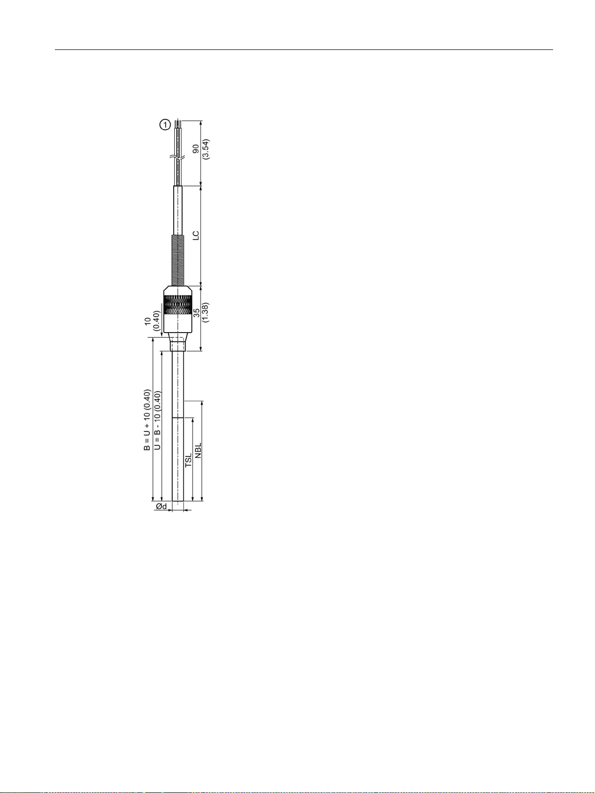
Dimension drawings
9.2
SITRANS TS100
①
TS100 mineral-insulated version
∅d
External diameter of measuring insert (6 (0.24))
B
Length of measuring insert
LC
Cable length
NBL
Non bendable length
TSL
Temperature sensitive length
U
Mounting length
9.2 SITRANS TS100
Figure 9-1 Dimensional drawings SITRANS TS100 - dimensions in mm (inch)
TS100/TS200/TS300/TS500/TSinsert/TSthermowell
Compact Operating Instructions, 01/2018, A5E03920348-AE
69
Page 70
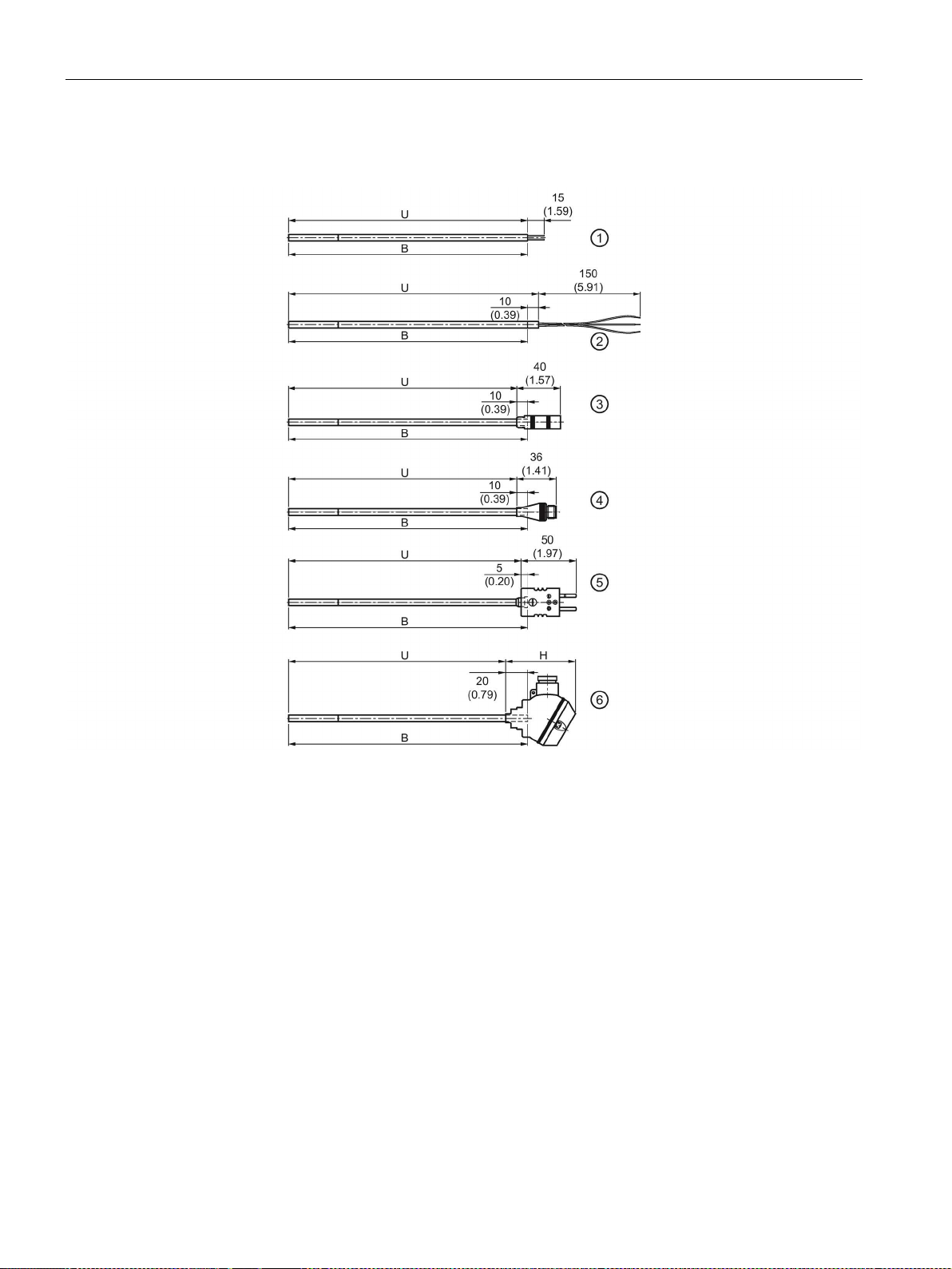
Dimension drawings
9.3
SITRANS TS200
B
Length of measuring insert
U
Mounting length
H
Height of head
①
Basic sensor
U = B
②
Flying Leads
U = B + 10 (0.39)
③
Coupling LEMO 1S
U = B - 10 (0.39)
④
M12 connector
U = B - 10 (0.39)
⑤
Thermocouple coupling
U = B - 5 (0.20)
⑥
Miniature connection head
U = B - 20 (0.79)
9.3 SITRANS TS200
Figure 9-2 Dimensional drawings SITRANS TS200 - dimensions in mm (inch)
TS100/TS200/TS300/TS500/TSinsert/TSthermowell
70 Compact Operating Instructions, 01/2018, A5E03920348-AE
Page 71
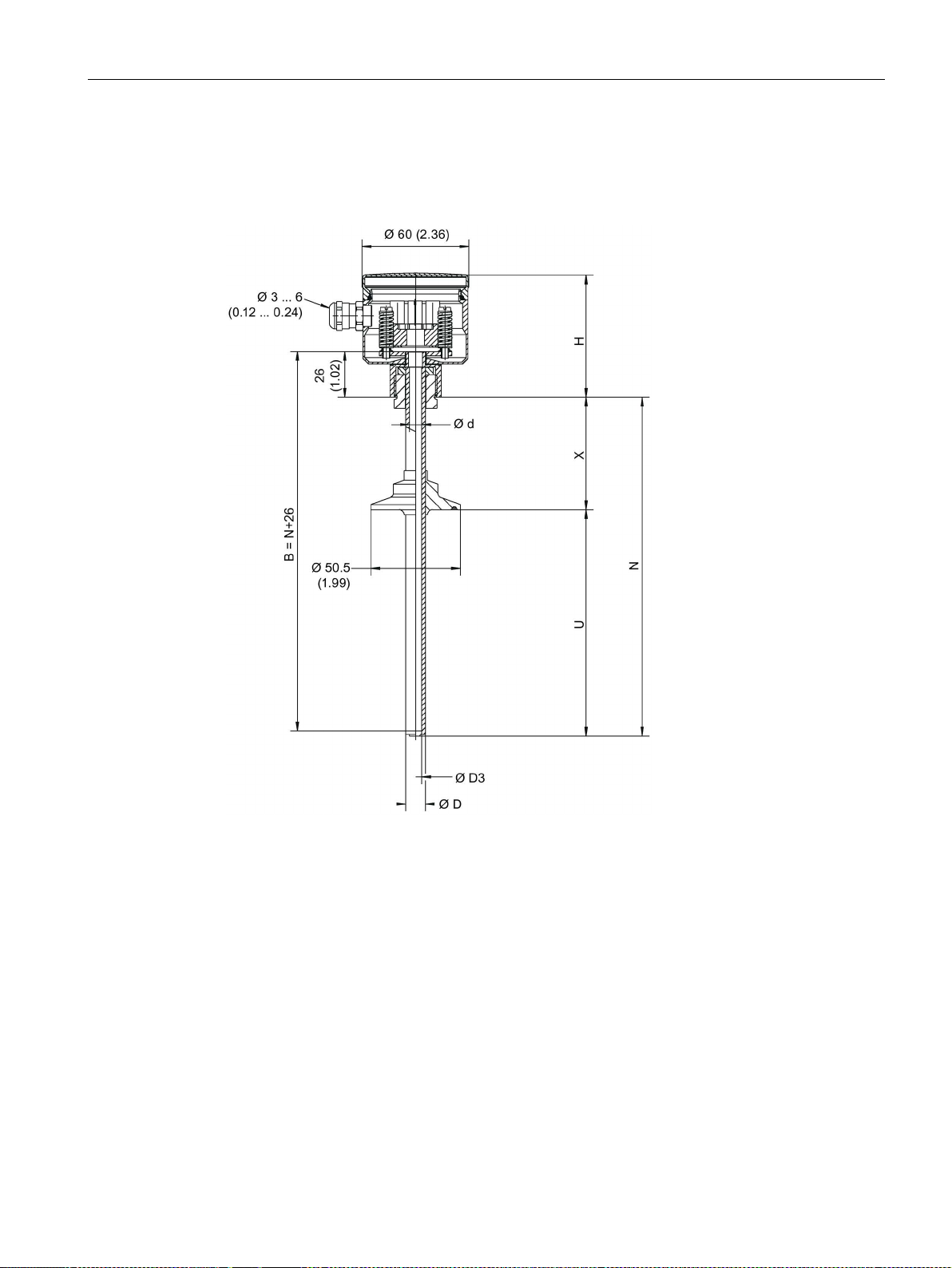
Dimension drawings
9.4
SITRANS TS300
SITRANS TS300 Modular:
B
Length of measuring insert
H
Height of head
∅d
External diameter of measuring insert
N
Nominal length
options)
tions)
9.4 SITRANS TS300
∅D External diameter of process connection U Mounting length (see process connection
∅D3 Internal diameter of protective tube X Extension (see process connection op-
Figure 9-3 Dimensions in mm (inch)
TS100/TS200/TS300/TS500/TSinsert/TSthermowell
Compact Operating Instructions, 01/2018, A5E03920348-AE
71
Page 72
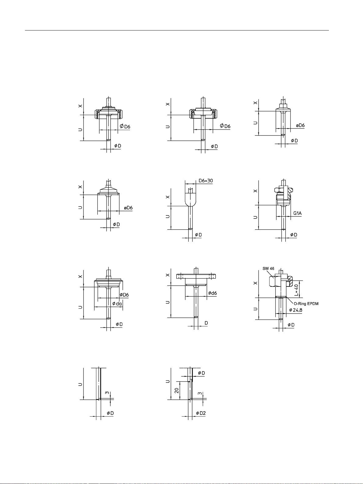
Dimension drawings
Process connection options:
tapered coupling with
groove union nut aseptic
design per DIN 11864-1
tapered coupling with
groove union nut per
DIN 11851
tri-clamp connection
clamp connection per
DIN 32676 or ISO 2852
thermowell with welding
ball 30 x 40 mm
G1A dead-zone free (conical metal taper)
Varivent connection
NEUMO connection
connection per INGOLD
DN 25 with coupling nut
neck tube according to DIN 43772
model 2
similar model 3 reduced
tip
9.4 SITRANS TS300
TS100/TS200/TS300/TS500/TSinsert/TSthermowell
72 Compact Operating Instructions, 01/2018, A5E03920348-AE
Page 73
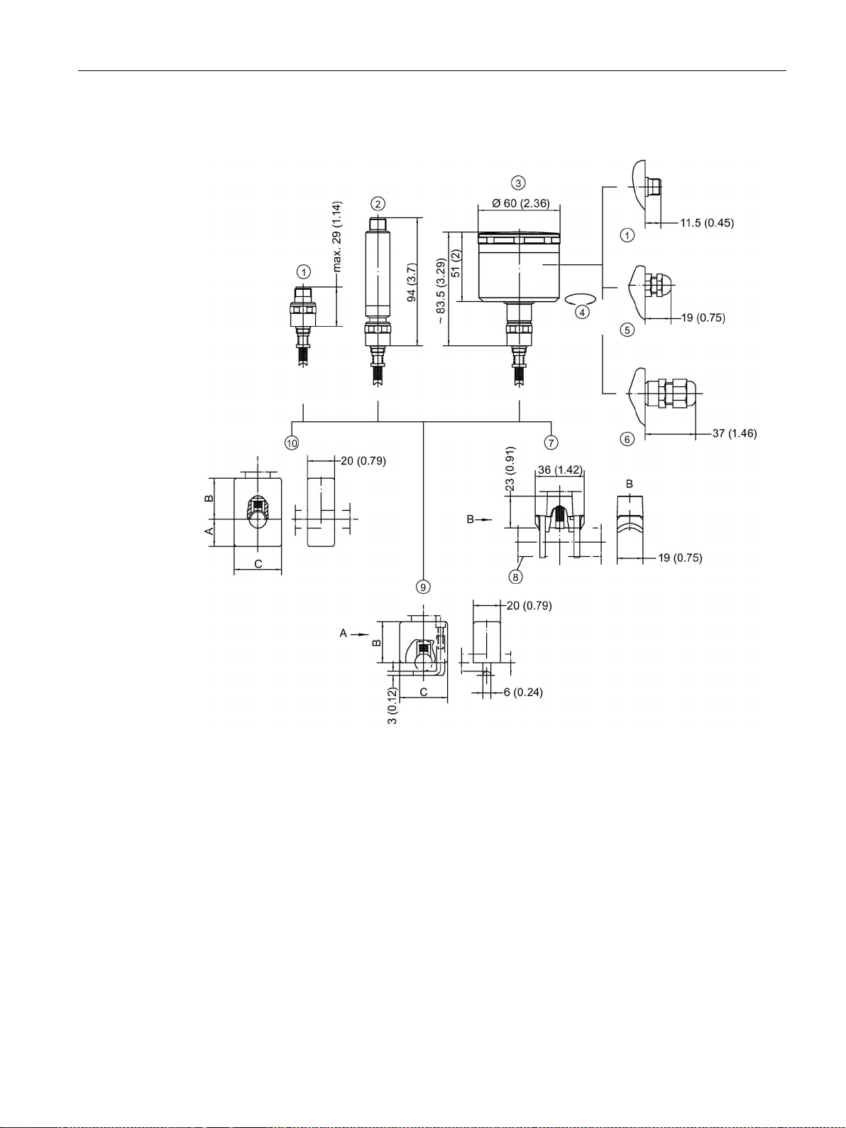
Dimension drawings
SITRANS TS300 Clamp-on:
①
circular connector M12 x 1
⑥
cable connection M16 x 1,5 cable ∅4, 5-10
②
M12 x 1
⑦
③
housing
⑧
④
ble
⑨
⑤
∅3-6, 5
⑩
pipe ∅
A B C
4-17.2 (0.16 -
0.68)
18-38 (0.71 - 1.5)
30
40
70
38.1-57 (1.5 -
2.24)
9.4 SITRANS TS300
transmitter with circular connector
stainless steel connection head
electrical connection ± 170° rotata-
cable connection M12 x 1,5 cable
TS100/TS200/TS300/TS500/TSinsert/TSthermowell
Compact Operating Instructions, 01/2018, A5E03920348-AE
clamping shoe for pipe ≥ ∅10 - ∼∅300
example ∅21 (0.83)
clamping bracket for pipe ∅4-17, 2
clamping block for pipe ∅4-57
20 30 35
40 50 85
73
Page 74

Dimension drawings
9.4 SITRANS TS300
Figure 9-4 Dimensions in mm (inch)
TS100/TS200/TS300/TS500/TSinsert/TSthermowell
74 Compact Operating Instructions, 01/2018, A5E03920348-AE
Page 75
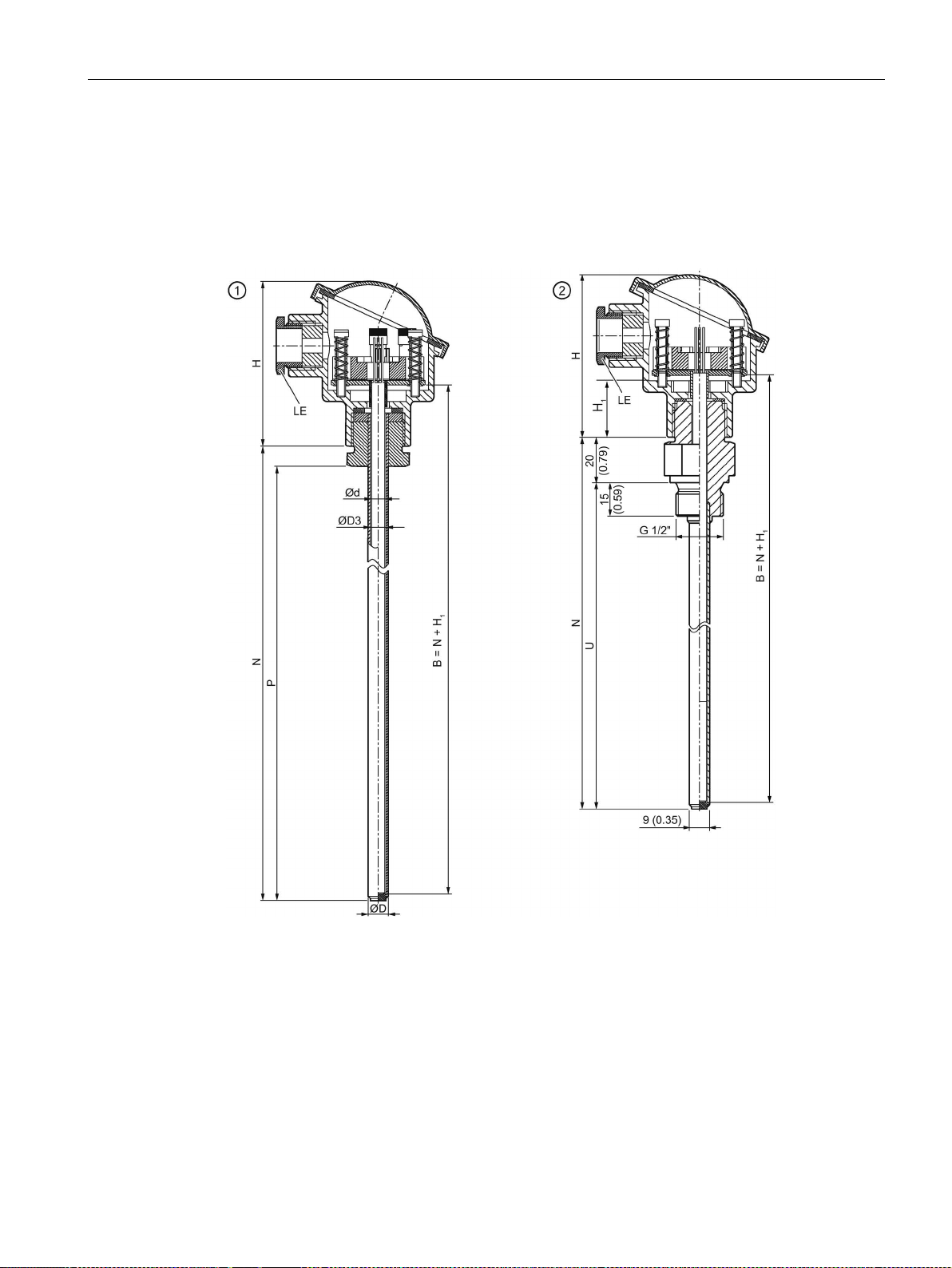
Dimension drawings
9.5
SITRANS TS500
9.5.1
SITRANS TS500, types 2 and 2N
①
Type 2, pipe version without process connection
②
Type 2N, pipe version with screw-in nipple
Type Bxx: 26 (1.02)
∅d
External diameter of measuring insert
K
Penetration depth
∅D
To ①: External diameter of fixing point (6 (0.24))
LE
Cable inlet
∅D
To ②: External diameter of process connection
N
Nominal length
∅D3
Internal diameter of protective tube
P
Space for process connection
E
Thread dimension of process connection
U
Mounting length
H
Height of head
X
Extension
9.5 SITRANS TS500
B Length of measuring insert H1 Type Axx: 41 (1.61)
TS100/TS200/TS300/TS500/TSinsert/TSthermowell
Compact Operating Instructions, 01/2018, A5E03920348-AE
75
Page 76
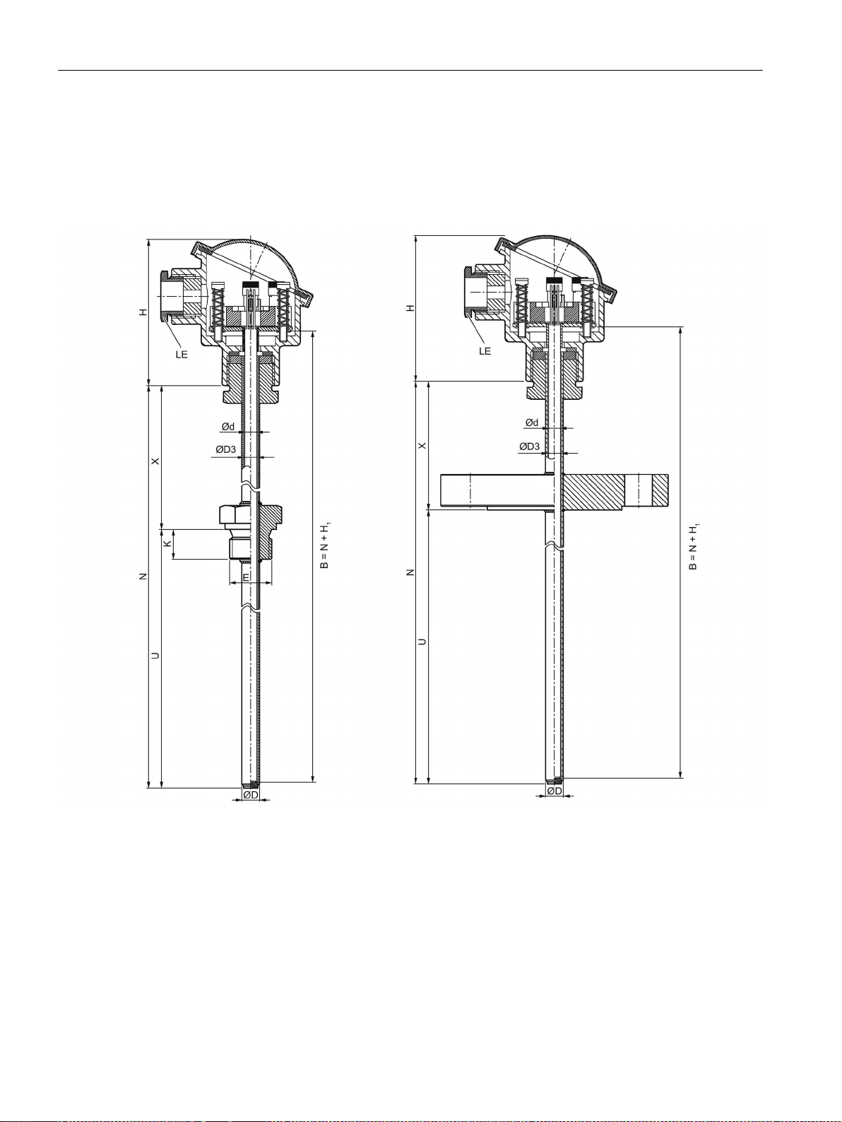
Dimension drawings
9.5.2
SITRANS TS500, types 2G and 2F
①
Type 2G, pipe version with screw-in nipple and extension
②
Type 2F, pipe version with flange and extension
Type Bxx: 26 (1.02)
∅d
External diameter of measuring insert (6 (0.24))
K
Penetration depth
∅D
External diameter of process connection
LE
Cable inlet
∅D3
Internal diameter of protective tube
N
Nominal length
E
Thread dimension of process connection
U
Mounting length
H
Height of head
X
Extension
9.5 SITRANS TS500
Figure 9-5 Dimensional drawings SITRANS TS500, types 2 and 2N - dimensions in mm (inch)
B Length of measuring insert H1 Type Axx: 41 (1.61)
Figure 9-6 Dimensional drawings SITRANS TS500, types 2G and 2F - dimensions in mm (inch)
TS100/TS200/TS300/TS500/TSinsert/TSthermowell
76 Compact Operating Instructions, 01/2018, A5E03920348-AE
Page 77
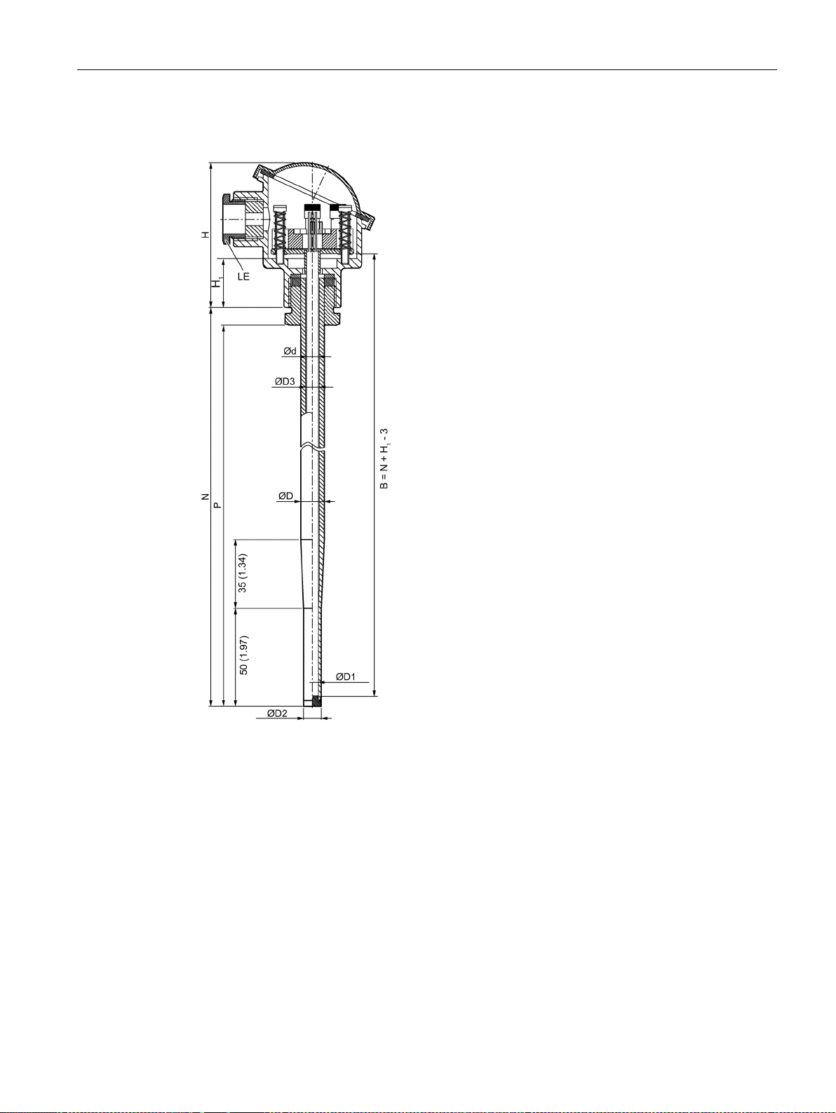
Dimension drawings
9.5.3
SITRANS TS500, type 3
①
Type 3, fast pipe version without process connection
B
Length of measuring insert (European)
H
Height of head
(6 (0.24))
Type Bxx: 26 (1.02)
∅D
External diameter of fixing point
LE
Cable inlet
∅D1
Internal diameter of tip
N
Nominal length
∅D2
External diameter of tip
P
Space for process connection
∅D3
Internal diameter of protective tube
9.5 SITRANS TS500
∅d External diameter of measuring insert
Figure 9-7 Dimensional drawing SITRANS TS500, type 3 - dimensions in mm (inch)
TS100/TS200/TS300/TS500/TSinsert/TSthermowell
Compact Operating Instructions, 01/2018, A5E03920348-AE
H1 Type Axx: 41 (1.61)
77
Page 78
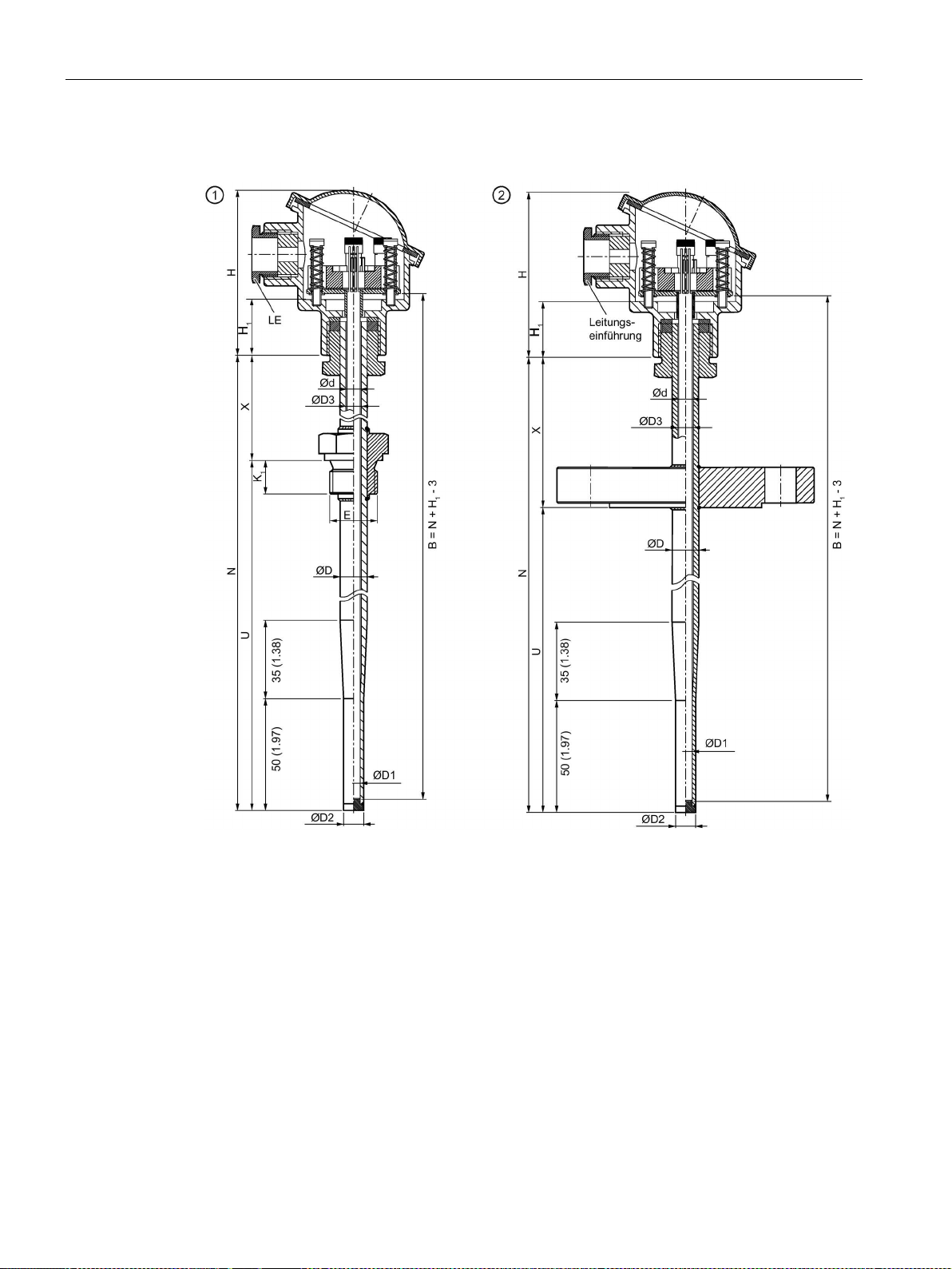
Dimension drawings
9.5.4
SITRANS TS500, types 3G and 3F
①
Type 3G, fast pipe version with screw-in nipple and extension
②
Type 3F, fast pipe version with flange and extension
Type Bxx: 26 (1.02)
∅d
External diameter of measuring insert (6 (0.24))
H
Height of head
∅D
External diameter of process connection
K
Penetration depth
∅D1
Internal diameter of tip
LE
Cable inlet
∅D2
External diameter of tip
N
Nominal length
∅D3
Internal diameter of protective tube
U
Mounting length
E
Thread dimension of process connection
X
Extension
9.5 SITRANS TS500
B Length of measuring insert (European) H1 Type Axx: 41 (1.61)
Figure 9-8 Dimensional drawings SITRANS TS500, types 3G and 3F
TS100/TS200/TS300/TS500/TSinsert/TSthermowell
78 Compact Operating Instructions, 01/2018, A5E03920348-AE
Page 79
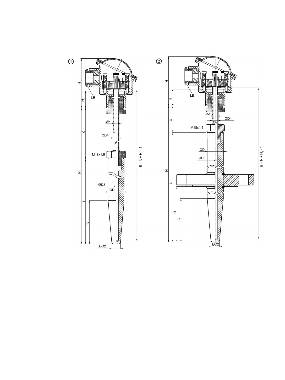
Dimension drawings
9.5.5
SITRANS TS500, types 4 and 4F
①
Type 4, full material version, with extension
②
Type 4F, full material version, with flange and extension
nection
C
Cone length = U
min
H
Height of head
Type Bxx: 26 (1.02)
∅D
External diameter of process connection
K
Penetration depth
∅D1
Internal diameter of tip
L
Length of protective sleeve
∅D2
External diameter of tip
LE
Cable inlet
∅D3
Internal diameter of protective tube
N
Nominal length
∅D4
External diameter of extension
U
Mounting length
X
Extension
9.5 SITRANS TS500
B Length of measuring insert E Thread dimension of process con-
∅d External diameter of measuring insert (6 (0.24)) H1 Type Axx: 41 (1.61)
TS100/TS200/TS300/TS500/TSinsert/TSthermowell
Compact Operating Instructions, 01/2018, A5E03920348-AE
79
Page 80

Dimension drawings
9.5 SITRANS TS500
Figure 9-9 Dimensional drawings SITRANS TS500, types 4 and 4F - dimensions in mm (inch)
TS100/TS200/TS300/TS500/TSinsert/TSthermowell
80 Compact Operating Instructions, 01/2018, A5E03920348-AE
Page 81
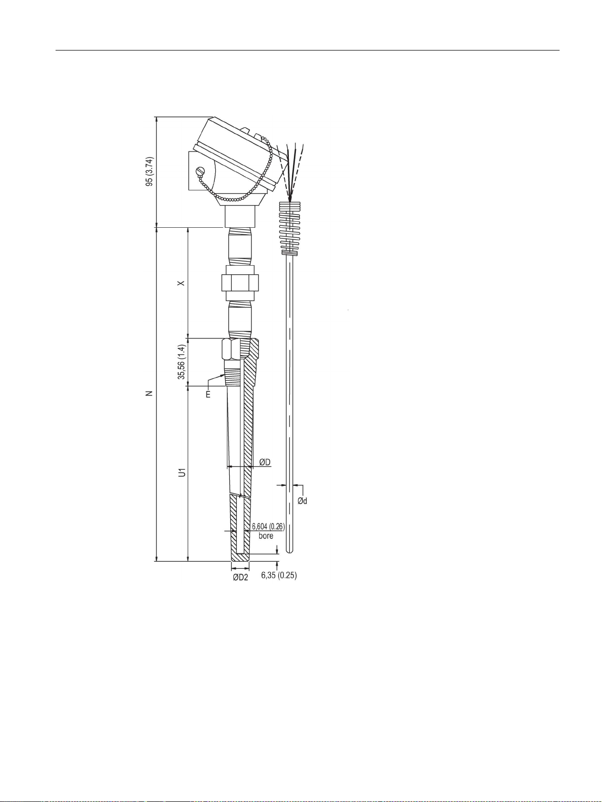
Dimension drawings
9.5.6
SITRANS TS500, type ST, threaded tapered well (7MC65..)
tion
∅D
External diameter of process connection
N
Nominal length
∅D2
External diameter of tip
U1
Unsupported length
X
Extension
9.5 SITRANS TS500
∅d External diameter of measuring insert E Thread dimension of process connec-
Figure 9-10 Dimensional drawings SITRANS TS500, type ST, threaded tapered well - dimensions in
TS100/TS200/TS300/TS500/TSinsert/TSthermowell
Compact Operating Instructions, 01/2018, A5E03920348-AE
mm (inch)
81
Page 82
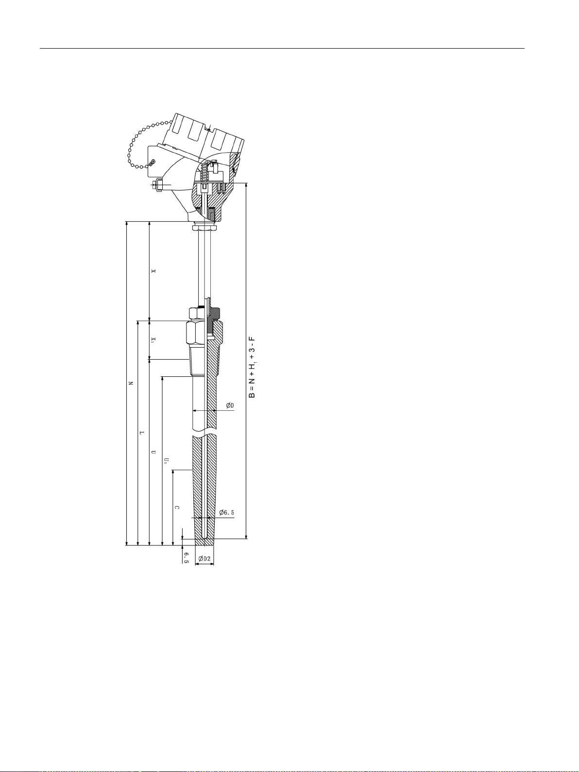
Dimension drawings
9.5.7
SITRANS TS500, type SST, threaded tapered well (7MC55..)
L
Length of thermowell
B
Length of insert
∅D1
External diameter of process connection
N
Nominal length
U
Insertion length
U1
Unsupported length
Type Bxx = 26 (1.02)
X1
Lag length
C
Cone length
F
Thermowell bottom thickness
9.5 SITRANS TS500
∅D2 External diameter of tip
X Extension H1 Head bottom thickness:
TS100/TS200/TS300/TS500/TSinsert/TSthermowell
82 Compact Operating Instructions, 01/2018, A5E03920348-AE
Type Axx = 41 (1.61)
Page 83

Dimension drawings
9.5 SITRANS TS500
Figure 9-11 Dimensional drawings SITRANS TS500, type SST, threaded tapered well (7MC55…) -
dimensions in mm (inch)
TS100/TS200/TS300/TS500/TSinsert/TSthermowell
Compact Operating Instructions, 01/2018, A5E03920348-AE
83
Page 84
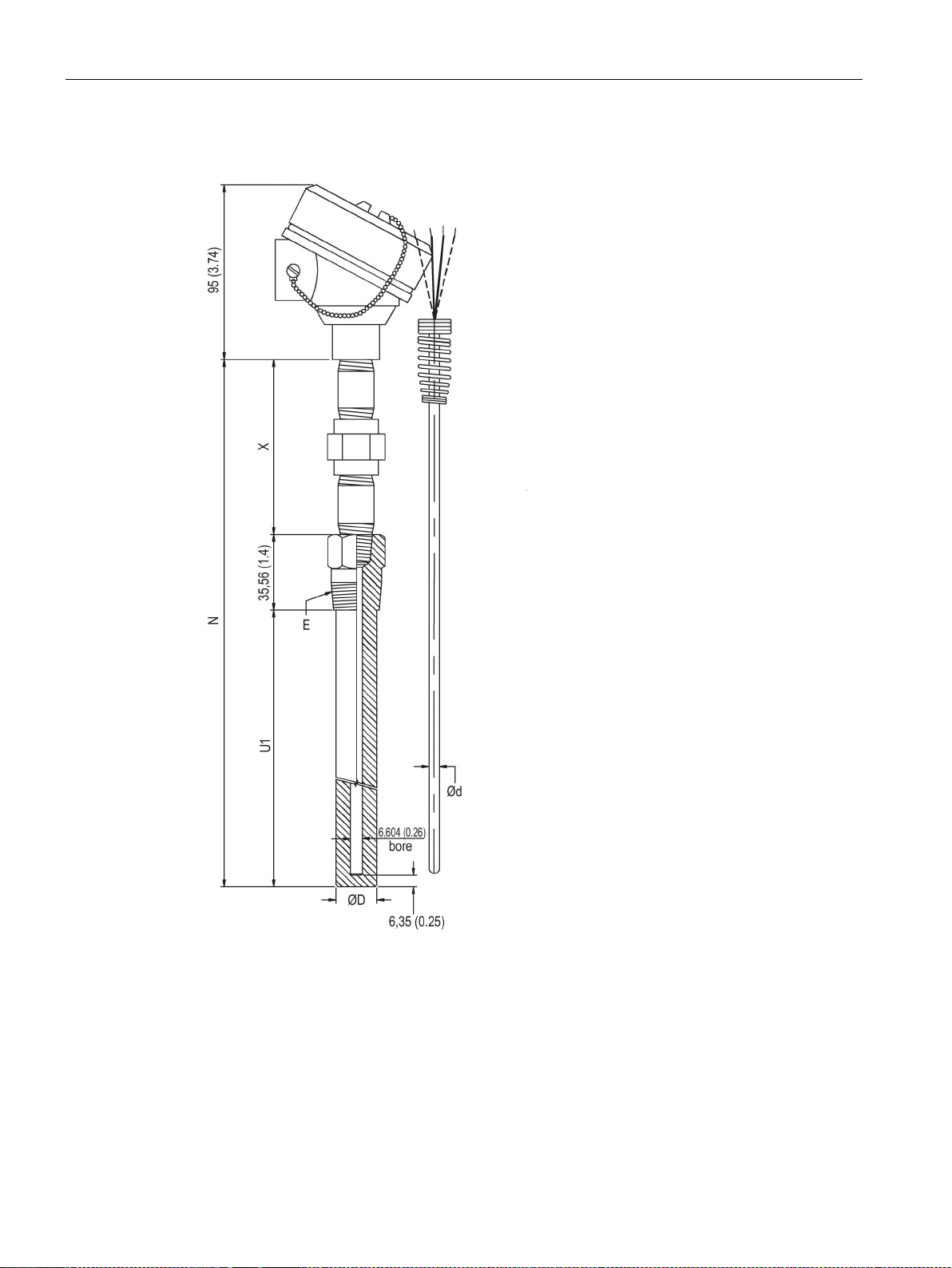
Dimension drawings
9.5.8
SITRANS TS500, type SS, threaded straight well (7MC65..)
tion
∅D
External diameter of process connection
N
Nominal length
X
Extension
U1
Unsupported length
9.5 SITRANS TS500
∅d External diameter of measuring insert E Thread dimension of process connec-
Figure 9-12 Dimensional drawings SITRANS TS500, type SS, threaded straight well - dimensions in
TS100/TS200/TS300/TS500/TSinsert/TSthermowell
84 Compact Operating Instructions, 01/2018, A5E03920348-AE
mm (inch)
Page 85
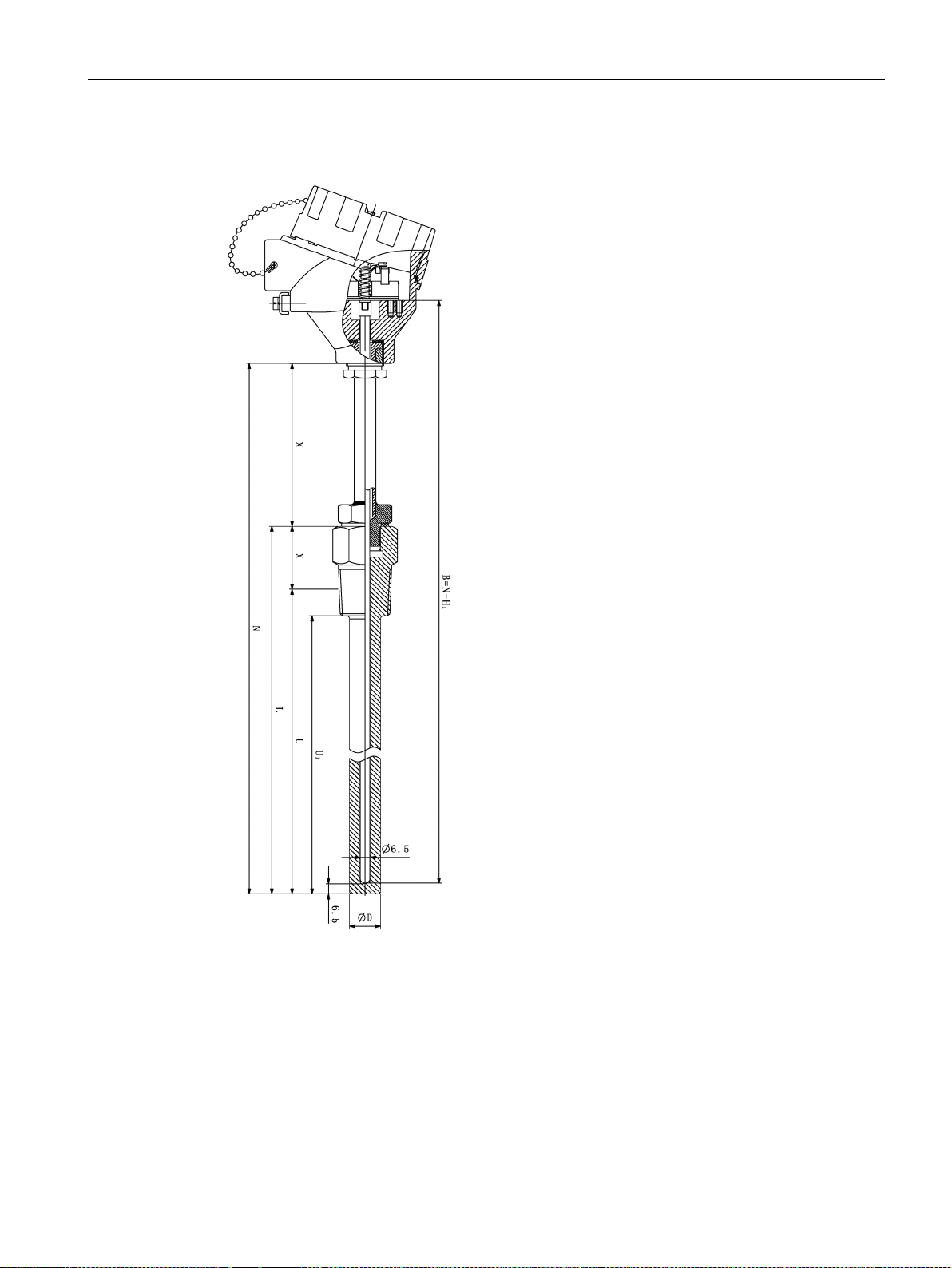
Dimension drawings
9.5.9
SITRANS TS500, type SS, threaded straight well (7MC55..)
L
Length of thermowell
X1
Lag length
Type Bxx = 26 (1.02)
∅D
External diameter of process connection
N
Nominal length
U
Insertion length
U1
Unsupported length
9.5 SITRANS TS500
H1 Head bottom thickness:
X Extension
Figure 9-13 Dimensional drawings SITRANS TS500, type SS, threaded straight well (7MC55…)
TS100/TS200/TS300/TS500/TSinsert/TSthermowell
Compact Operating Instructions, 01/2018, A5E03920348-AE
B Length of measuring insert
Type Axx = 41 (1.61)
85
Page 86
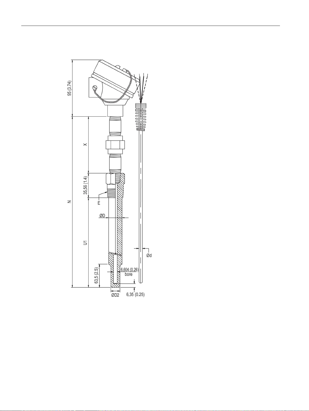
Dimension drawings
9.5.10
SITRANS TS500, type SR, threaded reduced well (7MC65..)
tion
∅D
External diameter of process connection
N
Nominal length
∅D2
External diameter of tip
U1
Unsupported length
X
Extension
9.5 SITRANS TS500
∅d External diameter of measuring insert E Thread dimension of process connec-
Figure 9-14 Dimensional drawings SITRANS TS500, type SR, threaded reduced well - dimensions in
TS100/TS200/TS300/TS500/TSinsert/TSthermowell
86 Compact Operating Instructions, 01/2018, A5E03920348-AE
mm (inch)
Page 87
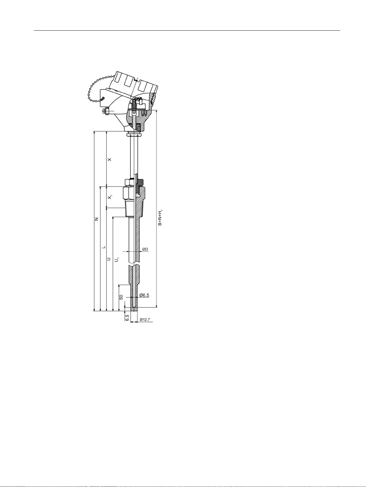
Dimension drawings
9.5.11
SITRANS TS500, type SR, threaded reduced well (7MC55..)
Type Bxx = 26 (1.02)
∅D
External diameter of process connection
N
Nominal length
U
Insertion length
U1
Unsupported length
X1
Lag length
L
Length of thermowell
9.5 SITRANS TS500
H
Head bottom thickness:
1
X Extension
Figure 9-15 Dimensional drawings SITRANS TS500, type SR, threaded reduced well (7MC55…)
TS100/TS200/TS300/TS500/TSinsert/TSthermowell
Compact Operating Instructions, 01/2018, A5E03920348-AE
B Length of measuring insert
Type Axx = 41 (1.61)
87
Page 88
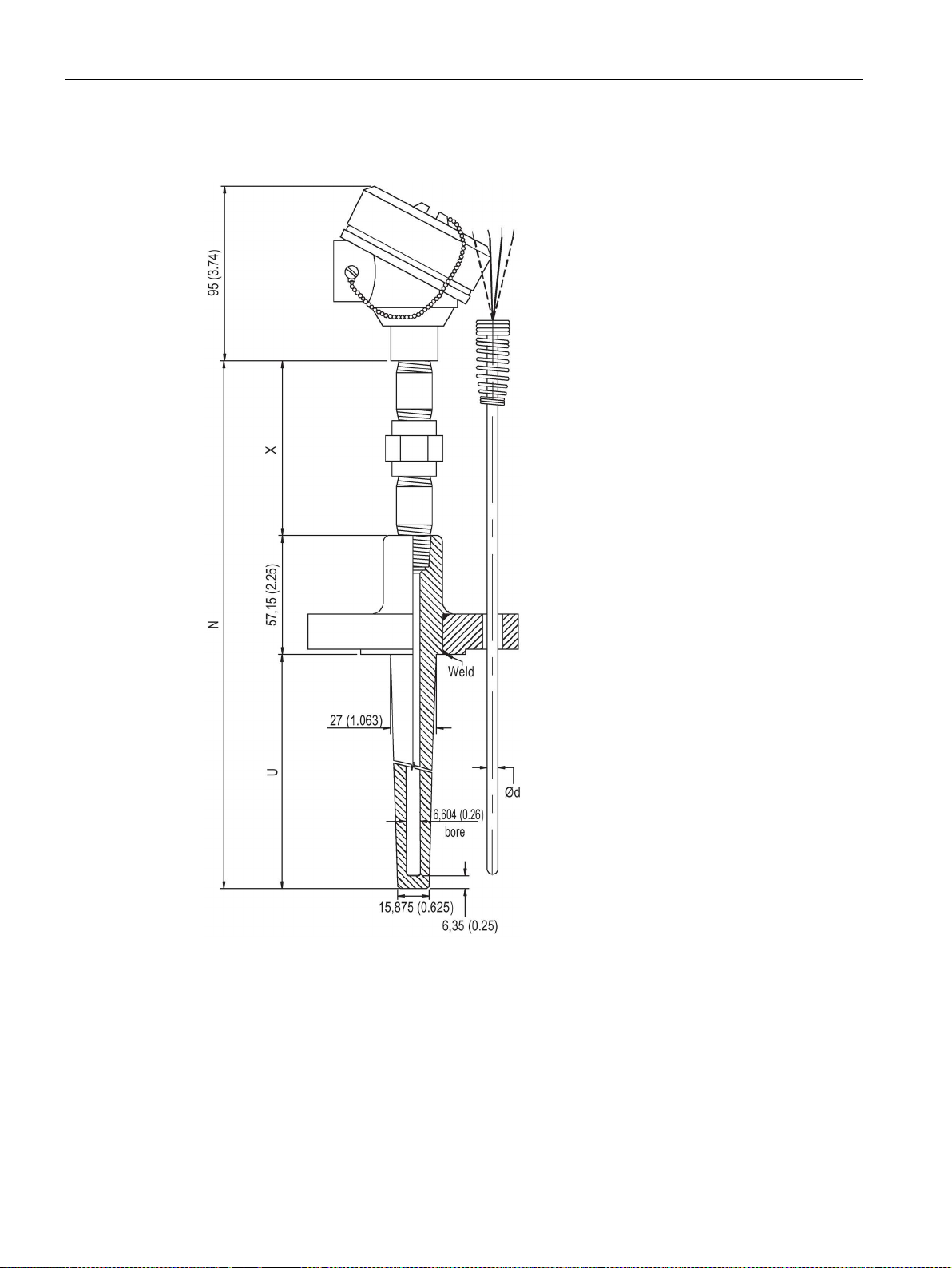
Dimension drawings
9.5.12
SITRANS TS500, type FT, flanged tapered well (7MC65..)
(6 (0.24))
X
Extension
U
Mounting length
9.5 SITRANS TS500
TS100/TS200/TS300/TS500/TSinsert/TSthermowell
88 Compact Operating Instructions, 01/2018, A5E03920348-AE
∅d External diameter of measuring insert
Figure 9-16 Dimensional drawings SITRANS TS500, type FT, flanged tapered well - dimensions in
mm (inch)
N Nominal length
Page 89
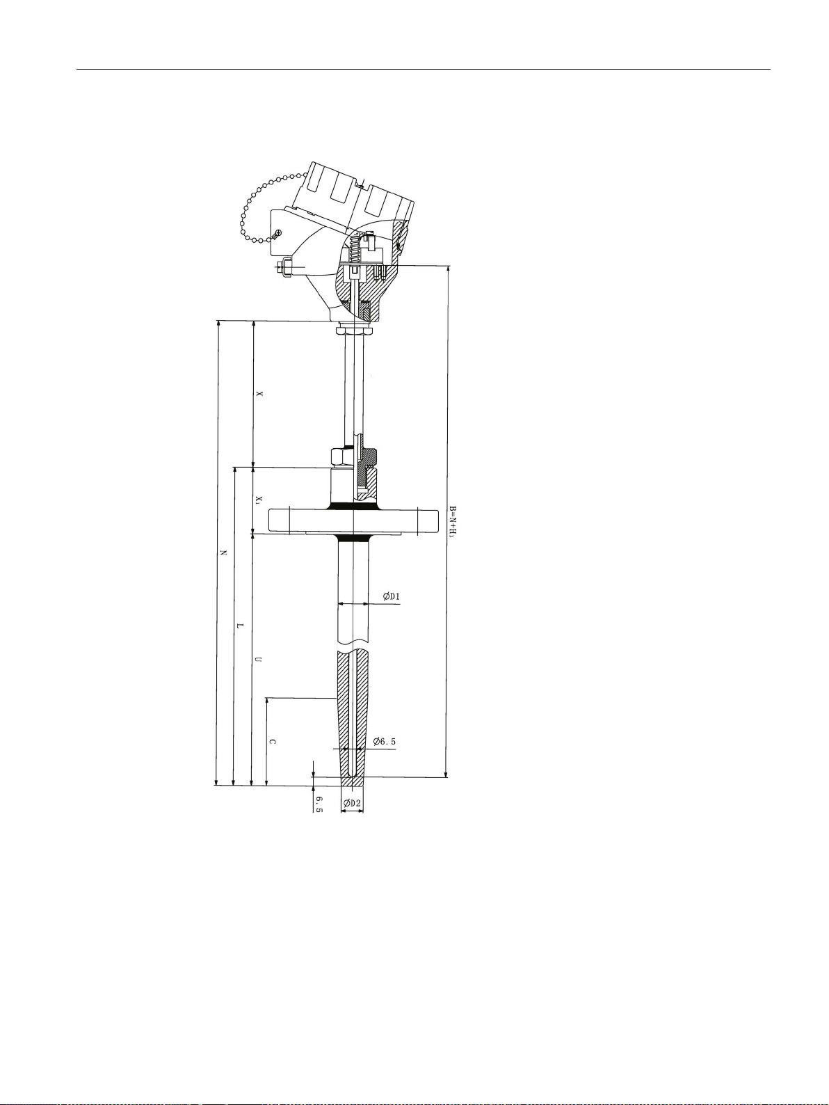
Dimension drawings
9.5.13
SITRANS TS500, type FST, flanged tapered well (7MC55..)
L
Length of thermowell
B
Length of measuring Insert
∅D1
External diameter of process connection
N
Nominal length
∅D2
External diameter of tip
U
Insertion length
Type Bxx = 26 (1.02)
9.5 SITRANS TS500
X Extension length H1 Head bottom thickness
TS100/TS200/TS300/TS500/TSinsert/TSthermowell
Compact Operating Instructions, 01/2018, A5E03920348-AE
Type Axx = 41 (1.61)
89
Page 90

Dimension drawings
X1
Lag lenght
C
Cone Length
9.5 SITRANS TS500
Figure 9-17 Dimensional drawings SITRANS TS500, type FST, flanged tapered well (7MC55…)
TS100/TS200/TS300/TS500/TSinsert/TSthermowell
90 Compact Operating Instructions, 01/2018, A5E03920348-AE
Page 91
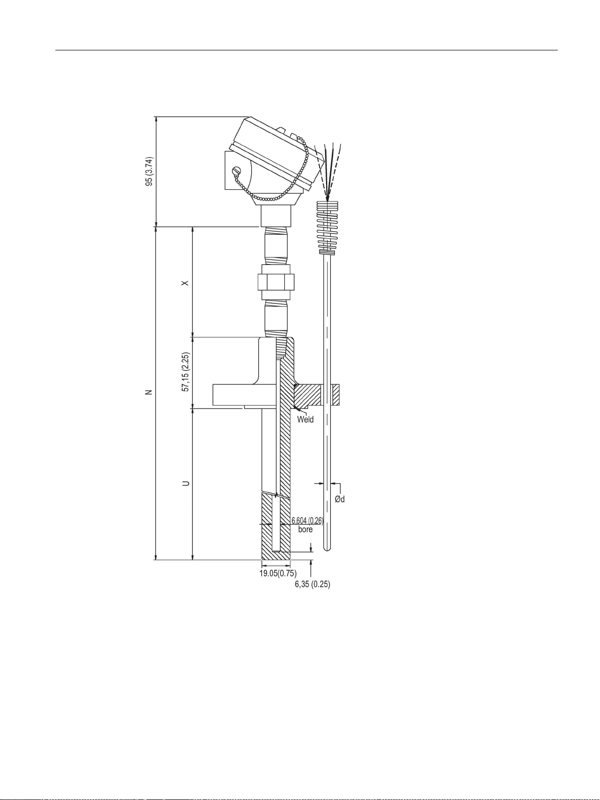
Dimension drawings
9.5.14
SITRANS TS500, type FS, flanged straight well (7MC65..)
(6 (0.24))
X
Extension
U
Mounting length
9.5 SITRANS TS500
TS100/TS200/TS300/TS500/TSinsert/TSthermowell
Compact Operating Instructions, 01/2018, A5E03920348-AE
∅d External diameter of measuring insert
Figure 9-18 Dimensional drawings SITRANS TS500, type FS, flanged straight well - dimensions in
mm (inch)
N Nominal length
91
Page 92
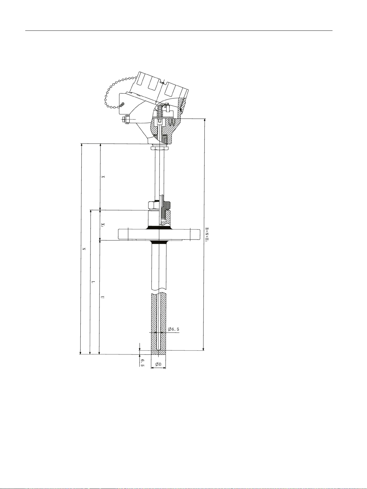
Dimension drawings
9.5.15
SITRANS TS500, type FS, flanged straight well (7MC55..)
∅D
External diameter of measuring insert
N
Nominal length
X
Extension
U
Mounting length
X1
Lag length
B
Lenght of measuring insert
H1
Head bottom thickness
9.5 SITRANS TS500
Figure 9-19 Dimensional drawings SITRANS TS500, type FS, flanged straight well (7MC55…)
TS100/TS200/TS300/TS500/TSinsert/TSthermowell
92 Compact Operating Instructions, 01/2018, A5E03920348-AE
Page 93
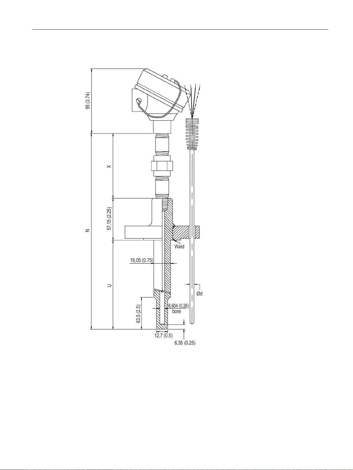
Dimension drawings
9.5.16
SITRANS TS500, type FR, flanged reduced well (7MC65..)
(6 (0.24))
X
Extension
U
Mounting length
9.5 SITRANS TS500
TS100/TS200/TS300/TS500/TSinsert/TSthermowell
Compact Operating Instructions, 01/2018, A5E03920348-AE
∅d External diameter of measuring insert
Figure 9-20 Dimensional drawings SITRANS TS500, type FR, flanged reduced well - dimensions in
mm (inch)
N Nominal length
93
Page 94
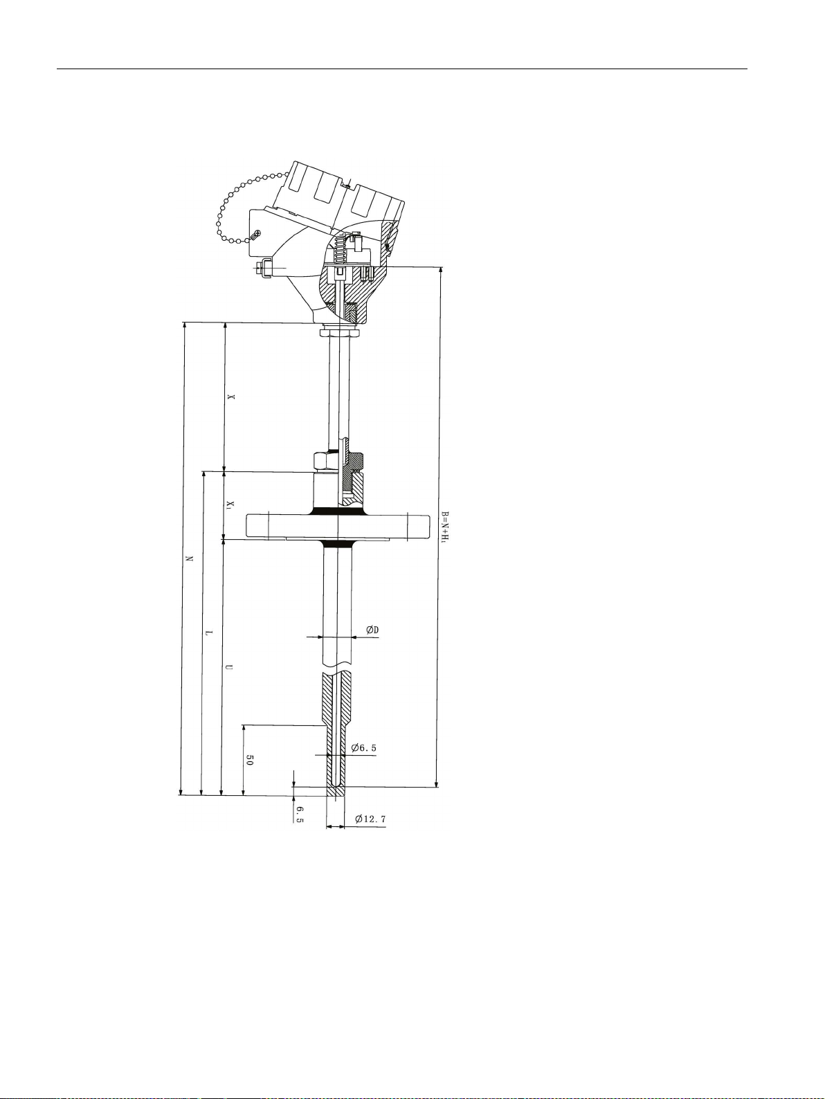
Dimension drawings
9.5.17
SITRANS TS500, type FR, flanged reduced well (7MC55..)
∅D
External diameter of measuring insert
N
Nominal length
X
Extension
U
Mounting length
B
Lenght of measuring insert
H1
Head bottom thickness
9.5 SITRANS TS500
Figure 9-21 Dimensional drawings SITRANS TS500, type FR, flanged reduced well (7MC55…)
TS100/TS200/TS300/TS500/TSinsert/TSthermowell
94 Compact Operating Instructions, 01/2018, A5E03920348-AE
Page 95
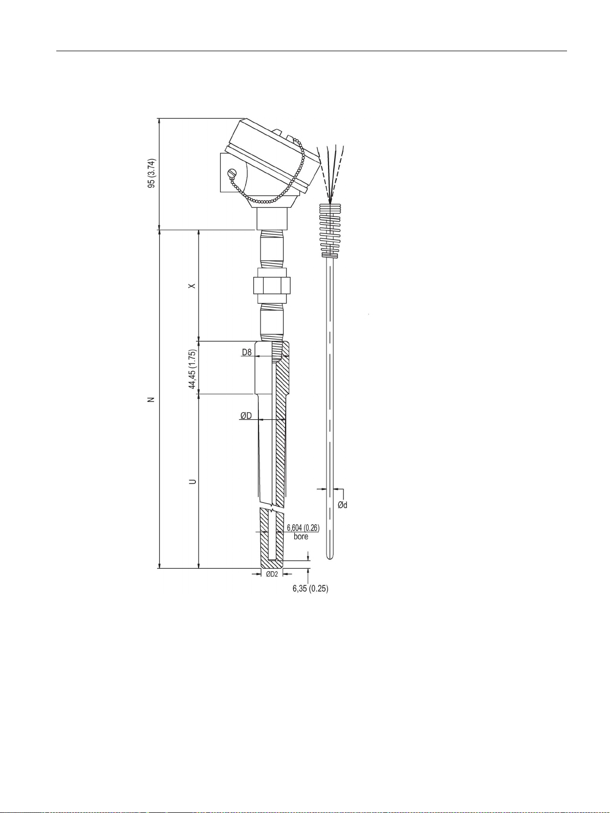
Dimension drawings
9.5.18
SITRANS TS500, type SWT, socket tapered well (7MC65..)
(6 (0.24))
∅D
External diameter of process connection
U
Mounting length
∅D2
External diameter of tip
X
Extension
∅D8
Internal diameter of protective tube
9.5 SITRANS TS500
∅d External diameter of measuring insert
Figure 9-22 Dimensional drawings SITRANS TS500, type SWT, socket tapered well - dimensions in
TS100/TS200/TS300/TS500/TSinsert/TSthermowell
Compact Operating Instructions, 01/2018, A5E03920348-AE
N Nominal length
mm (inch)
95
Page 96
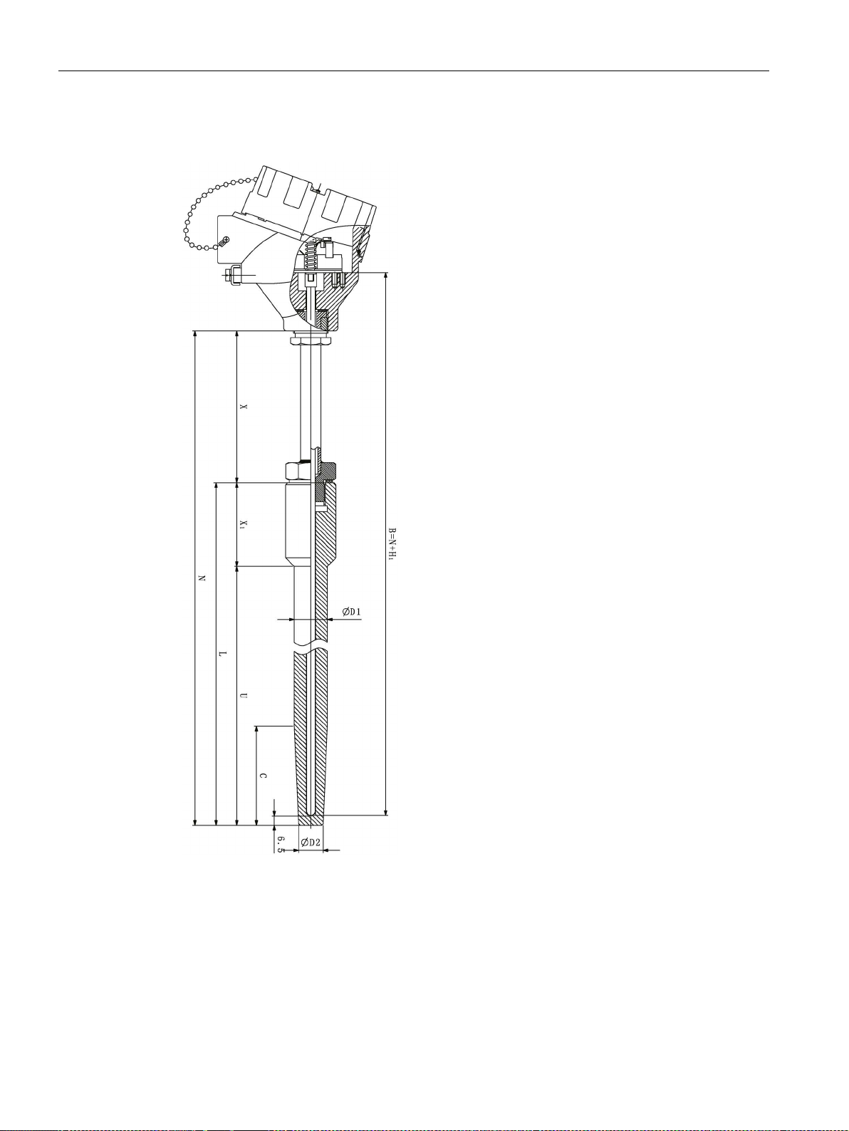
Dimension drawings
9.5.19
SITRANS TS500, type SWST, socket tapered well (7MC55..)
L
Length of thermowell
B
Length of measuring insert
∅D1
External diameter of process connection
N
Nominal length
∅D2
External diameter of tip
U
Insertion length
Type Bxx = 26 (1.02)
X1
Lag lenght
C
Cone Length
9.5 SITRANS TS500
X Extension length H1 Head bottom thickness
TS100/TS200/TS300/TS500/TSinsert/TSthermowell
96 Compact Operating Instructions, 01/2018, A5E03920348-AE
Type Axx = 41 (1.61)
Page 97

Dimension drawings
9.5 SITRANS TS500
Figure 9-23 Dimensional drawings SITRANS TS500, type SWST, socket tapered well (7MC55…)
TS100/TS200/TS300/TS500/TSinsert/TSthermowell
Compact Operating Instructions, 01/2018, A5E03920348-AE
97
Page 98
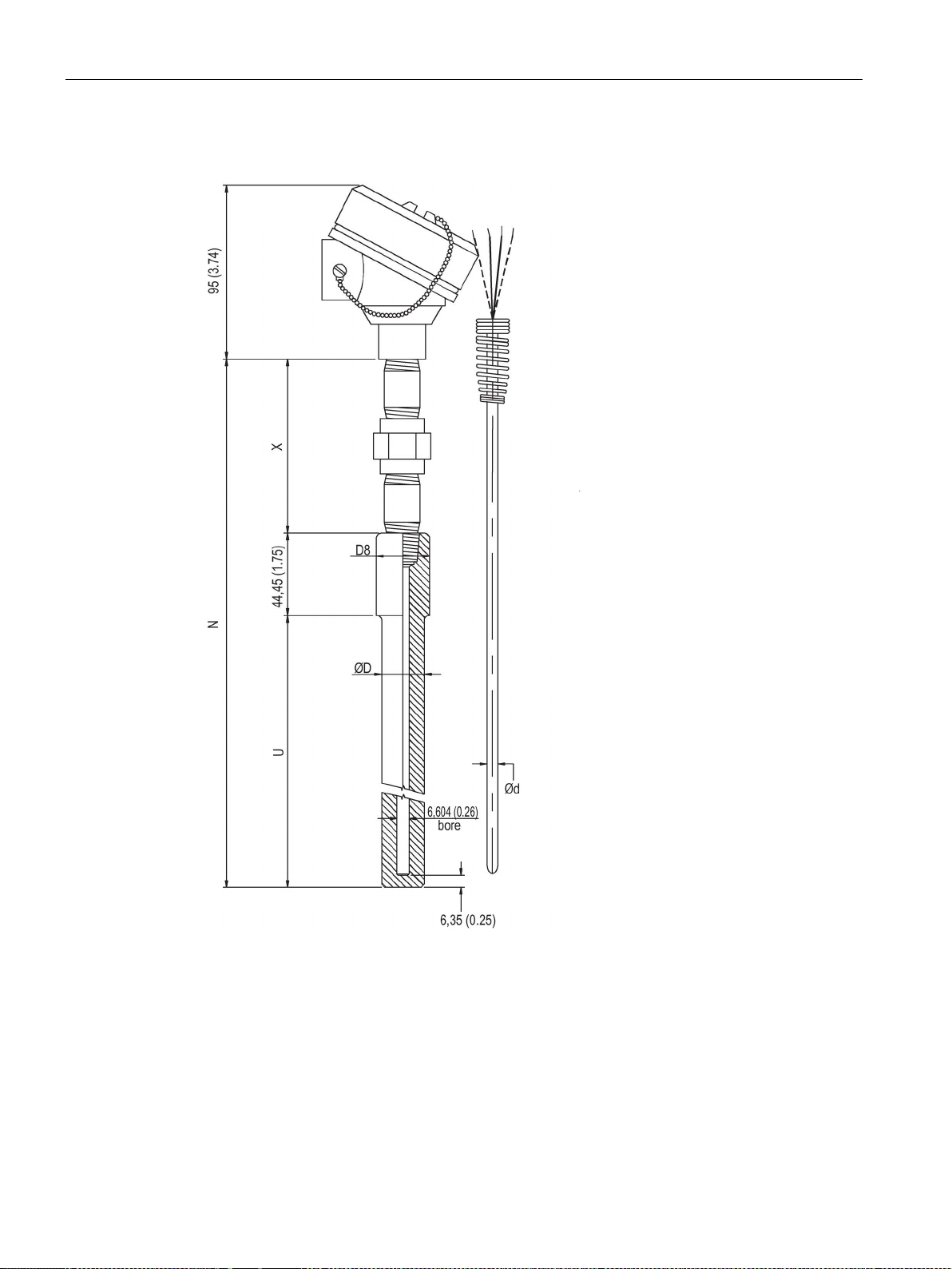
Dimension drawings
9.5.20
SITRANS TS500, type SWS, socket straight well (7MC65..)
(6 (0.24))
∅D
External diameter of process connection
U
Mounting length
∅D2
External diameter of tip
X
Extension
∅D8
Internal diameter of protective tube
9.5 SITRANS TS500
∅d External diameter of measuring insert
Figure 9-24 Dimensional drawings SITRANS TS500, type SWS, socket straight well - dimensions in
TS100/TS200/TS300/TS500/TSinsert/TSthermowell
98 Compact Operating Instructions, 01/2018, A5E03920348-AE
N Nominal length
mm (inch)
Page 99
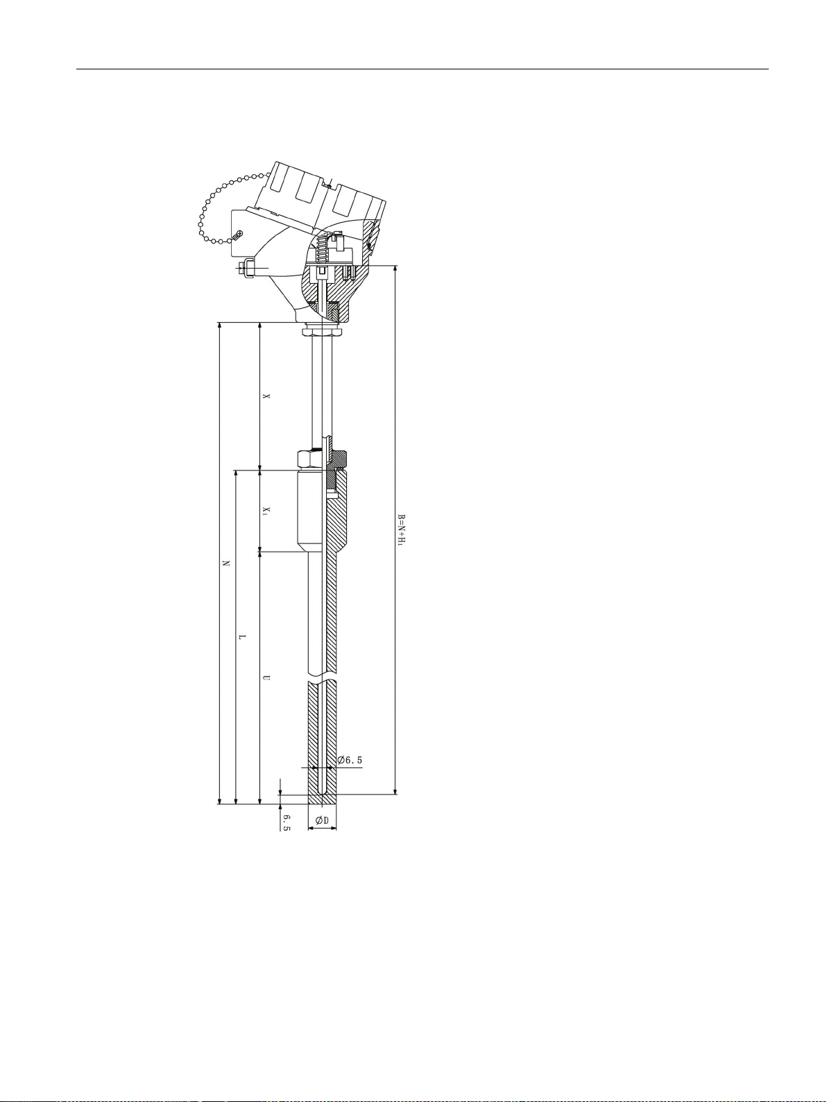
Dimension drawings
9.5.21
SITRANS TS500, type SWS, socket straight well (7MC55..)
∅D
External diameter of process connection
U
Mounting length
B
Length of measuring Insert
X
Extension
Type Bxx = 26 (1.02)
N
Nominal length
L
Length of thermowell
9.5 SITRANS TS500
H1 Head bottom thickness:
Figure 9-25 Dimensional drawings SITRANS TS500, type SWS, socket straight well (7MC55…)
TS100/TS200/TS300/TS500/TSinsert/TSthermowell
Compact Operating Instructions, 01/2018, A5E03920348-AE
X1 Lag length
Type Axx = 41 (1.61)
99
Page 100
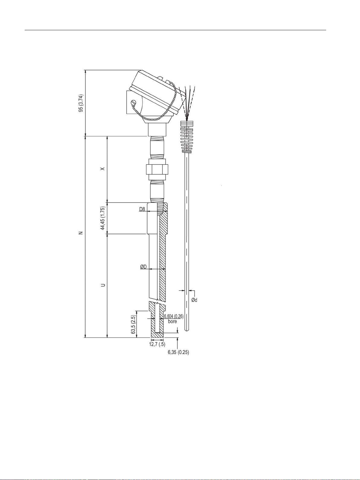
Dimension drawings
9.5.22
SITRANS TS500, type SWR, socket reduced well (7MC65..)
(6 (0.24))
∅D
External diameter of process connection
U
Mounting length
∅D8
Internal diameter of tip
X
Extension
9.5 SITRANS TS500
∅d External diameter of measuring insert
Figure 9-26 Dimensional drawings SITRANS TS500, type SWR, socket reduced well - dimensions in
TS100/TS200/TS300/TS500/TSinsert/TSthermowell
100 Compact Operating Instructions, 01/2018, A5E03920348-AE
N Nominal length
mm (inch)
 Loading...