

Siemens SITRANS RD300 Operating Instructions Manual
DIN-Rail Mounting Kit
SITRANS RD300
Operating Instructions • 05/2013
SITRANS

SITRAN SITRANSS
Safety Guidelines: Warning notices must be observed to ensure personal safety as well as that of
others, and to protect the product and the connected equipment. These warning notices are
accompanied by a clarification of the level of caution to be observed.
Qualified Personnel: This device/system may only be set up and operated in conjunction with this
manual. Qualified personnel are only authorized to install and operate this equipment in accordance
with established safety practices and standards.
Unit Repair and Excluded Liability:
The user is responsible for all changes and repairs made to the device by the user or the user’s
agent.
All new components are to be provided by Siemens Milltronics Process Instruments.
Restrict repair to faulty components only.
Do not reuse faulty components.
WARNING: Cardboard shipping package provides limited humidity and moisture protection.
This product can only function properly and safely if it is correctly transported, stored,
installed, set up, operated, and maintained.
This product is intended for use in industrial areas. Operation of this equipment in a
residential area may cause interference to several frequency based communications.
Note: Always use product in accordance with specifications.
Copyright Siemens AG 2013. All Rights
Reserved
This document is available in bound version
and in electronic version. We encourage users
to purchase authorized bound manuals, or to
view electronic versions as designed and
authored by Siemens Milltronics Process
Instruments. Siemens Milltronics Process
Instruments will not be responsible for the
contents of partial or whole reproductions of
either bound or electronic versions.
MILLTRONICS
Contact SMPI Technical Publications at the
following address:
Technical Publications
Siemens AG
Siemens Milltronics Process Instruments
1954 Technology Drive, P.O. Box 4225
Peterborough, Ontario, Canada, K9J 7B1
Email: techpubs.smpi@siemens.com
For a selection of Siemens Milltronics level measurement manuals, go to:
For a selection of Siemens Milltronics weighing manuals, go to:
®
is a registered trademark of Siemens Milltronics Process Instruments.
www. siemens.com/processautomation. Under Process Instrumentation, select Level
Measurement and then go to the manual archive listed under the product family.
www. siemens.com/processautomation. Under Weighing Technology, select Continuous
Weighing Systems and then go to the manual archive listed under the product family.
Disclaimer of Liability
While we have verified the contents of this
manual for agreement with the instrumentation
described, variations remain possible. Thus we
cannot guarantee full agreement. The contents
of this manual are regularly reviewed and
corrections are included in subsequent editions.
We welcome all suggestions for improvement.
Technical data subject to change.
European Authorized Representative
Siemens AG
Industry Sector
76181 Karlsruhe
Deutschland
© Siemens AG 2013
The Manual
This manual provides instruction for the DIN-rail mounting kit. The
manual provides information on the following
Installation requirements
OVERVIEW
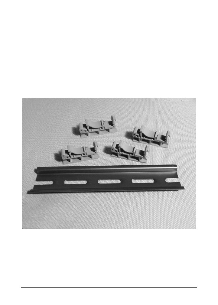
The mounting kit includes (1) 6" length of DIN-rail, (4) mounting clips,
and this instruction sheet. It contains enough parts to mount 2 modules.
Please read the instructions thoroughly before proceeding.
Page 1 DIN-RAIL KIT - OPERATING INSTRUCTIONS A5E31979181
SITRAN SITRANSS
INSTRUCTIONS
Step 1
Mounting the DIN-rail clips to the module
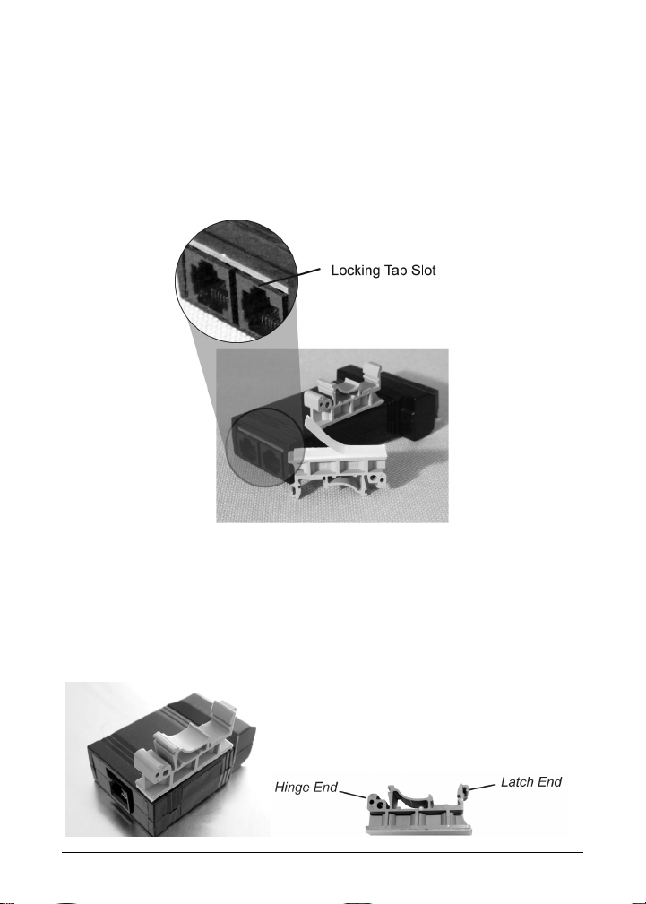
Place the expansion module on a flat surface with the bottom surface
facing up. The bottom surface can be identified as the surface closest to
the locking tab slot on the modular connector.
.
Expansion Module Example
Peel the protective layer off of the adhesive tape on the bottom of one of
the mounting clips. With the hinge end of the clip (see below) facing the
end of the module with the communications connector, align the clip
along the long (side) edge of the module and centered lengthwise within
the flat surface of the module.
A5E31979181 DIN-RAIL KIT - OPERATING INSTRUCTIONS Page 2
 Loading...