

Siemens SITRANS RD200 Operating Instructions Manual
Communications and Displays
SITRANS RD200
Operating Instructions 11/2012
SITRANS

Safety Guidelines: Warning notices must be observed to ensure personal safety as well as that of
others, and to protect the product and the connected equipment. These warning notices are
accompanied by a clarification of the level of caution to be observed.
Qualified Personnel: This device/system may only be set up and operated in conjunction with this
manual. Qualified personnel are only authorized to install and operate this equipment in accordance with
established safety practices and standards.
Unit Repair and Excluded Liability:
The user is responsible for all changes and repairs made to the device by the user or the user’s
agent.
All new components are to be provided by Siemens Milltronics Process Instruments.
Restrict repair to faulty components only.
Do not reuse faulty components.
Warning: Cardboard shipping package provides limited humidity and moisture protection. This product
can only function properly and safely if it is correctly transported, stored, installed, set up, operated, and
maintained.
This product is intended for use in industrial areas. Operation of this equipment in a residential area
may cause interference to several frequency based communications.
Note: Always use product in accordance with specifications.
Copyright Siemens AG 2012. All Rights
Disclaimer of Liability
Reserved
This document is available in bound version and in
electronic version. We encourage users to purchase
authorized bound manuals, or to view electronic
versions as designed and authored by Siemens
Milltronics Process Instruments. Siemens Milltronics
Process Instruments will not be responsible for the
contents of partial or whole reproductions of either
bound or electronic versions.
While we have verified the contents of this
manual for agreement with the
instrumentation described, variations remain
possible. Thus we cannot guarantee full
agreement. The contents of this manual are
regularly reviewed and corrections are
included in subsequent editions. We welcome
all suggestions for improvement.
Technical data subject to change.
MILLTRONICS®is a registered trademark of Siemens Milltronics Process Instruments.
Contact SMPI Technical Publications European Authorized Representative
at the following address:
Technical Publications Siemens AG
Siemens AG Industry Sector
Siemens Milltronics Process Instruments 76181 Karlsruhe
1954 Technology Drive, P.O. Box 4225 Deutschland
Peterborough, Ontario, Canada, K9J 7B1
Email: techpubs.smpi@siemens.com
For a selection of Siemens Milltronics level measurement manuals, go to:
www. siemens.com/processautomation. Under Process Instrumentation, select
Measurement
For a selection of Siemens Milltronics weighing manuals, go to:
www. siemens.com/processautomation. Under Weighing Technology, select
Weighing Systems
and then go to the manual archive listed under the product family.
and then go to the manual archive listed under the product family.
Level
Continuous
© Siemens AG 2012

Table of Contents
Table of Contents
SITRANS RD200 .................................................................................................................1
SITRANS RD200 ....................................................................................................................................1
Safety Notes ...........................................................................................................................................1
The Manual ............................................................................................................................................2
Specifications ....................................................................................................................3
Power............................................................................................................................................. 3
Mounting....................................................................................................................................... 3
Memory ......................................................................................................................................... 4
Programming................................................................................................................................ 4
Display ........................................................................................................................................... 4
Outputs........................................................................................................................................... 4
Serial Communications.............................................................................................................. 5
Inputs.............................................................................................................................................. 6
Enclosure ...................................................................................................................................... 6
Weight............................................................................................................................................ 6
Approvals...................................................................................................................................... 6
Dimensions .........................................................................................................................7
RD200 Meter Dimensions - Side View .............................................................................................7
RD200 Case Dimensions - Top View ................................................................................................7
Installation ..........................................................................................................................9
Unpacking ...............................................................................................................................................9
Panel Mounting Instructions ..............................................................................................................9
Connections .........................................................................................................................................11
Connector Labeling ...................................................................................................................11
Power Connections ..................................................................................................................11
Signal Connections ...................................................................................................................12
Serial Communication ..............................................................................................................15
Relays and 24 V Output Connections ...................................................................................15
4 to 20 mA Output and Input Signal Connections ..............................................................15
mmmmm
Setup ..................................................................................................................................17
Front panel buttons and status LED indicators ............................................................................17
Display functions and messages ....................................................................................................18
Main menu ............................................................................................................................................20
Setting numeric values ......................................................................................................................20
Setting up the meter (SEtu) ..............................................................................................................20
Setting the input signal (inPt) .................................................................................................21
Setting the decimal point (dEc.P) ..........................................................................................23
Setting the temperature scale (F C) ......................................................................................23
Setting relay operation (rELY) ................................................................................................24
Relay and Alarm Operation ....................................................................................................27
Scaling the 4 to 20 mA analog output (Aout) ......................................................................33
Program sensor break output value (SEbr) ........................................................................34
Analog output when display is out of range .......................................................................34
Programming the meter (ProG) .......................................................................................................35
Scaling the 4 to 20 mA analog input (ScAL) ........................................................................35
i

mmmmm
Calibrating the SITRANS RD200 (CAL) .................................................................................36
Recalibrating temperature inputs (CAL) ..............................................................................37
Recalibrating process inputs (ICAL) .....................................................................................38
Security .................................................................................................................................................39
Locking the meter by setting a password (PASS) ............................................................39
Unlocking the meter (unLC) ....................................................................................................39
Advanced Features Menu ................................................................................................................41
Advanced features menu and display messages .............................................................41
Table o f Cont en ts
Offset adjustment (Adj) ............................................................................................................42
Noise filter (FLtr) ........................................................................................................................43
Noise filter bypass (bYPS) ......................................................................................................43
Serial communications (SErL) ................................................................................................44
Select menu (SELc) ...................................................................................................................45
SITRANS RD Software .............................................................................................................47
Meter copy function (CoPY) ...................................................................................................47
Internal calibration (ICAL) .......................................................................................................48
Troubleshooting .........................................................................................................................50
Operation ..........................................................................................................................53
Front panel buttons operation .........................................................................................................53
Maximum/Minimum readings ..........................................................................................................53
Appendix A - Factory Defaults ......................................................................................55
Appendix B - Troubleshooting Tips .............................................................................57
Appendix C - Quick User Interface Reference Guide ...............................................59
Appendix D - Serial Communication Protocol (PDC) ...............................................61
SITRANS RD200 PDC .........................................................................................................................61
Table of Commands ..................................................................................................................62
Command Packet Format ........................................................................................................63
Reply Packet Format ................................................................................................................64
Read Only Commands ..............................................................................................................64
No-Data Commands .................................................................................................................67
Read/Write Commands ...........................................................................................................69
Appendix E - Modbus Register Tables ........................................................................85
Register Overview ..............................................................................................................................85
Tables ....................................................................................................................................................95
Input configuration ....................................................................................................................95
Decimal Point for RD200 ..........................................................................................................96
Relay Configuration ..................................................................................................................96
4-20 mA Output Modes ...........................................................................................................97
Available Register Table .........................................................................................................97
ii
SITRANS RD200
SITRANS RD200
SITRANS RD200 is a universal input, panel mount remote digital display for process
instrumentation.
It accepts a single input of current, voltage, thermocouple, or RTD signals, and the four
front panel buttons make the setup and programming an easy task.
The isolated 24 V DC transmitter power (optional) can be used to power the input
transmitter, the 4 to 20 mA output, or other devices.
Two relays (optional) can be used for alarm indication or process control applications,
such as alternating pump control.
4-20 mA isolated output and Modbus® RTU serial communication options make
SITRANS RD200 an excellent addition to any system.
Safety Notes
Special attention must be paid to warnings and notes highlighted from the rest of the text
by grey boxes.
CAUTION: relates to the caution symbol on the product, and means
that failure to observe the necessary precautions can result in
electric shock.
WARNING: relates to a caution symbol on the product, and means
that failure to observe the necessary precautions can result in
death, serious injury, and/or considerable material damage.
SITRANS RD200
mmmmm
WARNING: means that failure to observe the necessary precautions
can result in death, serious injury, and/or considerable material
damage.
CAUTION: means that failure to observe the necessary precautions can
result in considerable material damage.
Note: means important information about the product or that part of the operating
manual.
7ML19985JS01 SITRANS RD200 – OPERATING INSTRUCTIONS Page 1

The Manual
This manual provides instructions for the SITRANS RD200 remote display. The manual is
designed to help you get the most out of your Remote Display, and it provides information
on the following:
• Product specifications
• Outline diagrams
• Installation requirements
• Wiring diagrams
• How to program the unit
• Principles of operation
• Troubleshooting tips
• Factory defaults
• Quick user reference
mmmmm
If you have any questions, comments, or suggestions about the manual contents, please
email us at techpubs.smpi@siemens.com
.
SITRANS RD200
For the complete library of Siemens Milltronics manuals, go to www.siemens.com/
processautomation.
Page 2 SITRANS RD200 – OPERATING INSTRUCTIONS 7ML19985JS01

Specifications
Power
Input voltage option 1
• 85 to 265 V AC, 50/60 Hz; 90 to 265 V DC, 20 W max.
• UL Recognized, 5 A max, slow blow
• May share one 5 A fuse among up to 6 meters
Input voltage option 2
• 12 to 36 V DC, 12 to 24 V AC, 6 W max.
• UL Recognized, 5 A max, slow blow
• May share one 5 A fuse among up to 6 meters
Transmitter power supply
One or two isolated transmitter power supplies (optional)
• Single power supply: one 24 V DC ± 10% @ 200 mA maximum
• Dual power supplies: one 24 V DC ± 10% @ 200 mA maximum, and
one 24 V DC ± 10% @ 40 mA maximum
External loop power supply
• 35 V DC maximum
Specifications
mmmmm
Input impedance
• Voltage ranges: greater than 1 MΩ
• Current ranges: 50 - 100 Ω (depending on resettable fuse impedance)
Output loop resistance
• 24 V DC 10 to 700 Ω maximum
• 35 V DC (external) 100 to 1200 Ω maximum
Mounting
Location
• Indoor/outdoor
• Panel mount 1/8 DIN
• Two panel mounting bracket assemblies provided
Ambient temperature
• Operating temperature range: 0 to +65 °C (0 to +149 °F)
• Storage temperature range: -40 to +85 °C (-40 to +185 °F)
Relative humidity
• Relative humidity: 0 to 90% non-condensing
7ML19985JS01 SITRANS RD200 – OPERATING INSTRUCTIONS Page 3

Installation category
•II
Memory
• Non-volatile
• Stores settings for minimum of ten years if power is lost
Programming
Primary
• Front panel
Secondary
• Meter Copy
• PC with SITRANS RD Software
Display
• 14 mm (0.56") high, red LED
• Four digits (-1999 to 9999), automatic lead zero blanking
• Eight intensity levels
• 2x option: 30.5 mm (1.20") high, red LED
Update Rate
mmmmm
• Process/RTD: 3.7 to 5/second
• Thermocouple: 1.8 to 2.5/second
Specifications
Overange
• Display flashes 9999
Underange
• Display flashes -1999
Outputs
mA Analog
• 4 to 20 mA
• Isolated (optional)
Relays
1
• 2 SPDT Form C relays, 3A (optional)
• Auto initializing
• All relays rated 3A @ 30 V DC or 3A @ 250 V AC, non-inductive
1.
All relays are certified only for use with equipment that fails in a state at or
under the rated maximums of the relays.
Page 4 SITRANS RD200 – OPERATING INSTRUCTIONS 7ML19985JS01

Control Relays
• Pump alternation
• On and off time delay
• Fail-safe or non fail-safe
• Front panel ACK or PC
Alarm Relay
• High or low alarm
• 0 to 100% deadband, user selectable
• Auto and manual reset via front panel or PC
• Latch or non-latch
Accuracy
• ±0.1% FS ±0.004 mA
Serial Communications
Note: The RD200 does not support 8N1. It will be fixed to 8N2 when parity setting
"None" is selected.
Connections
•PDC standard
• RS-232 or RS-422/485 running Modbus®RTU and ASCII via RJ-11 connector
Setup
• Meter address
• PDC protocol: 0 to 99
• Modbus protocol: 1 to 247
•Baud rate
• 300 to 19200 bps
• Transmit time delay
• Programmable between 0 and 199 ms or transmitter always on for RS-422
communication
•Data
• 8 bit (1 start bit, 1 stop bit)
•Parity
• None, even, or odd (Modbus only; PDC protocol does not use parity)
• Byte-to-Byte timeout
• 0.01 to 2.54 sec (Modbus only)
• Turn around delay
• Less than 2 ms (fixed)
Refer to
Modbus Register Tables
Appendix D - Serial Communication Protocol (PDC)
on page 85 for details.
on page 61 and
Specifications
mmmmm
Appendix E -
Software
• SITRANS RD Software
7ML19985JS01 SITRANS RD200 – OPERATING INSTRUCTIONS Page 5

Inputs
Process (field selectable)
• ±20 mA DC (4 to 20 mA, 0 to 20 mA)
• ±10 V DC (1 to 5 V, 0 to 5 V, 0 to 10 V)
Temperature (field selectable)
Thermocouple temperature:
• Type J, K, E, T, Type T using 0.1 ° display resolution
RTD temperature:
•100 Ω RTD
Accuracy
•Process
• ±0.05% of span ±1 count, square root: 10 to 100% FS
• Thermocouple temperature
• Type J: ±1 °C in range -50 to +750 °C (±2 °F in range -58 to +1382 °F)
•Type K: ±1 °C in range -50 to +1260 °C (±2 °F in range -58 to +2300 °F)
• Type E: ±1 °C in range -50 to +870 °C (±2 °F in range -58 to +1578 °F)
•Type T: ±1 °C in range -180 to +371 °C (±2 °F in range -292 to +700 °F)
• Type T, 0.1 °Res: ±1 °C in range -180.0 to +371 °C (±1.8 °F in range -199.9 to
+700 °F)
• RTD temperature
•100 Ω RTD: ±1 °C in range -200 to +750 °C (±1 °F in range -328 to +1382 °F)
mmmmm
Specifications
Enclosure
• High impact plastic, UL 94V-0
• Color: gray
• Degree of protection: front panel Type 4X, NEMA 4X, IP65; panel gasket provided
• 62 mm x 119 mm x 106 mm (2.45" x 4.68" x 4.19") (H x W x D)
• Optional thermoplastic, stainless steel, steel, for 1-6 meters (all with UL Listing and
CSA Certification)
• Optional polycarbonate for 1 meter [available with optional zinc plated or stainless
steel 2" (5.08 cm) mounting kits]
Weight
• 269 g (9.5 oz) (including options)
Approvals
•CE
•UL
•
UL
C
Note: Testing was conducted on SITRANS RD200 meters installed through the covers
of grounded metal enclosures with cable shields grounded at the point of entry
representing installations designed to optimize EMC performance.
Page 6 SITRANS RD200 – OPERATING INSTRUCTIONS 7ML19985JS01
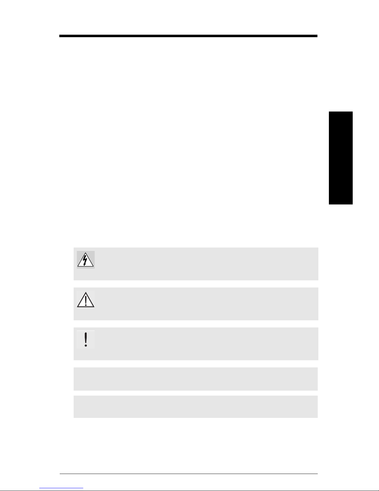
Dimensions
45 mm
(1.76")
62 mm
(2.45")
15 mm
(0.59")
81 mm
(3.2")
91 mm
(3.6")
Screw terminal connector
[0.5 Nm (4.5 lb/in)
tightening torque]
64 mm
(2.5")
119 mm
(4.68")
92 mm
(3.61")
RD200 Meter Dimensions - Side View
RD200 Case Dimensions - Top View
7ML19985JS01 SITRANS RD200 – OPERATING INSTRUCTIONS Page 7
Dimensions
mmmmm

Notes
mmmmm
Dimensions
Page 8 SITRANS RD200 – OPERATING INSTRUCTIONS 7ML19985JS01

Installation
WARNING: Risk of electrical shock.
WARNING: Hazardous voltages exist within enclosure. Installation
and service should be performed only by trained service personnel.
CAUTION: Read complete instructions prior to installation and operation
of the meter.
Notes:
• There is no need to remove the meter from its case to complete the
installation, wiring, and setup of the meter.
• Installation must only be performed by qualified personnel, and in
accordance with local governing regulations.
Unpacking
Remove the meter from box. Inspect the packaging and contents for damage. Report
damages, if any, to the carrier.
If any part is missing or the meter malfunctions, please contact your local Siemens
representative for assistance.
Panel Mounting Instructions
1. Prepare a standard 1/8 DIN panel cutout – 92 mm x 45 mm (3.622 " x 1.772 ").
• Clearance: allow at least 102 mm (4 ") behind the panel for wiring
• Panel thickness: 1.0 mm to 6.4 mm (0.04 " to 0.25")
• Recommended minimum panel thickness to maintain Type 4X
rating: 1.5 mm (0.06 ") steel panel, 4.1 mm (0.16 ") plastic panel.
Refer to
2. Remove the two mounting brackets provided with the meter. Back off the two
3. Insert meter into the panel cutout.
4. Install mounting brackets and tighten the screws against the panel. To achieve a
Troubleshooting
screws so that there is 6.4 mm (¼ ") or less through the bracket. Slide the bracket
toward the front of the case and remove.
proper seal, tighten the mounting bracket screws evenly until meter is snug to the
panel along its short side. DO NOT OVER TIGHTEN, as the rear of the panel may be
damaged.
on page 50 for more details.
Installation
mmmmm
7ML19985JS01 SITRANS RD200 – OPERATING INSTRUCTIONS Page 9
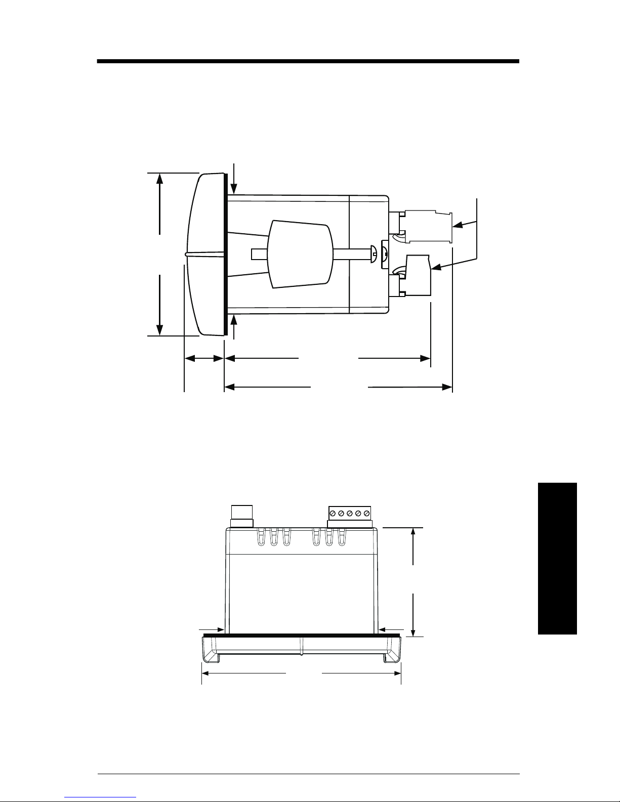
Panel Cutout and Mounting
92 mm (3.622")
square corners to 1.5 mm
(0.060") max radius
A
45 mm
(1.772")
panel cutout
to DIN 43700
B
tolerances:
A: +0.8 mm (+0.032")
-0.0 mm (-0.000 ")
B: +0.6 mm (+0.024")
-0.0 mm (-0.000")
mounting
bracket
mounting
screw
removable
connectors
panel
gasket
mmmmm
Installation
Page 10 SITRANS RD200 – OPERATING INSTRUCTIONS 7ML19985JS01
Connections
!
AC or DC
power
required external fuse: 5
A max, slow blow
power
connector
Notes:
• Verify that all system components are installed in accordance with
instructions.
• All connections are made to removable screw terminal connectors located
at the rear of the meter.
WARNING:
• Use copper wire with +60 °C or +60/75 °C (+140 °F or +140/167 °F)
insulation for all line voltage connections.
• Observe all safety regulations.
• Electrical wiring should be performed in accordance with all
applicable national, state, and local codes to prevent damage to
the meter and ensure personnel safety.
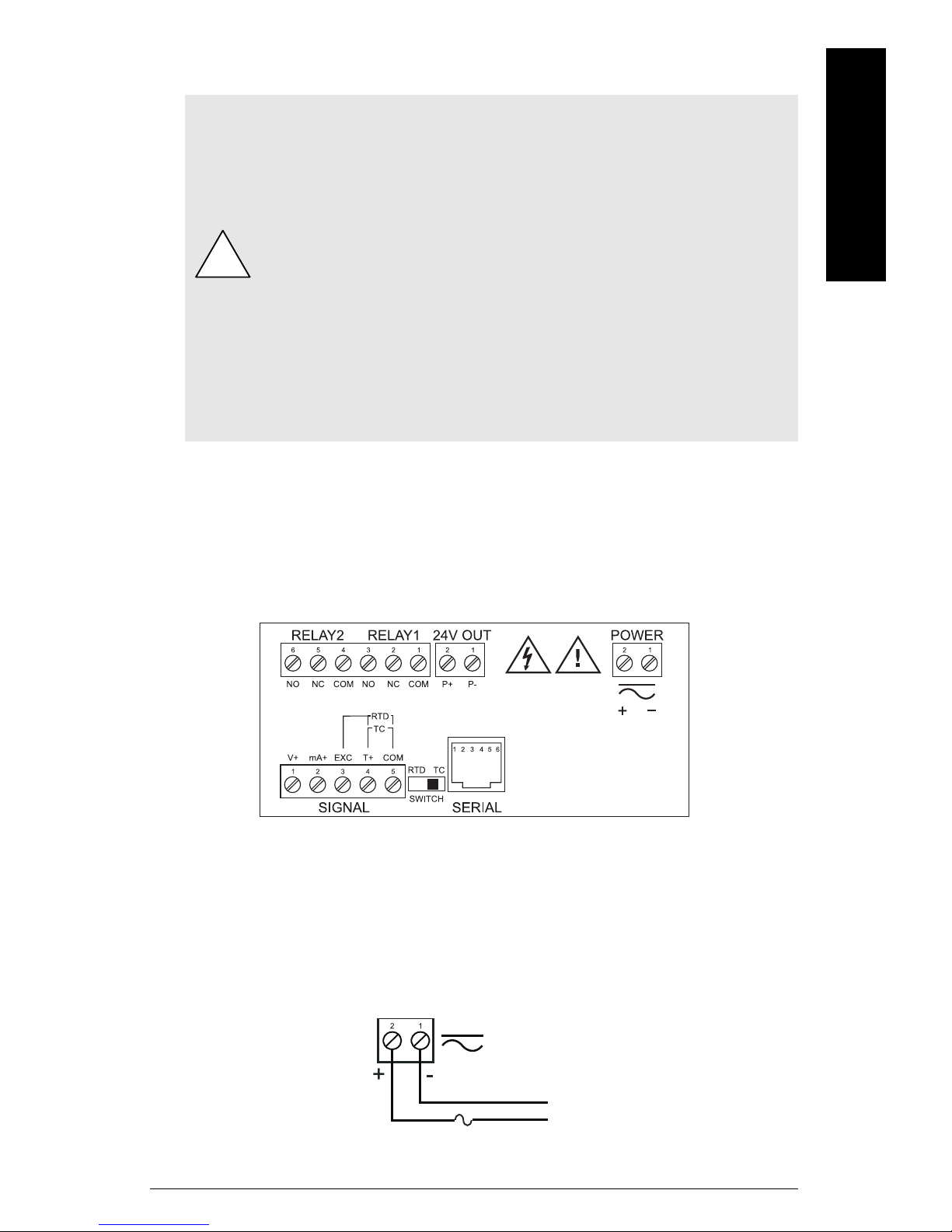
Connector Labeling
The connectors label, affixed to the meter, shows the location of all connectors available
with requested configuration. It also identifies the location of the RTD/TC selector switch.
Connections
mmmmm
Connector Labeling for Two Relays and 24 V Supply
Power Connections
Power connections are made to a two-terminal connector labeled POWER on diagram
Connector Labeling for Two Relays and 24 V Supply. The meter will operate regardless of
DC polarity connection. The + and - symbols are only a suggested wiring convention.
7ML19985JS01 SITRANS RD200 – OPERATING INSTRUCTIONS Page 11
mmmmm
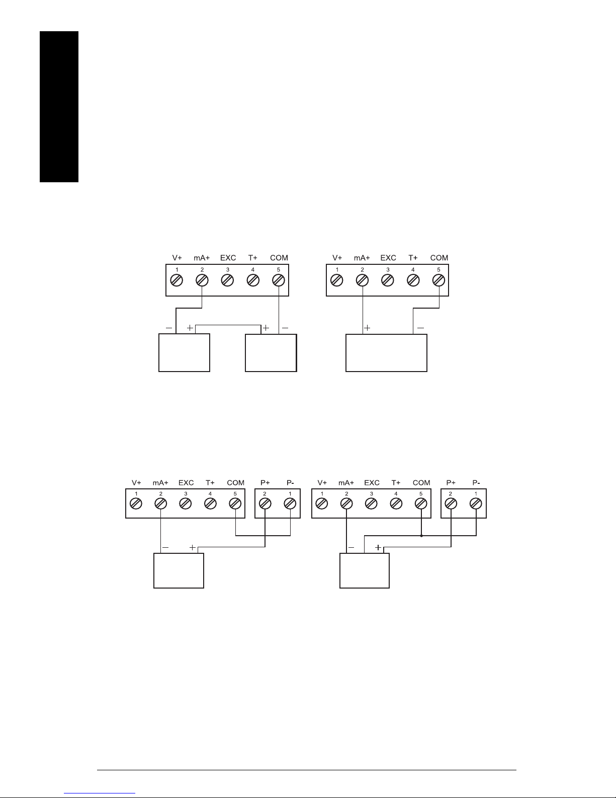
Transmitter powered by ext. supply or self-powered
signal connector
signal connector
2-wire
4 to 20 mA
transmitter
external
power
supply
2-wire 4 to 20 mA
self-powered
transmitter
2-wire
4 to 20 mA
transmitter
3-wire
4 to 20 mA
transmitter
signal connector
signal connector
24 V out
24 V out
signal
Transmitter powered by internal supply (optional)
Signal Connections
Signal connections are made to a five-terminal connector labeled
SIGNAL on diagram Connector Labeling for Two Relays and 24 V Supply. The COM
(common) terminal is the return for all types of input signals.
Current and Voltage Connections
Connections
The following figures show examples for current and voltage connections.
There are no switches or jumpers to set up for current and voltage inputs. Setup and
programming is performed through the front panel buttons.
The current input is protected against current overload by a fuse capable of being reset.
The display may or may not show a fault condition depending on the nature of the
overload.
The fuse limits the current to a safe level when it detects a fault condition, and
automatically resets itself when the fault condition is removed.
Page 12 SITRANS RD200 – OPERATING INSTRUCTIONS 7ML19985JS01
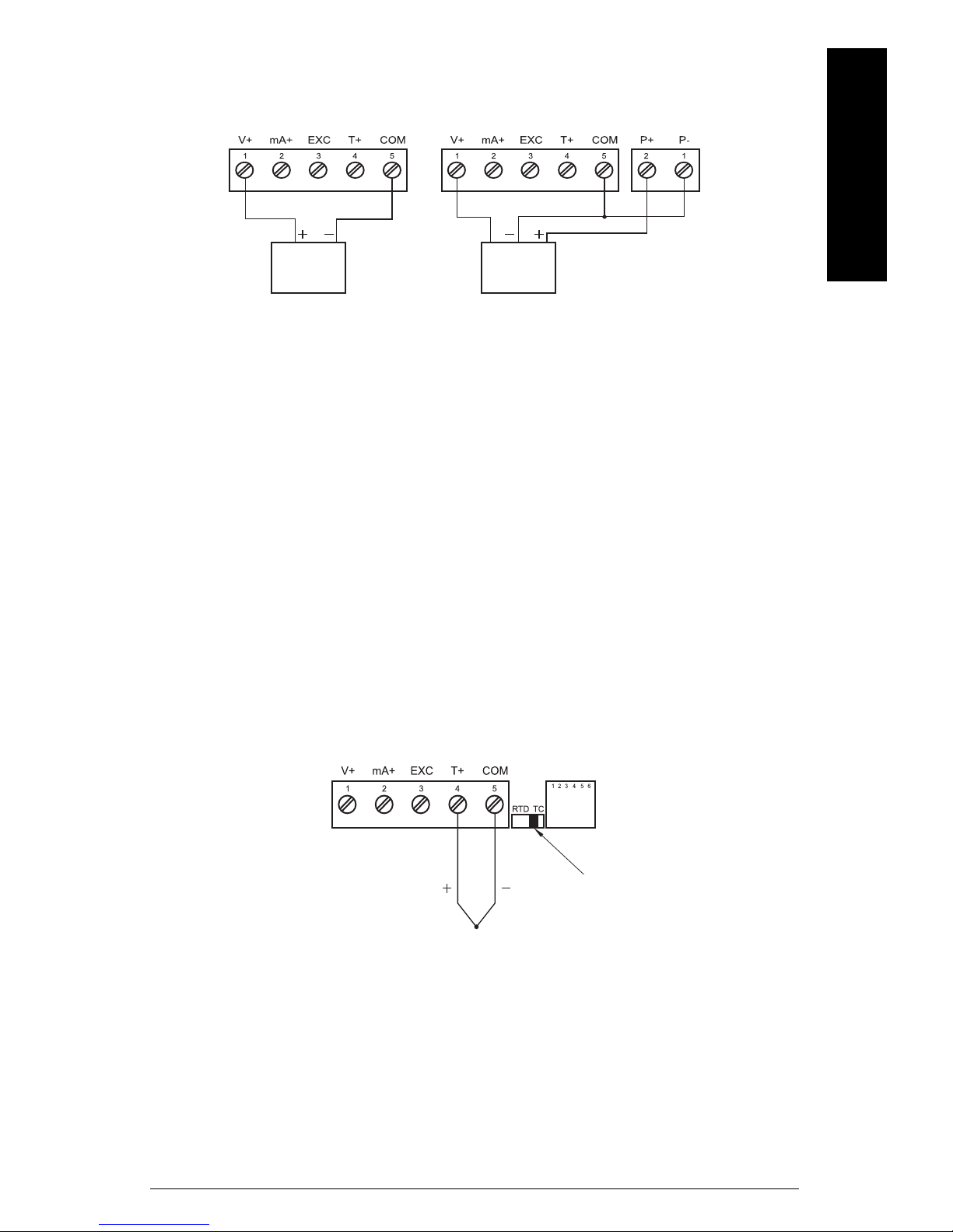
voltage
signal
3-wire
voltage
transducer
signal connector
signal connector
signal
24 V out
Thermocouple input connections
signal connector
TC
switch position
Voltage input connections
The meter is capable of accepting any voltage from -10 V DC to +10 V DC.
Thermocouple and RTD connections
The following figures show examples for thermocouple and RTD connections.
Connections
mmmmm
The RTD/TC selector switch must be set to the proper position for the meter to accept the
selected temperature input.
The input type is selected using the Setup (
Selected thermocouple input must correspond to thermocouple sensor and wire type
used.
SEtu
) menu.
7ML19985JS01 SITRANS RD200 – OPERATING INSTRUCTIONS Page 13
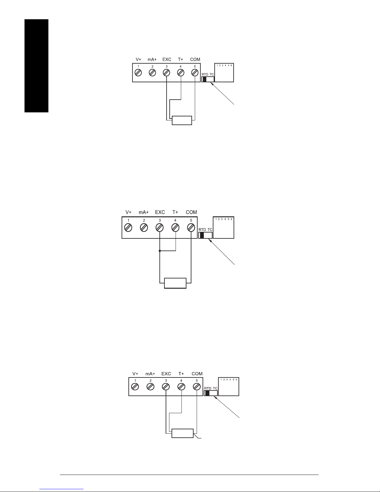
mmmmm
Three-wire RTD input connections
switch position
signal connector
RTD
sensor
Two-wire RTD input connections
signal connector
switch position
RTD
sensor
Four-wire RTD input connections
signal connector
switch position
RTD
sensor
NC
Connections
The meter accepts two, three, or four-wire RTDs. The three-wire RTD connection has
built-in lead wire compensation.
Lead wire compensation for two-wire RTDs can be applied using the Adjust (
Offset adjustment (Adj)
See
Page 14 SITRANS RD200 – OPERATING INSTRUCTIONS 7ML19985JS01
on page 42.
Adj
) menu.
The four-wire RTD connection is similar to the three-wire. One of the leads of a four-wire
RTD is not connected, and may be clipped off.
Connections
The three-wire connection provides sufficient lead wire compensation to provide
accurate readings even with long leads.
Serial Communication
Serial communication connection is made to an RJ11 connector labeled SERIAL on
Connector Labeling for Two Relays and 24 V Supply
Device to use For interfacing
RS232 serial adapter RS232
RS422/485 serial adapter RS422/485
SITRANS RD200 meter copy cable Meter-to-meter (for cloning purposes -
copying programmed settings from one
meter to other meters)
on page 11.
mmmmm
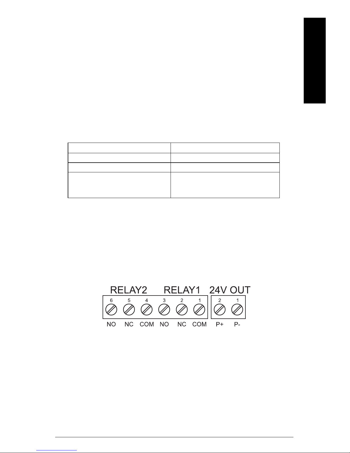
Relays and 24 V Output Connections
Relay connections are made to a six-terminal connector labeled
RELAY1, RELAY2 on
COM (common) terminals of the relays should not be confused with the COM (common)
terminal of the SIGNAL connector. The 24 V DC output is available at the connector
labeled 24V OUT, next to the relay connector.
Connector Labeling for Two Relays and 24 V Supply
on page 11. The
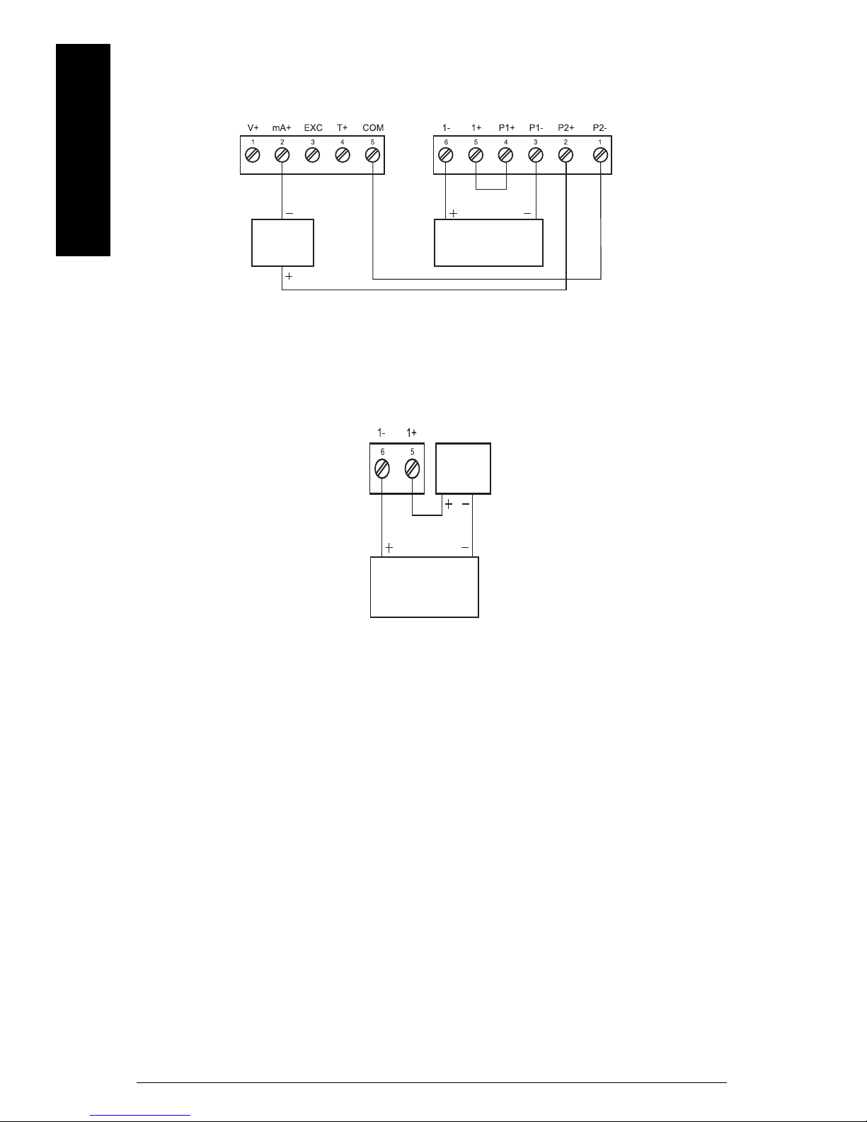
4 to 20 mA Output and Input Signal Connections
Connections for the 4 to 20 mA transmitter output are made to the connector terminals
labeled mA OUT, I-, I+. The 4 to 20 mA output may be powered from an internal power
supply (optional) or from an external power supply.
7ML19985JS01 SITRANS RD200 – OPERATING INSTRUCTIONS Page 15
mmmmm
4 to 20 mA Output and Input Signal Powered by Meter
signal connector
2-wire
4 to 20 mA
transmitter
remote display,
chart recorder
mA out
24 V out
4 to 20 mA Output Powered Externally
remote display,
chart recorder
mA out
external
power
supply
Connections
Page 16 SITRANS RD200 – OPERATING INSTRUCTIONS 7ML19985JS01
Setup
Notes:
• The meter is factory calibrated prior to shipment, for all input types, in
milliamps, volts, and degrees respectively.
• The calibration equipment is certified to NIST standards.
There are no jumpers involved in the setup of the meter. The RTD/TC selector switch,
located between the SIGNAL and SERIAL connectors, must be set accordingly for the
meter to accept RTD or thermocouple inputs. See Connector Labeling diagram on
page 11.
Setup and program the device using the front panel buttons.
After power and signal connections have been completed and verified, apply power to
the meter.
See
Appendix C - Quick User Interface Reference Guide
on page 59 for more
details.
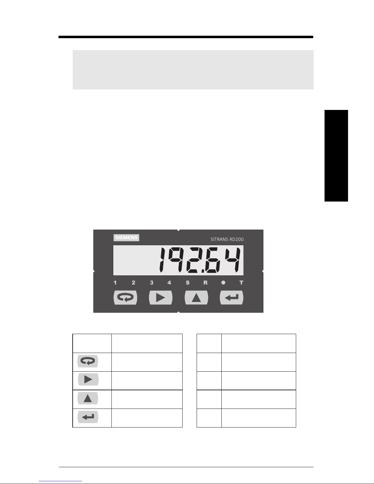
Front panel buttons and status LED indicators
Setup
mmmmm
Button
Symbol
Menu 1 Alarm 1
Right arrow/Reset 2 Alarm 2
Up arrow/Max S Set point indicator
Enter/Ack R Reset point indicator
7ML19985JS01 SITRANS RD200 – OPERATING INSTRUCTIONS Page 17
Description LED Status
Press Menu to enter or exit Program Mode at any time.
Press Right arrow to move to the next digit during programming.
Press Up arrow to scroll through the menus, decimal point, or to increment the
value of a digit.
Press Enter/Ack to access a menu or to accept a setting.
Press and hold Right arrow and Menu for three seconds to access
Advanced Features menu of the meter.
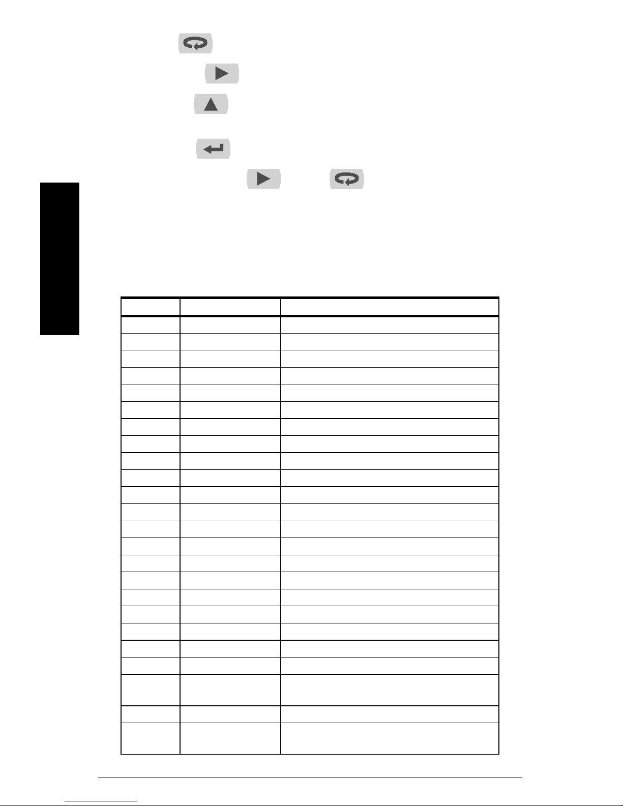
Display functions and messages
mmmmm
Setup
The following table shows the displayed functions and messages with their action/setting
description.
Display Parameter Action/Setting
SEtu Setup Enter Setup menu
inPt Input Enter Input menu
4-20 4-20 mA Set meter for 4 to 20 mA input
0-10 0-10 VDC Set meter for ±10 VDC input
rtd RTD Set meter for RTD input
A385 Alpha 385 Set α = 0.00385 European curve 100Ω RTD
A392 Alpha 392 Set α = 0.00392 American curve 100Ω RTD
tC TC Set meter for TC input
0 J 0 J Type J
1 k 1 K Type K
2 T 2 T Type T
3 t.0 3 T.0 Type T, 0.1° resolution
4 E 4 E Type E
F C °F or °C Set temperature scale
°F °F Set meter to Fahrenheit
°C °C Set meter to Celsius
dEc.P Decimal point Set decimal point for process inputs
rELy Relay Enter the Relay menu
rLY1 Relay1 Relay 1 setup
Act1 Action1 Set relay 1 action (automatic, latching, etc.)
Auto Automatic Set relay for automatic reset
A-m Auto-manual Set relay for automatic + manual reset any
time
LtCH Latching Set relay for latching operation
L-CL Latching-cleared Set relay for latching operation with manual
reset only after alarm condition has cleared
Page 18 SITRANS RD200 – OPERATING INSTRUCTIONS 7ML19985JS01

Altr Alternate Set relays for pump alternation control
oFF Off Disable relay and front panel status LEDs
Disable relay’s fail-safe operation
SEt1 Set1 Program set point 1
rSt1 Reset1 Program reset point 1
rLY2 Relay2 Setup relay 2
Act2 Action2 Set relay 2 action (automatic, latching, etc.)
SEt2 Set2 Program set point 2
rSt2 Reset2 Program reset point 2
FLSF Fail-safe Enter Fail-safe
menu
FLS1 Fail-safe1 Set relay 1 fail-safe operation
On On Enable fail-safe operation
FLS2 Fail-safe2 Set relay 2 fail-safe operation
dLAy Delay Enter Time delay
menu
dLy1 Delay1 Enter relay 1 time delay setup
On1 On1 Set relay 1 on time delay
OFF1 Off1 Set relay 1 off time delay
dLy2 Delay2 Enter relay 2 time delay setup
On2 On2 Set relay 2 on time delay
OFF2 Off2 Set relay 2 off time delay
Aout Analog Output Enter the Analog Output menu
SEbr Sensor break Program TC or RTD sensor break value for
analog out
out1 Output 1 Program output 1 value (e.g. 4 mA)
out2 Output 2 Program output 2 value (e.g. 20 mA)
ProG Program Enter the Program menu
ScAL Scale Enter the Scale menu
CAL Calibrate Enter the Calibrate menu
inP1 Input 1 Calibrate input 1 signal or program input 1
value
diS1 Display 1 Program display 1 value
inP2 Input 2 Calibrate input 2 signal or program input 2
value
diS2 Display 2 Program display 2 value
err Error Error, calibration not successful, check signal
PASS Password Enter the Password menu
unLC Unlocked Program password to lock meter
LoCd Locked Enter password to unlock meter
9999
-1999
open
Flashing display Overrange condition
Underrange condition
Open TC or RTD sensor
Setup
mmmmm
7ML19985JS01 SITRANS RD200 – OPERATING INSTRUCTIONS Page 19

Main menu
The main menu includes the most common functions: Setup, Program, and Password.
Press Menu to enter Program Mode then press Up arrow to scroll
through the main menu options; Setup (
Press Menu at any time to exit and return to Run Mode. Changes made to
settings prior to pressing Enter/Ack are not saved.
Changes to the settings are saved only after pressing Enter/Ack .
The display moves to the next menu every time a setting is accepted by
pressing Enter/Ack .
mmmmm
Setup
SEtu
), Program (
ProG
), and Password (
PAS S
).
Setting numeric values
The numeric values are set using the Right and Up arrow buttons.
When in programming mode and setting a numeric value, press Right arrow to
select next digit and Up arrow to increment digit value.
The digit being changed is displayed brighter than the rest.
Press Enter/Ack at any time to accept a setting or Menu to exit without
saving changes.
Setting up the meter (SEtu)
The Setup menu is used to select:
• Input signal the meter will accept
• Decimal point position for process inputs
•Units (°F or °C) for temperature inputs
• Relay operation
• 4 to 20 mA analog output setup
Page 20 SITRANS RD200 – OPERATING INSTRUCTIONS 7ML19985JS01
From Run mode, press Menu to access any menu or press Up arrow to
scroll through choices. Use Enter/Ack to accept any entry and press Menu
to exit at any time.
Notes:
• The relay menu is always available even if the relay option is not installed.
• Visual alarm indication is available through front panel LEDs and the
SITRANS RD Software.
• The Analog Output menu is available if selected in the Advanced Features
menu. 4 to 20 mA output option board is installed and setup at the factory.
Setting the input signal (inPt)
Setup
mmmmm
Enter the Input menu to set up the meter to display current (
thermocouple (
The voltage input is capable of accepting any signal from -10 to +10 V DC. Select voltage
input to accept 0-5, 1-5, 0-10, or ±10 V DC signals.
The current input is capable of accepting any signal from -20 to 20 mA. Select current
input to accept 0 to 20 or 4 to 20 mA signals.
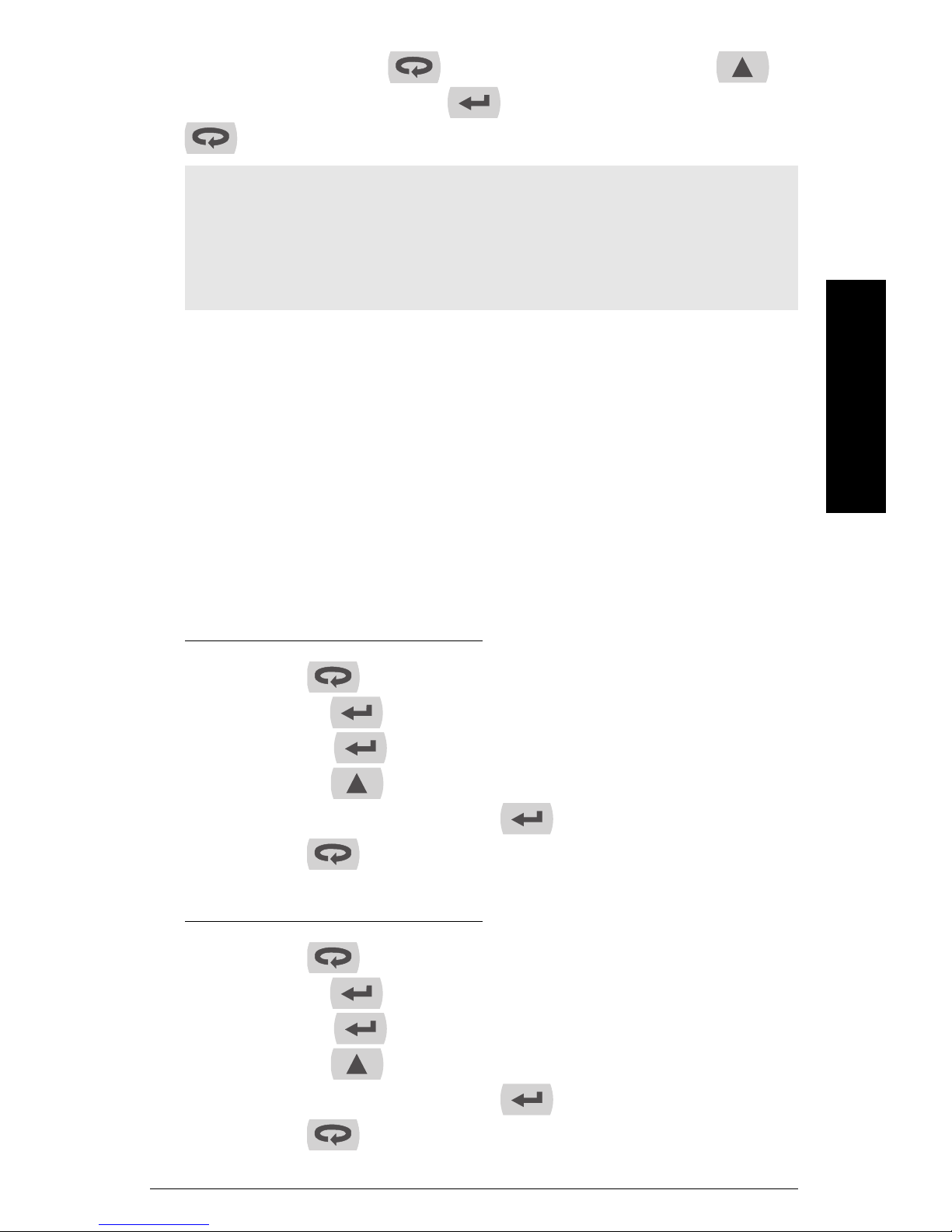
Setup meter to display current (
1. Press Menu to enter Programming Mode.
2. Press Enter/Ack to access Setup menu.
3. Press Enter/Ack to access Input menu.
4. Press Up arrow to scroll through choices;
5. When
6. Press Menu to return to Run Mode.
tC
), or RTD (
rtd
) inputs.
4-20
) input:
inPt
4-20
is displayed, press Enter/Ack to accept this choice.
4-20
), voltage (
SEtu
is displayed.
is displayed.
4-20, 0-10, tC, rtd
0-10
),
.
Setup meter to display voltage (
1. Press Menu to enter Program Mode.
2. Press Enter/Ack to access Setup menu.
3. Press Enter/Ack to access Input menu.
4. Press Up arrow to scroll through choices;
0-10
5. When
6. Press Menu to return to Run Mode.
7ML19985JS01 SITRANS RD200 – OPERATING INSTRUCTIONS Page 21
is displayed, press Enter/Ack to accept this choice.
0-10
) input:
4-20, 0-10, tC, rtd
.
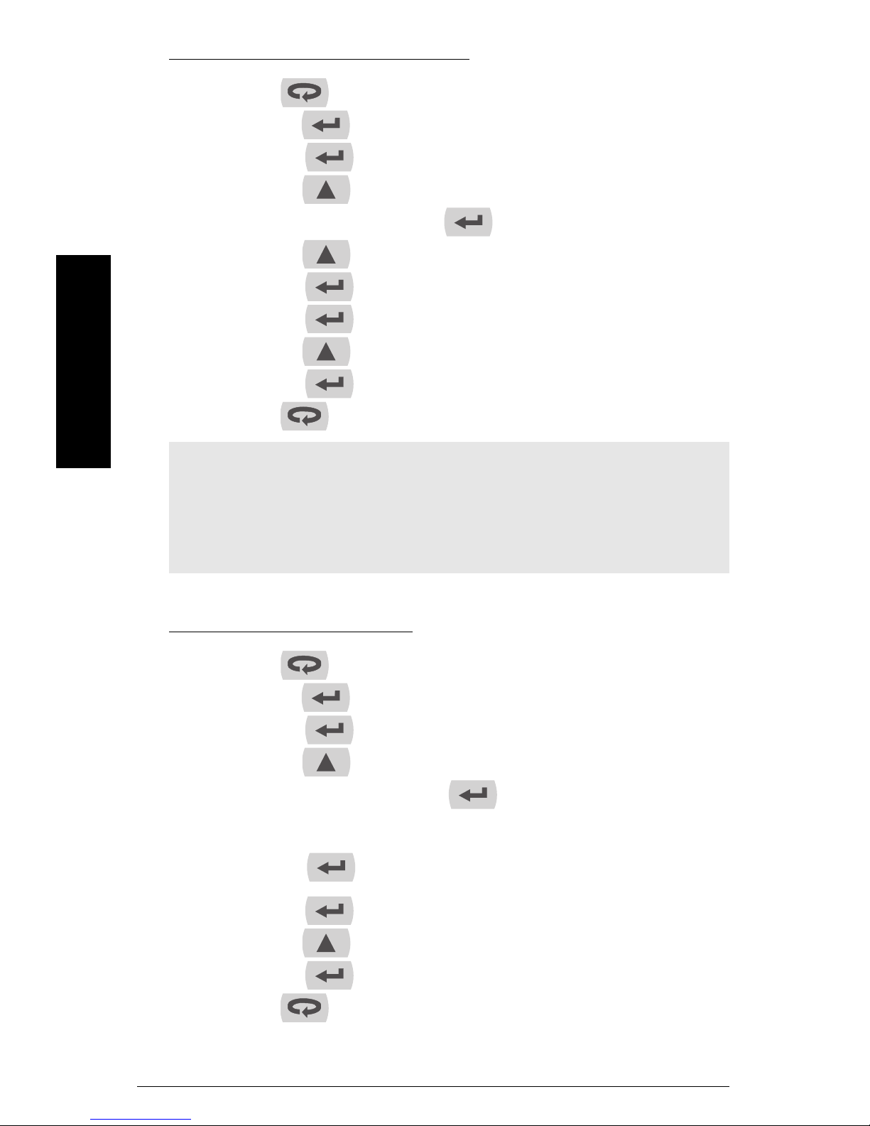
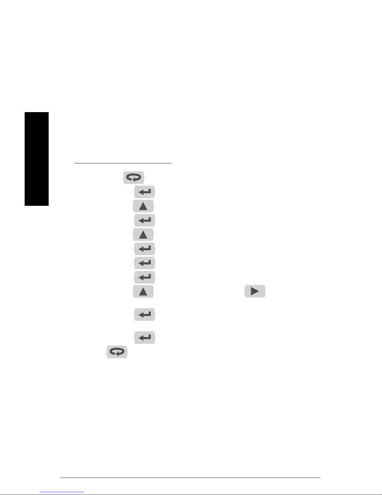
Setup meter to display thermocouple (
tC
) input:
1. Press Menu to enter Program Mode.
2. Press Enter/Ack to access Setup menu.
3. Press Enter/Ack to access Input menu.
4. Press Up arrow to scroll through choices;
5. When tC is displayed, press Enter/Ack .
6. Press Up arrow until
7. P r e ss Enter/Ack to accept choice.
8. Press Enter/Ack to set Fahrenheit or Celsius input.
9. Press Up arrow to scroll through choices.
mmmmm
Setup
10. Press Enter/Ack to accept a choice.
11. Press Menu to return to Run Mode.
1 H
is displayed.
SEtu
is displayed.
inPt i
4-20, 0-10, tC, rtd
F C
is displayed.
s displayed.
.
Notes:
•If tC is selected, the input signal must be connected to the appropriate input
terminals and the RTD/TC selector switch must be set accordingly, see
Thermocouple input connections
• For thermocouple inputs, allow at least 30 minutes warm-up time for meter
to reach specified accuracy.
on page 13.
rtd
Setup meter to display RTD (
1. Press Menu to enter Program Mode.
2. Press Enter/Ack to access Setup menu.
3. Press Enter/Ack to access Input menu.
4. Press Up arrow to scroll through choices;
5. When
6. The display shows A385 or A392. Select the coefficient to match the RTD sensor,
7. P r e ss Enter/Ack to set Fahrenheit or Celsius input.
8. Press Up arrow to scroll through choices.
9. Press Enter/Ack to accept a choice.
10. Press Menu to return to Run Mode.
rtd
is displayed, press Enter/Ack .
either 0.00385 (European curve) or 0.00392 (American curve).
Press Enter/Ack to accept your selection.
) input:
SEtu
is displayed.
inPt i
s displayed.
4-20, 0-10, tC, rtd
F C
is displayed.
.
Page 22 SITRANS RD200 – OPERATING INSTRUCTIONS 7ML19985JS01
.
Notes:
•If
• For thermocouple inputs, allow at least 30 minutes warm-up time for meter
rtd
is selected, the input signal must be connected to the appropriate input
terminals and the RTD/TC selector switch must be set accordingly, see
Thermocouple input connections
to reach specified accuracy.
on page 13.
Setting the decimal point (dEc.P)
Decimal point for temperature inputs is fixed.
Decimal point for process inputs may be set with up to three decimal places or with no
decimal point at all.
Pressing Up arrow moves the decimal point one place to the right until no
decimal point is displayed, then it moves to the leftmost position.
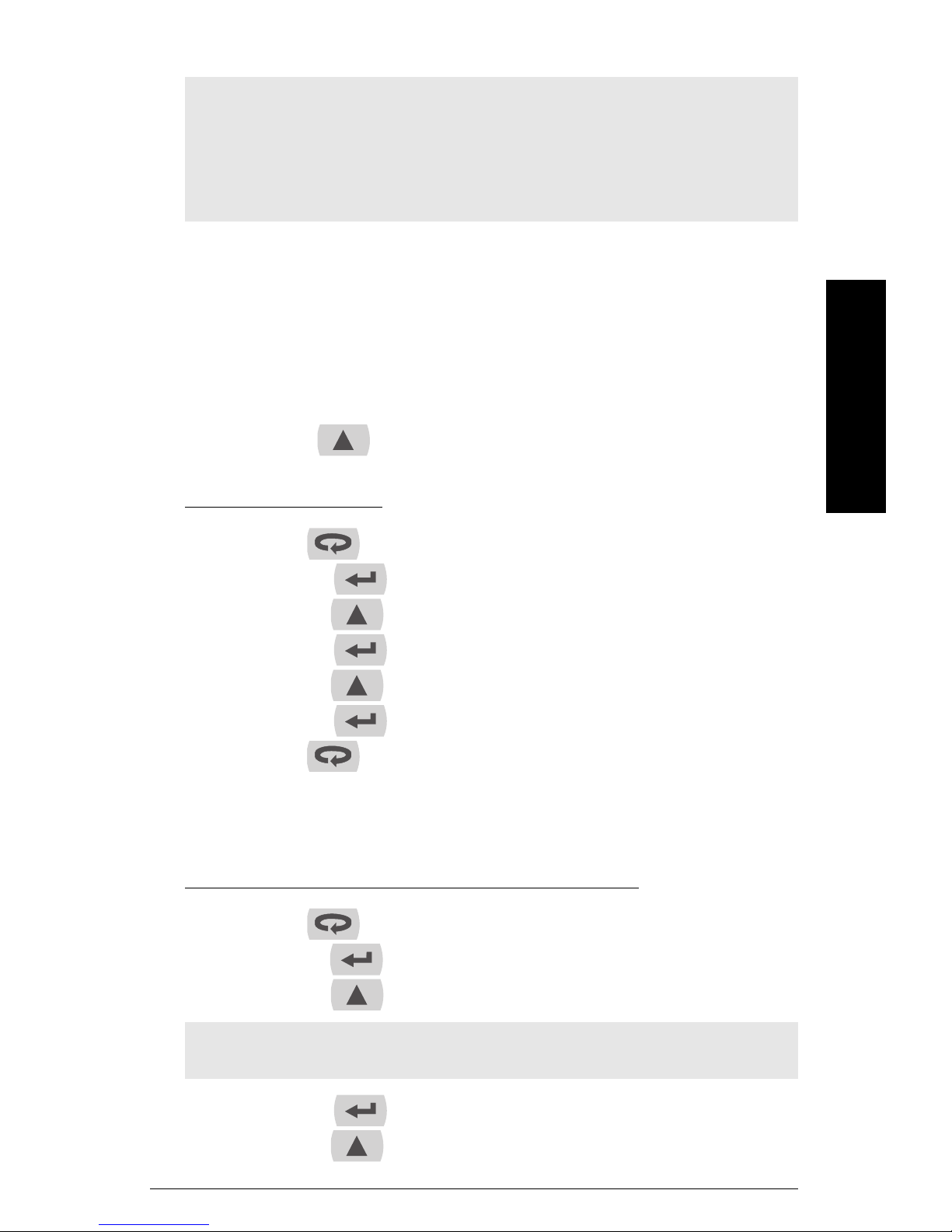
To change the decimal point:
1. Press Menu to enter Program Mode.
2. Press Enter/Ack to access the Setup menu.
3. Press Up arrow to select decimal point modification.
4. Press Enter/Ack to display decimal point setting.
5. Press Up arrow to move the decimal point from left to right.
6. Press Enter/Ack to accept the displayed setting.
7. P r e ss Menu to return to Run Mode.
SEtu
is displayed.
inPt i
s displayed.
dEc.P
is displayed.
Setup
mmmmm
Setting the temperature scale (F C)
Set meter to display temperature in degrees Fahrenheit or Celsius:
1. Press Menu to enter Program Mode.
2. Press Enter/Ack to access Setup menu.
3. Press Up arrow until temperature selection menu is displayed (
Note: The temperature selection menu will only be available if the meter has been
setup for TC or RTD input. See
4. Press Enter/Ack to access the temperature selection menu.
5. Press Up arrow to scroll through choices;
7ML19985JS01 SITRANS RD200 – OPERATING INSTRUCTIONS Page 23
SEtu
is displayed.
Setting the input signal (inPt)
F
or C.
on page 21.
F C
).

6. Press Enter/Ack to set Fahrenheit or Celsius input.
7. P r e ss Menu to return to Run Mode.
Setting relay operation (rELY)
This menu allows you to set up the operation of the relays:
• Relay action
• Automatic reset only (non-latching)
• Automatic + manual reset at any time (non-latching)
• Latching (manual reset only)
• Latching with Clear (manual reset only after alarm condition has cleared)
• Pump alternation control (automatic reset only)
mmmmm
Setup
• Off (relay and status LED disabled)
•Set point
• Reset point
• Fail-safe operation
• On (enabled)
• Off (disabled)
• Time delay
• On delay (0-199 seconds)
• Off delay (0-199 seconds)
Set Up Relays (rLY1, rLY2), Set points (SEt1, SEt2), and Reset points (rSt1, rSt2):
1. Press Menu to enter Program Mode.
2.
SEtu
is displayed. Press Enter/Ack to access the Setup menu.
rELy
3. Press Up arrow until
4. Press Enter/Ack to enter Relay menu.
5.
rLy1
is displayed. Press Enter/Ack to set up relay 1.
6.
Act1
is displayed. The relay Action menu allows the user to set up the action of the
relays.
Press Enter/Ack to set up action for relay 1.
7. P r e ss Up arrow to scroll through choices;
Auto
(Automatic reset only, non-latching),
A -m
(Automatic + manual reset at any time, non-latching),
LtCH
(Latching, manual reset only),
is displayed.
L -CL
(Latching with Clear, manual reset only after alarm condition has cleared),
ALtr
(Pump alternation control, automatic reset only),
oFF
(Off, relay and status LED disabled).
Page 24 SITRANS RD200 – OPERATING INSTRUCTIONS 7ML19985JS01
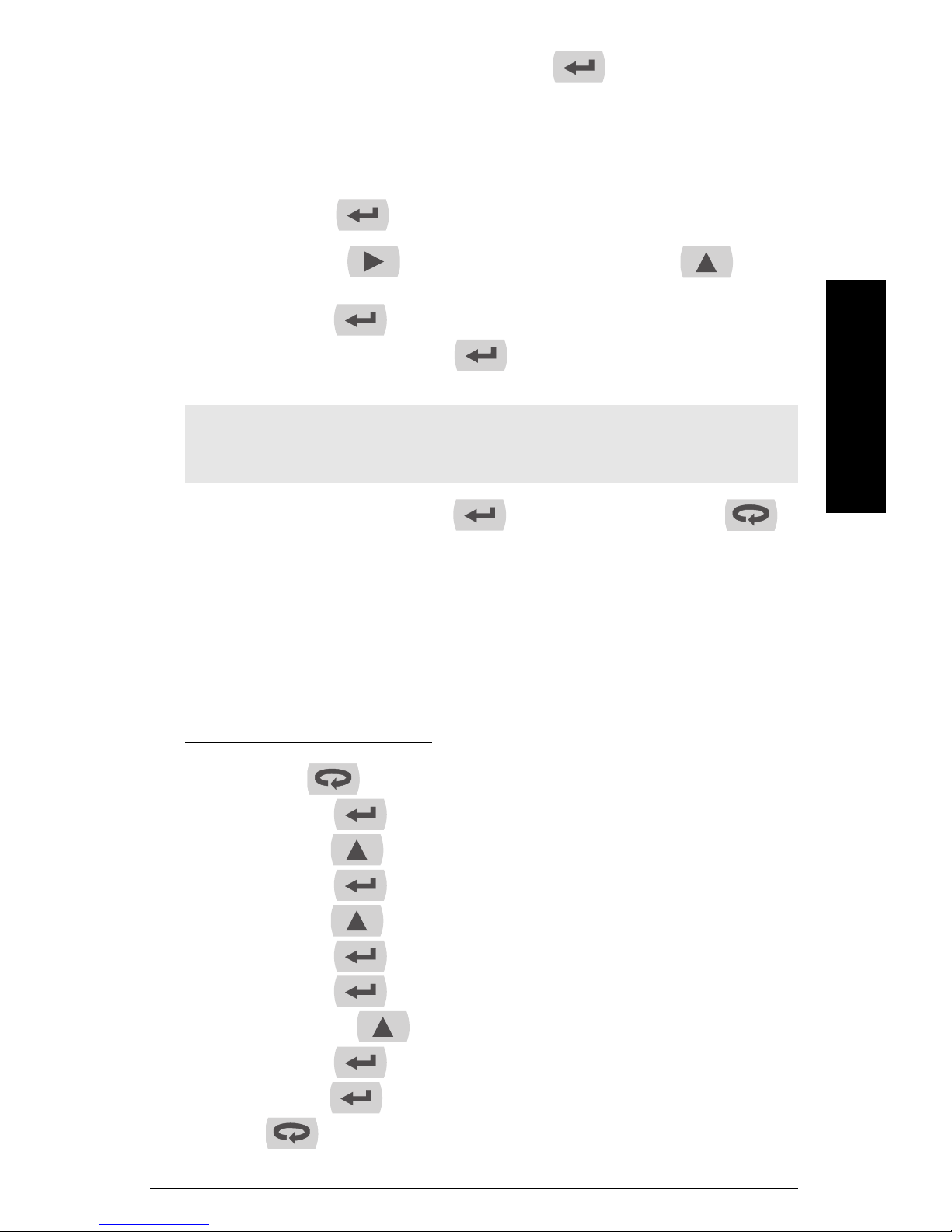
When your choice is displayed, press Enter/Ack to set relay 1 action (
SEt1
8.
9. Press Right arrow to change active digit and the Up arrow to
10. Press Enter/Ack to save displayed value.
11.
is displayed. The set point can be set to High Alarm Indication by programming
the set point above the reset point.
The set point can be set to Low Alarm Indication by programming the set point
below the reset point.
Press Enter/Ack to enter set point 1 programming.
increment active digit.
rSt1
is displayed. Press Enter/Ack to enter reset point 1 programming and
follow steps 8 and 9 above to program reset point 1 value.
Note: The deadband is determined by the difference between set and reset points.
Minimum deadband is one display count. If set and reset points are programmed the
same, relay will reset one count below set point.
12.
rLY2
is displayed. Press Enter/Ack to set up relay 2 or press Menu to
exit and return to Run Mode.
Act1
).
Setup
mmmmm
Setting fail-safe operation (FLSF: FLS1, FLS2)
The fail-safe operation is set independently for each relay. Select on to enable or select
off
to disable fail-safe operation.
Set up relays for fail-safe operation:
1. Press Menu to enter Program Mode.
2. Press Enter/Ack to access the Setup menu.
rELy
3. Press Up arrow until
4. Press Enter/Ack to enter Relay menu.
5. Press Up arrow until
6. Press Enter/Ack to access Fail-Safe Menu.
7. P r e ss Enter/Ack to set up fail-safe feature for relay 1.
8. Press the Up arrow to switch on or off.
is displayed.
FLSF
is displayed.
FLS1
is displayed.
9. Press Enter/Ack to accept settings.
10. Press Enter/Ack to set up fail-safe feature for relay 2 as in steps 7-9, or press
Menu to exit and return to Run Mode.
7ML19985JS01 SITRANS RD200 – OPERATING INSTRUCTIONS Page 25
FLS2
is displayed.
Once the Fail-Safe operation has been enabled, under normal conditions, the relays are
on, and under alarm conditions, the relays are off. (Notice that the functionality of the
relays is reversed when the Fail-Safe operation is disabled.)
Programming time delay (dLA: dLy1, dLy2)
The On and
seconds. The relays will transfer only after the condition has been maintained for the
corresponding time delay.
The
On
OFF
The
mmmmm
Setup
Set up relay on and off time delays:
1. Press Menu to enter Program Mode.
2. Press Enter/Ack to access the Setup menu.
3. Press Up arrow until
4. Press Enter/Ack to enter Relay menu.
5. Press Up arrow until
6. Press Enter/Ack to enter Time Delay Menu.
7. P r e ss Enter/Ack to set time delay for relay 1.
OFF
time delays may be programmed for each relay between 0 and 199
time delay is associated with the set point.
time delay is associated with the reset point.
rELy
is displayed.
dLAy
is displayed.
dLy1
is displayed.
On1
is displayed.
8. Press Enter/Ack to proceed.
9. Press Up arrow to change digit and Right arrow to change active
digit.
10. Press Enter/Ack to accept setting.
11. Repeat steps 6-7 for
12. Press Enter/Ack to set up time delay for relay 2 as in steps 8-10, or press
Menu to exit and return to Run Mode.
On
The
on after the time delay has elapsed. The
point is reached and the relay will turn off after the time delay has elapsed.
time delay will count down when the set point is reached and the relay will turn
OFF1. dLy2
is displayed.
OFF
time delay will count down when the reset
Page 26 SITRANS RD200 – OPERATING INSTRUCTIONS 7ML19985JS01
 Loading...