

Siemens sitrans PROBE LU Instruction Manual
Instruction Manual June 2004
sitrans
PROBE LU

Safety Guidelines
Warning notices must be observed to ensure personal safety as well as that of others, and to
protect the product and the connected equipment. These warning notices are accompanied
by a clarification of the level of caution to be observed.
Qualified Personnel
This device/system may only be set up and operated in conjunction with this manual.
Qualified personnel are only authorized to install and operate this equipment in accordance
with established safety practices and standards.
Warning: This product can only function properly and safely if it is correctly transported,
stored, installed, set up, operated, and maintained.
Note: Always use product in accordance with specifications.
Copyright Siemens Milltronics Process
Disclaimer of Liability
Instruments Inc. 2004. All Rights Reserved
This document is available in bound version and in
electronic version. We encourage users to
purchase authorized bound manuals, or to view
electronic versions as designed and authored by
Siemens Milltronics Process Instruments Inc.
Siemens Milltronics Process Instruments Inc. will
not be responsible for the contents of partial or
whole reproductions of either bound or electronic
versions.
MILLTRONICS®is a registered trademark of Siemens Milltronics Process Instruments Inc.
Contact SMPI Techni cal Publications at the following address:
Technical Publications
Siemens Milltronics Process Instruments Inc.
1954 Technology Drive, P.O. Box 4225
Peterborough, Ontario, Canada, K9J 7B1
Email: techpubs@siemens-milltronics.com
While we have verified the contents of
this manual for agreement with the
instrumentation described, variations
remain possible. Thus we cannot
guarantee full agreement. The
contents of this manual are regularly
reviewed and corrections are included
in subsequent editions. We welcome
all suggestions for improvement.
Technical data subject to change.
For the library of SMPI instruction manuals, visit our Web site: www.siemens-milltronics.com
© Siemens Milltronics Process Instruments Inc. 2004

Table of Contents
Safety Notes ...........................................................................................................................................1
Safety marking symbols ............................................................................................................1
The Manual ............................................................................................................................................1
Application Examples .................................................................................................................2
Abbreviations and Identifications ...........................................................................................2
SITRANS Probe LU ( Ul t r a sonic) ......................................................................................4
Applications ..................................................................................................................................4
Level, volume or flow ................................................................................................................. 4
SITRANS Probe LU System Implementation ........................................................................5
Programming ................................................................................................................................5
SITRANS Probe LU Approvals and Certificates ..................................................................5
Specification s ................. ..................... .................... .................... ................... ...................6
SITRANS Probe LU ............................................................................................................................... 6
Power............................................................................................................................................. 6
Performance................................................................................................................................. 6
Interface ........................................................................................................................................ 7
Programmer (infrared keypad) ................................................................................................ 7
Mechanical................................................................................................................................... 7
Environmental .............................................................................................................................. 8
Process.......................................................................................................................................... 8
Approvals (verify against device nameplate)....................................................................... 8
Installation . .......... .......... .......... ........ ........... .......... .......... ........ .......... ........... ........ ...............9
Mounting Instructions .......................................................................................................................10
SITRANS Probe LU Dimensions ............................................................................................11
Flange Adaptor (optional) ........................................................................................................11
Wiring ..... .................. ................ ................... .................. ................ ................... .................12
Power ...........................................................................................................................................12
Connecting the SITRANS Probe LU .....................................................................................12
Operating the SIT RANS Probe LU ................................................................................14
RUN Mode ............................................................................................................................................14
Display ......................................................................................................................................... 14
PROGRAM Mode ................................................................................................................................15
Programming ..............................................................................................................................15
Display ......................................................................................................................................... 15
Low temperature effects on RUN/PROGRAM modes ......................................................16
Security ........................................................................................................................................17
Starting PROGRAM mode .......................................................................................................17
Hand programmer .....................................................................................................................17
Activating SITRANS Probe LU .........................................................................................................17
Accessing a parameter ...........................................................................................................18
Changing a Parameter Value .................................................................................................18
Master Reset (P999) .................................................................................................................19
Using Units or Percent (%) .....................................................................................................19
Table of Contents
i

Setup Steps (outline) ..........................................................................................................................19
Setup Instructions .....................................................................................................................20
Additional Settings .............................................................................................................................25
Parameter Reference ....................................................................................................26
Helpful Hints ............................................................................................................................... 26
To access a parameter and change a value (primary index): ....................................... 26
To access a secondary index and change a value: ......................................................... 27
Table of Conttents
Quick Start (P001 to P010) ................................................................................................................. 28
Volume (or Flow) P050 to P055 ........................................................................................................ 31
Lock (P069)............................................................................................................................................ 39
Failsafe (P070 to P073) ....................................................................................................................... 39
mA Output (P201 to P215).................................................................................................................. 40
Installation Records (P300 to P346) ................................................................................................ 43
Range Calibration (P650 to P654) .................................................................................................... 45
Temperature Compensation (P660 to P664) ................................................................................. 48
Rate (P700 and P701).......................................................................................................................... 49
Measurement Verification (P709 to P713)..................................................................................... 50
P752 HART address ............................................................................................................................ 52
Communications (P799) ..................................................................................................................... 53
Echo Processing (P800 to P825) ...................................................................................................... 53
Algorithm (P820) .................................................................................................................................. 56
TVT (Time Varying Threshold) Adjustment Parameters (P830 to P839) ................................ 57
Diagnostic Tests (P900 to P924) ...................................................................................................... 60
Measurement ...................................................................................................................................... 61
Appendix A .......................................................................................................................65
Alphabetical Parameter List .............................................................................................................65
Appendix B .......................................................................................................................68
Programming Chart ............................................................................................................................68
Appendix C .......................................................................................................................71
HART Communications for the SITRANS Probe LU ...................................................................71
HART Device Description (DD) ..............................................................................................71
SIMATIC Process Device Manager (PDM): .......................................................................71
HART Communicator 275: .......................................................................................................72
Supported HART Commands:................................................................................................. 77
Burst mode ................................................................................................................................. 77
Appendix D: Troubleshooting .......................................................................................78
Communication Troubleshooting ....................................................................................................78
Generally: ....................................................................................................................................78
Specifically: .................................................................................................................................78
General Fault Codes ...........................................................................................................................79
Operation Troubleshooting ...............................................................................................................81
Maintenance . ...................... ....................... ...................... .................... ....................... .....81
Unit Repair and Excluded Liability ..................................................................................................81
ii

Appendix E: Technical References ..............................................................................82
Principles of operation ......................................................................................................................82
Blanking Distance ...............................................................................................................................82
TVT (Time Varying Threshold) curves ............................................................................................82
Auto False-Echo Suppression ................................................................................................83
Open Channel Monitoring (OCM) ...................................................................................................84
Failsafe ..................................................................................................................................................85
Chemical compatibility .......................................................................................................................85
Appendix F: Hazardous area installations ..................................................................86
Wiring Details ......................................................................................................................................86
Intrinsically Safe Model ...........................................................................................................86
FM/CSA ........................................................................................................................................87
EU Equivalency .......................................................................................................................... 87
Loop Voltage versus Loop Resistance .................................................................................88
IS Safety Barrier Selection .....................................................................................................88
How to select a passive barrier for SITRANS Probe LU ................................................. 88
PLC Input Modules.................................................................................................................... 89
Passive Shunt Diode Barriers ............................................................................................... 89
Active barriers (repeating barriers) ...................................................................................... 89
Product Nameplate ............................................................................................................................90
....................................................................................................................................................... 90
Intrinsically safe connection drawing (FM) ..................................................................................91
Intrinsically safe connection drawing (CSA) ................................................................................92
Instructions specific to hazardous area installations ................................................................93
(Reference European ATEX Directive 94/9/EC, ..................................................................93
Annex II, 1/0/6) ...........................................................................................................................93
Glossary ............................................................................................................................95
Index ....... .................... .................... ................... .................... ..................... .......................99
Table of Contents
iii

Table of Conttents
iv
Safety Notes
Special attention must be paid to warnings and notes highlighted from the rest of the text
by grey boxes.
1
WARNING: relates to a caution symbol on the product, and means
that failure to observe t he necessary precautions can r esult in death,
serious injury, and/or considerable material damage.
WARNING
1
: means that failure to observe the necessary
precautions can result in death, serious injury, and/or considerable
material damage
CAUTION: means that f ai lure to observe the necessary precautions can
result in considerabl e ma terial damage
Note:
means important information about the product or that part of the operating
manual.
Safety marking symbols
In manual: On product: Description
(Label on product: yellow background.) Caution: refer to
accompanying documents (manual) for details.
The Manual
SITRANS Probe LU
Notes:
• Please follow the installation and operating procedures for a quick, trouble-free
installation and to ensure the maximum accuracy and reliability of your
SITRANS Probe LU.
• This manual applies to the SITRANS Probe LU only.
This manual will help you set up your SITRANS Probe LU for optimum performance. We
always welcome suggestions and comments about manual content, design, and
accessibility.
Please direct your comments to techpubs@siemens-milltronics.com
library of Siemens Milltronics manuals, go to www. siemens-milltronics.com
1.
This warning symbol is used when there is no corresponding caution symbol on the
product.
7ML19985HT01 SITRANS Probe LU – INSTRUCTION MANUAL Page 1
. For the complete
.

Application Examples
The application examples used in this manual illustrate typical installations using
SITRANS Probe LU. Because there is often a range of ways to approach an application,
other configurations may also apply.
In all examples, substitute your own application details. If the examples do not apply to
your application, check the applicable parameter reference for the available options.
If you require more information, please contact your Siemens Milltronics representative. For a
complete list of Siemens Milltronics representatives, go to www.siemens-milltronics.com.
Abbreviations and Ident i fications
SITRANS Prob e LU
Short
form
CE / FM /
CSA
C
i
D/A Digital to analog
ETFE Ethylene-tetrafluoroethylene
HART
I
i
I
o
IS Intrinsically Safe safety approval
L
i
LRV Lower Range Value value for process empty level 4 mA
LSL Lower Sensor Limit
µs microsecond 10
PBT Polybutylene Terephthalate
PED
PVDF polyvinylidene fluoride
Long Form Description Units
Conformitè Europèene /
Factory Mutual / Canadian
Standards Association
Internal capacitance
Highway Addressable
Remote Transducer
Input current mA
Output current mA
Internal inductance mH
Pressure Equipment
Directive
safety approval
below which no PV is
anticipated
-6
safety approval
Second
1
Page 2 SITRANS Probe LU – INSTRUCTION MANUAL 7ML19985HT01

Short
form
Long Form Description Units
ppm parts per million
PV Primary Variable measured value
SELV Safety extra low voltage
SV Secondary Variable equivalent value
TVT Time Varying Threshold sensitivity threshold
U
i
U
o
Input voltage V
Output voltage V
URV Upper Range Value value for process full level 20 mA
USL Upper Sensor Limit
1.
100% is most commonly set to 20 mA, and 0% to 4 mA: however, the settings
above which no PV is
anticipated
can be reversed.
1
SITRANS Probe LU
7ML19985HT01 SITRANS Probe LU – INSTRUCTION MANUAL Page 3
SITRANS Probe LU (Ultrasonic)
WARNING: Changes or modifications not expressly approved by
Siemens Milltronics could void the user’s authority to operate the
equipment.
Note:
SITRANS Probe LU is to be used only in the manner outlined in this manual,
otherwise protection provided by the equipment may be impaired.
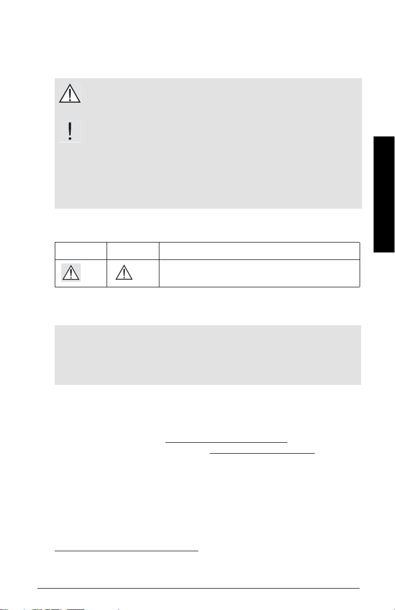
SITRANS Probe LU is a loop-powered continuous level monitor, using advanced
ultrasonic techniques. The unit consists of an electronic component coupled to the
transducer and process connection.
The transducer is available in ETFE (ethylene-tetrafluoroethylene) or PVDF
(polyvinylidene fluoride), allowing SITRANS Probe LU to be used in a wide variety of
industries and applications using corrosive chemicals.
SITRANS Prob e LU
The ultrasonic transducer contains a temperature sensing element to compensate for
temperature changes in the application.
Applications
Level, volume or flow
SITRANS Probe LU is designed to measure levels of liquids in a variety of applications:
• storage type vessels
• simple process vessels with some surface agitation
•liquids
• slurries
• open channels
Page 4 SITRANS Probe LU – INSTRUCTION MANUAL 7ML19985HT01
Volume
By using the volume parameters (P050 to P055) you can obtain the measurement as
volume instead of level.
Flow
If you have an open channel system (a Parshall flume, v-notch weir or other open channel
device), you can obtain flow values instead of level. By using the universal linear function
of parameter P051, and entering values for Head and Flow in the breakpoint parameters
P054 and 055, you can use SITRANS Probe LU to convert head levels into flow rates.
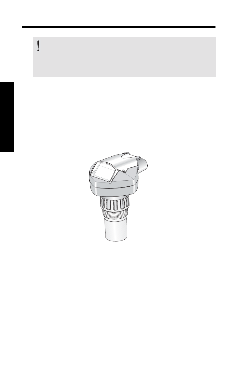
SITRANS Probe LU System Implementation
SITRANS Probe LU supports the HART communications protocol and SIMATIC PDM
software.
Typical PLC/mA configuration with HART
hand programmer
1 2
power supply
SITRANS
Probe LU
active PLC
1
2
R
= 250 Ω
HART modem
HART
communicator
Programming
SITRANS Probe LU carries out its level measurement function according to the set of
built-in parameters. Parameter changes can be made via the hand programmer, via a PC
using SIMATIC PDM, or via a HART Handheld Communicator.
SITRANS Probe LU
SITRANS Probe LU Approvals and Certificates
Note: Please see
1.
Depending on the system design, the power supply may be separate from the PLC, or
integral to it.
2.
A 250 Ohm resistor may be required if the loop resistance is less than 250 Ohms.
7ML19985HT01 SITRANS Probe LU – INSTRUCTION MANUAL Page 5
Approvals
on page 8 for an approvals listing.

Specifications
Note:
• Siemens Milltronics makes every attempt to ensure the accuracy of these
specifications but reserves the right to change them at any time.
• Please check the ambient and operating temperatures under
Process
8, and
page 8, for the specific configuration you are about to use or install.
on page 8; also check
SITRANS Probe LU
Power
Approvals (verify against device nameplate)
Environmental
on page
on
Performance
Specifications
Nominal 24 V DC at
max. 550 Ohm.
• Maximum 30 V DC
• 4 to 20 mA
For other configurations, see the chart
versus Loop Resistance
on page 88.
Loop Voltage
1
• frequency 54 KHz
• measurement range
12 m (40 ft) model: 0.25 m to 12 m (10" to 40 ft) liquid
• blanking distance
• accuracy
• repeatability ≤ 3 mm (0.12")
• resolution ≤ 3 mm (0.12")
• update time at 4mA ≤ 5 s
•beam angle 10
• temperature compensation built in to compensate over temperature range
• memory non-volatile EEPROM,
no battery required
3
2
2
6 m (20 ft) model: 0.25 m to 6 m (10" to 20 ft) liquid
0.25 m (0.82 ft)
the greater of 6 mm (0.25") or 0.15% of span (including
hysteresis and repeatability)
o
at –3 dB boundary
1.
Reference conditions.
2.
Reference point for measurement is the transducer face.
3.
Measured according to terminal based non-linearity method of IEC 60770-1.
Page 6 SITRANS Probe LU – INSTRUCTION MANUAL 7ML19985HT01

Interface
• HART standard, integral to analog output
• configuration Siemens SIMATIC PDM (PC), or HART handheld
communicator, or Siemens Milltronics infrared hand
programmer
• analog output 4–20 mA
• display (local) multi-segment alphanumeric liquid crystal with Bar
graph (representing level)
± 0.02 mA accuracy
Programmer (in frared keypad)
Siemens Milltronics Infrared IS (Intrinsically Safe) Hand Programmer: for all locations,
including hazardous.
• approval ATEX II 1 G, EEx ia IIC T4, SIRA 01ATEX2147
• ambient temperature −20 to 40° C (−5 to 104° F)
• interface proprietary infrared pulse signal
• power 3V lithium battery (non-replaceable)
• weight 150 g (0.3 lb)
• color black
Mechanical
Process Connections
• threaded connection 2” NPT, BSP, or G/PF
• flange connections 3" (80 mm) universal flange
• other connections FMS 200 mounting bracket, or customer-supplied
mount
Transducer (2 options)
• ETFE (ethylene-tetrafluoroethylene), or
• PVDF (polyvinylidene fluoride)
Enclosure
• body construction PBT (polybutylene terephthalate)
• lid construction hard-coated PEI (polyether imide)
• conduit entry 2 x M20 cable gland, or 2 x 1/2" NPT thread
• ingress protection Type 4X / NEMA 4X, Type 6 / NEMA 6, IP67 (see note
below)
Notes:
• Please check the ambient and operating temperatures under
8, and
Process
on page 8; also check
page 8, for the specific configuration you are about to use or install.
• The use of approved watertight conduit hubs/glands is required for Type 4X /
NEMA 4X, Type 6 / NEMA 6, IP67 (outdoor application).
Approvals (verify against device nameplate)
Environmental
Specifications
on page
on
7ML19985HT01 SITRANS Probe LU – INSTRUCTION MANUAL Page 7

Weight
Standard model 2.1 kg (4.6 lb.)
Environmental
• location indoor/outdoor
• altitude 2000 m (6,562 ft) max.
• ambient temperature −40 to 80° C (−40 to 176° F)
• relative humidity suitable for outdoor
(Type 4X / NEMA 4X, Type 6 / NEMA 6, IP67 enclosure)
• installation category I
• pollution degree 4
• pressure rating ambient
Process
•temperature
(at flange or threads) −40 to 85° C (−40 to 185° F)
• pressure (vessel) ambient, vented to atmosphere
Approvals (verify against device nameplate)
• General CSA
• Hazardous Europe: ATEX II 1 G, EEx ia IIC T4
US: Intrinsically Safe
Class I, Div. 1, Groups A, B, C, D (barrier required)
Class II, Div. 1, Groups E, F, G
Specifications
Class III
Canada: Intrinsically Safe
Class I, Div. 1, Groups A, B, C, D (barrier required)
Class II, Div. 1, Groups E, F, G
Class III
US/C
, FM, CE
Notes:
• Please check the ambient and operating temperatures under
Process
(above), as well as
use or install.
• The use of approved watertight conduit hubs/glands is required for Type 4X /
NEMA 4X, Type 6 / NEMA 6, IP67 (outdoor application).
Page 8 SITRANS Probe LU – INSTRUCTION MANUAL 7ML19985HT01
Approvals
, for the specific configuration you are about to
Environmental
, and
Installation
WARNING: This product can only function properly and safely if it is
correctly transpo r te d, stor ed, installed, set up, oper ated an d
maintained.
Notes:
• Installation shall only be performed by qualified personnel and in accordance with
local governing regulations.
• This product is susceptible to electrostatic shock. Follow proper grounding
procedures.
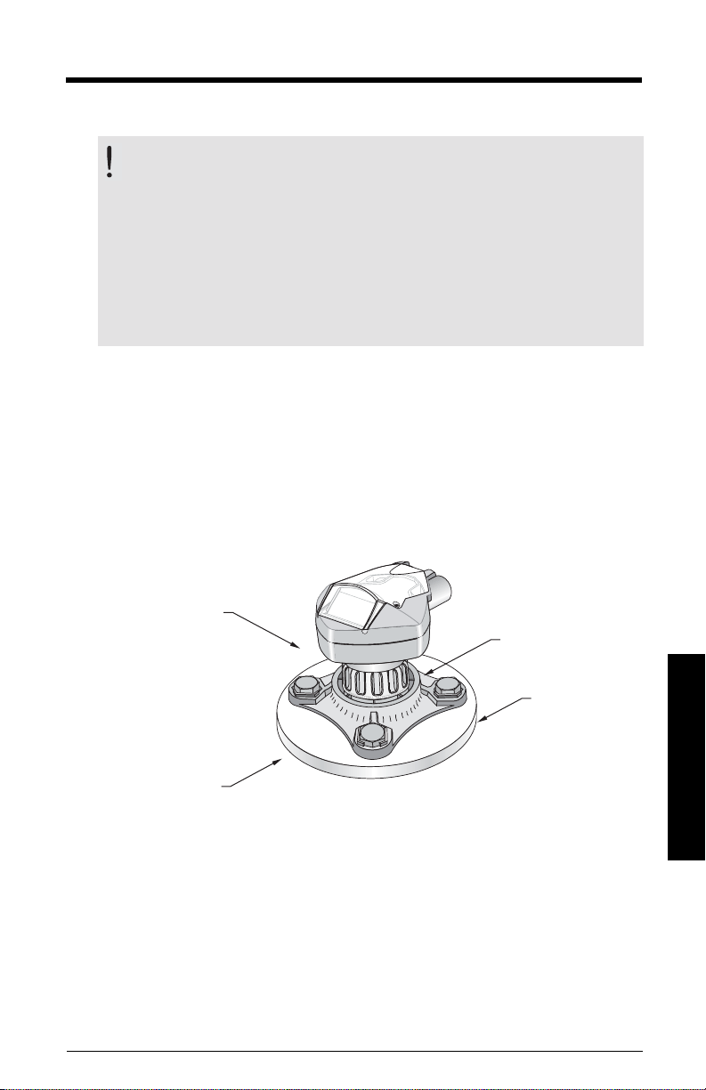
• Ideally, mount SITRANS Probe LU so that the face of the transducer is at least 30 0
mm (1 ft) above the highest anticipated level.
Mounting Location
Recommendations:
• Ambient temperature within –40 to 80 oC (–40 to 176 oF).
• Easy access for viewing the display and programming via the hand programmer.
• An environment suitable to the housing rating and materials of construction.
• Keep the sound path perpendicular to the material surface.
.
ambient temperature
surrounding enclosure
o
–40 to 80
process temperature
–40 to 85
C (–40 to 176 oF)
o
C (–40 to 185oF)
flange adaptor (option)
customer-supplied
flange
7ML19985HT01 SITRANS Probe LU – INSTRUCTION MANUAL Page 9
Installation

Precautions:
• Avoid proximity to high voltage or current wiring, high voltage or current contacts,
and to variable frequency motor speed controllers.
• Avoid interference to the sound path from obstructions or from the fill path
Fill
The sound path should be:
• perpendicular to the
monitored surface
• clear of rough walls,
seams, rungs, or
other obstructions.
• clear of the fill path
pipe
rungs
seams
Mounting Instructions
Note:
• Ideally, mount SITRANS Probe LU so that the face of the transducer is at least 300
mm (1 ft) above the highest anticipated level.
SITRANS Probe LU is available in three thread types: 2" NPT, 2" BSP, or PF2/G.
1. Before inserting SITRANS Probe LU into its mounting connection, ensure that the
threads are of the same type to avoid damaging them.
2. Simply screw SITRANS Probe LU into the process connection and hand tighten.
10°
Installation
Page 10 SITRANS Probe LU – INSTRUCTION MANUAL 7ML19985HT01
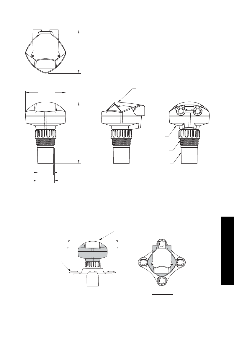
SITRANS Probe LU Dimensions
.
139.7 mm
(5.50")
130.1 mm
(5.12")
198.9 mm
(7.83")
51.1 mm (2.01")
54.0 mm (2.13")
hinged lid
electronics
mounting
thread
transducer
Flange Adaptor (optional)
SITRANS Probe LU can be fitted with the optional 3" (80 mm) flange adaptor for mating to
3" ANSI, DIN 65PN10 and JIS 10K3B flanges.
SITRANS Probe LU
"A" "A"
Installation
Optional flange
adaptor
VIEW "A"-"A"
7ML19985HT01 SITRANS Probe LU – INSTRUCTION MANUAL Page 11
Wiring
Power
1
WARNINGS:
DC terminals shall be supplied from an SELV
1
source in
accordance with IEC-1010-1 Annex H.
All field wiring must have insulation suitable for rated voltages.
Connecting the SITRANS Probe LU
Notes:
• Use shielded, twisted pair cable (wire gauge AWG 22 to AWG 14/ 0.34 mm2 to
• Separate cables and conduits may be required to conform to standard
• The non-metallic enclosure does not provide a continuous ground path between
• For detailed information on Intrinsically Safe setups, see page 86.
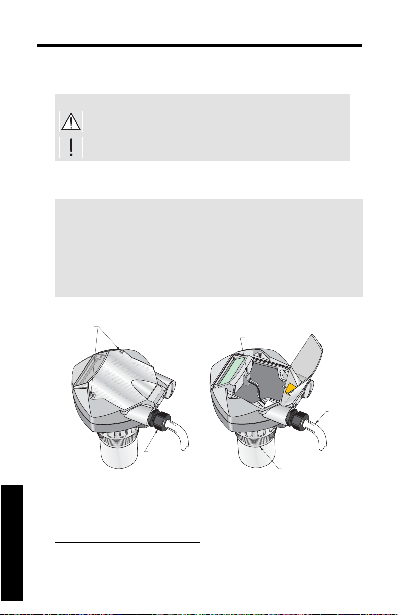
cover screws
2
2.08 mm
).
instrumentation wiring practices, or electrical codes.
conduit connections: use grounding-type bushings and jumpers.
terminals for loop
current
mmmmm
watertight
Wirng
gland
1. Strip the cable jacket for approximately 70 mm (2.75") from the end of the cable, and
thread the wires through the gland
1.
Safety Extra Low Voltage
2.
If cable is routed through conduit, use only approved suitable-size hubs for
2
.
threaded
connection
waterproof applications.
Page 12 SITRANS Probe LU – INSTRUCTION MANUAL 7ML19985HT01
cable
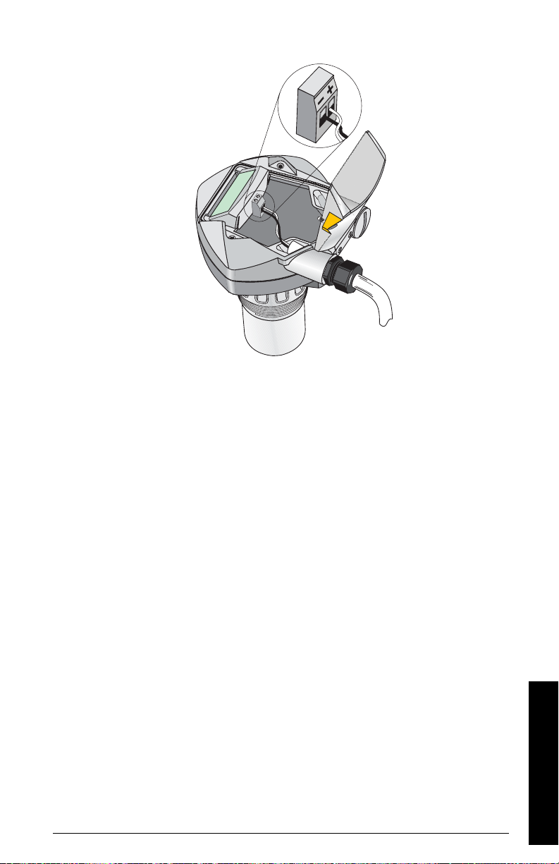
2. Connect the wires to the terminals as shown below: the polarity is identified on the
terminal block.
3. Tighten the gland to form a good seal.
4. Close the cover and tighten screws: please do not overtighten screws.
Recommended torque is 1.1 to 1.7 N-m (10 to 15 in-lb).
7ML19985HT01 SITRANS Probe LU – INSTRUCTION MANUAL Page 13
Wiring
mmmmm
Operating the SITRANS Probe LU
SITRANS Probe LU has two modes of operation: RUN and PROGRAM.
RUN Mode
Operation
SITRANS Probe LU automatically starts in RUN mode when power is applied, and detects
the material level. The primary reading displays the material level (in meters) referenced
from Empty (process empty level). This is the default start-up display mode.
System status is displayed on the LCD, or on a remote communications terminal.
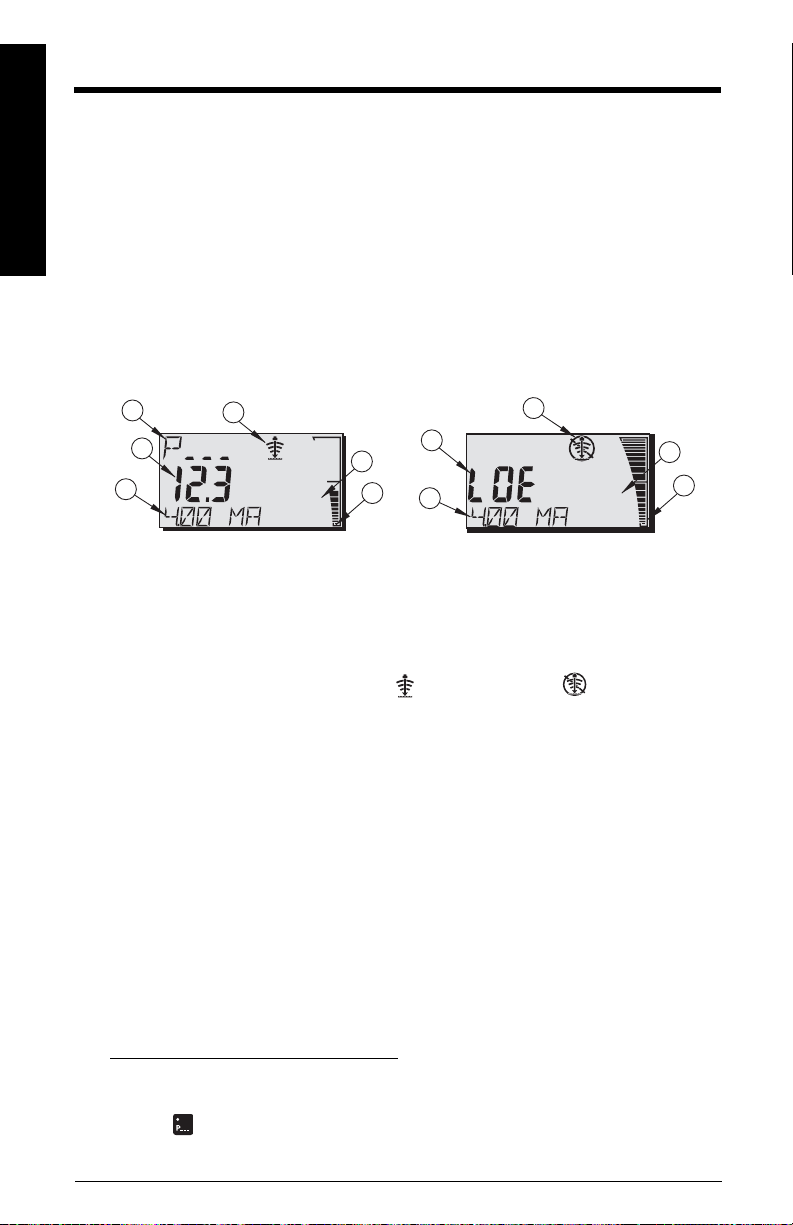
Display
Normal operation Fail-safe operation
2
1
6
1 – Primary Reading (displays level, distance, or volume (or flow1), in either units or
percent)
2 – Secondary Reading (displays Parameter number for Auxiliary Reading
3
1
4
5
m
6
3
4
m
2
)
5
3 – Echo status indicator: Reliable Echo or Unreliable Echo
4 – Units or Percent
5 – Active bar graph represents material level
6 – Auxiliary Reading (depending on the parameter selected, it displays milliAmp value,
distance or confidence, with units where applicable)
If the echo confidence drops below the echo confidence threshold
3
, the failsafe timer
starts running. When the timer expires, the letters LOE alternate with the reading every
two seconds, and the Reliable Echo indicator is replaced by the Unreliable Echo indicator.
When a valid reading is received, the level reading display returns to normal operation.
1.
See
P050 Vessel (or Channel) Shape
volume.
2.
Press to display the auxiliary reading field when in RUN mode.
3.
See
P804 Confidence Threshold
on page 32, for details on displaying flow instead of
on page 54 for more detail.
Page 14 SITRANS Probe LU – INSTRUCTION MANUAL 7ML19985HT01
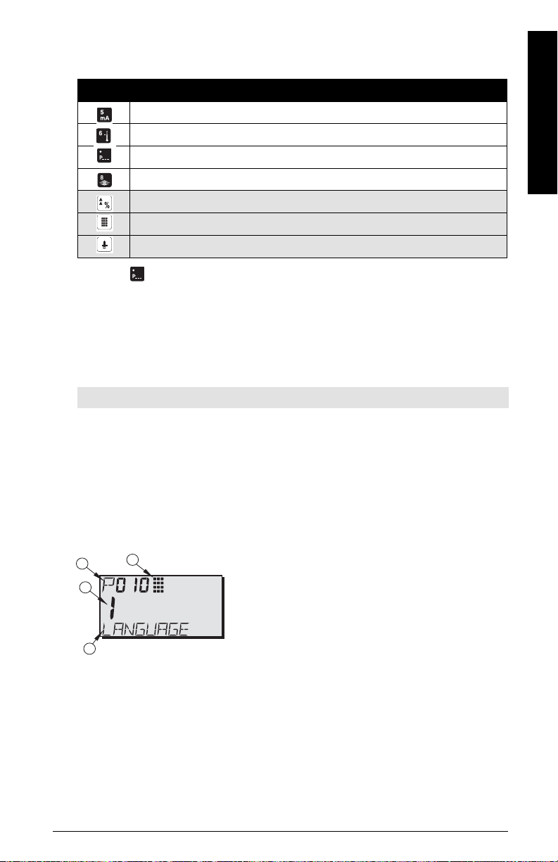
Hand Programmer: function keys in RUN mode
Certain functions can be accessed directly from RUN mode by using specific keys.
Key Run Mode
mA output value displayed in auxiliary reading field
Internal enclosure temperature displayed in auxiliary reading field (P343).
Parameter for auxiliary readings
Displays the value representing Echo Confidence (P805).
Toggle between Units and % on reading display
Initiate and complete PROGRAM mode access
Measurement key displays distance in auxiliary reading field.
1.
Press plus three-digit parameter number, sets parameter to show in the auxiliary display.
1
PROGRAM Mode
Programming
Operation
Note: See
• Set parameters to suit your specific application.
• Activate PROGRAM mode at any time, to change parameter values and set
• For local programming, use the Siemens Milltronics hand programmer.
• For programming from a distance, use either a PC running SIMATIC PDM, or a HART
Accessing a parameter,
operating conditions.
handheld communicator.
on page 18, for detailed instructions.
Display
2
1
4
3
1 – Primary Reading (displays parameter value)
2 – Secondary Reading (displays parameter
number)
3 – Programming indicator
4 – Auxiliary Reading (displays parameter names
for parameters P001 to P010, if a language is
selected. It displays the index value for indexed
parameters, such as P054.)
7ML19985HT01 SITRANS Probe LU – INSTRUCTION MANUAL Page 15
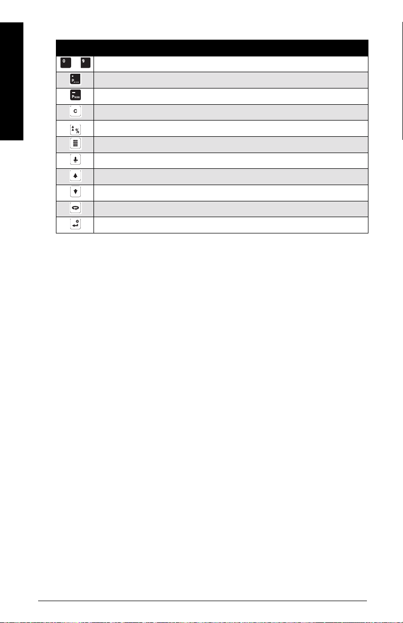
Hand Programmer: function keys in PROGRAM mode
Key Programming Mode
to
Val ues
Decimal point
Operation
Negative value
CLEAR value
TOGGLE between Units and % on parameter value
End PROGRAM session and enable RUN mode
Update echo quality parameters
Parameter scroll-up
Parameter scroll-down
DISPLAY opens parameter fields
ENTER the displayed value
Low temperature effects on RUN/PROGRAM modes
If the internal temperature falls to –30 oC (–22 oF) or below, it will affect both RUN and
PROGRAM modes.
RUN mode will operate normally, with the following exceptions:
• hand programmer operation is disabled
• the LCD displays only limited information: the bar graph and the reliable/
unreliable echo indicator
PROGRAM mode:
• hand programmer operation is disabled
Page 16 SITRANS Probe LU – INSTRUCTION MANUAL 7ML19985HT01
Security
The Lock parameter, P0 00, secures SITRANS Probe LU against changes via the hand
programmer. To enable programming, set P000 to the Unlocked Value stored in P069. To
disable programming, enter a different value.
Note:
• A remote master can still change configuration, if P799 is set to allow this.
Starting PROGRAM mode
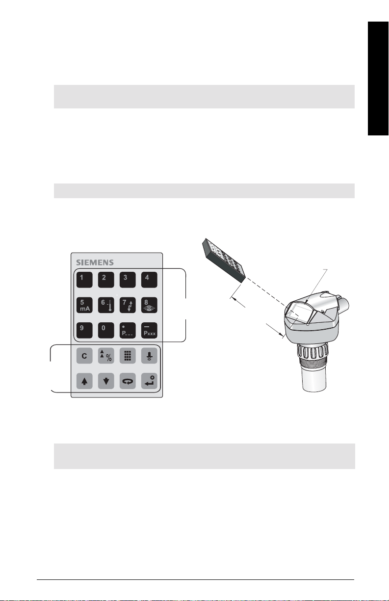
The hand programmer gives you direct access to SITRANS Probe LU.
Hand programmer
Note: For detailed instructions on using the hand programmer, see the next page.
For direct access to SITRANS Probe LU, point the hand programmer at the display from a
maximum distance of 600 mm (2 ft), and press the keys.
hand-held programmer
display
Numeric and
Auxiliary keys
600 mm
(2 ft)
Operation
Function
Keys
Activating SITRANS Probe LU
Note: Keep infrared devices such as laptops, cell phones, and PDAs, away from
SITRANS Probe LU to prevent inadvertent operation.
Power up the instrument. SITRANS Probe LU starts in RUN mode, and detects the
material level, displayed in meters, referenced from Empty (process empty level).
7ML19985HT01 SITRANS Probe LU – INSTRUCTION MANUAL Page 17
Accessing a parameter
Note:
• The following instructions apply when using the Hand Programmer.
• Do not use the Hand Programmer at the same time as SIMATIC PDM, or erratic
operation may result.
Operation
• You do not need to key in initial zeros when entering a parameter number: for
example, for P005, key in 5.
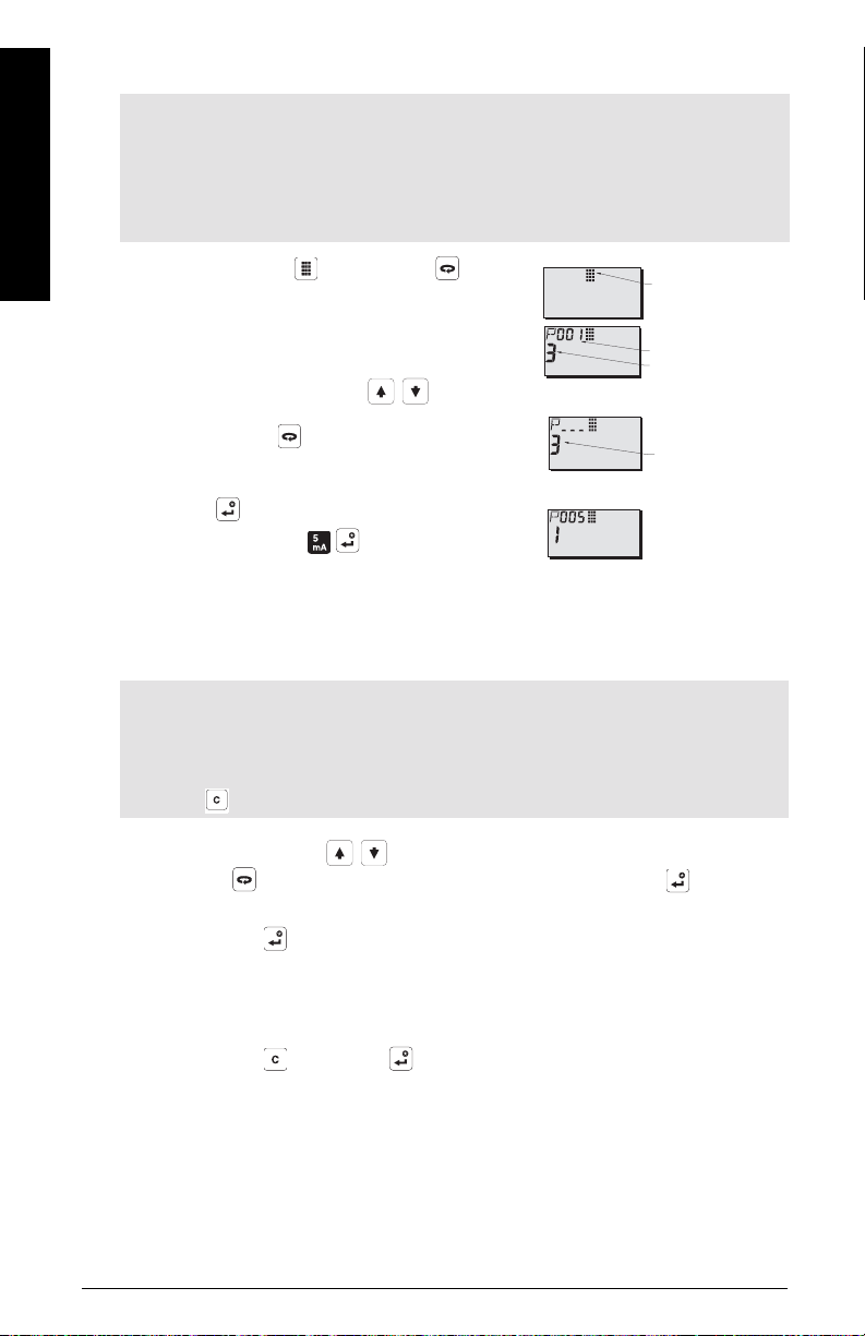
1. Press PROGRAM then DISPLAY to
activate PROGRAM mode.
2. Either use the ARROW keys to scroll to
a different parameter, or
3. Press DISPLAY
Number field.
4. Key in the desired parameter number followed by
ENTER .
For example: press
The LCD displays the new parameter number and
value.
to open the Parameter
.
PROGRAM Icon
Parameter Number
Parameter Value
current value
Changing a Parameter Value
Notes:
• Security must be disabled to enable programming: set P000 to the Unlocked Value
stored in P069. (For more details, see
• Invalid entries will be rejected or limited.
• CLEAR can be used to clear the field
1. U s e t he ARROW keys to scroll to the parameter number, or press
DISPLAY and key in the parameter number followed by ENTER .
2. Key in the new value.
3. Press ENTER to set the value.
P069 Unlocked value
on page 39.)
Parameter Reset to Factory Default
1. Scroll to the parameter or enter its address.
2. Press CLEAR
Page 18 SITRANS Probe LU – INSTRUCTION MANUAL 7ML19985HT01
then ENTER
. The value returns to the default setting.
Master Reset (P999)
Note: Following a Master Reset, complete programming is required.
Resets all parameters to their factory settings, with the following exceptions:
• P000 and P069 are not reset.
• The learned TVT curve is not lost.
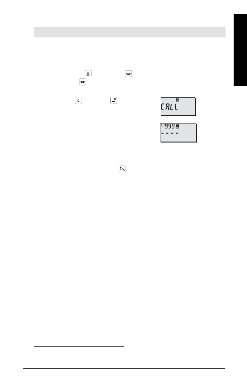
1. Press PROGRAM then DISPLAY to activate PROGRAM mode.
2. Press DISPLAY to open parameter fields.
3. Key in 999.
Press CLEAR then ENTER , to Clear All
and initiate reset. The LCD displays C.ALL.
4. Reset complete. (Reset takes several seconds
to complete.)
Using Units or Percent (%)
Many parameters can be viewed either as a percentage, or in measurement units (P005).
View the parameter, then press MODE to toggle between units and percentage.
Setup Steps (outli ne)
Set the Quick Start parameters between P001 and P010 (the main settings that apply to all
applications and make the system operational). Then set P837 and 838 to ignore false
echoes, and return to RUN mode.
1
1. Select a language option
2. Select the measurement mode: level, space, or distance (P001).
3. Set the response time to level changes (P003).
4. Select units of measurement: m, cm, mm, ft, or in. (P0 05).
5. Set process empty level (Empty: P006).
6. Set the range to be measured (Span: P007).
7. To ignore false echoes before the material echo, set Auto False-Echo Suppression
Distance P838.
8. Enable Auto False-Echo Suppression P837.
9. Return to RUN mode.
, or numeric, for the auxiliary reading (P010).
Operation
1.
The language options are English, German, French, or Spanish. The parameter title appears in
the language selected, for the first 10 parameters.
7ML19985HT01 SITRANS Probe LU – INSTRUCTION MANUAL Page 19

Setup Instructions
Notes:
• The following instructions apply when using the Hand Programmer.
•In PROGRAM mode, you can use the ARROW keys to scroll to a
Operation
parameter number.
• The default parameter values are indicated by an asterisk (*) in the tables.
Using the hand programmer, set each parameter value to suit your application. (For
detailed instructions on accessing a parameter and changing the value, see page18.)
1. Select a language (P01 0: Language)
If a language is selected, parameter
titles for parameters P010 to P001 are
displayed in the auxiliary reading field.
Values
2. Select the measurement mode required for the application (P001: Operation)
0*Numeric/None
1 English
2 German
3 French
4 Spanish
Parameter Auxiliary reading
P00 0
P001
P002
P003
P005
P006
P007
P010
LOCK
OPERATION
MATERIAL
MEAS RESP
UNITS
EMPTY
SPAN
LANGUAGE
Level returns material level referenced from Empty (process empty level).
1*
The reading is returned in volumetric units if parameters 050 to 055 are
Values
set to enable this.
2Space returns material level referenced from Span (process full level).
3
Distance returns material level referenced from the transducer face.
To measure how full the vessel is, select Level: the reading can be returned as level or as
volume (or flow – seeP050 on page 32 for details):
• for a level reading, ensure P050 is set to 0: the reading returns the distance from
process empty level (Empty) to the current level
• for a volume reading, select a vessel shape at P050, and set volume parameters
051 to 055 as required
To measure how much space remains in the vessel, select Space:
• Space returns a reading for the distance between current level and process full
level (Span)
To measure the distance from the transducer face to the current level, select Distance.
Page 20 SITRANS Probe LU – INSTRUCTION MANUAL 7ML19985HT01
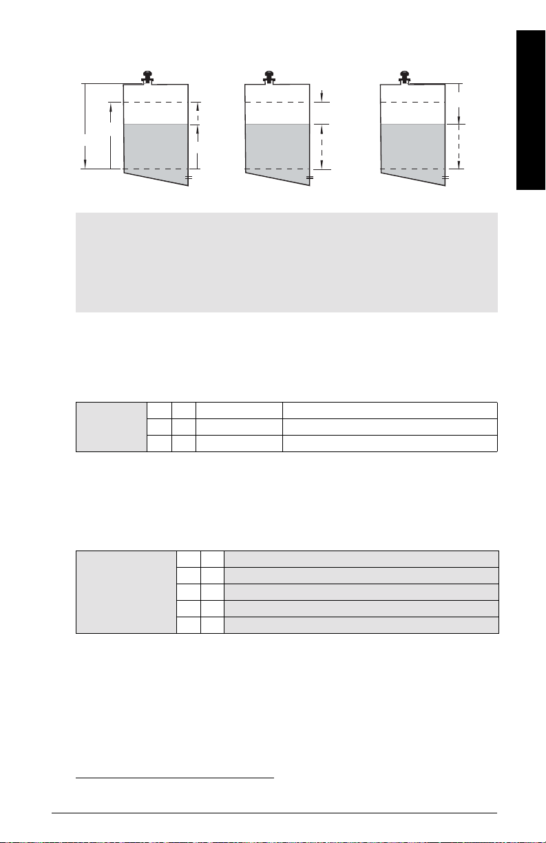
transducer
face
Span
P006
Empty
P007
1
Level
(P001 = 1)
Level
(20 mA)
100%
0%
(4 mA)
Space
(P001 = 2)
Span
Empty
Space
(4 mA)
0%
100%
(20 mA)
Distance
(P001 = 3)
Span
Empty
Notes:
• Setting P001 resets Span (P0 07), unless Span has previously been set to a different
value. Span is set to Empty distance minus 110% of Blanking
to distance measurement (P001 = 3). In this case, Span is set to the same value as
Empty (P006).
• Changing P0 01 may reset Output Function (P201): this applies to HART only.
1
, unless Operation is set
3. Set response time to maximum filling/emptying rate (P003: Measurement Resp on s e )
Set P003 to a measurement response speed just faster than the maximum filling or
emptying rate (whichever is greater).
Values
1* slow 0.100 m/minute
2 medium 1.000 m/minute
3 fast 10.000 m/minute
0%
(4 mA)
Distance
100%
(20 mA)
Operation
Slower settings provide higher accuracy; faster settings allow for more level fluctuation.
(For more detail on measurement response, see
P003 Measurement Response
, on
page 29.)
4. Select type of measurement units required (P005: Units)
1*meters
2
Values
3
4
5
1.
Blanking distance is 0.25 m (10"). See
7ML19985HT01 SITRANS Probe LU – INSTRUCTION MANUAL Page 21
centimeters
millimeters
feet
inches
Blanking Distance
on page 82 for more details.
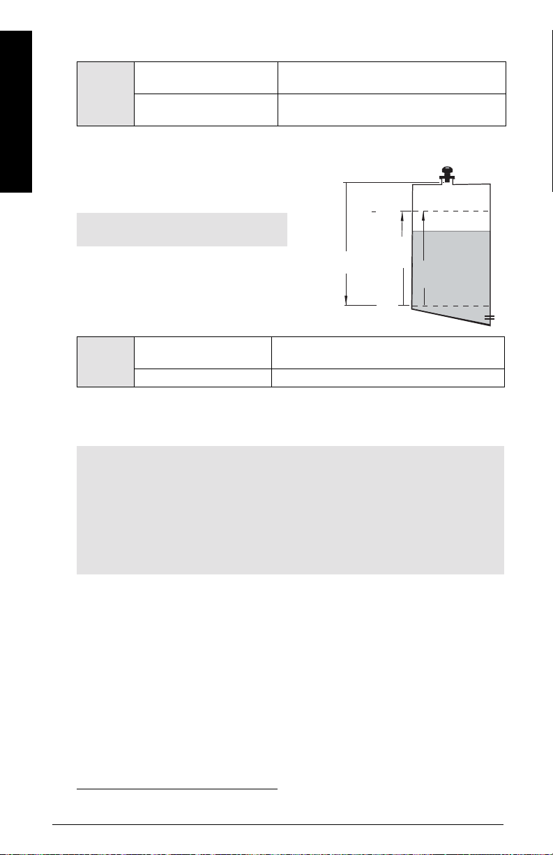
5. Set process empty level (P006: Empty)
Range
Values
Operation
Enter the distance from the transducer face to
(depends on mode)l
Default
process empty level (Empty) using units sets in
P005. Empty can be set to any distance: not
0.0000 to 6.00 m (20 ft) or
0.0000 to 12 m (40 ft)
maximum range:
6.00 0 m (20 ft), or 12.00 0 m (40 ft)
Level Setup
transducer
face
necessarily the bottom of the vessel.
100%
Span
Note: P006 and P007 are interlinked: see
notes attached to P007.
P006
6. Set the range to be measured (P007: Span )
Range
Values
(depends on model
Default 5.725 m (18.78 ft), or 11.725 m (38.47 ft)
Empty
0.0000 to 6.00 m (20 ft) or
0.0000 to 12 m (40 ft)
Enter the distance between Empty (process empty level) and Span (process full level), in
the units set in P005. Span can be set at any distance above the empty level.
P007
Level
0%
1
Notes:
• Setting P006 resets Span, if it has not previously been set to a different value.
• The default setting for Span is based on Operation (P001) and Empty (P006). Span is
set to Empty minus 110% of blanking distance1, unless Operation is set to distance
(P001 = 3). In this case, Span is set to Empty distance.
• Always prevent the monitored surface from approaching within 0.3 m (1 ft) of the
transducer face. This provides a 0.05 m (2") safety margin, as the minimum detectable
distance is 0.25 m (10").
1.
Blanking distance is 0.25 m (10"). See
Blanking Distance
on page 82 for more details.
Page 22 SITRANS Probe LU – INSTRUCTION MANUAL 7ML19985HT01
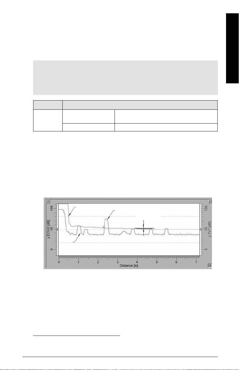
7. Minimize false reflections (P838: Auto False-Echo Suppression Distance)
If SITRANS Probe LU displays an incorrect full level, or if the reading fluctuates between
a false high level and a correct level, you can use the TVT (Time Varying Threshold)
shaper parameters P838 and P837 together to prevent false-echo1 detection. P837 and
P838 elevate the TVT in this region and de-sensitize the receiver from any ’base noise’
caused by internal transducer reflections, nozzle echoes, or other vessel false echoes.
Notes:
• This function works best when the vessel is empty or nearly empty: use it only if
there is a minimum distance of 2 meters from the transducer face to the material.
• Set P837 and P838 during start up, if possible.
• If the vessel contains an agitator, the agitator should be running.
Parameter Values
Range
P838
(depends on model
Default 1.000 m (3.28 ft)
Use P838 in combination with P837. Determine the actual distance from the transducer
face to the material surface. Subtract 0.5 m from this distance and enter the result,
following the Setup Instructions for P837.
0.0000 to 6.00 m (20 ft) or
0.0000 to 12 m (40 ft)
Display before Auto False Echo Suppression
(or when P837 = 0)
Operation
default TVT
Level (db)
1.
False echoes can be caused by obstructions within the beam path. For more detail, see TVT
adjustment parameters, page 57, and TVT curves, page 82.
false
echo
true
echo
Distance (meters)
P839
Hover Level
7ML19985HT01 SITRANS Probe LU – INSTRUCTION MANUAL Page 23
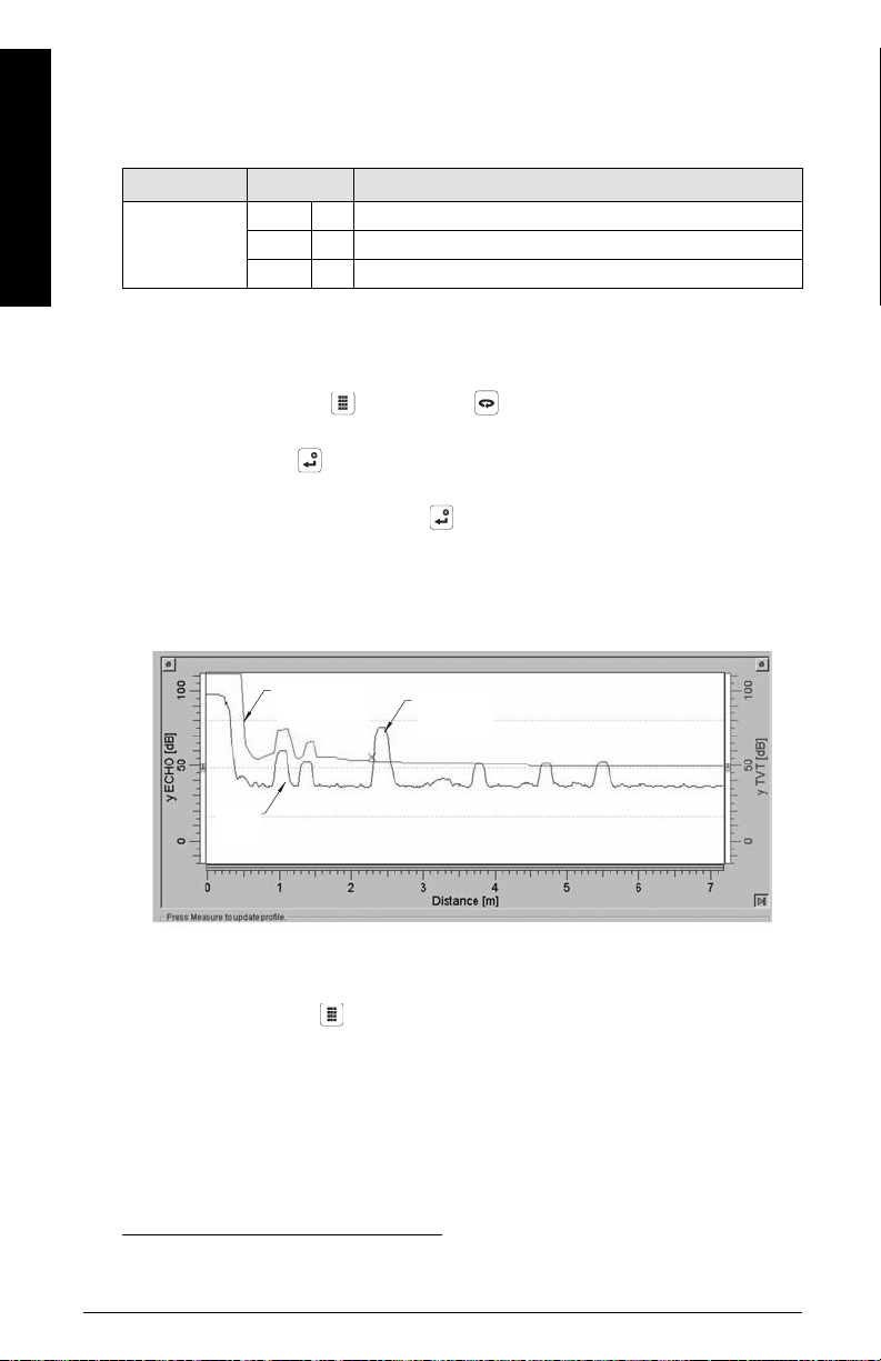
8. Enable False-Echo Suppression (P837: Auto False-Echo Suppression1)
Use this feature to ignore false echoes before the material echo. Use P838 to set the Auto
TVT distance first.
Parameter Values Description
Operation
P837
0*Off
1 Use "learned" TVT
2 "Learn"
Setup Auto False-Echo Suppr essi o n:
a. Perform this function when the vessel is empty or nearly empty.
b. Determine actual distance from transducer face to material level.
c. Press PROGRAM
then DISPLAY
,
.
d. Select P838 and key in [distance to material level minus 0.5 m].
e. Press ENTER .
f. Select P837.
g. Press 2 and then press ENTER . P 837 will automatically revert to 1 (use
Learned TVT) after a few seconds.
Display after Auto False Echo Suppression
TVT curve
(learned)
false
Level (db)
echo
material
level
Distance (meters)
9. Press PROGRAM to return to RUN mode.
1.
False echoes can be caused by obstructions within the beam path. For more detail, see TVT
adjustment parameters, page 57, and TVT curves, page 82.
Page 24 SITRANS Probe LU – INSTRUCTION MANUAL 7ML19985HT01
 Loading...