

Siemens Sitrans Probe LR Operating Instructions Manual
Radar Transmitters
SITRANS Probe LR
Operating Instructions 01/2011
SITRANS

Safety Guidelines: Warning notices must be observed to ensure personal safety as well as that of
others, and to protect the product and the connected equipment. These warning notices are
accompanied by a clarification of the level of caution to be observed.
Qualified Personnel: This device/system may only be set up and operated in conjunction with this
manual. Qualified personnel are only authorized to install and operate this equipment in accordance with
established safety practices and standards.
Unit Repair and Excluded Liability:
• The user is responsible for all changes and repairs made to the device by the user or the user’s
agent.
• All new components are to be provided by Siemens Milltronics Process Instruments.
• Restrict repair to faulty components only.
• Do not reuse faulty components.
Warning: Cardboard shipping package provides limited humidity and moisture protection. This product
can only function properly and safely if it is correctly transported, stored, installed, set up, operated, and
maintained.
This product is intended for use in industrial areas. Operation of this equipment in a residential area
may cause interference to several frequency based communications.
Note: Always use product in accordance with specifications.
Copyright Siemens AG 2011. All Rights
Disclaimer of Liability
Reserved
This document is available in bound version and in
electronic version. We encourage users to purchase
authorized bound manuals, or to view electronic
versions as designed and authored by Siemens
Milltronics Process Instruments. Siemens Milltronics
Process Instruments will not be responsible for the
contents of partial or whole reproductions of either
bound or electronic versions.
While we have verified the contents of this
manual for agreement with the
instrumentation described, variations remain
possible. Thus we cannot guarantee full
agreement. The contents of this manual are
regularly reviewed and corrections are
included in subsequent editions. We welcome
all suggestions for improvement.
Technical data subject to change.
MILLTRONICS®is a registered trademark of Siemens Milltronics Process Instruments.
Contact SMPI Technical Publications European Authorized Representative
at the following address:
Technical Publications Siemens AG
Siemens AG Industry Sector
Siemens Milltronics Process Instruments 76181 Karlsruhe
1954 Technology Drive, P.O. Box 4225 Deutschland
Peterborough, Ontario, Canada, K9J 7B1
Email: techpubs.smpi@siemens.com
• For a selection of Siemens Milltronics level measurement manuals, go to:
www. siemens.com/processautomation. Under Process Instrumentation, select
Measurement
• For a selection of Siemens Milltronics weighing manuals, go to:
www. siemens.com/processautomation. Under Weighing Technology, select
Weighing Systems
and then go to the manual archive listed under the product family.
and then go to the manual archive listed under the product family.
Level
Continuous
© Siemens AG 2011

Table of Contents
Safety Notes ...........................................................................................................................................1
Safety marking symbols ............................................................................................................1
The Manual ............................................................................................................................................1
Application Examples .................................................................................................................2
Support ..........................................................................................................................................2
Abbreviations and Identifications ...........................................................................................2
SITRANS Probe LR ............................................................................................................4
Applications ..................................................................................................................................4
SITRANS Probe LR System Implementation ........................................................................5
Programming ................................................................................................................................5
SITRANS Probe LR Approvals and Certificates ..................................................................5
Specifications ....................................................................................................................7
SITRANS Probe LR ............................................................................................................................... 7
Power............................................................................................................................................. 7
Performance................................................................................................................................. 7
Interface ........................................................................................................................................ 8
Programmer (infrared keypad)................................................................................................ 8
Mechanical................................................................................................................................... 9
Environmental.............................................................................................................................. 9
Process........................................................................................................................................ 10
Approvals (verify against device nameplate)..................................................................... 10
Installation ..................................................................................................................................................11
Mounting location ...............................................................................................................................12
Location on a nozzle, or on a manhole cover ....................................................................14
Mounting Instructions .......................................................................................................................14
SITRANS Probe LR: Dimensions ...........................................................................................15
Wiring ................................................................................................................................16
Power ...........................................................................................................................................16
Connecting SITRANS Probe LR .......................................................................................................16
Operating SITRANS Probe LR .......................................................................................18
RUN Mode ..................................................................................................................................18
Display ......................................................................................................................................... 18
PROGRAM Mode ......................................................................................................................19
Programming.............................................................................................................................. 19
Display ......................................................................................................................................... 19
Low temperature effects on RUN/PROGRAM modes ......................................................20
Security ........................................................................................................................................21
Handheld programmer .............................................................................................................21
Activating SITRANS Probe LR .........................................................................................................22
Accessing a parameter ...........................................................................................................22
Changing a Parameter Value .................................................................................................23
Using Units or Percent (%) ..................................................................................................... 24
Table of Contents
i

Quick Setup for local operation (outline) ......................................................................................24
Setup Instructions .....................................................................................................................24
Additional Settings .............................................................................................................................29
Application Examples ....................................................................................................30
Example 1: Liquid resin in storage vessel, level measurement .....................................30
Example 2: Horizontal vessel with volume measurement ...............................................32
Parameter Reference ....................................................................................................35
Table of C on t en ts
Helpful Hints ............................................................................................................................... 35
To access a parameter and change a value (primary index): ....................................... 35
To access a secondary index and change a value: ......................................................... 36
Quick Start (P001 to P010)................................................................................................................. 38
Volume (P050 to P055)........................................................................................................................ 42
Lock (P069)............................................................................................................................................ 47
Failsafe (P070 to P073)....................................................................................................................... 47
mA Output (P201 to P215).................................................................................................................. 48
Installation Records (P341 to P346) ................................................................................................ 52
Range Calibration (P652 to P655) .................................................................................................... 53
Rate (P700 and P701).......................................................................................................................... 55
Measurement Verification (P709 to P713) ................................................................................... 56
Communications (P799)..................................................................................................................... 59
Echo Processing (P800 to P807) .................................................................................................
Algorithm (P820) .................................................................................................................................. 62
TVT (Time Varying Threshold) Adjustment Parameters (P831 to P839) ............................... 63
Test (P900 to P924) ............................................................................................................................. 66
Measurement ...................................................................................................................................... 67
..... 59
ii

Appendix A: Alphabetical Parameter List .................................................................69
Appendix B: Programming Chart ..................................................................................72
Appendix C: HART ...........................................................................................................75
HART Communications for SITRANS Probe LR ...........................................................................75
HART Electronic Device Description (EDD) .................................................................................75
HART Communicator 275/375: ................................................................................................76
SIMATIC Process Device Manager (PDM) ..................................................................................79
Maintenance settings (accessible via PDM only) ............................................................79
HART Version .......................................................................................................................................80
Burst mode .................................................................................................................................80
Appendix D: Troubleshooting .......................................................................................81
Communication Troubleshooting ....................................................................................................81
Generally: ....................................................................................................................................81
Specifically: .................................................................................................................................81
General Fault Codes ...........................................................................................................................82
Fault Codes (Firmware Revision 3.02 or higher) ..........................................................................82
Fault Codes (Firmware Revision 1.05 or earlier) ..........................................................................85
Operation Troubleshooting ...............................................................................................................88
Maintenance ....................................................................................................................91
Unit Repair and Excluded Liability ..................................................................................................91
Appendix E: Technical Reference ................................................................................92
Principles of Operation ......................................................................................................................92
Transceiver ...........................................................................................................................................92
Typical Receiver Signal ........................................................................................................... 93
Near Blanking ............................................................................................................................93
Loss of Echo (LOE) ..............................................................................................................................93
Range Extension ........................................................................................................................94
False-Echo Suppression ...................................................................................................................94
TVT (Time Varying Threshold) curves ............................................................................................94
Auto False-Echo Suppression ................................................................................................94
RUN/PROGRAM ..................................................................................................................................96
Output ...........................................................................................................................................96
Failsafe ..................................................................................................................................................97
Chemical compatibility .......................................................................................................................97
Appendix F: Special Applications ................................................................................98
Application Example: Stilling-well .........................................................................................98
Appendix G: hazardous area installations ...............................................................100
Wiring Details ....................................................................................................................................100
Intrinsically Safe Model .........................................................................................................100
FM/CSA ......................................................................................................................................101
EU Equivalency ....................................................................................................................... 101
Loop Voltage versus Loop Resistance ...............................................................................102
IS Safety Barrier Selection ...................................................................................................102
How to select a passive barrier for SITRANS Probe LR .............................................. 102
PLC Input Modules................................................................................................................. 103
Passive Shunt Diode Barriers ............................................................................................ 103
Active barriers (repeating barriers)................................................................................... 103
Table of Contents
iii

Instructions specific to hazardous area installations ..............................................................104
(Reference European ATEX Directive 94/9/EC, ................................................................104
Annex II, 1/0/6) .........................................................................................................................104
Product Nameplate ..........................................................................................................................105
Intrinsically safe connection drawing (FM) ................................................................................106
Intrinsically safe connection drawing (CSA) ..............................................................................107
Non-incendive connection drawing (FM) ...................................................................................108
Appendix H: Firmware Revision History ...................................................................109
Table of C on t en ts
Glossary ..........................................................................................................................111
Index ................................................................................................................................115
iv
Safety Notes
Special attention must be paid to warnings and notes highlighted from the rest of the text
by grey boxes.
1
WARNING: relates to a caution symbol on the product, and means
that failure to observe the necessary precautions can result in death,
serious injury, and/or considerable material damage.
WARNING
1
: means that failure to observe the necessary
precautions can result in death, serious injury, and/or considerable
material damage.
Note:
means important information about the product or that part of the operating
manual.
Safety marking symbols
In manual: On product: Description
Earth (ground) Terminal
(Label on product: yellow background.) WARNING: refer
to accompanying documents (manual) for details.
The Manual
SITRANS Probe LR
Notes:
• Please follow the installation and operating procedures for a quick, trouble-free
installation and to ensure the maximum accuracy and reliability of your
SITRANS Probe LR.
• This manual applies to the SITRANS Probe LR only.
• This product is intended for use in industrial areas. Operation of this equipment in a
residential area may cause interference to several frequency based
communications.
This manual will help you set up your SITRANS Probe LR for optimum performance. We
always welcome suggestions and comments about manual content, design, and
accessibility.
Please direct your comments to techpubs.smpi@siemens.com
measurement manuals, go to www.siemens.com/level
Measurement.
1.
This symbol is used when there is no corresponding symbol on the product.
7ML19985HR02 SITRANS Probe LR – INSTRUCTION MANUAL Page 1
. For other Siemens level
, and look under Level

WARNING: Changes or modifications not expressly approved by
Siemens could void the user’s authority to operate the equipment.
Note:
This equipment has been tested and found to comply with the limits for a
Class A digital device, pursuant to Part 15 of the FCC Rules. These limits are designed to
provide reasonable protection against harmful interference when the equipment is
operated in a commercial environment. This equipment generates, uses, and can
radiate radio frequency energy and, if not installed and used in accordance with the
instruction manual, may cause harmful interference to radio communications.
Operation of this equipment in a residential area is likely to cause harmful interference,
in which case the user will be required to correct the interference at his own expense.
Application Examples
The application examples used in this manual illustrate typical installations using
SITRANS Probe LR. Because there is often a range of ways to approach an application,
other configurations may also apply.
SITRANS Probe LR
In all examples, substitute your own application details. If the examples do not apply to
your application, check the applicable parameter reference for the available options.
Standard applications are found in the main body of the manual: for more specialized
applications, please see
Support
If you have questions you can access our 24-hour hotline at:
www.siemens.com/automation/support-request
Appendix F: Special Applications
.
, page 98.
Phone: +49 180 50 50 222
Abbreviations and Identifications
Short
form
A/D Analog to digital
CE / FM /
CSA
C
i
D/A Digital to analog
DAC Digital Analog Converter
DCS Distributed Control System control room apparatus
Page 2 SITRANS Probe LR – INSTRUCTION MANUAL 7ML19985HR02
Long Form Description Units
Conformitè Europèene / Factory
Mutual / Canadian Standards
Association
Internal capacitance
safety approval

Short
form
Long Form Description Units
FV Full Vacuum
ESD Electrostatic Discharge
HART
I
i
I
o
Highway Addressable Remote
Trans duc er
Input current mA
Output current mA
IS Intrinsically Safe safety approval
L
i
Internal inductance mH
LRV Lower Range Value value for process empty level 4 mA
LSL Lower Sensor Limit
mH MilliHenry 10
μF MicroFarad 10
μs Microsecond 10
below which no PV is
anticipated
-3
-6
-6
Henry
Farad
Second
PBT Polybutylene terephthalate
PED Pressure Equipment Directive safety approval
PEI Polyether Imide
pF Pico Farads 10
-12
Farad
ppm Parts per Million
PV Primary Variable measured value
SELV Safety Extra Low Voltage
SV Secondary Variable equivalent value
TV Transmitter Variable
TVT Time Varying Threshold sensitivity threshold
U
i
U
o
Input voltage V
Output voltage V
URV Upper Range Value value for process full level 20 mA
USL Upper Sensor Limit
a.
100% is most commonly set to 20 mA, and 0% to 4 mA: however, the settings
above which no PV is
anticipated
can be reversed.
SITRANS Probe LR
a
a
7ML19985HR02 SITRANS Probe LR – INSTRUCTION MANUAL Page 3
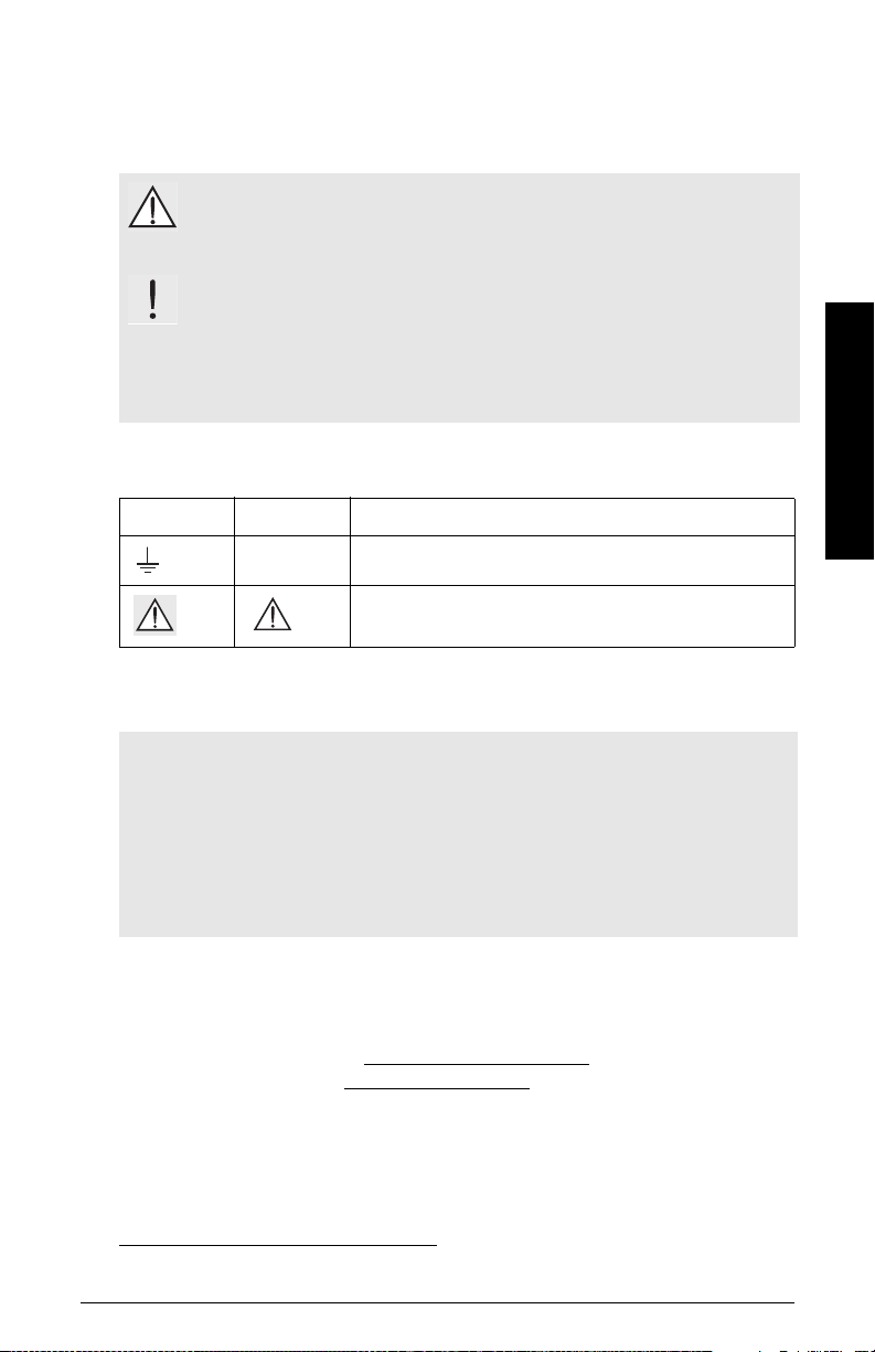
SITRANS Probe LR
shield length: 100 mm (4"):
use for nozzles of 100 mm (4") or less
in length
shield length 250 mm (10"):
use for long nozzles of 250 mm (10")
or less in length
SITRANS Probe LR is a 2-wire loop-powered, continuous level measuring instrument that
utilizes advanced pulse radar technology at 5.8 GHz (6.3 GHz in North America). The
instrument consists of an electronic component coupled to the antenna and process
connection. It is very easy to install and set up, using either the infrared handheld
programmer locally, or using SIMATIC
Communication is via HART
been field-proven in over 500,000 applications worldwide (ultrasonic and radar).
SITRANS Probe LR is available in two versions
• General Purpose (non-hazardous)
• Intrinsically Safe (with suitable barrier)
2
. Signals are processed using Sonic Intelligence® which has
Applications
1
PDM from a remote location.
SITRANS Probe LR
Notes:
• Please refer to product label for approval information.
• SITRANS Probe LR is to be used only in the manner outlined in this manual,
otherwise protection provided by the equipment may be impaired.
SITRANS Probe LR is designed to measure liquid levels in a variety of applications:
• liquid bulk storage vessels
• simple process vessels with gentle agitation
• liquids
• slurries
1.
SIMATIC®is a registered trademark of Siemens AG.
2.
HART® is a registered trademark of the HART Communication Foundation.
Page 4 SITRANS Probe LR – INSTRUCTION MANUAL 7ML19985HR02
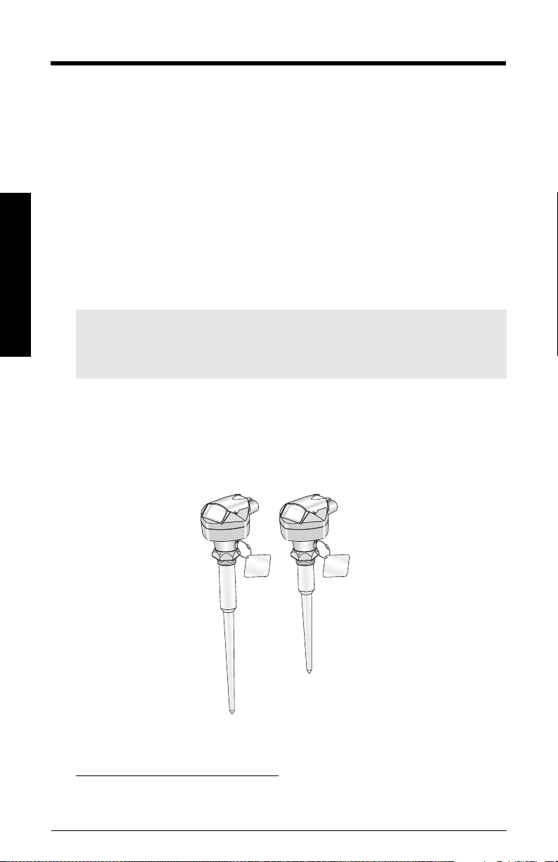
SITRANS Probe LR System Implementation
active PLC
HART modem
SITRANS
Probe LR
power supply
1
Typical PLC/mA configuration with HART
R2= 250 Ω
HART
communicator
SITRANS Probe LR1supports HART2communication protocol and SIMATIC PDM
software.
SITRANS Probe LR
Programming
SITRANS Probe LR carries out its level measurement function according to the set of
built-in parameters. You can make parameter changes via the handheld programmer, via
a PC using SIMATIC PDM, or via a HART Handheld Communicator.
SITRANS Probe LR Approvals and Certificates
Note: Please see
approvals listing.
1.
Depending on the system design, the power supply may be separate from the
PLC, or integral to it.
2.
A 250 Ohm resistor may be required if the loop resistance is less than 250 Ohms.
7ML19985HR02 SITRANS Probe LR – INSTRUCTION MANUAL Page 5
Approvals (verify against device nameplate)
on page 10 for an

SITRANS Probe LR
Notes
Page 6 SITRANS Probe LR – INSTRUCTION MANUAL 7ML19985HR02

Specifications
Notes:
• Siemens makes every attempt to ensure the accuracy of these specifications but
reserves the right to change them at any time.
• Please check the ambient and operating temperatures under
and
Approvals (verify against device nameplate)
(verify against device nameplate)
about to use or install.
on page 10, for the specific configuration you are
SITRANS Probe LR
Power
on page 10; also check
Enclosure
on page 9,
Approvals
Nominal 24 V DC at
max. 550 Ohm.
• Maximum 30 V DC
• 4 to 20 mA
For other configurations, see the chart
versus Loop Resistance
on page 102.
Performance
Reference operating conditions according to IEC 60770-1
• ambient temperature +15 to +25 oC (+59 to +77 oF)
• humidity 45% to 75% relative humidity
• ambient pressure 860 to 1060 mbar g (86000 to 106000 N/m
Measurement Accuracy (measured in accordance with IEC 60770-1)
• non-linearity (accuracy) the greater of: 10 mm (0.4"), or 0.10% of Span
(including hysteresis and non-repeatability)
• non-repeatability 5 mm (included in non-linearity specification)
• deadband (resolution) 5 mm (included in non-linearity specification)
Analog Output Accuracy (measured in accordance with IEC 60770-1)
• non-linearity (accuracy) 0.125% of Span (including hysteresis and nonrepeatability)
• non-repeatability 0.025% of Span (included in non-linearity
specification)
• deadband (resolution) 0.0375% of Span (included in non-linearity
specification)
Loop Voltage
2
g)
Specifications
7ML19985HR02 SITRANS Probe LR – INSTRUCTION MANUAL Page 7

Frequency 5.8 GHz (6.3 GHz in N. America): refer to product
Max. measurement range
Update time mA output and loop display is updated once per
Minimum detectable distance
Influence of ambient temperature 0.003% / K
Dielectric constant εr > 3 (for < 3 use waveguide antenna or stillpipe)
Memory:
• non-volatile EEPROM
• no battery required.
Interface
•HART
• configuration: Siemens SIMATIC PDM (PC), or
HART handheld communicator, or
Siemens infrared handheld programmer
• analog output: 4 to 20 mA, ± 0.02 mA accuracy
• display (local): multi-segment alphanumeric liquid crystal with bar graph
Programmer (infrared keypad)
Specifications
Siemens Milltronics Infrared IS (Intrinsically Safe) Handheld Programmer for hazardous
and all other locations (battery is non-replaceable)
nameplate for confirmation
1)
20 m (65 ft)
second
1)2)
0.3 m (1 ft), plus the shield length (if any)
(representing level)
• approval: ATEX II 1 G, EEx ia IIC T4, certificate SIRA 01ATEX2147
FM/CSA Class 1, Div. 1, Groups A, B, C, D
• ambient temperature: −20 to +40 °C (−5 to +104 °F)
• interface: proprietary infrared pulse signal
• power: 3 V lithium battery
• weight: 150 g (0.3 lb)
•color: black
1.
Referenced from the sensor reference point.
2.
See 'Near Blanking' on page 93 for more details.
Page 8 SITRANS Probe LR – INSTRUCTION MANUAL 7ML19985HR02

Mechanical
Process Connections:
• threaded connection 1.5” NPT, BSP, or G (BS EN ISO 228-1)
Antenna:
• polypropylene rod hermetically sealed construction
standard 100 mm (4") shield for maximum 100 mm (4") nozzle,
or optional 250 mm (10") long shield
Notes:
• Please check the ambient and operating temperatures under
Approvals (verify against device nameplate)
and
(verify against device nameplate)
about to use or install.
• The use of approved watertight conduit hubs/glands is required for Type 4X /
NEMA 4X, Type 6 / NEMA 6, IP67, IP68 (outdoor applications).
Enclosure
• body construction PBT (polybutylene terephthalate)
• lid construction hard-coated PEI (polyether imide)
• conduit entry 2 x M20x1.5 (plastic strain relief) or 2 x 1/2" NPT thread
• ingress protection Type 4X / NEMA 4X, Type 6 / NEMA 6, IP67, IP68 (see note
on page 10, for the specific configuration you are
below)
on page 10; also check
Enclosure
on this page,
Approvals
Specifications
Weight:
• standard model
1
1.97 kg (4.35 lb.)
Environmental
• location: indoor/ outdoor
• altitude: 5000 m (16,404 ft) max.
• ambient temperature: −40 to +80 °C (−40 to +176 °F)
• relative humidity: suitable for outdoor
Type 4X / NEMA 4X, Type 6 / NEMA 6, IP67, IP68 enclosure
(see note below)
• installation category: I
• pollution degree: 4
1.
Unit with 100 mm (4") rod and adaptors
7ML19985HR02 SITRANS Probe LR – INSTRUCTION MANUAL Page 9

Process
•temperature: −40 to +80 °C (−40 to +176 °F).
(at process connection)
• pressure (vessel): maximum 3 bar, gauge (43.5 psi, gauge)
Notes:
• Please check the ambient and operating temperatures under
and
Approvals (verify against device nameplate)
(verify against device nameplate)
on page 10, for the specific configuration you are
on page 10; also check
about to use or install.
• The use of approved watertight conduit hubs/glands is required for Type 4X /
NEMA 4X, Type 6 / NEMA 6, IP67, IP68 (outdoor applications).
Enclosure
Approvals (verify against device nameplate)
•General CSA
• Radio Europe (R&TTE), FCC, Industry Canada
• Hazardous Intrinsically Safe: (Europe) ATEX II 1 G, EEx ia IIC T4
(US/Canada) FM/CSA: (barrier required)
Class I, Div. 1, Groups A, B, C, D
Class II, Div. 1, Groups E, F, G
Class III T4
, FM, CE, C-TICK
US/C
on this page,
Approvals
1
(Australia) ANZEx Ex ia IIC T4
o
C) IP67, IP68
Specifications
(Tamb = –40 to +80
(International) IECEx TSA 04.0020X Ex ia IIC T4
(Brazil) INMETRO: BR-Ex ia IIC T4
2
Non-incendive: (US) FM
:
Class I, Div. 2, Groups A, B, C, D T5
• Marine Lloyd’s Register of Shipping
ABS Type Approval
Note: EN 6100 0-4-3 (CE EMC) testing was conducted on the SITRANS Probe LR while
mounted in a metallic vessel.
1.
See 'Intrinsically safe connection drawing (FM)' on page 106 for drawing number 23651611, or
'Intrinsically safe connection drawing (CSA)' on page 107 for drawing number 23651621.
2.
See 'Non-incendive connection drawing (FM)' on page 108 for drawing number 23650537.
Page 10 SITRANS Probe LR – INSTRUCTION MANUAL 7ML19985HR02

Installation
1
WARNINGS:
• Installation shall only be performed by qualified personnel and in
accordance with local governing regulations.
• SITRANS Probe LR ‘is to be used only in the manner outlined in this
manual, otherwise protection provided by the device may be impaired.
• Never attempt to loosen, remove, or disassemble process connection
or instrument housing while vessel contents are under pressure.
• This product is designated as a Pressure Accessory per Directive 97/ 23
/ EC and is not
• Materials of construction are chosen based on their chemical
compatibility (or inertness) for general purposes. For exposure to
specific environments, check with chemical compatibility charts
before installing.
• The user is responsible for the selection of bolting and gasket materials
which will fall within the limits of the flange and its intended use and
which are suitable for the service conditions.
• Improper installation may result in loss of process pressure.
Notes:
• Refer to the device nameplate for approval information.
• The Process Device Tag shall remain with the process pressure boundary
assembly1. In the event the instrument package is replaced, the Process Device Tag
shall be transferred to the replacement unit.
• SITRANS Probe LR units are hydrostatically tested, meeting or exceeding the
requirements of the ASME Boiler and Pressure Vessel Code and the European
Pressure Equipment Directive.
• The serial numbers stamped in each process connection body provide a unique
identification number indicating date of manufacture.
Example: MMDDYY – XXX (where MM = month, DD = day, YY = year, and
Further markings (space permitting) indicate flange configuration, size, pressure
class, material, and material heat code.
intended for use as a safety device.
XXX= sequential unit produced
Installation
1.
The process pressure boundary assembly comprises the components that act as a barrier
against pressure loss from the process vessel: that is, the combination of process connection
body and emitter, but normally excluding the electrical enclosure.
7ML19985HR02 SITRANS Probe LR – INSTRUCTION MANUAL Page 11
Mounting location
process temperature:
–40 to 80
o
C (–40 to 176 oF)
ambient temperature
(surrounding enclosure volume)
–40 to 80
o
C (–40 to 176 oF)
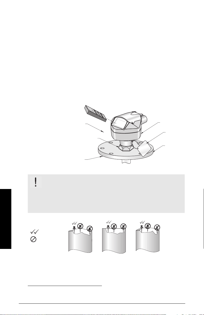
handheld programmer
nameplate
location
process
device tag
customersupplied
flange
locking collar
1
over threaded connection;
secured by three 2 mm Allen set-screws
Coni
Fl at
Flat Parabolic Conical
preferred
undesirable
Recommendations:
• Ensure ambient temperature is within –40 to 80 oC (–40 to 176 oF).
• Provide easy access for viewing the display and programming via the handheld
programmer.
• Ensure the environment is suitable to the housing rating and materials of
construction.
Precautions:
• Avoid proximity to high voltage or current wiring, high voltage or current contacts,
and to variable frequency motor speed controllers.
• Avoid interference to the emission cone from obstructions or from the fill path.
• Avoid central locations on vessels.
1
WARNING: For vessels with conical or parabolic tops, avoid
mounting the instrument at the centre. (The concavity of the top can
focus echoes into the centre, giving false readings.)
Note:
Under certain circumstances, it may be acceptable to mount SITRANS Probe LR
at the centre of a flat-topped tank: please discuss this with your Siemens Milltronics
representative.
Installation
1.
PPage 12 SITRANS Probe LR – INSTRUCTION MANUAL 7ML19985HR02
When the locking collar is secured, it prevents the enclosure rotating on the threaded
connection.
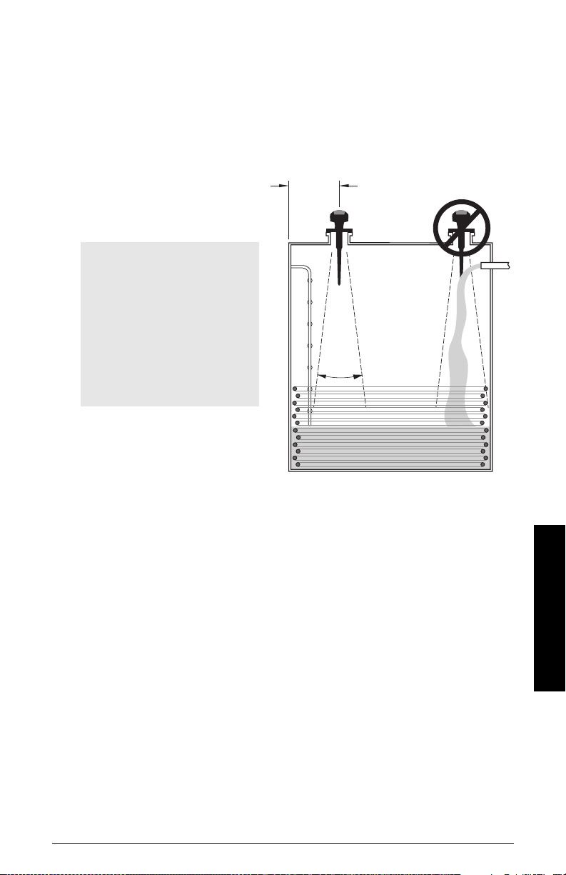
Keep the emission cone free of interference:
minimum of 300 mm (1ft) for
every 3 m (10 ft) of vessel height.
beam
angle
28
o
Notes:
• Beam angle is defined at the
-3dB boundary, or 1/2 signal
level. Obstructions outside of
the beam may still be detected,
depending on the size, shape,
or distance from the antenna.
• For more detail on false
echoes, see
False-Echo
Suppression
on page 94.
• Make allowance for the emission cone spreading: allow a minimum of 300 mm (1 ft)
for every 3 m (10 ft) of vessel height.
• Locate the antenna away from the side wall, to avoid interference from indirect
echoes.
• Avoid interference from objects such as ladders or pipes, which can cause false
echoes.
• Make sure the beam angle does not intersect the fill path.
7ML19985HR02 SITRANS Probe LR – INSTRUCTION MANUAL Page 13
Installation
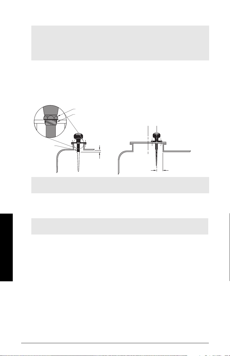
Location on a nozzle, or on a manhole cover
100 mm (4")
10 mm
(0.4")
locking collar secured by three 2 mm Allen set-screws
threaded connection
shield
Notes:
• Use the 100 mm (4") shield on nozzles that are 100 mm (4") in length, or shorter.
• Use the 250 mm (10") shield on nozzles that are 250 mm (10") in length, or shorter.
• If your nozzle is longer than 250 mm (10"), contact your local representative. You will
need to exchange the device for a different model with a longer shield length.
On a nozzle, the end of the shield section should protrude a minimum of 10 mm (0.4”) to
avoid interference.
A manhole cover is typically a covered nozzle with a diameter of 610 mm (24”) or greater.
To provide optimum signal conditions on a manhole cover, locate the antenna off-center,
typically 100 mm (4") from the side.
Note: For details on other applications, see
page 98.
Appendix F: Special Applications
Mounting Instructions
Note: Do not rotate the enclosure after programming and vessel calibration, otherwise
an error may occur, caused by a polarity shift of the transmit pulse.
1. Before inserting SITRANS Probe LR into its mounting connection, check to ensure
the threads are matching, to avoid damaging them.
Installation
2. Simply screw SITRANS Probe LR into the process connection, and hand tighten. For
pressure applications, it will be necessary to use PTFE tape (or other appropriate
thread sealing compound) and tighten the process connection beyond hand tight.
The maximum torque is 40 N-m (30 ft.lbs.).
3. If you want to rotate the enclosure, use a 2 mm Allen key to loosen the three setscrews that secure the locking collar.
4. Once the enclosure is in a suitable position, tighten the set-screws.
PPage 14 SITRANS Probe LR – INSTRUCTION MANUAL 7ML19985HR02
on
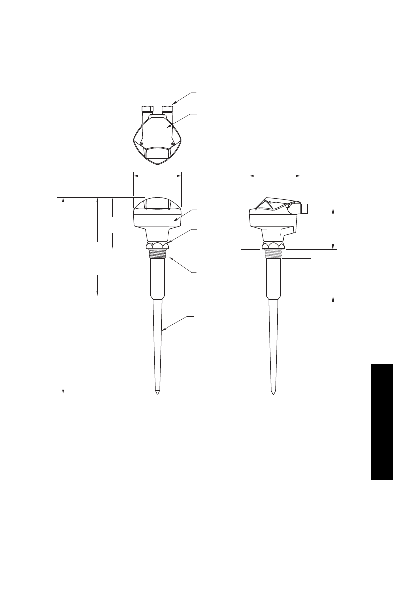
SITRANS Probe LR: Dimensions
reference
point
hinged lid
enclosure/
electronics
polypropylene
rod antenna
(internal) shield length
standard: 100 mm (4")
[optional: 250 mm (10")]
std. 273 mm (10.8") min.
option 423 mm (16.7") max.
134 mm
(5.3")
129 mm
(5.1")
139 mm
(5.5")
mounting thread
1/2" NPT thread
(or M20 plastic strain relief)
locking collar
103.5 mm
(4")
std. 552 mm (21.7") min.
option 702 mm (27.6") max.
23 mm (0.9")
std. 139 mm (5.47")
[optional 289 mm (11.38")]
7ML19985HR02 SITRANS Probe LR – INSTRUCTION MANUAL Page 15
Installation
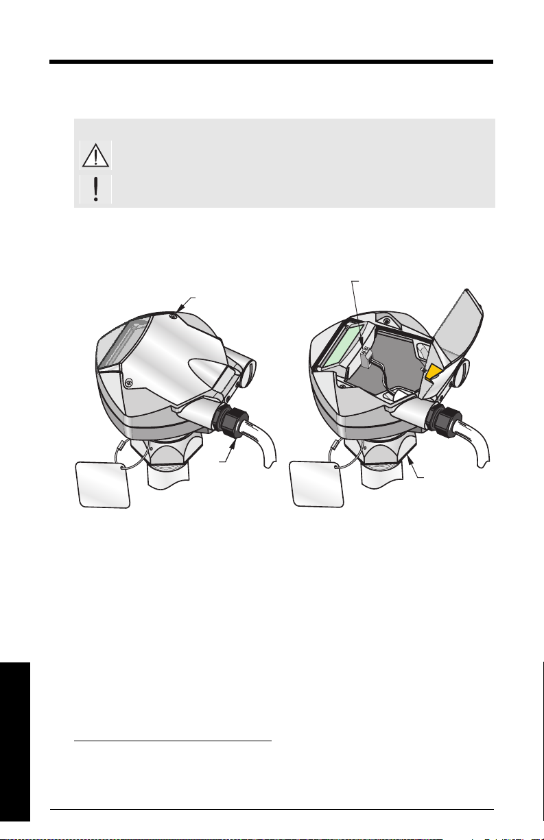
Wiring
locking collar
terminal block
lid screw (1 of 2)
Unscrew the two lid screws to access the
terminal block.
strain
relief
2
(or NPT cable entry)
Power
WARNINGS:
dc terminals shall be supplied from an SELV
with IEC-1010-1 Annex H.
All field wiring must have insulation suitable for rated voltages.
Connecting SITRANS Probe LR
1
source in accordance
1,2
,
Wiring
,
1.
Safety Extra Low Voltage
2.
If cable is routed through conduit, use only approved suitable-size hubs for
waterproof applications.
Page 16 SITRANS Probe LR – INSTRUCTION MANUAL 7ML19985HR02

Notes:
• Use shielded, twisted pair cable (wire gauge AWG 14 to 22).
• Separate cables and conduits may be required to conform to standard
instrumentation wiring practices or electrical codes.
• The non-metallic enclosure does not provide a continuous ground path between
conduit connections: use grounding type bushings and jumpers.
• For detailed information on Intrinsic Safety setups, see
Wiring Details
1. If you want to rotate the enclosure, use a 2 mm Allen key to loosen the 3 Allen setscrews securing the locking collar. Position the unit and retighten the screws.
2. Strip the cable jacket for approximately 70 mm from the end of the cable, and thread
the wires through the strain relief
1
.
3. Connect the wires to the terminals: the polarity
is identified on the terminal block.
4. Tighten the strain relief to form a good seal.
5. Close the lid and tighten screws: please do not
overtighten screws. (Recommended torque is
1.1 to 1.7 N-m (10 to 15 in-lb) of torque.)
on page 100.
1.
If cable is routed through conduit, use only approved suitable-size hubs for
waterproof applications.
7ML19985HR02 SITRANS Probe LR – INSTRUCTION MANUAL Page 17
Wiring
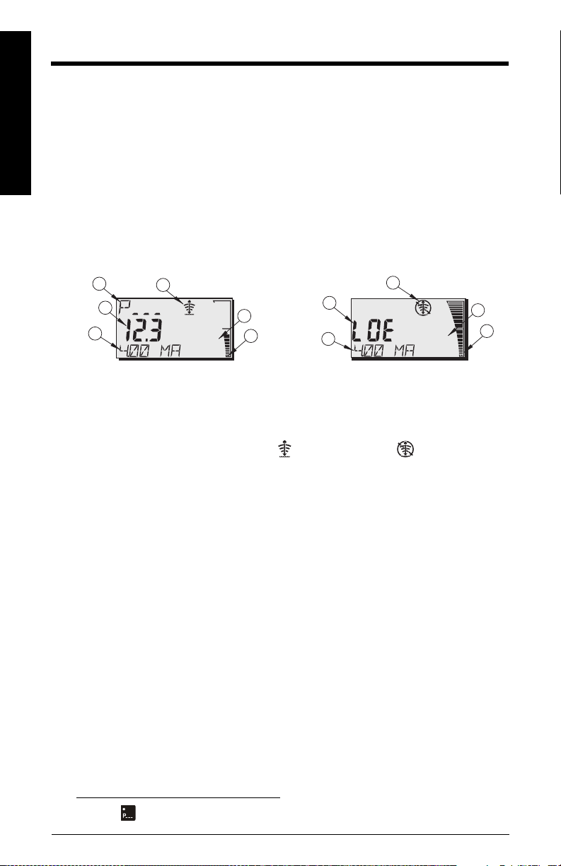
Operating SITRANS Probe LR
m
m
Normal operation Failsafe operation
1
3
4
5
1
3
4
5
2
6
6
SITRANS Probe LR has two modes of operation: RUN and PROGRAM.
RUN Mode
Operation
SITRANS Probe LR automatically starts in RUN mode when power is applied, and detects
the material level. The primary reading displays the material level (in meters) referenced
from Empty (process empty level). This is the default start-up display mode.
System status is displayed on the LCD, or on a remote communications terminal.
Display
1 – Primary Reading (displays level, distance, or volume, in either units or percent)
2 – Secondary Reading (displays Parameter number for Auxiliary Reading1)
3 – Echo status indicator: Reliable Echo or Unreliable Echo
4 – Units or Percent
5 – Active bar graph represents material level
6 – Auxiliary Reading (depending on the parameter selected, it displays milliAmp value,
distance or confidence, with units where applicable)
If the echo confidence drops below the echo confidence threshold, the failsafe timer
starts running. When the timer expires, the letters LOE (Loss of Echo) alternate with the
reading every two seconds, and the Reliable Echo indicator is replaced by the Unreliable
Echo indicator. When a valid reading is received, the level reading display returns to
normal operation.
1.
Press to display the auxiliary reading field when in RUN mode.
Page 18 SITRANS Probe LR – INSTRUCTION MANUAL 7ML19985HR02
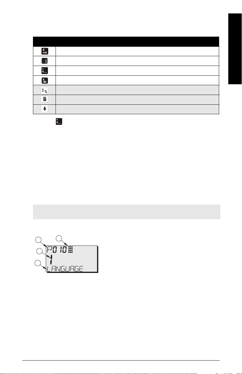
Handheld Programmer: function keys in RUN mode
6
1 – Primary Reading (displays parameter value)
2 – Secondary Reading (displays parameter number)
3 – Programming indicator
4 – Auxiliary Reading (displays parameter names for
the Quick Start parameters, if a language is
selected. It displays the index value for indexed
parameters, such as P054.)
1
2
3
4
Certain functions can be accessed directly from RUN mode by using specific keys.
Key Run Mode
mA output value displayed in auxiliary reading field.
Internal enclosure temperature displayed in auxiliary reading field.
a
Parameter for auxiliary readings
Displays the value representing Echo Confidence (P805).
Toggle between Units and % on reading display.
Initiate and complete PROGRAM mode access.
Distance displayed in auxiliary reading field.
a.
Press plus three-digit parameter number to set parameter to show in the auxiliary display.
.
PROGRAM Mode
Programming
• Set parameters to suit your specific application.
•Activate PROGRAM mode at any time, to change parameter values and set
operating conditions.
• For local programming, use the Siemens handheld programmer.
• For programming from a distance, use either a PC running SIMATIC PDM, or a HART
handheld communicator.
Operation
Note: Do not use the handheld programmer at the same time as SIMATIC PDM, or
erratic operation may result.
Display
7ML19985HR02 SITRANS Probe LR – INSTRUCTION MANUAL Page 19
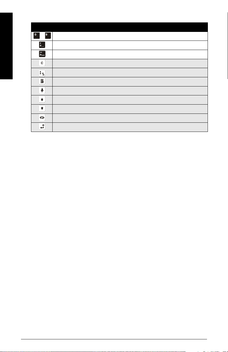
Handheld Programmer: function keys in PROGRAM mode
Key Programming Mode
to
Val ues
Decimal point
Operation
Negative value
CLEAR value
TOGGLE between Units and % on parameter value
End PROGRAM session and enable RUN mode
Update echo quality parameters
Parameter scroll-up
Parameter scroll-down
DISPLAY opens parameter fields
ENTER the displayed value
Low temperature effects on RUN/PROGRAM modes
If the internal temperature falls to –30 oC (–22 oF) or below, it will affect both RUN and
PROGRAM modes.
RUN mode will operate normally, with the following exceptions:
• handheld programmer operation is disabled
• the LCD displays only limited information: the bar graph and the reliable/
unreliable echo indicator
PROGRAM mode:
• handheld programmer operation is disabled
Page 20 SITRANS Probe LR – INSTRUCTION MANUAL 7ML19985HR02
Security
display
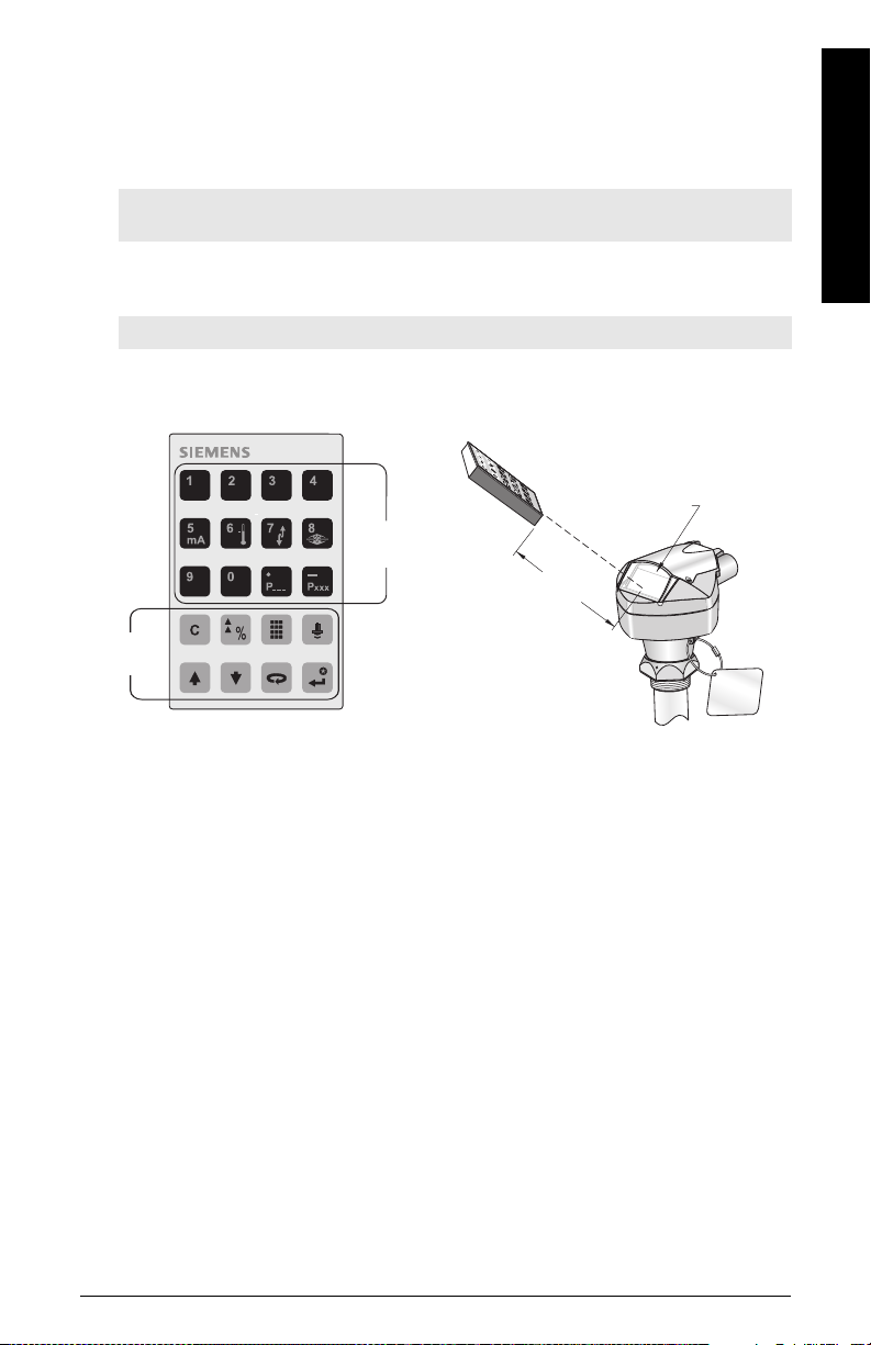
handheld programmer
Numeric and
Auxiliary keys
Function
Keys
max. 600 mm
(2 ft)
The Lock parameter, P000, secures SITRANS Probe LR against changes via the handheld
programmer. To enable programming, set P00 0 to the Unlocked Value stored in P069.
To disable programming, enter a different value.
Note:
• A remote master can still change configuration, if P799 is set to allow this.
Handheld programmer
Note: For detailed instructions on using the handheld programmer, see the next page.
For direct access to SITRANS Probe LR, point the handheld programmer at the display
from a maximum distance of 600 mm (2 ft), and press the keys.
Operation
7ML19985HR02 SITRANS Probe LR – INSTRUCTION MANUAL Page 21
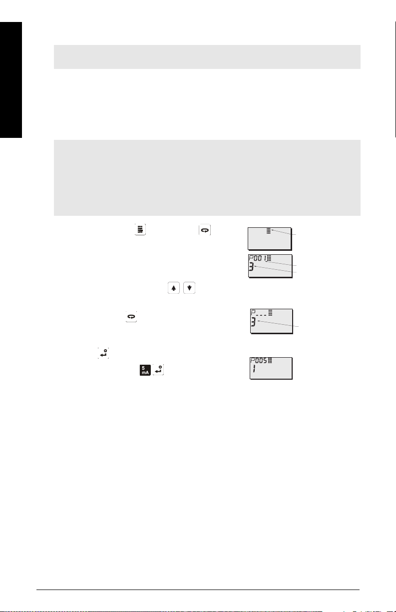
Activating SITRANS Probe LR
Param ete r Value
Parameter Number
PROGRAM Icon
current value
Note: Keep infrared devices such as laptops, cell phones, and PDAs, away from
SITRANS Probe LR to prevent inadvertent operation.
Power up the instrument. SITRANS Probe LR starts in RUN mode, and detects the
Operation
material level. It displays the material level (in meters) referenced from Empty (process
empty level). This is the default start-up mode.
Accessing a parameter
Notes:
• The following instructions apply when using the Handheld Programmer.
• Do not use the Handheld Programmer at the same time as SIMATIC PDM, or erratic
operation may result.
• You do not need to key in initial zeros when entering a parameter number: for
example, for P005, key in 5.
1. Press PROGRAM then DISPLAY , to
activate PROGRAM mode.
2. Either use the ARROW keys to scroll to a
different parameter, or:
3. Press DISPLAY
Number field.
4. Key in the desired parameter number followed by
ENTER .
For example: press
The LCD displays the new parameter number and
value.
to open the Parameter
.
Page 22 SITRANS Probe LR – INSTRUCTION MANUAL 7ML19985HR02

Changing a Parameter Value
Notes:
• Security must be disabled to enable programming: set P000 to the Unlocked Value
stored in P069.
• Invalid entries will be rejected or limited.
• CLEAR can be used to clear the field.
1. Use the ARROW keys to scroll to the parameter number, or press
DISPLAY
2. Key in the new value.
3. Press ENTER to set the value.
and key in the parameter number followed by ENTER .
Parameter Reset to Factory Default
1. Scroll to the parameter or enter its address.
2. Press CLEAR then ENTER . The value returns to the default setting.
P999 Master Reset
Note: Following a Master Reset, complete reprogramming is required.
Resets all parameters to their factory settings, with the following exceptions:
• P0 00 and P069 are not reset.
• P838 is not reset (the learned TVT curve is not lost).
1. Press PROGRAM , then DISPLAY to activate PROGRAM mode.
2. Press DISPLAY to open parameter fields.
3. Key in 999.
Press CLEAR then ENTER , to Clear All and
initiate reset. The LCD displays C.ALL.
Operation
4. Reset complete. (Reset takes several seconds
to complete.)
7ML19985HR02 SITRANS Probe LR – INSTRUCTION MANUAL Page 23

Using Units or Percent (%)
Many parameters can be viewed either as a percentage, or in measurement units (P005).
View the parameter, then press MODE to toggle between units and percentage.
Quick Setup for local operation (outline)
Operation
Set the Quick Start parameters between P001 and P010 (the main settings that apply to all
applications and make the system operational). Then set P837 and P838 to ignore false
echoes, and return to RUN mode.
1. Select a language option, or numeric, for the auxiliary reading (P010).
2. Select the measurement mode: level, space, or distance (P001).
3. Set the response time to level changes (P003).
4. Select units of measurement: m, cm, mm, ft, or in. (P005).
5. Set process empty level (Empty: P006).
6. Set the range to be measured (Span: P007).
7. To ignore false echoes before the material echo, set Auto False-Echo Suppression
Distance (P838).
8. Enable Auto False-Echo Suppression (P837).
9. Return to RUN mode.
Setup Instructions
Notes:
•In PROGRAM mode, you can use the ARROW keys to scroll to a
parameter number.
• The default parameter values are indicated by an asterisk (*) in the tables.
Using the handheld programmer, set each parameter value to suit your application. (For
detailed instructions on accessing a parameter and changing the value, see page 22.)
Page 24 SITRANS Probe LR – INSTRUCTION MANUAL 7ML19985HR02
 Loading...