

Siemens SITRANS P DS III, 7MF4.34 Series, 7MF4.33 Series, 7MF4.35 Series User Manual

SITRANS TANK LEVEL TRANSMITTER
MODELS: P DS III TANK
PRODUCT INSTRUCTION MANUAL V1.0
MAY 2016
201 SOUTH HOUSTON AVE.
TULSA, OK 74127
PHONE (918) 584-4700
WWW.ERNIEGRAVES.COM

English ······························································································· 3
Français ··························································································· 49
Deutsch ···························································································· 96
Español ··························································································· 142
Italiano ···························································································· 189
Nederlands ······················································································ 235
1

SITRANS
Pressure transmitter
SITRANS P DS III (7MF4.33.. 7MF4.34.. 7MF4.35..)
Compact Operating Instructions
Legal information
Warning notice system
DANGER
indicates that death or severe personal injury will result if proper precautions are not taken.
WARNING
indicates that death or severe personal injury may result if proper precautions are not taken.
CAUTION
indicates that minor personal injury can result if proper precautions are not taken.
NOTICE
indicates that property damage can result if proper precautions are not taken.
Qualified Personnel
personnel qualified
Proper use of Siemens products
WARNING
Siemens products may only be used for the applications described in the catalog and in the relevant technical documentation. If products
problems. The permissible ambient conditions must be complied with. The information in the relevant documentation must be observed.
1
Introduction
1.1
Purpose of this documentation
See also
This manual contains notices you have to observe in order to ensure your personal safety, as well as to prevent damage to property. The
notices referring to your personal safety are highlighted in the manual by a safety alert symbol, notices referring only to property damage
have no safety alert symbol. These notices shown below are graded according to the degree of danger.
If more than one degree of danger is present, the warning notice representing the highest degree of danger will be used. A notice warning of
injury to persons with a safety alert symbol may also include a warning relating to property damage.
The product/system described in this documentation may be operated only by
the relevant documentation, in particular its warning notices and safety instructions. Qualified personnel are those who, based on their
training and experience, are capable of identifying risks and avoiding potential hazards when working with these products/systems.
Note the following:
and components from other manufacturers are used, these must be recommended or approved by Siemens. Proper transport, storage,
installation, assembly, commissioning, operation and maintenance are required to ensure that the products operate safely and without any
These instructions are a brief summary of important features, functions and safety information, and contain all information
required for safe use of the device. It is your responsibility to read the instructions carefully prior to installation and
commissioning. In order to use the device correctly, first review its principle of operation.
The instructions are aimed at persons who mechanically assemble the device, connect it electrically, and start it up.
To achieve optimum usage of the device, read the detailed version of the manual.
for the specific task in accordance with
Instructions and manuals (http://www.siemens.com/processinstrumentation/documentation)
© Siemens AG 2013. All rights reserved
A5E03434626-03, 06/2013
3

1.2
History
Edition
Firmware identifier nameplate
System integration
Installation path for PDM
FF: FW: 11.01.01
1.3
Purpose
Overview
This history establishes the correlation between the current documentation and the valid firmware of the device.
The documentation of this edition applies to the following firmware:
06/2013 HART:
FW: 11.03.03, FW: 11.03.04,
FW: 11.03.05, FW: 11.03.06
PA: FW: 301.01.10
Depending on the version, a transmitter measures corrosive, non-corrosive and hazardous gases, vapors and liquids.
You can use the transmitter for the following types of measurement:
● Gauge pressure
● Absolute pressure
● Differential pressure
With appropriate parameter settings and the necessary add-on parts (e.g. flow orifices and remote seals), the pressure
transmitter can also be used for the following measurements:
● Level
● Volume
● Mass
● Volume of flow
● Mass flow rate
The output signal is always a load-independent direct current between 4 and 20 mA.
You can install the "intrinsically-safe" or "explosion-proof" version of the transmitter in hazardous areas. The devices have an
EC type examination certificate and comply with the appropriate harmonized European CENELEC directives.
Transmitters with remote seals of different shapes can be delivered for special applications. For example, measuring highviscosity substances is a special application.
Operate the device in accordance with the specifications in Section Technical specifications (Page 35).
For additional information, please refer to the operating instructions for the device.
SIMATIC PDM 8.x SITRANS P DSIII.2
SITRANS P DS III (7MF4.33.. 7MF4.34.. 7MF4.35..)
4 A5E03434626-03, 06/2013
1.4
Checking the consignment
WARNING
Using a damaged or incomplete device
● Do not use damaged or incomplete devices.
1.5
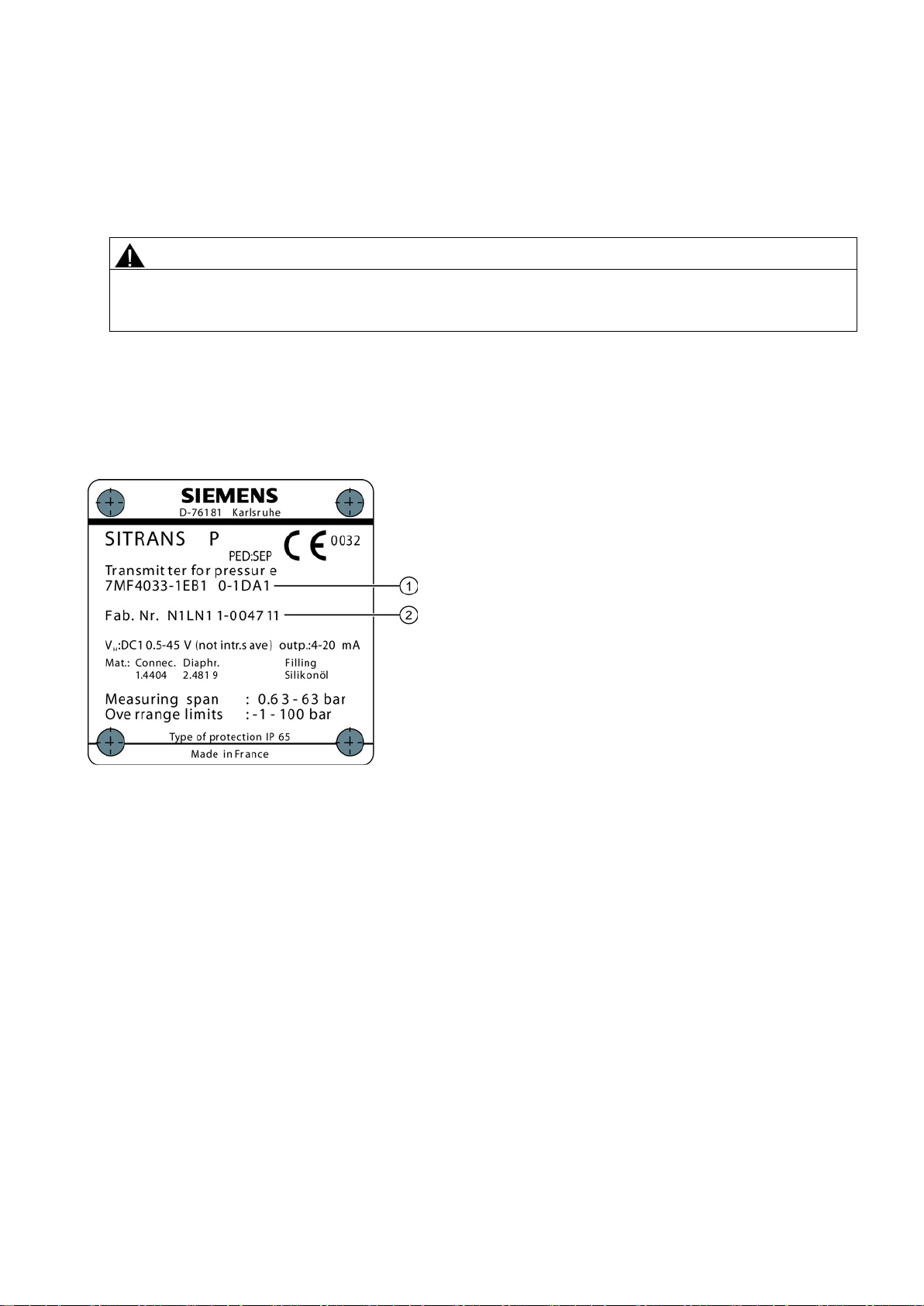
Nameplate layout
Nameplate with general information
①
Order number (machine-readable product code)
②
Serial number
1. Check the packaging and the device for visible damage caused by inappropriate handling during shipping.
2. Report any claims for damages immediately to the shipping company.
3. Retain damaged parts for clarification.
4. Check the scope of delivery by comparing your order to the shipping documents for correctness and completeness.
Danger of explosion in hazardous areas.
The nameplate bearing the Order No. and other important information, such as design details and technical data, is on the
side of the enclosure.
Figure 1-1 Example of a nameplate
SITRANS P DS III (7MF4.33.. 7MF4.34.. 7MF4.35..)
A5E03434626-03, 06/2013
5
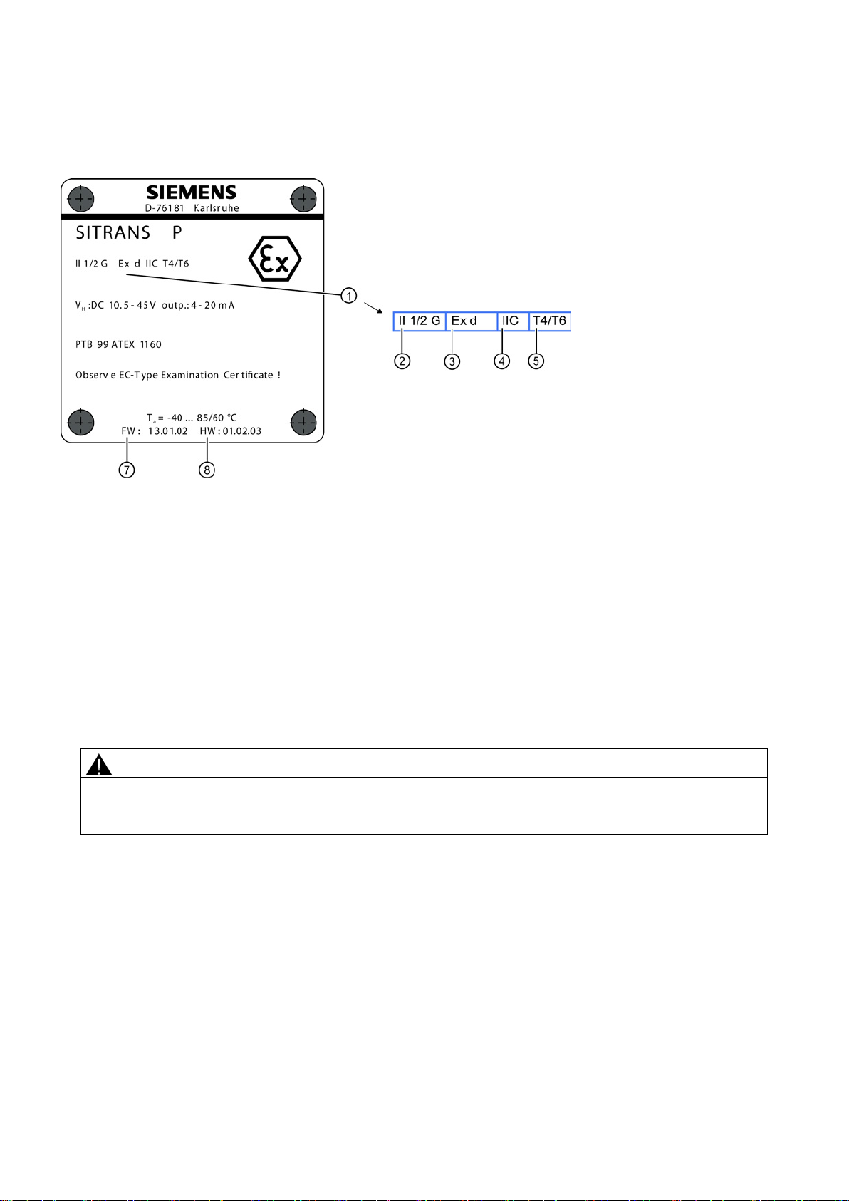
Nameplate with approval information
①
⑤
②
Category for operating area
⑥
Device protection level
③
Type of protection
⑦
Firmware identifier
④
Group (gas, dust)
⑧
Hardware identifier
1.6
Transportation and storage
CAUTION
Insufficient protection during storage
● Provide additional packaging as necessary.
1.7
Notes on warranty
On the opposite side is the nameplate with approval information. This nameplate shows e.g. the hardware and firmware
versions. You must also observe the information in the relevant certificate for a transmitter version for use in hazardous
areas.
Figure 1-2 Example of a nameplate
To guarantee sufficient protection during transport and storage, observe the following:
● Keep the original packaging for subsequent transportation.
● Devices/replacement parts should be returned in their original packaging.
● If the original packaging is no longer available, ensure that all shipments are properly packaged to provide sufficient
Special conditions for storage and transportation of the device are listed in "Technical data" (Page 35).
Characteristics for hazardous area
protection during transport. Siemens cannot assume liability for any costs associated with transportation damages.
The packaging only provides limited protection against moisture and infiltration.
Maximum surface temperature (temperature class)
The contents of this manual shall not become part of or modify any prior or existing agreement, commitment or legal
relationship. The sales contract contains all obligations on the part of Siemens as well as the complete and solely applicable
warranty conditions. Any statements regarding device versions described in the manual do not create new warranties or
modify the existing warranty.
The content reflects the technical status at the time of publishing. Siemens reserves the right to make technical changes in
the course of further development.
SITRANS P DS III (7MF4.33.. 7MF4.34.. 7MF4.35..)
6 A5E03434626-03, 06/2013

2
Safety instructions
2.1
Precondition for use
2.1.1
Warning symbols on the device
Symbol
Explanation
2.1.2
Laws and directives
2.1.3
Conformity with European directives
Electromagnetic Compatibility EMC
2004/108/EC
Directive of the European Parliament and of the Council on the approximation of the
laws of the Member States relating to elec
Directive 89/336/EEC.
Atmosphère explosible ATEX
94/9/EC
Directive of the European Parliament and the Council on the approximation of the
laws of the Member States concerning equipment and protective systems intend
for use in potentially explosive atmospheres.
Pressure Equipment Directive PED
97/23/EC
Directive of the European Parliament and of the Council on the approximation of the
laws of the Member States concerning pressure equipment.
2.2
Improper device modifications
WARNING
Improper device modifications
cancels the manufacturer's warranty and the product approvals.
2.3
Requirements for special applications
This device left the factory in good working condition. In order to maintain this status and to ensure safe operation of the
device, observe these instructions and all the specifications relevant to safety.
Observe the information and symbols on the device. Do not remove any information or symbols from the device. Always
keep the information and symbols in a completely legible state.
Observe the test certification, provisions and laws applicable in your country during connection, assembly and operation.
These include, for example:
● National Electrical Code (NEC - NFPA 70) (USA)
● Canadian Electrical Code (CEC) (Canada)
Further provisions for hazardous area applications are for example:
● IEC 60079-14 (international)
● EN 60079-14 (EC)
The CE mark on the device is a sign of conformity with the following European directives:
Consult operating instructions
tromagnetic compatibility and repealing
ed
The standards applied can be found in the EC declaration of conformity for the device.
Danger to personnel, system and environment can result from modifications to the device, particularly in hazardous areas.
● Only carry out modifications that are described in the instructions for the device. Failure to observe this requirement
Due to the large number of possible applications, each detail of the described device versions for each possible scenario
during commissioning, operation, maintenance or operation in systems cannot be considered in the instructions. If you need
additional information not covered by these instructions, contact your local Siemens office or company representative.
SITRANS P DS III (7MF4.33.. 7MF4.34.. 7MF4.35..)
A5E03434626-03, 06/2013
7

Note
Operation under special ambient conditions
We highly recommend that you contact your Siemens representative or our application department
device under special ambient conditions as can be encountered in nuclear power plants or when the device is used for
research and development purposes.
2.4
Use in hazardous areas
Qualified personnel for hazardous area applications
WARNING
Unsuitable device for the hazardous area
● Only use equipment that is approved for use in the intended hazardous area and labelled accordingly.
See also
WARNING
Loss of safety of device with type of protection "Intrinsic safety Ex i"
● Observe the specifications for the electrical data on the certificate and in Chapter "Technical data (Page 35)".
WARNING
Use of incorrect device parts in potentially explosive environments
● Do not swap device parts unless the manufacturer specifically ensures compatibility of these parts.
WARNING
Risk of explosion due to electrostatic charge
before you operate the
Persons who install, assemble, commission, operate and service the device in a hazardous area must have the following
specific qualifications:
● They are authorized, trained or instructed in operating and maintaining devices and systems according to the safety
regulations for electrical circuits, high pressures, aggressive and hazardous media.
● They are authorized, trained, or instructed in carrying out work on electrical circuits for hazardous systems.
● They are trained or instructed in maintenance and use of appropriate safety equipment according to the pertinent safety
regulations.
Danger of explosion.
Technical specifications (Page 35)
If the device has already been operated in non-intrinsically safe circuits or the electrical specifications have not been
observed, the safety of the device is no longer ensured for use in hazardous areas. There is a danger of explosion.
● Connect the device with type of protection "Intrinsic safety" solely to an intrinsically safe circuit.
Devices and their associated device parts are either approved for different types of protection or they do not have
explosion protection. There is a danger of explosion if device parts (such as covers) are used for devices with explosion
protection that are not expressly suited for this type of protection. If you do not adhere to these guidelines, the test
certificates and the manufacturer warranty will become null and void.
● Use only device parts that have been approved for the respective type of protection in the potentially explosive
environment. Covers that are not suited for the "explosion-proof" type of protection are identified as such by a notice
label attached to the inside of the cover with "Not Ex d Not SIL".
To prevent the build-up of an electrostatic charge in a hazardous area, the key cover must be closed during operation and
the screws tightened.
The key cover may be opened temporarily at any time for the purposes of operating the transmitter, even during plant
operation; the screws should then be tightened again.
SITRANS P DS III (7MF4.33.. 7MF4.34.. 7MF4.35..)
8 A5E03434626-03, 06/2013
3
Installing/mounting
3.1
Basic safety instructions
WARNING
Wetted parts unsuitable for the process media
information in "Technical data" (Page 35).
WARNING
Incorrect material for the diaphragm in Zone 0
section "Technical specifications (Page 35)".
WARNING
Unsuitable connecting parts
● Ensure that connecting parts (such as flange gaskets and bolts) are suitable for connection and process media.
Note
Material compatibility
Siemens can provide you with support concerning selection of sensor components wetted by process media. However, you
are responsible for the selection of components. Siemens accepts no liability for faults or failures resulting from incompatible
materials.
WARNING
Exceeded maximum permissible operating pressure
The maximum permissible operating pressure depends on the device version. The device can be damaged if the operating
information on the nameplate and/or in "Technical specifications (Page 35)".
WARNING
Exceeded maximum ambient or process media temperature
Refer to the information in Chapter "Technical specifications (Page 35)".
Danger of injury or damage to device.
Hot, toxic and corrosive media could be released if the process medium is unsuitable for the wetted parts.
● Ensure that the material of the device parts wetted by the process medium is suitable for the medium. Refer to the
Danger of explosion in the hazardous area. In the case of operation with intrinsically safe supply units of category "ib" or
devices of the flameproof enclosure version "Ex d" and simultaneous use in Zone 0, transmitter explosion protection
depends on the tightness of the diaphragm.
● Ensure that the material used for the diaphragm is suitable for the process medium. Refer to the information in the
Danger of injury or poisoning.
In case of improper mounting hot, toxic and corrosive process media could be released at the connections.
Danger of injury or poisoning.
pressure is exceeded. Hot, toxic and corrosive process media could be released.
● Make sure that the device is suitable for the maximum permissible operating pressure of your system. Refer to the
Danger of explosion in hazardous areas.
Device damage.
● Make sure that the maximum permissible ambient and process media temperatures of the device are not exceeded.
SITRANS P DS III (7MF4.33.. 7MF4.34.. 7MF4.35..)
A5E03434626-03, 06/2013
9
WARNING
Open cable inlet or incorrect cable gland
type of protection.
WARNING
Incorrect conduit system
regulations and the requirements stated in the relevant approvals.
See also
WARNING
Incorrect mounting at Zone 0
● Observe the standard IEC/EN 60079-14.
WARNING
Danger with "flameproof enclosure" protection
● Ensure that there is a space of at least 40 mm between the flameproof joint and the fixed parts.
①
Flameproof joint
WARNING
Loss of explosion protection
● Close the device as described in Chapter "Connecting the device (Page 21)".
Danger of explosion in hazardous areas.
● Close the cable inlets for the electrical connections. Only use cable glands or plugs which are approved for the relevant
Danger of explosion in hazardous areas as result of open cable inlet or incorrect conduit system.
● In the case of a conduit system, mount a spark barrier at a defined distance from the device input. Observe national
Technical specifications (Page 35)
Danger of explosion in hazardous areas.
● Ensure sufficient tightness at the process connection.
Danger of explosion in hazardous areas. An explosion may be caused by hot gas escaping from the flameproof enclosure
if there is too little space between it and the fixed parts.
Danger of explosion in hazardous areas if the device is open or not properly closed.
SITRANS P DS III (7MF4.33.. 7MF4.34.. 7MF4.35..)
10 A5E03434626-03, 06/2013
CAUTION
Hot surfaces resulting from hot process media
Refer to the information in Chapter "Technical specifications (Page 35)".
CAUTION
External stresses and loads
● Prevent severe external stresses and loads from acting on the device.
3.1.1
Installation location requirements
WARNING
Insufficient air supply
specifications (Page 35)".
CAUTION
Aggressive atmospheres
● Ensure that the device is suitable for the application.
NOTICE
Direct sunlight
3.1.2
Proper mounting
NOTICE
Incorrect mounting
example installation torques requirements.
Danger of burns resulting from surface temperatures above 70 °C (155 °F).
● Take appropriate protective measures, for example contact protection.
● Make sure that protective measures do not cause the maximum permissible ambient temperature to be exceeded.
Damage to device by severe external stresses and loads (e.g. thermal expansion or pipe tension). Process media can be
released.
The device may overheat if there is an insufficient supply of air.
● Install the device so that there is sufficient air supply in the room.
● Observe the maximum permissible ambient temperature. Refer to the information in the section "Technical
Damage to device through penetration of aggressive vapors.
Increased measuring errors.
● Protect the device from direct sunlight.
Make sure that the maximum ambient temperature is not exceeded. Refer to the information in the section Technical
specifications (Page 35).
The device can be damaged, destroyed, or its functionality impaired through improper mounting.
● Before installing ensure there is no visible damage to the device.
● Make sure that process connectors are clean, and suitable gaskets and glands are used.
● Mount the device using suitable tools. Refer to the information in Chapter "Technical specifications (Page 35)", for
SITRANS P DS III (7MF4.33.. 7MF4.34.. 7MF4.35..)
A5E03434626-03, 06/2013
11

Note
Loss of degree of protection
Damage to device if the enclosure is open or not properly closed. The degree of protection specified on the nameplate or in
"Technical data"
● Make sure that the device is securely closed.
See also
3.2
Disassembly
WARNING
Incorrect disassembly
● Secure the remaining connections so that no damage can result if the process is started unintentionally.
3.3
Installation (except level)
3.3.1
Instructions for installation (except level)
Conditions
Note
Compare the desired operating data with the data on the nameplate.
Please also refer to the information on the remote seal if this
Note
Protect the transmitter against:
●
●
●
●
● Direct sunlight
Installation configuration
(Page 35) is no longer guaranteed.
Connecting the device (Page 21)
The following dangers may result through incorrect disassembly:
- Injury through electric shock
- Danger through emerging media when connected to the process
- Danger of explosion in hazardous area
In order to disassemble correctly, observe the following:
● Before starting work, make sure that you have switched off all physical variables such as pressure, temperature,
electricity etc. or that they have a harmless value.
● If the device contains dangerous media, it must be emptied prior to disassembly. Make sure that no environmentally
hazardous media are released.
The installation location is to be as follows:
● Easily accessible
● As close as possible to the measuring point
● Vibration-free
● Within the permitted ambient temperature values
Direct heat radiation
Rapid temperature fluctuations
Heavy contamination
Mechanical damage
is fitted.
The transmitter may in principle be configured above or below the pressure tapping point. The recommended configuration
depends on the aggregate state of the medium.
SITRANS P DS III (7MF4.33.. 7MF4.34.. 7MF4.35..)
12 A5E03434626-03, 06/2013

Installation configuration for gases
Installation configuration for vapor and liquid
3.3.2
Installation (except level)
Note
Damage to measuring cell
When installing the process connection of the pressure transmitter, do not rotate the housing. Rotating t
damage the measuring cell.
To avoid damage to the device, tighten the threaded nuts of the measuring cell using a wrench.
Procedure
See also
3.3.3
Fastening
Fastening without the mounting bracket
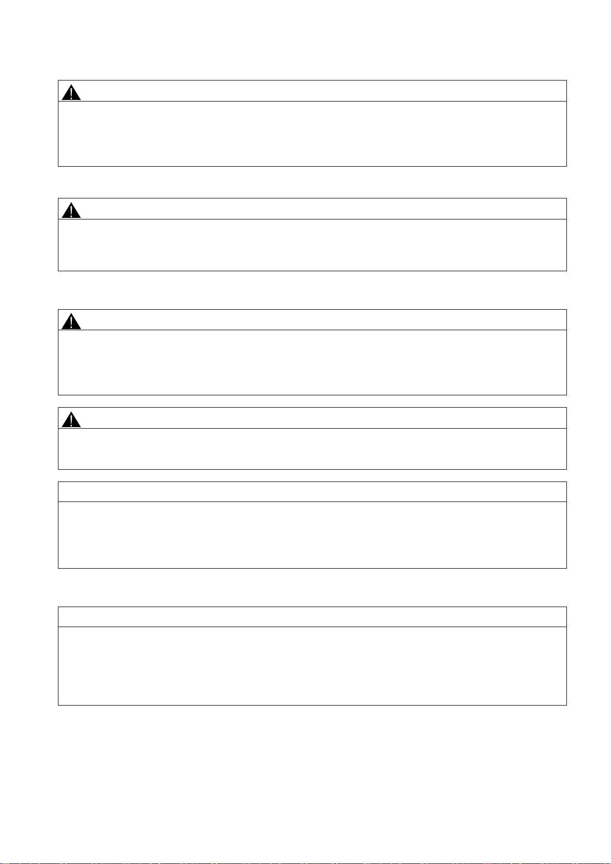
Fastening with the mounting bracket
Install the transmitter above the pressure tapping point.
Lay the pressure tubing with a constant gradient to the pressure tapping point, so that any condensation produced can drain
in the main line and thereby avoid corruption of the measured values.
Install the transmitter below the pressure tapping point.
Lay the pressure tubing with a constant gradient to the pressure tapping point so that any gas pockets can escape in the
main line.
Attach the transmitter to the process connection with an appropriate tool.
Introduction to commissioning (Page 24)
You can fasten the transmitter directly on the process connection.
You can fasten the mounting bracket as follows:
● On a wall or a mounting frame using two screws
● On a vertical or horizontal mounting tube (Ø 50 to 60 mm) using a tube bracket
Fasten the transmitter mounting bracket using the two screws provided.
he housing may
SITRANS P DS III (7MF4.33.. 7MF4.34.. 7MF4.35..)
A5E03434626-03, 06/2013
13
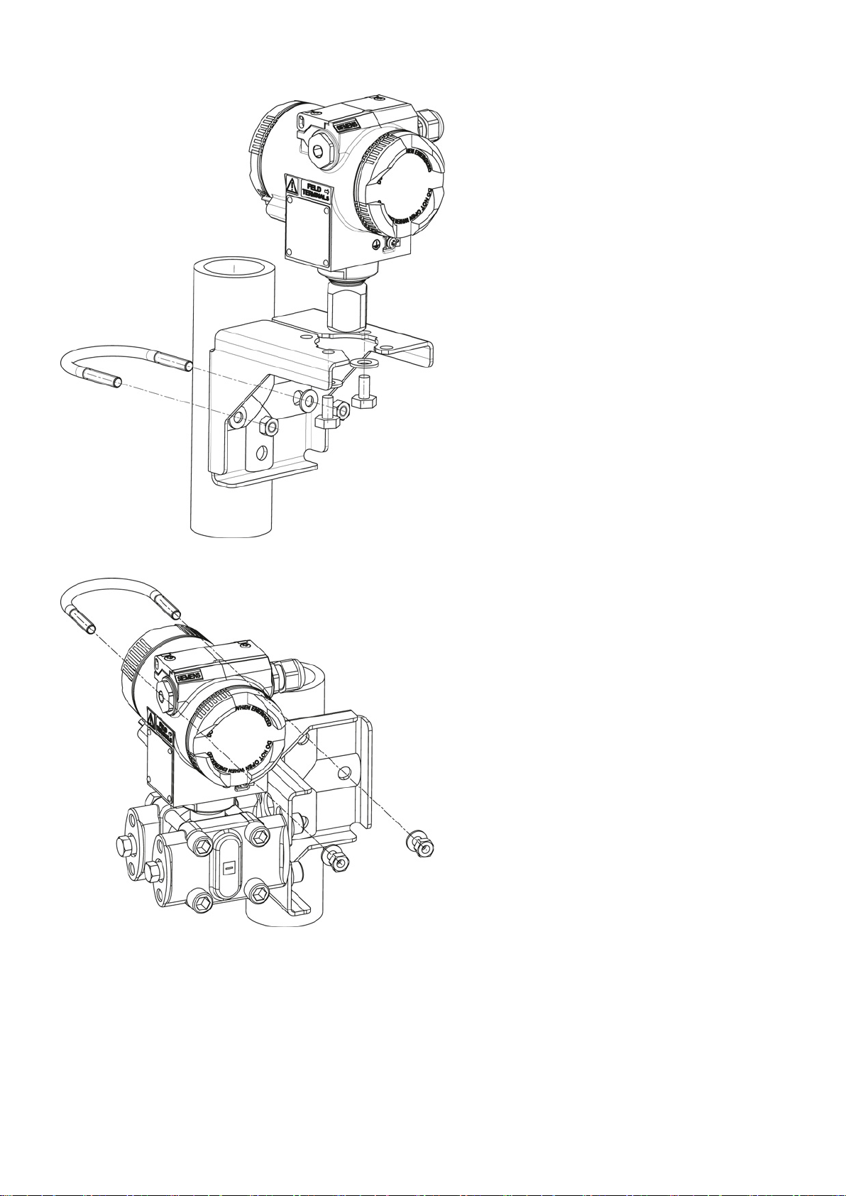
Figure 3-1 Fastening the transmitter on the mounting bracket
Figure 3-2 An example of fastening the transmitter on the mounting bracket in the case of differential pressure and
horizontal differential pressure lines
SITRANS P DS III (7MF4.33.. 7MF4.34.. 7MF4.35..)
14 A5E03434626-03, 06/2013
3.4
"Level" installation
3.4.1
Instructions for level installation
Requirements
Note
Compare the desired
Please also refer to the information on the remote seal if this is fitted.
Note
Protect the transmitter from:
●
●
●
●
● Direct sunlight
Note
Select the height of the mounting flange such that the pressure transmitter is always mounted below the lowest fill height to
be measured.
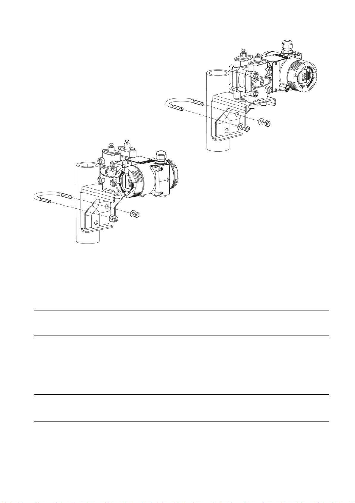
Figure 3-3 An example of fastening on the mounting bracket in the case of differential pressure and vertical differential
pressure lines
Direct heat
Rapid temperature changes
Severe soiling
Mechanical damage
operating data with the data on the nameplate.
The installation location is to be as follows:
● Easily accessible
SITRANS P DS III (7MF4.33.. 7MF4.34.. 7MF4.35..)
A5E03434626-03, 06/2013
15
3.4.2
Installation for level
Note
Seals are required for the installation. The seals must be compatible with the medium to be measured.
Seals are not included in the delivery.
Procedure
3.4.3
Connection of the negative pressure line
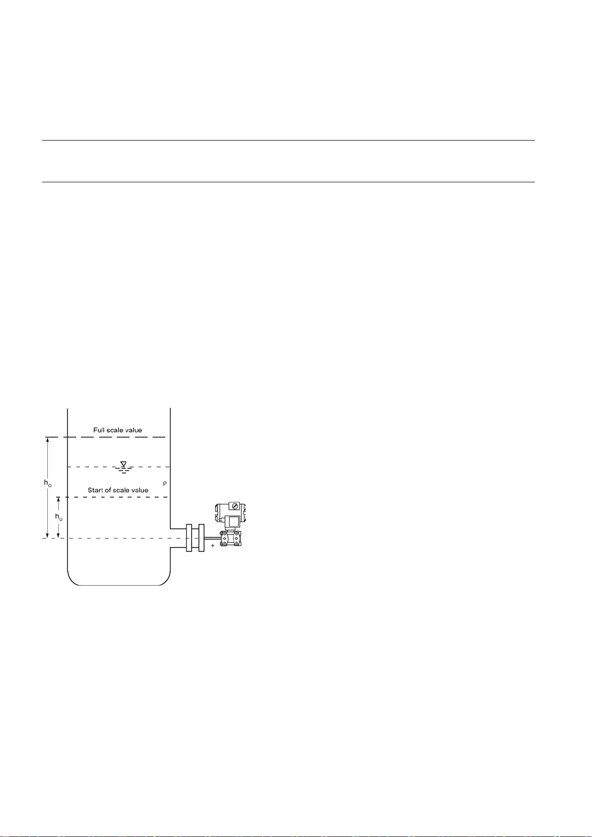
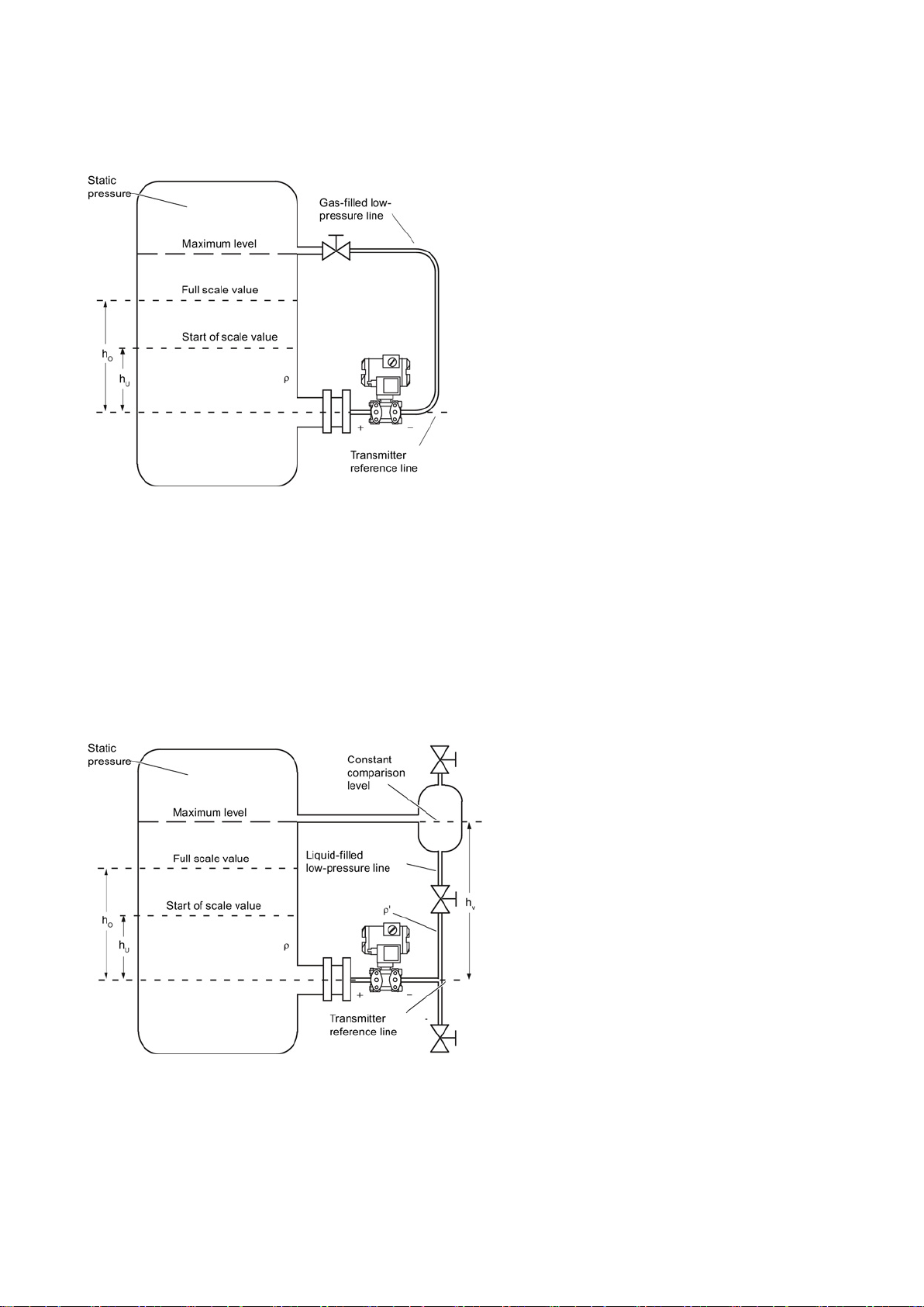
Assembly on an open container
Measurement assembly on an open container
Formula:
Start of scale value: p
Full
hU
Lower filling level
ΔpMA
Start of scale value
hO
Upper filling level
ΔpME
Full-scale value
p
Pressure
ρ
Density of the measured medium in the container
g
Acceleration due to gravity
● The measuring point must be as close as possible
● Vibration-free
● Within the permitted ambient temperature values
To install the transmitter for level, proceed as follows:
1. Attach the seal to the container's mating flange.
2. Screw on the transmitter's flange.
3. Observe the installation position.
A line is not required when taking measurements in an open container since the negative chamber is connected with the
atmosphere.
Ensure that no dirt enters the open connection ports, for example by using connection screws with a 7MF4997-1CP bleed
valve.
Ensure that the seal is centrically positioned and that it does not restrict the movement of the flange's seal diaphragm in
any way as otherwise the tightness of the process connection is not guaranteed.
-scale value: p
= ρ · g · hU
MA
= ρ · g · hO
ME
SITRANS P DS III (7MF4.33.. 7MF4.34.. 7MF4.35..)
16 A5E03434626-03, 06/2013
Assembly on a closed container
Measurement assembly on a closed container (no or little
condensate separation)
Formula:
Start
Full
hU
Lower filling level
ΔpMA
Start of scale value
hO
Upper filling level
ΔpME
Full-scale value
p
Pressure
ρ
Density of the measured medium in the container
g
Acceleration due to gravity
Measurement assembly on a closed container (strong condensate
formation)
Formula:
Start
Δp
Full
Δp
hU
Lower filling level
ΔpMA
Start of scale value
When taking measurements in a closed container without or with little condensate formation, the negative pressure line is
not filled. Lay the line in such a way that pockets of condensate do not form. Install a condensation container if required.
-of-scale value: ΔpMA = ρ · g · hU
-scale value: ΔpME = ρ · g · hO
When taking measurements in a closed container with strong condensate formation, you must fill the negative pressure line
(mostly with the condensate of the measured medium) and install a condensate pot. You can cut off the device using the
dual pneumatic block 7MF9001-2.
-of-scale value:
= g · (hU · ρ- hV · ρ')
MA
-scale value:
= g · (hO · ρ- hV · ρ')
MA
SITRANS P DS III (7MF4.33.. 7MF4.34.. 7MF4.35..)
A5E03434626-03, 06/2013
17
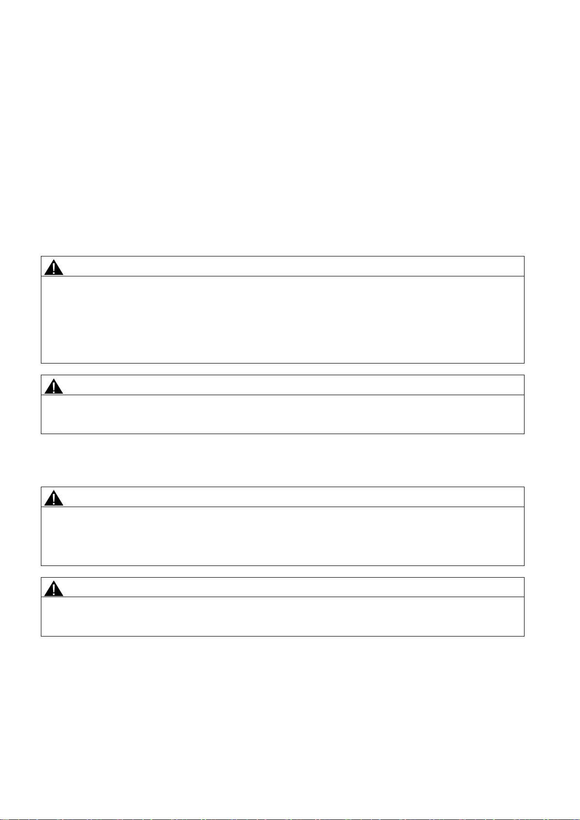
hO
Upper filling level
ΔpME
Full-scale value
hV
Gland distance
ρ
Density of the measured medium in the container
p Pressure
ρ ' Density of fluid in the
corresponds to the prevailing temperature there
g
Acceleration due to gravity
4
Connecting
4.1
Basic safety instructions
WARNING
Unsuitable cables and/or cable glands
● After installation check that the cables are seated firmly.
WARNING
Hazardous contact voltage in versions with 4-conductor extension
● Observe the instructions in the 4-conductor extension operating manual for the electrical connection.
See also
WARNING
Improper power supply
be found in the certificates, in Chapter "Technical specifications (Page 35)" or on the nameplate.
WARNING
Unsafe extra-low voltage
● Connect the device to an extra-low voltage with safe isolation (SELV).
The process connection on the negative side is a female thread 1/4-18 NPT or an oval flange.
Lay the line for the negative pressure using a seamless steel tube 12 mm x 1.5 mm.
Danger of explosion in hazardous areas.
● Only use suitable cables and cable glands complying with the requirements specified in Chapter "Technical data
(Page 35)".
● Tighten the cable glands in accordance with the torques specified in Chapter "Technical data (Page 35)".
● When replacing cable glands use only cable glands of the same type.
negative pressure line
Danger of electrocution in case of incorrect connection.
Technical specifications (Page 35)
Danger of explosion in hazardous areas as result of incorrect power supply, e.g. using direct current instead of alternating
current.
● Connect the device in accordance with the specified power supply and signal circuits. The relevant specifications can
Danger of explosion in hazardous areas due to voltage flashover.
SITRANS P DS III (7MF4.33.. 7MF4.34.. 7MF4.35..)
18 A5E03434626-03, 06/2013
WARNING
Lack of equipotential bonding
Exception
WARNING
Unprotected cable ends
● Protect unused cable ends in accordance with IEC/EN 60079-14.
WARNING
Improper laying of shielded cables
● If grounding is required at both ends, use an equipotential bonding conductor.
WARNING
Connecting device in energized state
Exceptions
● Exceptions for type of protection "Non-sparking nA" (Zone 2) are regulated in the relevant certificate
WARNING
Incorrect selection of type of protection
unrecognizable on the nameplate.
NOTICE
Ambient temperature too high
°C (68 °F) higher.
NOTICE
Incorrect measured values with incorrect grounding
● If necessary, ground the device using the "-" connection.
Danger of explosion through compensating currents or ignition currents through lack of equipotential bonding.
● Ensure that the device is potentially equalized.
: It may be permissible to omit connection of the equipotential bonding for devices with type of protection
"Intrinsic safety Ex i".
Danger of explosion through unprotected cable ends in hazardous areas.
Danger of explosion through compensating currents between hazardous area and the non-hazardous area.
● Only ground shielded cables that run into the hazardous area at one end.
Danger of explosion in hazardous areas.
● Connect devices in hazardous areas only in a de-energized state.
:
● Circuits of limited energy may also be connected in the energized state in hazardous areas.
Danger of explosion in areas subject to explosion hazard.
This device is approved for several types of protection.
1. Decide in favor of one type of protection.
2. Connect the device in accordance with the selected type of protection.
3. In order to avoid incorrect use at a later point, make the types of protection that are not used permanently
Damage to cable sheath.
● At an ambient temperature ≥ 60 °C (140 °F), use heat-resistant cables suitable for an ambient temperature at least 20
The device must not be grounded via the "+" connection. It may otherwise malfunction and be permanently damaged.
SITRANS P DS III (7MF4.33.. 7MF4.34.. 7MF4.35..)
A5E03434626-03, 06/2013
19

Note
Electromagnetic compatibility (EMC)
You can use this device in industrial environments, households and small businesses.
For metal
protection can be increased by grounding the housing, see Chapter "
Note
Improvement of interference immunity
●
●
●
●
● Refer to HART communication information in Chapter "Technical specifications (Page 35)".
housings there is an increased electromagnetic compatibility compared to high-frequency radiation. This
Connecting the device (Page 21)".
Lay signal cables separate from cables with voltages > 60 V.
Use cables with twisted wires.
Keep device and cables in distance to strong electromagnetic fields.
Use shielded cables to guarantee the full specification according to HART.
SITRANS P DS III (7MF4.33.. 7MF4.34.. 7MF4.35..)
20 A5E03434626-03, 06/2013
4.2
Connecting the device
Opening the device
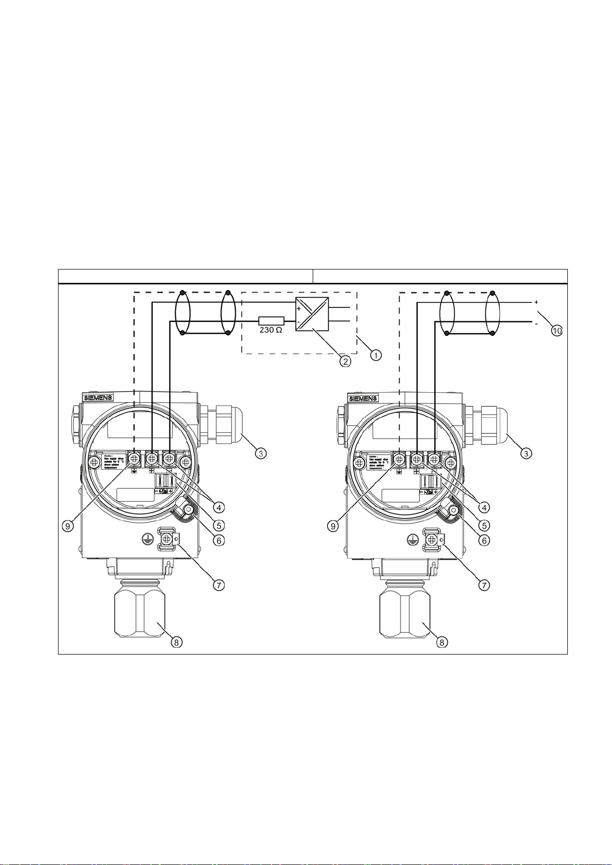
Connecting the device
HART
PROFIBUS PA / Foundation™ Fieldbus FF
①
Feed separator with integrated load
⑥
Safety catch
②
Auxiliary power
⑦
Protective conductor connection/
equipotential bonding terminal
③
Cable entry for auxiliary power/analog output
⑧
Process connection
④
Connecting terminals
⑨
Ground terminal
⑤
Test connector for direct current measuring device or
connection for external display
⑩
PROFIBUS PA / Foundation™ Fieldbus FF
1. Unscrew the cover of the electrical cable compartment. An identification text "FIELD TERMINAL" is provided at the side
of the housing.
1. Lead the connecting cable through the cable gland ③.
2. Connect the device to the plant with the protective conductor connection ⑦.
3. Connect the wires to the connecting terminals
Ensure the correct polarity! If necessary, ground the device using the "-" connection by connecting the "-" connection to
the ground terminal ⑨.
4. If necessary, connect the shield to the screw of the ground terminal
protective conductor connection.
④ "+" and "-".
⑨. This is electrically connected with the external
SITRANS P DS III (7MF4.33.. 7MF4.34.. 7MF4.35..)
A5E03434626-03, 06/2013
21

Electrical connection, power supply
SITRANS P DS III (7MF4.33.. 7MF4.34.. 7MF4.35..)
22 A5E03434626-03, 06/2013
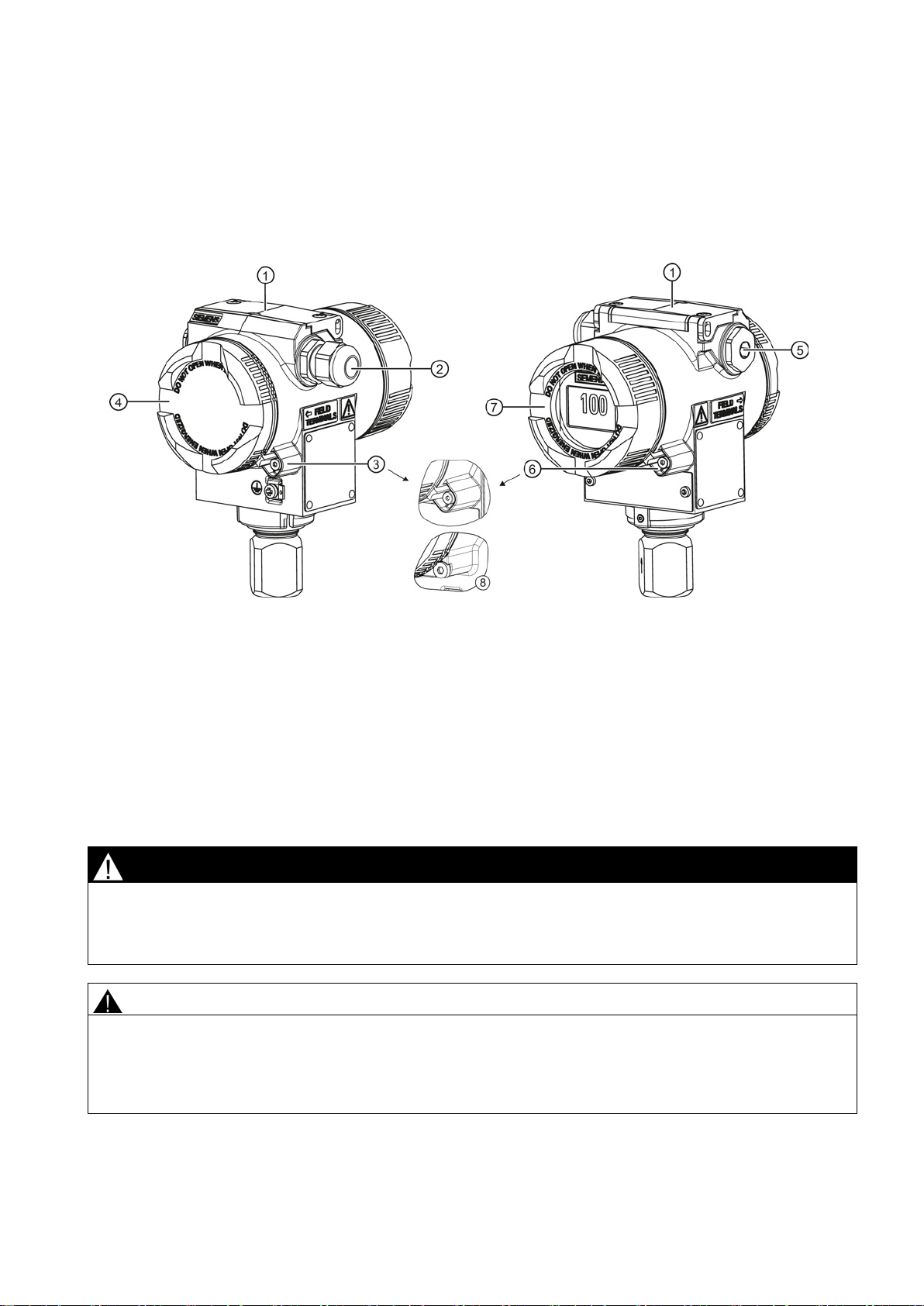
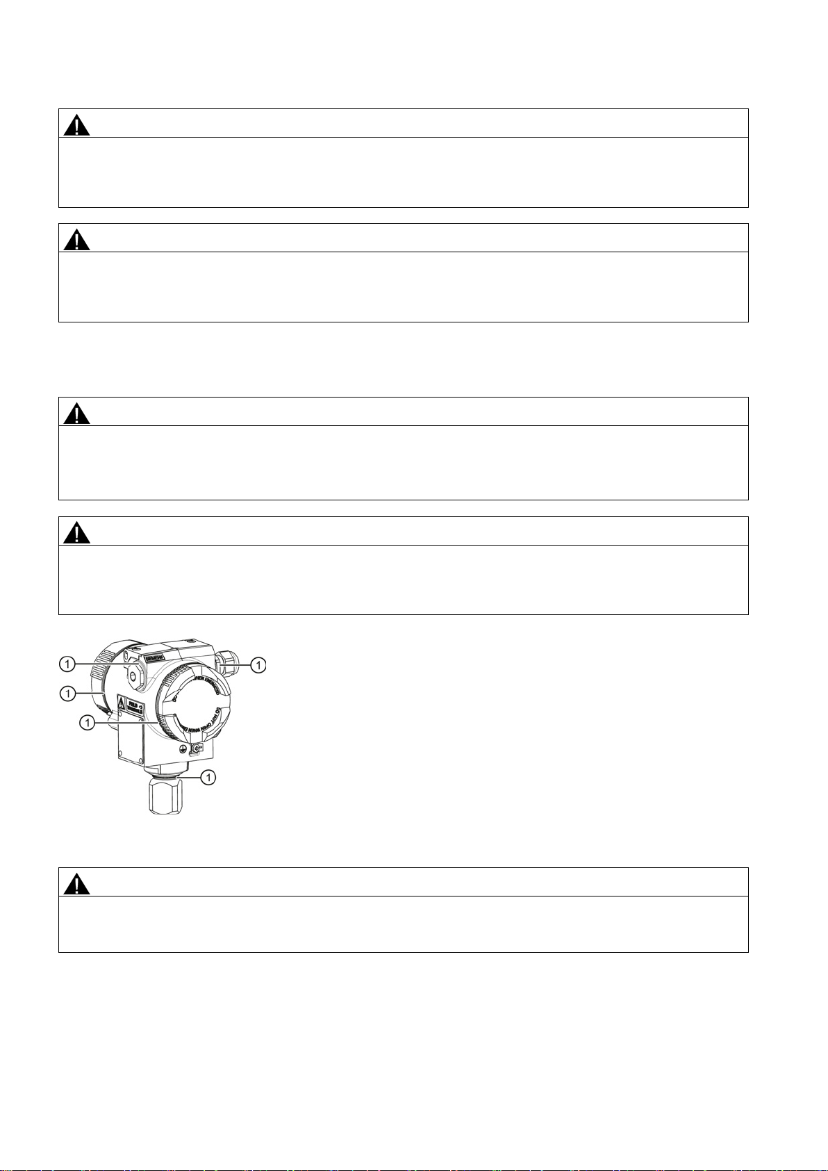
Closing the device
①
Key cover
⑤
Blanking plug
②
Cable gland
⑥
Safety catch (front)
③
Safety catch (back)
⑦
Cover (front), optionally with inspection window
④
Cover (rear) for electrical terminal compartment
⑧
Safety catch for stainless steel enclosure
5
Commissioning
5.1
Basic safety instructions
DANGER
Toxic gases and liquids
● Before venting ensure that there are no toxic gases and liquids in the device. Take the appropriate safety measures.
WARNING
Improper commissioning in hazardous areas
● Before commissioning take the effect on other devices in the system into account.
1. Screw the covers ④⑦ back on as far as they will go.
2. Secure each cover with the cover catch
3. Close the key cover
4. Tighten the screws in the key cover.
5. Check the tightness of the blanking plugs ⑤ and cable gland ② in accordance with the degree of protection.
①.
③⑥.
Figure 4-1 View of the transmitter: Left: Back right: Front view
Danger of poisoning when the device is vented.
If toxic process media are measured, toxic gases and liquids can be released when the device is vented.
Device failure or danger of explosion in hazardous areas.
● Do not commission the device until it has been mounted completely and connected in accordance with the information
in Chapter "Technical specifications (Page 35)".
SITRANS P DS III (7MF4.33.. 7MF4.34.. 7MF4.35..)
A5E03434626-03, 06/2013
23

WARNING
Opening device in energized state
Exception
Note
Hot surfaces
Hot process medium and high ambient temperatures lead to hot surfaces which can cause burns.
● Take corresponding protective measures, for example wear protective gloves.
5.2
Introduction to commissioning
Danger of explosion in areas subject to explosion hazard.
● Only open the device in a de-energized state.
● Check prior to commissioning that the cover, cover locks, and cable inlets are assembled in accordance with the
directives.
: Devices having the type of protection "Intrinsic safety Ex i" may also be opened in energized state in hazardous
areas.
Following commissioning, the transmitter is immediately ready for use.
To obtain stable measured values, the transmitter needs to be allowed to warm up for five minutes or so after the power
supply is switched on. Upon switch-on, the transmitter goes through an initialization routine (display at the end: "Init done").
If the transmitter initialization routine does not complete, check the auxiliary power.
The operating data must correspond to the values specified on the nameplate. If you switch on the auxiliary power, the
transmitter will operate.
The following commissioning cases are typical examples. Configurations different from those listed here may be meaningful
depending on the system configuration.
SITRANS P DS III (7MF4.33.. 7MF4.34.. 7MF4.35..)
24 A5E03434626-03, 06/2013
5.3
gauge pressure, absolute pressure from the differential pressure series and absolute pressure from the gauge pressure series
5.3.1
Commissioning for gases
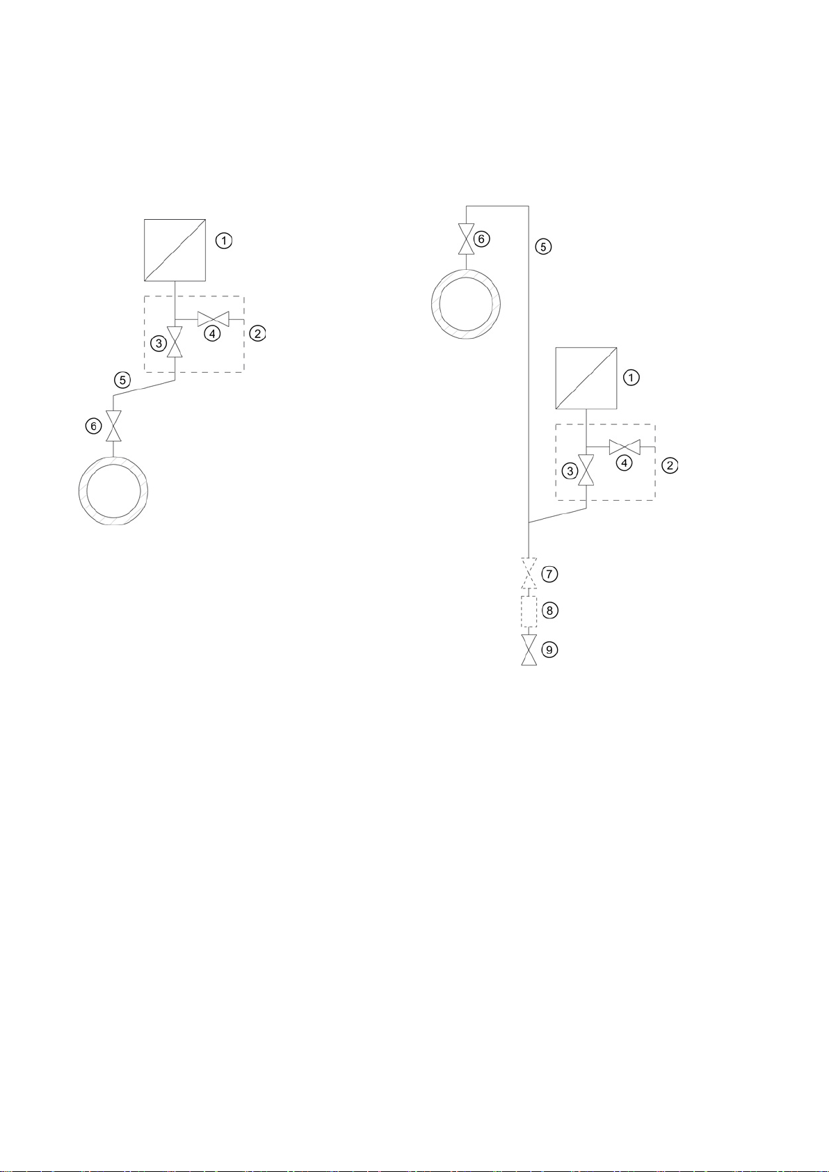
Usual arrangement
Special arrangement
Measuring gases above the pressure tapping point
Measuring gases below the pressure tapping point
①
Pressure transmitter
⑤
Pressure line
②
Shut
⑥
Shut
③
Shut
⑦
Shut
④
Shut
⑧
Condensate vessel (optional)
⑨
Drain valve
Condition
Procedure
①.
-off valve
-off valve (optional)
④.
-off module
All valves are closed.
To commission the transmitter for gases, proceed as follows:
1. Open the shut-off valve for the test connection
2. Via the test connection of the shut-off fitting ②, apply the pressure corresponding to the start of scale value to the
pressure transmitter
3. Check the start of scale value.
SITRANS P DS III (7MF4.33.. 7MF4.34.. 7MF4.35..)
A5E03434626-03, 06/2013
-off valve to process
-off valve for test connection or for bleed screw
25
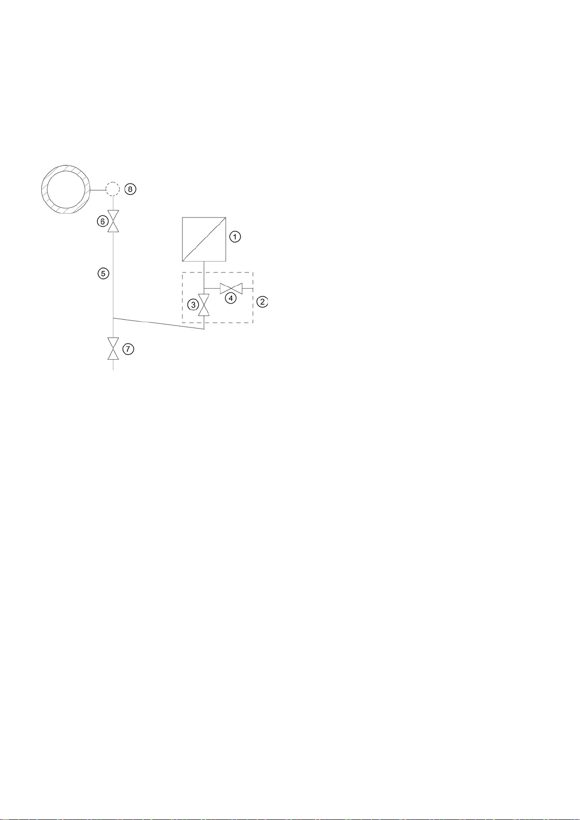
5.3.2
Commissioning with steam or liquid
①
Pressure transmitter
②
Shut-off fitting
③
Shut-off valve to process
④
Shut-off valve for test connection or for bleed screw
⑤
Pressure line
⑥
Shut-off valve
⑦
Blow-out valve
⑧
Compensation vessel (steam only)
Requirement
Procedure
4. If the start of scale value differs from the value desired, correct it.
5. Close the shut-off valve for the test connection
6. Open the shut-off valve
7. Open the shut-off valve for the process
⑥ at the pressure tapping point.
③.
④.
Figure 5-1 Measuring steam
All valves are closed.
To commission the transmitter for steam or liquid, proceed as follows:
1. Open the shut-off valve for the test connection
2. Via the test connection of the shut-off module ②, apply the pressure corresponding to the start of scale value to the
pressure transmitter
3. Check the start of scale value.
4. If the start of scale value differs from the value desired, correct it.
5. Close the shut-off valve for the test connection
6. Open the shut-off valve
7. Open the shut-off valve for the process
SITRANS P DS III (7MF4.33.. 7MF4.34.. 7MF4.35..)
①.
⑥ at the pressure tapping point.
④.
④.
③.
26 A5E03434626-03, 06/2013
5.4
Differential pressure and flow rate
5.4.1
Safety notes for commissioning with differential pressure and flow rate
WARNING
Incorrect or improper operation
Measure
● Ensure that the valves are operated correctly and properly.
5.4.2
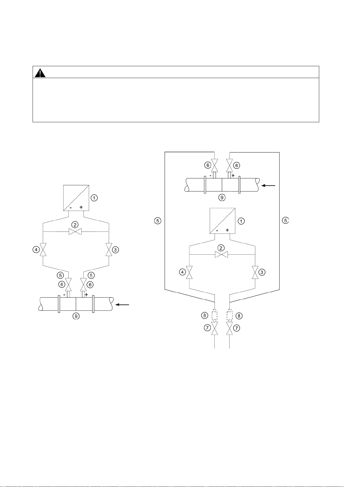
Commissioning in gaseous environments
Usual arrangement
Special arrangement
①
Pressure transmitter
⑥
Shut
②
Stabilizing valve
⑦
Drain valves
③, ④
Differential pressure valves
⑧
Condensate vessels
⑤
Differential pressure lines
⑨
Differential pressure transducer
Transmitter above
transducer
Transmitter below
differential pressure transducer
Condition
If the lock screws are missing or are not sufficiently tight, and/or if the valves are operated incorrectly or improperly, it could
lead to serious physical injuries or considerable damage to property.
● Make sure the locking screw and/or the vent valve are screwed in and tightened.
All shut-off valves are closed.
SITRANS P DS III (7MF4.33.. 7MF4.34.. 7MF4.35..)
A5E03434626-03, 06/2013
the differential pressure
-off valves
(optional)
the
27
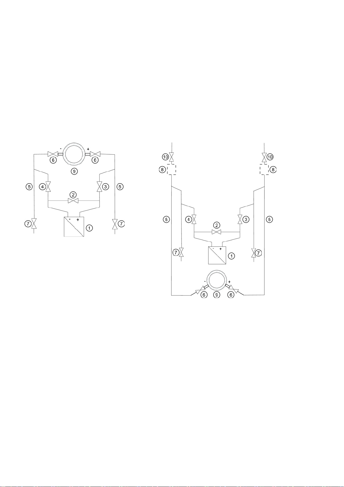
Procedure
5.4.3
Commissioning for liquids
Usual arrangement
Special arrangement
①
Pressure transmitter
⑦
Drain valves
②
Stabilizing valve
⑧
Gas collector
③, ④
Differential pressure valves
⑨
Differential pressure transducer
⑤
Differential pressure lines
⑩
Vent valves
⑥
Shut
Transmitter below
Transmitter above
differential pressure transducer
Condition
To commission the transmitter for gases, proceed as follows:
1. Open both the shut-off valves
2. Open the stabilizing valve
3. Open the differential pressure valve (③ or ④).
4. Check and if required correct the zero point when the start of scale value is 0 mbar (4 mA).
5. Close the stabilizing valve
6. Open the other differential pressure valve (
⑥ at the pressure tapping point.
②.
②.
③ or ④).
All valves are closed.
-off valves
the differential pressure transducer
vessels (optional)
the
SITRANS P DS III (7MF4.33.. 7MF4.34.. 7MF4.35..)
28 A5E03434626-03, 06/2013

Procedure
DANGER
Toxic liquids
● Before venting, make sure there is no liquid in the device or take the necessary safety precautions.
transmitters below the differential pressure transducer
transmitter above the differential pressure transducer
Danger of poisoning when the device is vented.
If toxic process media are measured with this device, toxic liquids can escape when the device is vented.
To commission the transmitter with liquids, proceed as follows:
1. Open both the shut-off valves
2. Open the stabilizing valve
3. With
4. Close both drain valves
5. Open the differential pressure valve ③ and the vent valve on the positive side of the transmitter ① slightly, until air-free
6. Close the vent valve.
7. Open the vent valve on the negative side of the transmitter
8. Close the differential pressure valve
9. Open the differential pressure valve
10. Close the vent valve on the negative side of the transmitter ①.
11. Open the differential pressure valve
12. Check and if required adjust the zero point (4 mA) if the start of scale value is 0 bar.
13. Close the stabilizing valve
14. Open the differential pressure valves (
free liquid escapes.
In the case of a
the air-free liquid escapes.
liquid escapes.
⑥ at the pressure tapping point.
②.
, open both blowout valves ⑦ one after the other until the air-
, open both vent valves ⑩ one after the other until
⑦ or vent valves ⑩.
① slightly, until air-free liquid escapes.
③.
④ until the liquid emerges and then close it.
③ by rotating it in half a turn.
②.
③ and ④) completely.
SITRANS P DS III (7MF4.33.. 7MF4.34.. 7MF4.35..)
A5E03434626-03, 06/2013
29
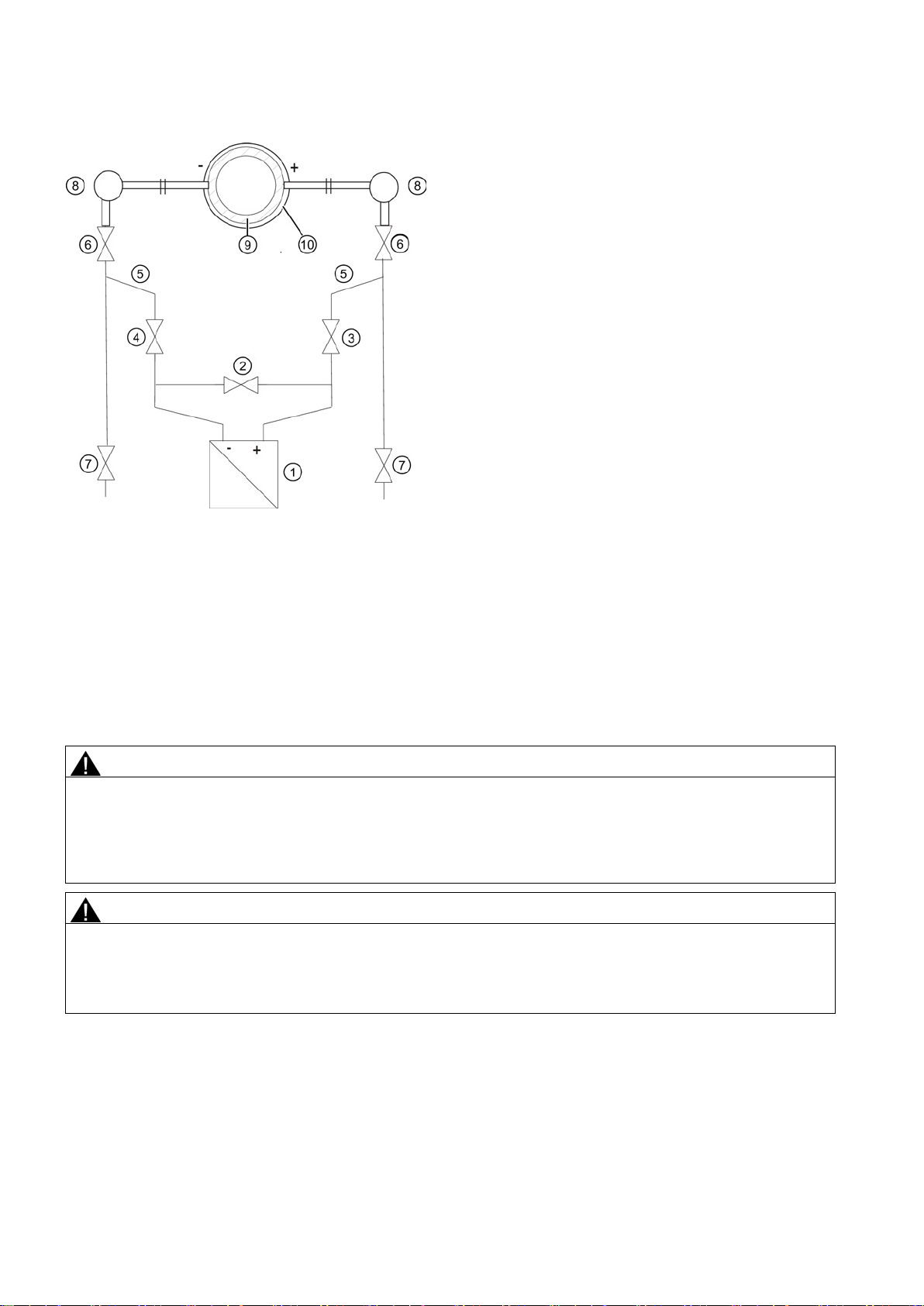
5.4.4
Commissioning with vapor
①
Pressure transmitter
⑦
Drain valves
②
Stabilizing valve
⑧
Condensate pots
③, ④
Differential pressure valves
⑨
Differential pressure transducer/Orifice plate
⑤
Differential pressure lines
⑩
Insulation
⑥
Shut-off valves
Condition
Procedure
WARNING
Hot vapor
● Follow the specified procedure for commissioning.
WARNING
Hot vapor
● Only open the drain valves ⑦ briefly, and close them again before vapor escapes.
Figure 5-2 Measuring steam
All valves are closed.
Danger of injury or damage to device.
If the shut-off valves
the transmitter
Danger of injury.
You can briefly open the drain valves
To commission the transmitter for vapor, proceed as follows:
1. Open both the shut-off valves
⑥ and the differential pressure valve ③ are both open and the stabilizing valve ② is then opened,
① can be damaged by the flow of vapor.
⑦ to clean the line. Hot vapor can escape in the process.
⑥ at the pressure tapping point.
2. Open the stabilizing valve
3. Wait until the steam in the differential pressure lines
SITRANS P DS III (7MF4.33.. 7MF4.34.. 7MF4.35..)
②.
⑤ and in the equalizing vessels ⑧ has condensed.
30 A5E03434626-03, 06/2013
 Loading...