

Siemens SITRANS P 7MF4232 Operating Instructions Manual
SITRANS P
Absolute pressure transmitter, DS series (Smart)
7MF4232
Operating Instructions C79000-B5676-C92-01

SIPART, SITRANS, SIMATIC
are Siemens registered trademarks.
All other product or system names are (registered) trademarks of their respective owners and must be treated
accordingly.
The reproduction, transmission or use of this document or its contents is not permitted without express written authority . Offenders will be liable
for damages.
All rights created by the granting of patents or registration of a design are reserved.
T echnical data subject to change without notice

SITRANS P
Absolute pressure transmitter, DS series (Smart)
(from the pressure transmitter series)
7MF4232
Operating Instructions

7MF4232Operating Instructions
2
C79000-B5676-C92-01

7MF4232 Operating Instructions
Contents
Page
1 Technical Description 5..................................................
1.1 Range of Application 5....................................................
1.2 How it works 5...........................................................
1.3 Technical Data 7.........................................................
1.4 Ordering data 11..........................................................
1.5 Dimensions 13............................................................
2 Installation 14............................................................
2.1 Installation 14.............................................................
2.1.1 Fixing with a mounting bracket 14..................................
2.1.2 Turning the measuring cell in relation to the housing 15...............
2.2 Electrical connection 16....................................................
2.3 Installing the analog indicator 18.............................................
2.4 Turning the digital indicator 18...............................................
3 Commissioning 19.......................................................
4 Operation 21.............................................................
4.1 Operation with PC/Laptop 21................................................
4.2 Operating from a HARTR-Communicator 21...................................
4.3 Operation on the transmitter 23..............................................
4.3.1 General 23......................................................
4.3.2 Setting the start of scale and full scale with the cover closed without viewing
window and activated key disable 24...............................
4.3.3 Operation with visible digital display and deactivated key lock 27.......
4.3.3.1 Setting start of scale and full scale with a pressure source 27..........
4.3.3.2 Setting start of scale and full scale without pressure transmitter 28.....
4.3.3.3 Correction of zero point 29........................................
4.3.3.4 Setting electrical damping 30......................................
4.3.3.5 ”Loop check” function 30..........................................
4.3.3.6 Output current in error situations 30................................
4.3.3.7 Disable pushbuttons and/or functions 31............................
4.3.3.8 Select display (current, %, pressure) 31.............................
4.3.3.9 Select engineering units 31........................................
4.4 Write protection 32.........................................................
5 Maintenance 33..........................................................
6 Conformance Certificates 34..............................................
C79000-B5676-C92-01
3

7MF4232Operating Instructions
.
!
Note
These instructions do not purport to cover all details or variations in equipment, nor to
provide for every possible contingency that may arise during installation, operation or
maintenance.
Should further information be desired or should particular problems arise that are not
covered sufficiently for the Purchaser’s purposes, the matter should be referred to the local
Siemens Sales Office.
The contents of this instruction manual shall not become part of or modify any prior or
existing agreement, commitment or relationship. The Sales Contract contains the entire
obligations of Siemens. The warranty contained in the contract between the parties is the
sole warranty of Siemens. Any statements contained herein do not create new warranties
or modify the existing warranty.
Warning
This equipment should only be installed and operated after qualified personnel have
ensured that suitable power supplies are available. These personnel must ensure that the
equipment is not subjected to any hazardous voltages during normal operation or when a
defect occurs in the system.
This equipment may be used under high pressure and with aggressive media. Improper
use of this equipment may therefore result in severe personal injury or extensive damage to
property.
The successful and safe operation of this equipment is dependent upon its proper handling,
installation, operation and maintenance.
Qualified person
For thepurposes of this manual, a qualified personis one who is familiar withthe installation, commissioning and operation of this equipment. In addition, the person must be:
. Trained and authorised to operate and service equipment/systems in accordance with established
safety practices relating to electrical circuits, high pressures and aggressive media.
. Trained in the proper care and use of protective equipment in accordance with established safety
practices.
. Trained in rendering first aid.
4
C79000-B5676-C92-01

7MF4232 Operating Instructions
1 Technical Description
1.1 Range of Application
The Smart version of the SITRANS P transmitter measures the absolute pressure of non-aggressive and
aggressive gases, steam and liquids.
Measuring spans between 8.3 mbar and 30 bar are possible. The output signal is a load-independent
direct current of 4 to 20 mA which is linearly proportional to the absolute pressure.
Transmitters with intrinsic safety and flame--proof enclosure protection type can be used in areas where
there is an explosion hazard (zone 1). The certificates of conformity satisfy the European standard
(CENELEC) the American standard (FM) or the Canadian standard (CSA).
The transmitters are available with various types of chemical seal for special applications, e.g. measuring
high viscous substances.
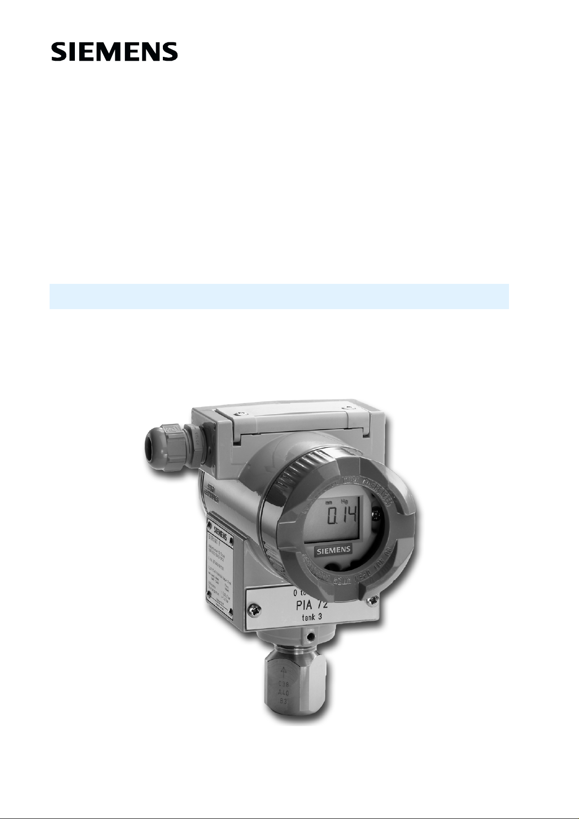
1.2 How it works
The pressure is transferred via the isolating diaphragm (2, fig. 1.1) and the liquid filling (3) to the silicon
absolute pressure sensor (4) and its measuring diaphragm distorted. Four doped piezo-resistors in bridge
circuit in the measuring diaphragm change their resistance as a result. This change in resistance causes
a bridge output voltage proportional to the input pressure which is transformed through a measuring
amplifier (1 1) in an analog-digital converter (12) into a digital signal. The measuring signal is evaluated
by a microcontroller (13), corrected with respect to linearity and temperature behavior and transformed
by a digital-analog converter (14) into the output current 4 to 20 mA.
The measuring cell-specific data and the data for parameterization of the transmitter are stored in a
non-volatile EEPROM.
The cable termination point and the electronics’ side are arranged opposite.
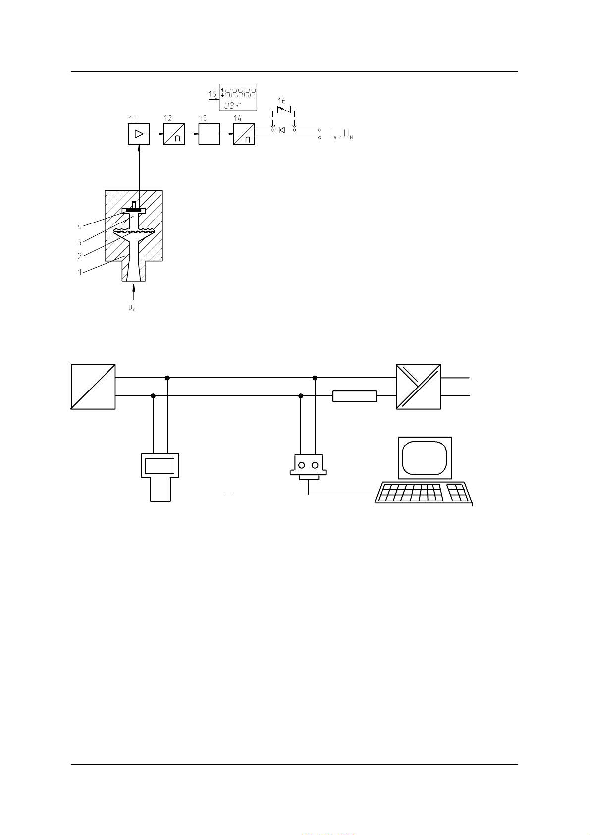
The transmitter is parameterized with a PC/laptop or HARTR-Communicator. The PC/laptop is
connected to the two-wire circuit via the HARTR-Modem. The signals necessary for communication
accordingtotheHARTRprotocol, Revision 5.1, are superimposed on the output current according to the
frequency shift keying method (FSK, F
The following parameters can be set or their current settings interrogated:
- Measuring point number
- Measuring point description
-Text
- Upper limit of output signal
- Measuring limit
- Transmitter design (e.g. materials)
- Measuring range *
- Engineering unit *
- Measured value in mA, % or engineering units *
- Damping *
- ”Loop check” function *
- Output current in the event of an error *
- Pushbutton and/or function disable *
requency Shift Keying).
In addition to the parameterization with a PC/laptop or HARTR-Communicator (see Figure 1.2) the start
of scale and full scale can be ”fixed” on the transmitter with three external pushbuttons; the parameters
m ar k ed wit h * c an be s et dir ec t ly on t he t r ans m it t er us ing t he digit al dis play wit hout opening t he hous ing.
C79000-B5676-C92-01
5
I
A
U
H
p
e
#
μC
#
1 Process cover
2 Overload diaphragm
3 Filling liquid
4 Silicon absolute pressure sensor
11 Measuring amplifier
12 Analog-Digital converter
13 Microcontroller
14 Digital-Analog converter
15 Digital indicator
16 Analog indicator (option)
Figure 1.1 SITRANS P absolute pressure transmitter, function diagram
7MF4232Operating Instructions
Output current
Auxiliary power
Input variable pressure
+
---
SITRANS P
Transmitter
HARTR-
Communicator
or
230 Ω
to 500 Ω
(230 Ω to 1100 Ω for HartR communicator)
HARTR-
Modem
RS-232-C
+
---
Auxiliary power
PC/Laptop
Figure 1.2 Communication between PC/Laptop or HARTR-Communicator and SITRANS P
transmitter
6
C79000-B5676-C92-01

7MF4232 Operating Instructions
1.3 Technical Data
Functional data
Measuring spans and overrange limits
Variable measuring spans Overrange limits
8.3 to 250 mbar ≙ 0.83 to 25 kPa
43 to 1300 mbar ≙ 4.3 to 130 kPa
160 to 5000 mbar ≙ 16 to 500 kPa
1000 to 30000 mbar ≙ 100 to 3000 kPa
.
Lower measuring limit
Silicone oil filling 0 mbar (abs)
Inert filling liquid --20 _Cto60_C:
Note for the 250 mbar measuring cell:
This measuring cell is designed for operation within the measuring limits 0 mbar (abs) to
250 mbar (abs). When storing under normal ambient pressure of about 1000 mbar (abs)
the measuring cell is in the overload state. An overrange error may occur in this state. The
overrange error disappears when operating within the measuring limits. Then the
transmitter operates within its specification again; it may be necessary to readjust the start
of the measuring range.
In pressure measurements with repeated exceeding of the measuring limits (e.g. batch
processes with transitions between vacuum and ventilation) a measuring cell with a
maximum range of 1300 mbar should be selected to avoid overrange errors.
30 mbar(abs)
6 bar
10 bar
30 bar
100 bar
+60 _C to +100 _C:
Temp . i n _ C--60_ C
30 mbar(abs) +20 mbar(abs) x
Upper measuring limit 0 and 100 % of the max. measuring span
Start of scale anywhere between the measuring limits
Auxiliary power
Terminal voltage on the transmitter 1 1 to 45 V, DC
1 1 to 30 V DC in intrinisically safe operation
Ripple U
Noise U
Output signal 4 to 20 mA
lower limit 3.84 mA
upper limit 20.5 to 22.0 mA
in the event of an error 3.6 mA or 22.8 mA
ripple I
1)
adjustable with PC/Laptop or HART-Communicator; factory set 20.5 mA.
≤0.2V(47to125Hz)
pp
≤1.2mV(0.5to10kHz)
rms
1)
≤0.5 % of the maximum output current
pp
()
_ C
C79000-B5676-C92-01
7

7MF4232Operating Instructions
x
Load
U
– 11 V
R ≤
U
H
0, 023 A
: auxiliary power in V
H
in Ω,
230 to 500 Ω for communication with PC/Laptop
230 to 1100 Ω for communication with ≥230 Ω
HARTR-Communicator
Electrical damping
variable time constant 0 to 100 s
Current sensor adjustable 3.6 mA to 22.8 mA
Permissible ambient temperature
1)
-- 4 0 _Cto+85_C silicone oil
-- 2 0 _Cto+85_C inert filling liquid
Observe temperature class in hazardous locations!
Permissible medium temperature --40 _C to +100 _C silicone oil
-- 2 0 _C to +100 _C inert filling liquid
Permissible storage temperature --50 _Cto+85_C
Condensation permitted
Transmission behavior
Start of scale 0 bar, rising characteristic, silicone oil filling and isolating diaphragm made of stainless
steel. All data refer to the output span.
Measuring span ratio MSma
Measurement error when calibrating fixed
point (including hysteresis and reproducibi-
r=
MS
≤0.1 % at r ≤10
≤0.2 % at r >10
MSmax = maximum span
MS = set span
lity)
Time constant T
at 20 _C
63
about 0.2 ms
(without electrical damping)
Long-term drift ≤0.2 % every 12 months at max. span
Influence of the ambient temperature
at --10 _Cto+60_C ≤(0.1 r+0.2) %
at --40 _Cto--10_C and
≤(0.1 r+0.15) % / 10 K
+60 _Cto+85_C
Influence of the auxiliary power ≤0.005 % per 1 V change in voltage
Influence of the installation position ≤0.05 mbar to 10_ of deviation
Electromagnetic compatibility
Resistance to interference EN 50082-2 and NAMUR NE 21, May 1993
Spurous emission EN 50081-1
1)
Note:
At temperatures below --20 _C the digital indicator may no longer be legible under some circumstances due to its inertia.
8
C79000-B5676-C92-01

7MF4232 Operating Instructions
Instrument design
Electrical connection Screw terminals or connector Han 7 D
1) 2)
For screw terminals cable inlet via
1) 2)
compression gland Pg 13.5
female thread M20¢1.5
1
female thread
1)
Not in flame--proof enclosure type of protection
2)
Not in FM exp/CSA exp type of ignition protection
/2-- 1 4 N P T
2)
or
or
Type of protection according to EN 60529 IP65
Process connection Connecting shank G
1
/2according to DIN 16288
or
1
female thread
/2-- 1 4 N P T or
oval flange and connection pin of stainless steel,
fastening thread:
7
-
/16--20 UNF
-M10
Materials of the components that come
into contact with the medium
Connection pin stainless steel, material no. 1.4401
Overload diaphragm stainless steel, material no. 1.4404 or
Hastelloy C276, material no. 2.4819
Measuring cell filling silicone oil or inert filling liquid
Electronics housing low-copper die-cast aluminum GD--AISi 12,
polyester-based lacquer,
stainless steel rating plate
Mounting bracket (optional) stee l, galvanized and yellow-passivate d or stainles s steel
Digital indicator Housing cover with or without viewing window accor-
ding to order, see also chapter 4.3.1, page 23
Analog indicator (optional) with linear scale 0 to 100 % or customer-specific scale
Weight about 1.5 kg (without options)
Explosion protection
according to DIN EN 50 014, DIN EN 50 018 and DIN EN 50 020 (CENELEC)
Intrinsic safety ”i”
Identification EEx ia IIC T4 or T5 or T6
Certificate of conformity PTB No. Ex-94.C.2090
Max. ambient temperature +85 _C in temperature class T4
+75 _C in temperature class T5
+60 _C in temperature class T6
Connection to certified intrinsically safe circuits with the maximum
values:
=30V,Ik= 100 mA, P = 750 mW
U
o
Effective internal inductance L
Effective internal capacitance C
≤0.6 mH
i
≤8nF
i
C79000-B5676-C92-01
9

Flame--proof enclosure ”d”
Identification EEx d IIC T5 or T6
Certificate of conformity PTB No. Ex-94.C.1021
Max. ambient temperature +85 _C in temperature class T5
+75 _C in temperature class T6
Communication (PC/laptop or HARTR-Communicator with SITRANS P transmitter)
Load with connection of
HARTR-Modem 230 to 500 Ω
HARTR-Communicator 230 to 1 100 Ω
Cable Shielded two--core: ≤3.0 km
Shielded multicore: ≤1.5 km
Protocol HARTR, Revision 5.1
PC/laptop requirements IBM--compatible
RAM ≥32 Mbyte
Hard disk at least 70 Mbyte
RS-232-C interface
VGA graphics
7MF4232Operating Instructions
Software for PC/laptop Windows 95 or Windows NT 4.0 and SIMATIC PDM
10
C79000-B5676-C92-01
 Loading...