

Siemens SITRANS P500 HART Compact Operating Instructions


English ............................................................................................... 3
Deutsch ............................................................................................ 34
Français ........................................................................................... 65
Español ............................................................................................ 96
Italiano ............................................................................................ 127
Nederlands ...................................................................................... 158
1

SITRANS
Pressure transmitter
SITRANS P500 with HART
Compact Operating Instructions
Legal information
Warning notice system
DANGER
indicates that death or severe personal injury will result if proper precautions are not taken.
WARNING
indicates that death or severe personal injury may result if proper precautions are not taken.
CAUTION
indicates that minor personal injury can result if proper precautions are not taken.
NOTICE
indicates that property damage can result if proper precautions are not taken.
Qualified Personnel
personnel qualified
Proper use of Siemens products
WARNING
Siemens products may only be used for the applications described in the catalog and in the relevant technical documentation. If products
problems. The permissible ambient conditions must be complied with. The information in the relevant documentation must be observed.
1
Introduction
1.1
Purpose of this documentation
See also
This manual contains notices you have to observe in order to ensure your personal safety, as well as to prevent damage to property. The
notices referring to your personal safety are highlighted in the manual by a safety alert symbol, notices referring only to property damage
have no safety alert symbol. These notices shown below are graded according to the degree of danger.
If more than one degree of danger is present, the warning notice representing the highest degree of danger will be used. A notice warning of
injury to persons with a safety alert symbol may also include a warning relating to property damage.
The product/system described in this documentation may be operated only by
the relevant documentation, in particular its warning notices and safety instructions. Qualified personnel are those who, based on their
training and experience, are capable of identifying risks and avoiding potential hazards when working with these products/systems.
Note the following:
and components from other manufacturers are used, these must be recommended or approved by Siemens. Proper transport, storage,
installation, assembly, commissioning, operation and maintenance are required to ensure that the products operate safely and without any
These instructions are a brief summary of important features, functions and safety information, and contain all information
required for safe use of the device. It is your responsibility to read the instructions carefully prior to installation and
commissioning. In order to use the device correctly, first review its principle of operation.
The instructions are aimed at persons who mechanically assemble the device, connect it electrically, and start it up.
To achieve optimum usage of the device, read the detailed version of the manual.
for the specific task in accordance with
Instructions and manuals (http://www.siemens.com/processinstrumentation/documentation)
© Siemens AG 2014. All rights reserved
A5E02344532-04, 12/2014
3

1.2
History
Edition
Firmware and hardware
identity nameplate
System integration
Installation path for
PDM
Note
HW: 11.01.01
1.3
Purpose
Overview
1.4
Checking the consignment
WARNING
Using a damaged or incomplete device
• Do not use damaged or incomplete devices.
This history establishes the correlation between the current documentation and the valid firmware of the device.
The documentation for this edition is applicable for the following firmware:
12/2014 FW: 35.02.02
FW: 35.03.00
Depending on the variant, the pressure transmitter measures corrosive, non-corrosive and hazardous gases, vapors and
liquids.
With appropriate configuration, you can also use the differential pressure transmitter for the following measurement types:
● Level
● Volume
● Mass
● Volume flow
● Mass flow rate
The output signal is always a load-independent direct current between 4 and 20 mA upon which a HART protocol is
superimposed.
You can install the "Intrinsically safe" or "Flameproof enclosure" version of the transmitter in hazardous areas. The devices
have an EC type-examination certificate and meet the regulations applicable to them, for example, the harmonized
CENELEC standards in Europe.
Transmitters with remote seals of different shapes can be delivered for special applications. For example, measuring highviscosity substances is a special application.
Operate the device in accordance with the specifications in section Technical data (Page 27).
For additional information, please refer to the operating instructions for the device.
SIMATIC PDM 8.x SITRANS P500
1. Check the packaging and the device for visible damage caused by inappropriate handling during shipping.
2. Report any claims for damages immediately to the shipping company.
3. Retain damaged parts for clarification.
4. Check the scope of delivery by comparing your order to the shipping documents for correctness and completeness.
Danger of explosion in hazardous areas.
SITRANS P500 with HART
4 A5E02344532-04, 12/2014
1.5
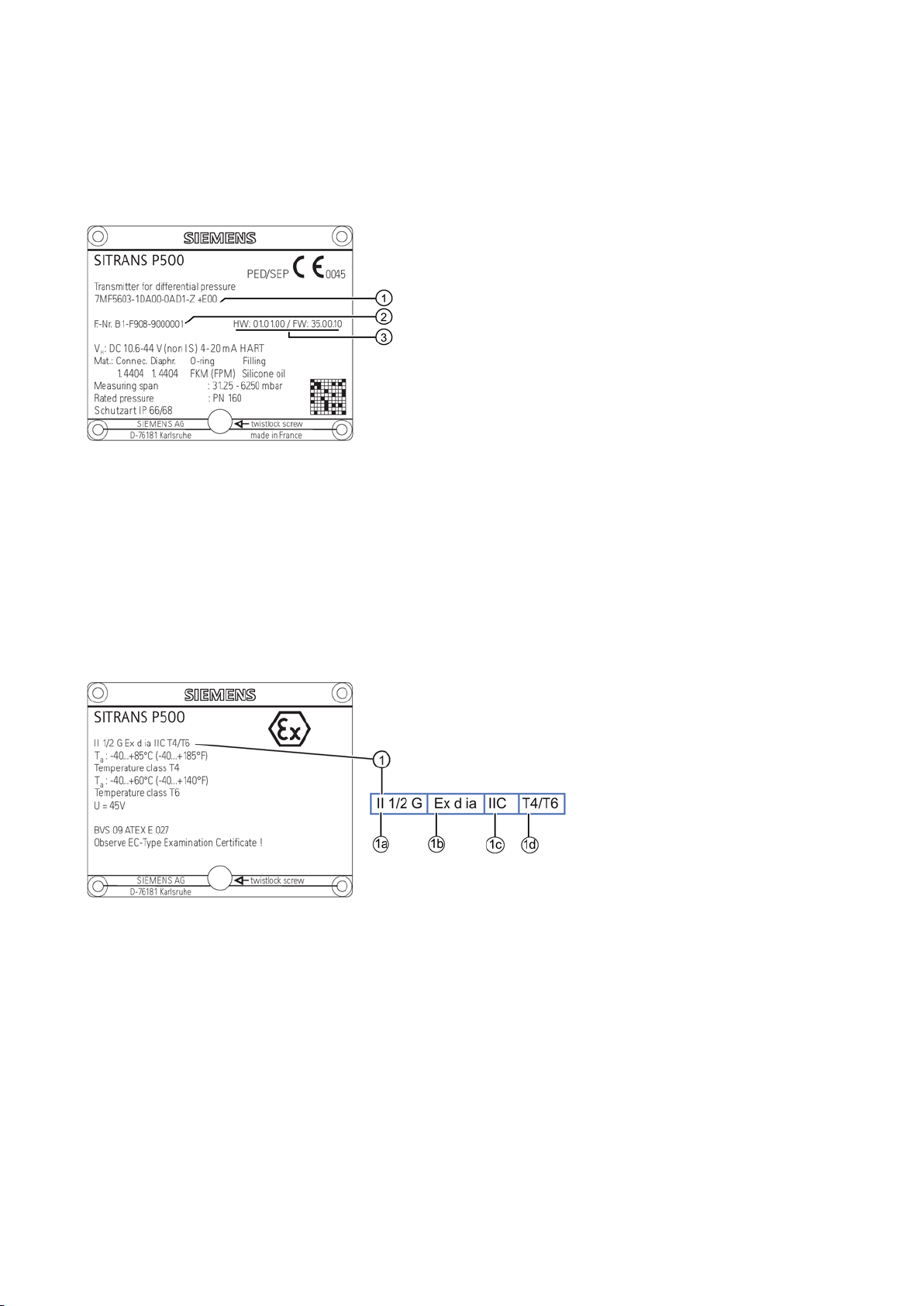
Nameplate layout
Nameplate with general information
①
Order number
②
Fabrication Number
③
HW:
FW: Firmware ID
Nameplate with approval information
①
Characteristics of the hazardous area
①
Category of the operating range
①
Type of protection
①
Group (gas, dust)
①
Maximum surface temperature (temperature class)
The nameplate with the order number and other important data, such as the design details and technical data can be found
on the side of the enclosure.
Figure 1-1 Example of a nameplate
The nameplate with approval information is on the opposite side. For the Ex-version of the pressure transmitter, the
information on the respective certificate is also listed.
Figure 1-2 Example of a nameplate
Hardware ID
a
b
c
d
SITRANS P500 with HART
A5E02344532-04, 12/2014
5
1.6
Transportation and storage
CAUTION
Insufficient protection during storage
Provide additional packaging as necessary.
1.7
Notes on warranty
2
Safety information
2.1
Precondition for use
Symbol
Explanation
2.1.1
Laws and directives
To guarantee sufficient protection during transport and storage, observe the following:
● Keep the original packaging for subsequent transportation.
● Devices/replacement parts should be returned in their original packaging.
● If the original packaging is no longer available, ensure that all shipments are properly packaged to provide sufficient
protection during transport. Siemens cannot assume liability for any costs associated with transportation damages.
The packaging only provides limited protection against moisture and infiltration.
•
Special conditions for storage and transportation of the device are listed in "Technical data" (Page 27).
The contents of this manual shall not become part of or modify any prior or existing agreement, commitment or legal
relationship. The sales contract contains all obligations on the part of Siemens as well as the complete and solely applicable
warranty conditions. Any statements regarding device versions described in the manual do not create new warranties or
modify the existing warranty.
The content reflects the technical status at the time of publishing. Siemens reserves the right to make technical changes in
the course of further development.
This device left the factory in good working condition. In order to maintain this status and to ensure safe operation of the
device, observe these instructions and all the specifications relevant to safety.
Observe the information and symbols on the device. Do not remove any information or symbols from the device. Always
keep the information and symbols in a completely legible state.
Observe the test certification, provisions and laws applicable in your country during connection, assembly and operation.
These include, for example:
● National Electrical Code (NEC - NFPA 70) (USA)
● Canadian Electrical Code (CEC) (Canada)
Further provisions for hazardous area applications are for example:
● IEC 60079-14 (international)
● EN 60079-14 (EC)
Consult operating instructions
SITRANS P500 with HART
6 A5E02344532-04, 12/2014

2.1.2
Conformity with European directives
Electromagnetic Compatibility EMC
2004/108/EC
Directive of the European Parliament and of the Council on the approximation of the
laws of the Member States relating to
Directive 89/336/EEC.
Atmosphère explosible ATEX
94/9/EC
Directive of the European Parliament and the Council on the approximation of the
laws of the Member States concerning equipment and protective systems intended
for use in potentially explosive atmospheres.
Pressure Equipment Directive PED
97/23/EC
Direc
laws of the Member States concerning pressure equipment.
2.2
Improper device modifications
WARNING
Improper device modifications
cancels the manufacturer's warranty and the product approvals.
2.3
Requirements for special applications
Note
Operation under special ambient conditions
We highly recommend that you contact your Siemens representative or our application department be
device under special ambient conditions as can be encountered in nuclear power plants or when the device is used for
research and development purposes.
2.4
Use in hazardous areas
Qualified personnel for hazardous area applications
WARNING
Unsuitable device for the hazardous area
Only use equipment that is approved for use in the intended hazardous area and labelled accordingly.
See also
The CE mark on the device is a sign of conformity with the following European directives:
electromagnetic compatibility and repealing
The standards applied can be found in the EC declaration of conformity for the device.
Danger to personnel, system and environment can result from modifications to the device, particularly in hazardous areas.
• Only carry out modifications that are described in the instructions for the device. Failure to observe this requirement
Due to the large number of possible applications, each detail of the described device versions for each possible scenario
during commissioning, operation, maintenance or operation in systems cannot be considered in the instructions. If you need
additional information not covered by these instructions, contact your local Siemens office or company representative.
tive of the European Parliament and of the Council on the approximation of the
fore you operate the
Persons who install, connect, commission, operate, and service the device in a hazardous area must have the following
specific qualifications:
● They are authorized, trained or instructed in operating and maintaining devices and systems according to the safety
regulations for electrical circuits, high pressures, aggressive, and hazardous media.
● They are authorized, trained, or instructed in carrying out work on electrical circuits for hazardous systems.
● They are trained or instructed in maintenance and use of appropriate safety equipment according to the pertinent safety
regulations.
Danger of explosion.
•
Technical data (Page 27)
SITRANS P500 with HART
A5E02344532-04, 12/2014
7

WARNING
Loss of safety of device with type of protection "Intrinsic safety Ex i"
Observe the specifications for the electrical data on the certificate and in Chapter "Technical data (Page 27)".
WARNING
Use of incorrect device parts in potentially explosive environments
Do not swap device parts unless the manufacturer specifically ensures compatibility of these parts.
WARNING
Risk of explosion due to electrostatic charge
NOTICE
Electrostatic-sensitive devices
Before working with modules, make sure that you discharge static from your body, for example by touching a grounded
Do not touch connector pins or conductor tracks on a module with the ESD notice.
3
Install
3.1
Basic safety instructions
WARNING
Wetted parts unsuitable for the process media
information in "Technical data" (Page 27).
If the device has already been operated in non-intrinsically safe circuits or the electrical specifications have not been
observed, the safety of the device is no longer ensured for use in hazardous areas. There is a danger of explosion.
• Connect the device with type of protection "Intrinsic safety" solely to an intrinsically safe circuit.
•
Devices and their associated device parts are either approved for different types of protection or they do not have
explosion protection. There is a danger of explosion if device parts (such as covers) are used for devices with explosion
protection that are not expressly suited for this type of protection. If you do not adhere to these guidelines, the test
certificates and the manufacturer warranty will become null and void.
• Use only device parts that have been approved for the respective type of protection in the potentially explosive
environment. Covers that are not suited for the "explosion-proof" type of protection are identified as such by a notice
label attached to the inside of the cover with "Not Ex d Not SIL".
•
To prevent the build-up of an electrostatic charge in a hazardous area, the key cover must be closed during operation and
the screws tightened.
The key cover may be opened temporarily at any time for the purposes of operating the pressure transmitter, even during
plant operation; the screws should then be tightened again.
The device contains electrostatic-sensitive devices (ESD). ESD can be destroyed by voltages far too low to be detected by
humans. These voltages can occur if you simply touch a component part or the electrical connections of a module without
being electrostatically discharged. The damage to a module caused by overvoltage cannot normally be detected
immediately; it only becomes apparent after a longer period of operating time has elapsed.
Protective measures against the discharge of static electricity:
• Make sure that no power is applied.
•
object.
• Devices and tools used must be free of static charge.
• Hold modules only by their edges.
•
Danger of injury or damage to device.
Hot, toxic and corrosive media could be released if the process medium is unsuitable for the wetted parts.
• Ensure that the material of the device parts wetted by the process medium is suitable for the medium. Refer to the
SITRANS P500 with HART
8 A5E02344532-04, 12/2014
WARNING
Unsuitable connecting parts
• Ensure that connecting parts (such as flange gaskets and bolts) are suitable for connection and process media.
Note
Material compatibility
Siemens can provide you with support concerning
are responsible for the selection of components. Siemens accepts no liability for faults or failures resulting from incompatible
materials.
WARNING
Exceeded maximum permissible operating pressure
The maximum permissible operating pressure depends on the device version. The device can be damaged if the operating
information on the nameplate and/or in "Technical data (Page 27)".
WARNING
Exceeded maximum ambient or process media temperature
Refer to the information in Chapter "Technical data (Page 27)".
WARNING
Open cable inlet or incorrect cable gland
Close the cable inlets for the electrical connections. Only use cable glands or plugs which are approved for the relevant
type of protection.
WARNING
Incorrect conduit system
regulations and the requirements stated in the relevant approvals.
WARNING
Incorrect mounting at Zone 0
Observe the standard IEC/EN 60079-14.
Danger of injury or poisoning.
In case of improper mounting hot, toxic and corrosive process media could be released at the connections.
selection of sensor components wetted by process media. However, you
Danger of injury or poisoning.
pressure is exceeded. Hot, toxic and corrosive process media could be released.
• Make sure that the device is suitable for the maximum permissible operating pressure of your system. Refer to the
Danger of explosion in hazardous areas.
Device damage.
• Make sure that the maximum permissible ambient and process media temperatures of the device are not exceeded.
Danger of explosion in hazardous areas.
•
Danger of explosion in hazardous areas as result of open cable inlet or incorrect conduit system.
• In the case of a conduit system, mount a spark barrier at a defined distance from the device input. Observe national
Danger of explosion in hazardous areas.
• Ensure sufficient tightness at the process connection.
•
SITRANS P500 with HART
A5E02344532-04, 12/2014
9
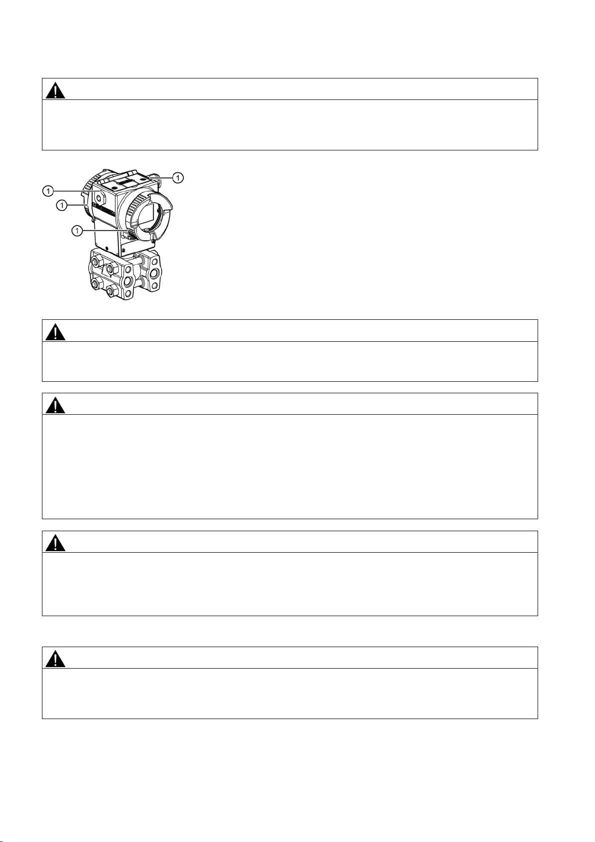
WARNING
Danger with "flameproof enclosure" protection
• Ensure that there is a space of at least 40 mm between the flameproof joint and the fixed parts.
①
Flameproof joint
WARNING
Loss of explosion protection
Close the device as described in Chapter "Connecting the device (Page 16)".
WARNING
Use of incorrect device parts in potentially explosive environments
Do not swap device parts unless the manufacturer specifically ensures compatibility of these parts.
CAUTION
Hot surfaces resulting from hot process media
Refer to the information in Chapter "Technical data (Page 27)".
CAUTION
External stresses and loads
Prevent severe external stresses and loads from acting on the device.
Danger of explosion in hazardous areas. An explosion may be caused by hot gas escaping from the flameproof enclosure
if there is too little space between it and the fixed parts.
Danger of explosion in hazardous areas if the device is open or not properly closed.
•
Devices and their associated device parts are either approved for different types of protection or they do not have
explosion protection. There is a danger of explosion if device parts (such as covers) are used for devices with explosion
protection that are not expressly suited for this type of protection. If you do not adhere to these guidelines, the test
certificates and the manufacturer warranty will become null and void.
• Use only device parts that have been approved for the respective type of protection in the potentially explosive
environment. Covers that are not suited for the "explosion-proof" type of protection are identified as such by a notice
label attached to the inside of the cover with "Not Ex d Not SIL".
•
Danger of burns resulting from surface temperatures above 70 °C (155 °F).
• Take appropriate protective measures, for example contact protection.
• Make sure that protective measures do not cause the maximum permissible ambient temperature to be exceeded.
Damage to device by severe external stresses and loads (e.g. thermal expansion or pipe tension). Process media can be
released.
•
SITRANS P500 with HART
10 A5E02344532-04, 12/2014
3.1.1
Installation location requirements
WARNING
Insufficient air supply
(Page 27)".
CAUTION
Aggressive atmospheres
Ensure that the device is suitable for the application.
NOTICE
Direct sunlight
3.1.2
Proper mounting
NOTICE
Incorrect mounting
requirements.
CAUTION
Loss of degree of protection
device if the enclosure is open or not properly closed. The degree of protection specified on the nameplate or in
Make sure that the device is securely closed.
See also
The device may overheat if there is an insufficient supply of air.
• Install the device so that there is sufficient air supply in the room.
• Observe the maximum permissible ambient temperature. Refer to the information in the section "Technical data
Damage to device through penetration of aggressive vapors.
•
Increased measuring errors.
• Protect the device from direct sunlight.
Make sure that the maximum ambient temperature is not exceeded. Refer to the information in the section Technical data
(Page 27).
The device can be damaged, destroyed, or its functionality impaired through improper mounting.
• Before installing ensure there is no visible damage to the device.
• Make sure that process connectors are clean, and suitable gaskets and glands are used.
• Mount the device using suitable tools. Refer to the information in Technical data (Page 27
) for installation torque
Damage to
Chapter "Technical data (Page 27)" is no longer guaranteed.
•
Connecting the device (Page 16)
SITRANS P500 with HART
A5E02344532-04, 12/2014
11
3.2
Disassembly
WARNING
Incorrect disassembly
Secure the remaining connections so that no damage can result if the process is started unintentionally.
3.3
Installation (except level)
3.3.1
Assembly
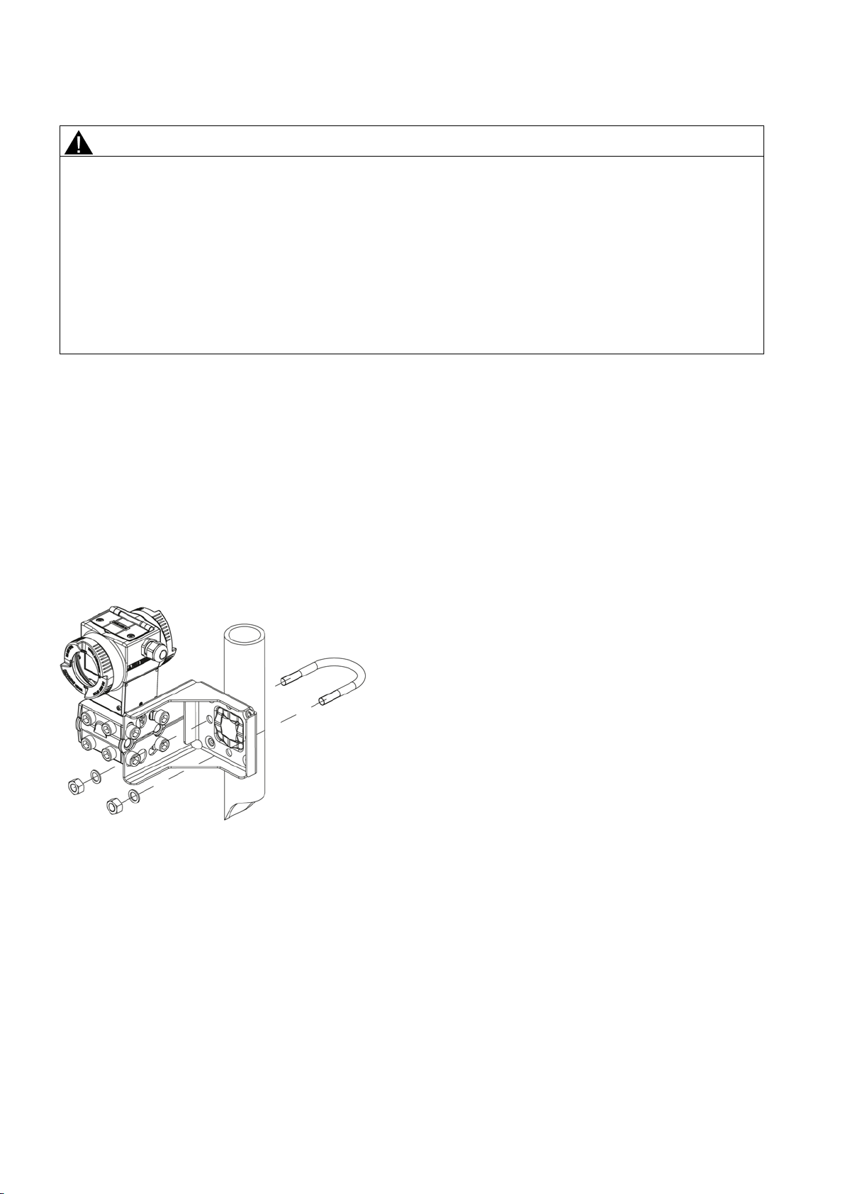
Fastening without the mounting bracket
Fastening with the mounting bracket
The following dangers may result through incorrect disassembly:
- Injury through electric shock
- Danger through emerging media when connected to the process
- Danger of explosion in hazardous area
In order to disassemble correctly, observe the following:
• Before starting work, make sure that you have switched off all physical variables such as pressure, temperature,
electricity etc. or that they have a harmless value.
• If the device contains dangerous media, it must be emptied prior to disassembly. Make sure that no environmentally
hazardous media are released.
•
You can fasten the pressure transmitter directly on both pressure caps.
You can use a tube clamp to fasten the mounting bracket to a horizontal or vertical mounting tube of diameter 50 mm (2 ").
Alternatively you can attach the mounting bracket to the wall.
Fasten the pressure transmitter mounting bracket using the four screws provided.
Figure 3-1 Fastening the pressure transmitter on the mounting bracket with horizontal differential pressure lines
SITRANS P500 with HART
12 A5E02344532-04, 12/2014

3.4
"Level" installation
3.4.1
Installation for level
Note
Seals are required for the installation. The seals must be compatible with the medium to be measured.
Seals are not included in the delivery.
Procedure
Figure 3-2 Fastening the pressure transmitter on the mounting bracket with vertical differential pressure lines
To install the pressure transmitter for level, proceed as follows:
1. Attach the seal to the container's mating flange.
Ensure that the seal is centrically positioned and that it does not restrict the movement of the flange's seal diaphragm in
any way as otherwise the tightness of the process connection is not guaranteed.
2. Screw on the pressure transmitter's flange.
3. Observe the installation position.
SITRANS P500 with HART
A5E02344532-04, 12/2014
13
3.4.2
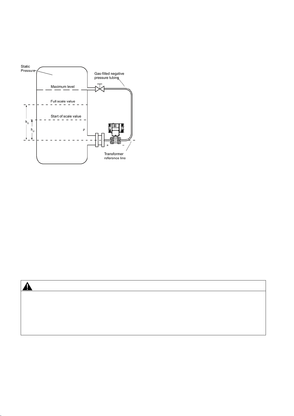
Connection of the negative pressure line to the closed vessel
Formula:
Start of scale value
Δp
Full scale value
Δp
h
Start of scale value
Δp
Start of scale value t
hO
Full scale value
ΔpME
Full scale value to be adjusted
p
Pressure
ρ
Density of the measured medium in the container
g
Acceleration due to gravity
Measurement assembly on a closed container:
no or little condensation separation
4
Connecting
4.1
Basic safety instructions
WARNING
Unsuitable cables and/or cable glands
After installation check that the cables are seated firmly.
When taking measurements in a closed container without or with little condensation formation, the negative pressure line is
not filled.
MA
ME
= ρ · g · hU
= ρ · g · hO
U
When taking measurements in a closed container with strong condensation formation, you must fill the negative pressure
line (mostly with the condensation of the measured medium) and install a condensation pot.
For measurement on open vessels there is no need to connect the minus pipework, since the minus side is open to the
atmosphere.
Danger of explosion in hazardous areas.
• Only use suitable cables and cable glands complying with the requirements specified in Chapter "Technical data
(Page 27)".
• Tighten the cable glands in accordance with the torques specified in Chapter "Technical data (Page 27)".
• When replacing cable glands use only cable glands of the same type.
•
MA
o be adjusted
SITRANS P500 with HART
14 A5E02344532-04, 12/2014
WARNING
Hazardous contact voltage in versions with 4-conductor extension
Observe the instructions in the 4-conductor extension operating manual for the electrical connection.
See also
WARNING
Improper power supply
be found in the certificates, in Chapter "Technical data (Page 27)" or on the nameplate.
WARNING
Unsafe extra-low voltage
Connect the device to an extra-low voltage with safe isolation (SELV).
WARNING
Lack of equipotential bonding
Exception
WARNING
Unprotected cable ends
• Protect unused cable ends in accordance with IEC/EN 60079-14.
WARNING
Improper laying of shielded cables
If grounding is required at both ends, use an equipotential bonding conductor.
WARNING
Connecting device in energized state
Exceptions
Exceptions for type of protection "Non-sparking nA" (Zone 2) are regulated in the relevant certificate
Danger of electrocution in case of incorrect connection.
•
Technical data (Page 27)
Danger of explosion in hazardous areas as result of incorrect power supply, e.g. using direct current instead of alternating
current.
• Connect the device in accordance with the specified power supply and signal circuits. The relevant specifications can
Danger of explosion in hazardous areas due to voltage flashover.
•
Danger of explosion through compensating currents or ignition currents through lack of equipotential bonding.
• Ensure that the device is potentially equalized.
: It may be permissible to omit connection of the equipotential bonding for devices with type of protection
"Intrinsic safety Ex i".
Danger of explosion through unprotected cable ends in hazardous areas.
Danger of explosion through compensating currents between hazardous area and the non-hazardous area.
• Only ground shielded cables that run into the hazardous area at one end.
•
Danger of explosion in hazardous areas.
• Connect devices in hazardous areas only in a de-energized state.
:
• Circuits of limited energy may also be connected in the energized state in hazardous areas.
•
SITRANS P500 with HART
A5E02344532-04, 12/2014
15

WARNING
Incorrect selection of type of protection
unrecognizable on the nameplate.
NOTICE
Ambient temperature too high
°C (68 °F) higher.
NOTICE
Incorrect measured values with incorrect grounding
• If necessary, ground the device using the "-" connection.
Note
Electromagnetic compatibility (EMC)
You can use this device in industrial environments, households and small businesses.
For metal housings there is an increased electromagnetic compatibility compared to high
protection can be inc
Note
Improvement of interference immunity
•
•
•
•
• Refer to HART communication information in Chapter "Technical data (Page 27)".
4.2
Connecting the device
Opening the device
Connecting the device
Danger of explosion in areas subject to explosion hazard.
This device is approved for several types of protection.
1. Decide in favor of one type of protection.
2. Connect the device in accordance with the selected type of protection.
3. In order to avoid incorrect use at a later point, make the types of protection that are not used permanently
Damage to cable sheath.
• At an ambient temperature ≥ 60 °C (140 °F), use heat-resistant cables suitable for an ambient temperature at least 20
The device must not be grounded via the "+" connection. It may otherwise malfunction and be permanently damaged.
-frequency radiation. This
reased by grounding the housing, see Chapter "Connecting the device (Page 16)".
Lay signal cables separate from cables with voltages > 60 V.
Use cables with twisted wires.
Keep device and cables in distance to strong electromagnetic fields.
Use shielded cables to guarantee the full specification according to HART.
1. Unscrew the cover of the electrical cable compartment. An identification text "FIELD TERMINALS" is provided at the side
of the housing.
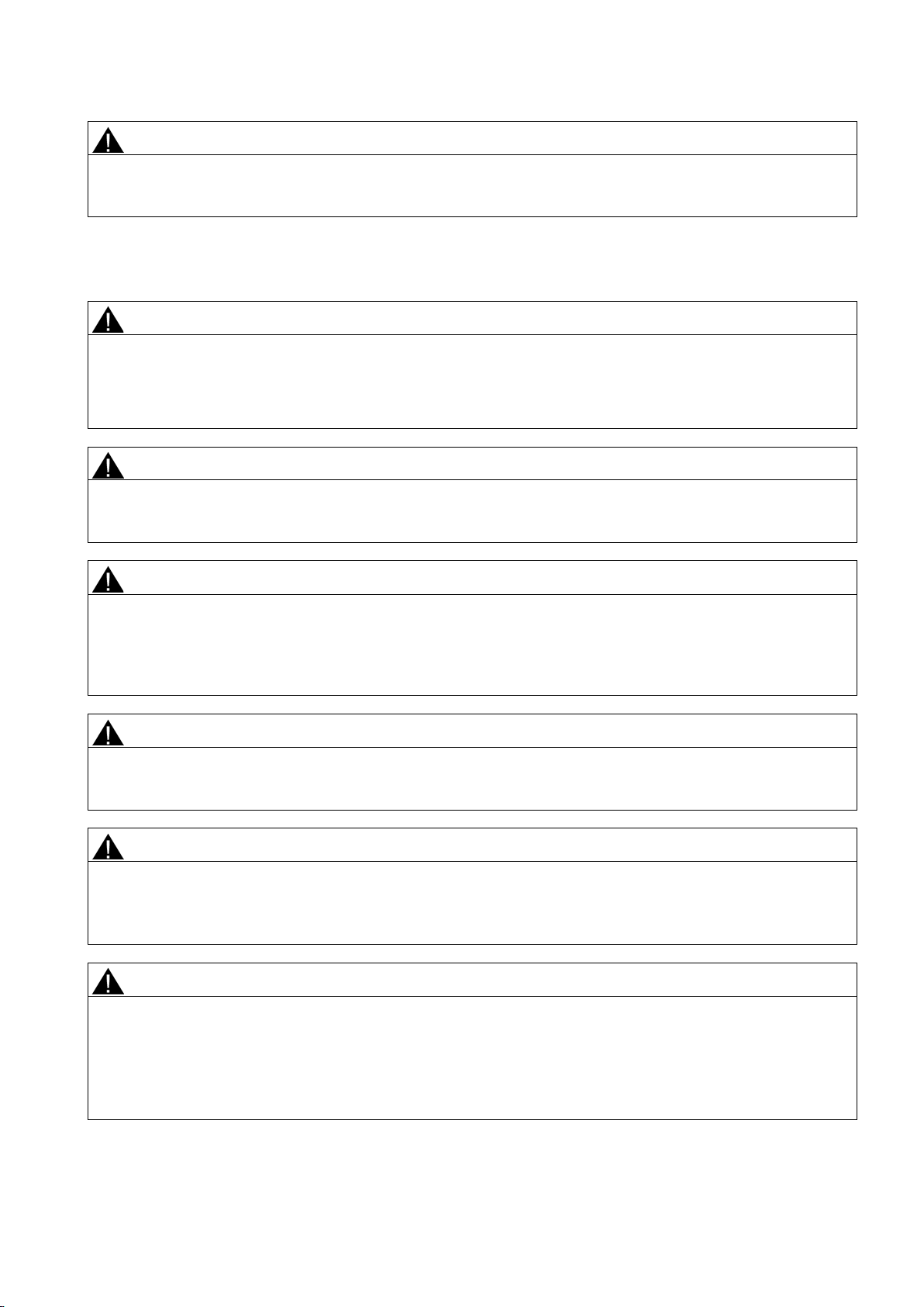
1. Insert the connecting cable through the cable gland ⑥.
2. Connect the device to the system with the protective conductor connection
3. Connect the wires to the connecting terminals
④ "+" and "-".
Observe the polarity when doing this. If necessary, ground the device using the "-" connection by connecting the
"-" connection to the ground terminal
SITRANS P500 with HART
16 A5E02344532-04, 12/2014
③.
⑤.
①
resistor
④
②
Auxiliary power
⑤
Protective conductor connector/equipotential bonding terminal
③
Ground terminal
⑥
Cable entry for auxiliary power/analog output
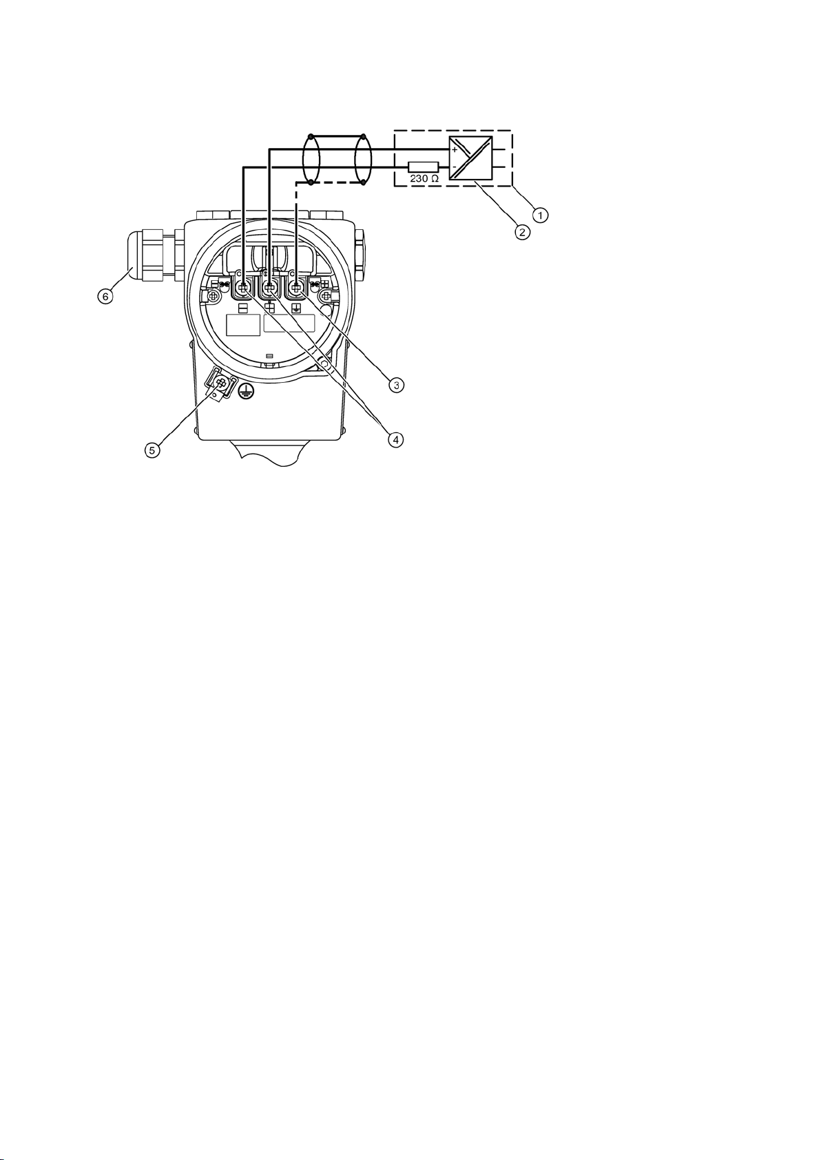
Closing the device
4. If necessary, ground the shield to the screw of the ground terminal ④. This is electrically connected with the external
protective conductor connection.
Power supply isolator with installed load
Figure 4-1 Schematic electrical connection
1. Screw the covers ②⑤ back on as far as they will go.
2. Secure each cover with the cover catch
3. Close the key cover
4. Tighten the screws in the key cover.
5. Check the tightness of the blanking plugs
①.
③.
④ and cable gland ⑥ in accordance with the degree of protection.
Connecting terminals
SITRANS P500 with HART
A5E02344532-04, 12/2014
17
①
Key cover
④
Blanking plug
②
Cover (front), optionally with inspection window
⑤
Cover (rear) for electrical terminal compartment
③
on the type of protection.
⑥
5
Commissioning
5.1
Basic safety instructions
DANGER
Toxic gases and liquids
Before venting ensure that there are no toxic gases or liquids in the device, or take the appropriate safety measures.
WARNING
Improper commissioning in hazardous areas
Before commissioning take the effect on other devices in the system into account.
Door contacts (front and rear)
Optional: The installed cover catches depend
Figure 4-2 View of the pressure transmitter: Left: Front right: View from rear
Danger of poisoning when venting the device: if toxic process media are measured, toxic gases and liquids can be
released.
•
Device failure or danger of explosion in hazardous areas.
• Do not commission the device until it has been mounted completely and connected in accordance with the information
in Chapter "Technical data (Page 27)".
•
Cable gland
SITRANS P500 with HART
18 A5E02344532-04, 12/2014
WARNING
Opening device in energized state
Exception
WARNING
Risk of explosion when media above 100 °C flows through the process flange
Note
Hot surfaces
Hot process medium and high ambient
• Take corresponding protective measures, for example wear protective gloves.
5.2
Introduction to commissioning
5.3
Differential pressure and flow rate
5.3.1
Safety notes for commissioning with differential pressure and flow rate
WARNING
Incorrect or improper operation
k screws are missing or are not sufficiently tight, and/or if the valves are operated incorrectly or improperly, it could
Measure
Ensure that the valves are operated correctly and properly.
Danger of explosion in areas subject to explosion hazard.
• Only open the device in a de-energized state.
• Check prior to commissioning that the cover, cover locks, and cable inlets are assembled in accordance with the
directives.
: Devices having the type of protection "Intrinsic safety Ex i" may also be opened in energized state in hazardous
areas.
Explosion protection is no longer guaranteed and the approval is nullified.
It is prohibited for media above 100 °C to continually flow through the process flange.
temperatures lead to hot surfaces which can cause burns.
Following commissioning, the pressure transmitter is immediately ready for use.
To obtain stable measured values, the pressure transmitter needs to be allowed to warm up for five minutes or so after the
power supply is switched on.
The operating data must correspond to the values specified on the nameplate. If you switch on the auxiliary power, the
pressure transmitter will operate.
The following commissioning cases are typical examples. Configurations different from those listed here may be meaningful
depending on the system configuration.
If the loc
lead to serious physical injuries or considerable damage to property.
• Make sure the locking screw and/or the vent valve are screwed in and tightened.
•
SITRANS P500 with HART
A5E02344532-04, 12/2014
19
5.3.2
Commissioning in gaseous environments
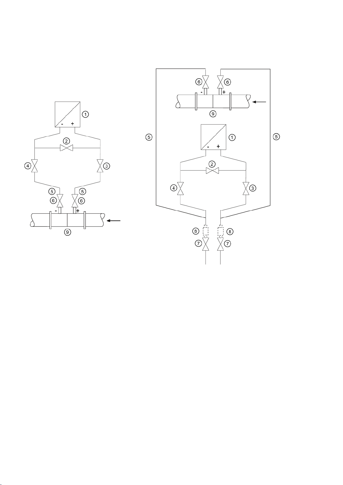
Usual arrangement
Special arrangement
①
Pressure transmitter
⑥
Shut
②
Stabilizing valve
⑦
Drain valves
③, ④
Differential pressure valves
⑧
Condensate vessels (optional)
⑤
Differential pressure lines
⑨
Differential pressure transducer
Pressure transmitter above
transducer
Pressure transmitter below
differential pressure transducer
Prerequisite
Procedure
All shut-off valves are closed.
To commission the pressure transmitter for gases, proceed as follows:
1. Open both the shut-off valves ⑥ at the pressure tapping point.
2. Open the stabilizing valve
3. Open the differential pressure valve (
the differential pressure
②.
③ or ④).
-off valves
the
4. Check and if required correct the zero point when the start of scale value is 0 mbar (4 mA).
5. Close the stabilizing valve
SITRANS P500 with HART
20 A5E02344532-04, 12/2014
②.
5.3.3
Commissioning for liquids
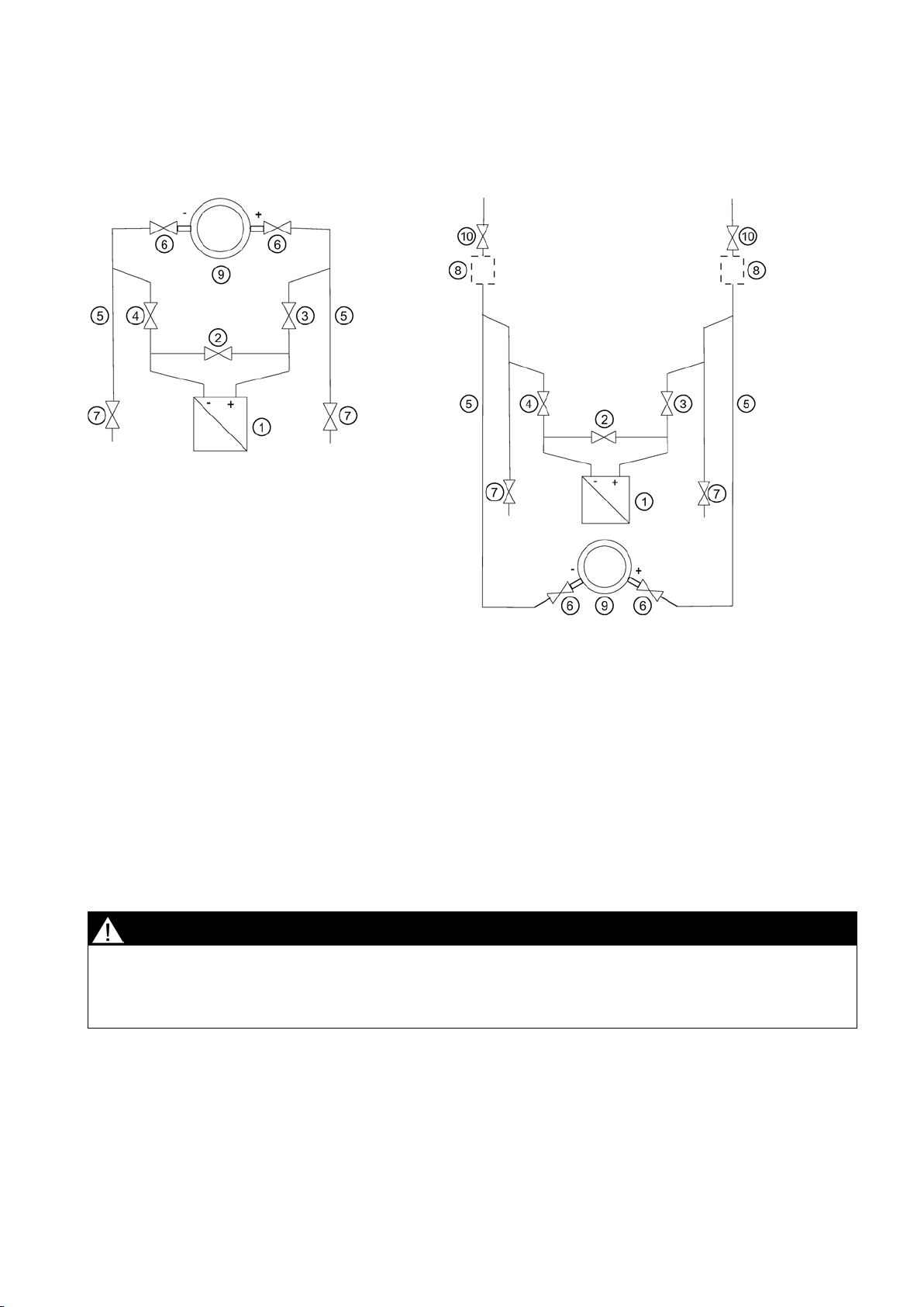
Usual arrangement
Special arrangement
①
Pressure transmitter
⑦
Drain valves
②
Stabilizing valve
⑧
Gas collector vessels (optional)
③, ④
Differential pressure valves
⑨
Differential pressure transducer
⑤
Differential pressure lines
⑩
Vent valves
⑥
Shut
Pressure transmitter below
transducer
Pressure transmitter above
differential pressure transducer
Prerequisite
Procedure
DANGER
Toxic liquids
Before venting, make sure there is no liquid in the device or take the necessary safety precautions.
6. Open the other differential pressure valve (③ or ④).
All valves are closed.
Danger of poisoning when the device is vented.
If toxic process media are measured with this device, toxic liquids can escape when the device is vented.
•
To commission the pressure transmitter for liquids, proceed as follows:
-off valves
the differential pressure
the
1. Open both the shut-off valves ⑥ at the pressure tapping point.
2. Open the stabilizing valve
SITRANS P500 with HART
A5E02344532-04, 12/2014
②.
21
pressure transmitter below the differential pressure transducer
pressure transmitter above the differential pressure transducer
5.3.4
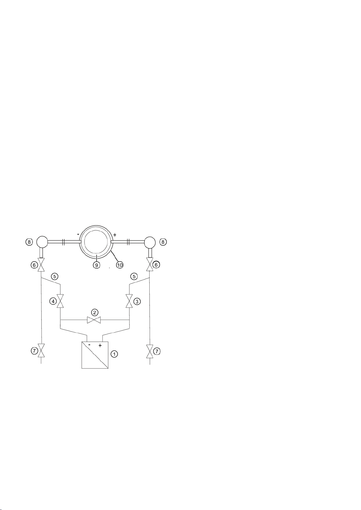
Commissioning with vapor
①
Pressure transmitter
⑦
Drain valves
②
Stabilizing valve
⑧
Condensate pots
③, ④
Differential pressure valves
⑨
Differential pressure transducer/Orifice plate
⑤
Differential pressure lines
⑩
Insulation
⑥
Shut-off valves
Prerequisite
3. With a
4. Close both drain valves ⑦ or vent valves ⑩.
5. Open the differential pressure valve
6. Close the vent valve.
7. Open the vent valve on the negative side of the pressure transmitter
8. Close the differential pressure valve
9. Open the differential pressure valve
10. Close the vent valve on the negative side of the pressure transmitter
11. Open the differential pressure valve
12. Check and if required adjust the zero point (4 mA) if the start of scale value is 0 bar.
13. Close the stabilizing valve
14. Open the differential pressure valves (
until the air-free liquid escapes.
In the case of a
other until the air-free liquid escapes.
③ and the vent valve on the positive side of the pressure transmitter ① slightly,
until fluid escapes without bubbles.
③.
④ until the liquid emerges and then close it.
③ by rotating it in half a turn.
②.
③ and ④) completely.
, open both blowout valves ⑦ one after the other
, open both vent valves ⑩ one after the
① slightly, until fluid escapes without bubbles.
①.
Figure 5-1 Measuring steam
All valves are closed.
SITRANS P500 with HART
22 A5E02344532-04, 12/2014

Procedure
WARNING
Hot vapor
Follow the specified procedure for commissioning.
WARNING
Hot vapor
Danger of injury or damage to device.
If the shut-off valves
the pressure transmitter
•
Danger of injury.
You can briefly open the drain valves
• Only open the drain valves ⑦ briefly, and close them again before vapor escapes.
To commission the pressure transmitter for vapor, proceed as follows:
1. Open both the shut-off valves ⑥ at the pressure tapping point.
⑥ and the differential pressure valve ③ are both open and the stabilizing valve ② is then opened,
① can be damaged by the flow of vapor.
⑦ to clean the line. Hot vapor can escape in the process.
2. Open the stabilizing valve
3. Wait until the steam in the differential pressure lines
4. Open the differential pressure valve
until air-free condensate escapes.
5. Close the vent valve.
6. Open the vent valve on the negative side of the pressure transmitter
bubbles.
7. Close the differential pressure valve
8. Open the differential pressure valve
9. Close the vent valve on the negative side
10. Open the differential pressure valve
11. Check and if necessary correct the zero point (4 mA) with a start of scale value of 0 bar.
The measuring result is only error-free if the differential pressure lines
the same temperature. The zero calibration must be repeated if required if these conditions are fulfilled.
12. Close the stabilizing valve
13. Fully open the differential pressure valves
14. You can briefly open the drain valves
②.
⑤ and in the equalizing vessels ⑧ has condensed.
③ and the vent valve on the positive side of the pressure transmitter ① slightly,
① slightly, until condensate escapes without
③.
④ slightly, until condensate escapes without bubbles, then close it.
①.
③ by rotating it in half a turn.
⑤ have equally high condensate columns with
②.
③ and ④.
⑦ to clean the line.
15. Close the drain valve
SITRANS P500 with HART
A5E02344532-04, 12/2014
⑦ before vapor escapes.
23
6
Service and maintenance
6.1
Basic safety instructions
WARNING
Impermissible repair of explosion protected devices
Repair must be carried out by Siemens authorized personnel only.
WARNING
Impermissible accessories and spare parts
accessory or spare part.
WARNING
Use of incorrect device parts in potentially explosive environments
Do not swap device parts unless the manufacturer specifically ensures compatibility of these parts.
WARNING
Maintenance during continued operation in a hazardous area
Ensure that the atmosphere is explosion-free (hot work permit).
WARNING
Commissioning and operation with pending error
– Prevent renewed commissioning.
Danger of explosion in areas subject to explosion hazard.
•
Danger of explosion in areas subject to explosion hazard.
• Only use original accessories or original spare parts.
• Observe all relevant installation and safety instructions described in the instructions for the device or enclosed with the
Devices and their associated device parts are either approved for different types of protection or they do not have
explosion protection. There is a danger of explosion if device parts (such as covers) are used for devices with explosion
protection that are not expressly suited for this type of protection. If you do not adhere to these guidelines, the test
certificates and the manufacturer warranty will become null and void.
• Use only device parts that have been approved for the respective type of protection in the potentially explosive
environment. Covers that are not suited for the "explosion-proof" type of protection are identified as such by a notice
label attached to the inside of the cover with "Not Ex d Not SIL".
•
There is a danger of explosion when carrying out repairs and maintenance on the device in a hazardous area.
• Isolate the device from power.
- or -
•
If an error message appears, correct operation in the process is no longer guaranteed.
• Check the gravity of the error.
• Correct the error.
• If the error still exists:
– Take the device out of operation.
SITRANS P500 with HART
24 A5E02344532-04, 12/2014
WARNING
Hot, toxic or corrosive process media
Before opening or removing the device ensure that process media cannot be released.
WARNING
Improper connection after maintenance
WARNING
Use of a computer in a hazardous area
Ensure that the atmosphere is explosion-free (hot work permit).
CAUTION
Releasing key lock
Make sure that only authorized personnel may cancel the key locking of devices for safety-related applications.
CAUTION
Hot surfaces
After carrying out maintenance, remount touch protection measures.
NOTICE
Electrostatic-sensitive devices
Do not touch connector pins or conductor tracks on a module with the ESD notice.
Danger of injury during maintenance work.
When working on the process connection, hot, toxic or corrosive process media could be released.
• As long as the device is under pressure, do not loosen process connections and do not remove any parts that are
pressurized.
•
Danger of explosion in areas subject to explosion hazard.
• Connect the device correctly after maintenance.
• Close the device after maintenance work.
Refer to Chapter "Connecting the device (Page 16)".
If the interface to the computer is used in the hazardous area, there is a danger of explosion.
•
Improper modification of parameters could influence process safety.
•
Danger of burns during maintenance work on parts having surface temperatures exceeding 70 °C (158 °F).
• Take corresponding protective measures, for example by wearing protective gloves.
•
The device contains electrostatic-sensitive devices (ESD). ESD can be destroyed by voltages far too low to be detected by
humans. These voltages can occur if you simply touch a component part or the electrical connections of a module without
being electrostatically discharged. The damage to a module caused by overvoltage cannot normally be detected
immediately; it only becomes apparent after a longer period of operating time has elapsed.
Protective measures against the discharge of static electricity:
• Make sure that no power is applied.
• Before working with modules, make sure that you discharge static from your body, for example by touching a grounded
object.
• Devices and tools used must be free of static charge.
• Hold modules only by their edges.
•
SITRANS P500 with HART
A5E02344532-04, 12/2014
25

6.2
Maintenance and repair work
6.2.1
Defining the maintenance interval
WARNING
No maintenance interval has been defined
The maintenance interval will vary from site to site depending on corrosion resistance.
6.2.2
Checking the gaskets
Note
Checking the gaskets
At regular intervals, check that the enclosure seals of the pressure transmitter satisfy IP66 / IP68. Grease or replace the
gaskets if required.
6.2.3
Changing the measuring cell and application electronics
Related
6.3
Cleaning
WARNING
Dust layers above 5 mm
Remove dust layers in excess of 5 mm.
NOTICE
Penetration of moisture into the device
Make sure when carrying out cleaning and maintenance work that no moisture penetrates the inside of the device.
Cleaning the enclosure
Device failure, device damage, and risk of injury.
• Define a maintenance interval for regular tests in line with device use and empirical values.
•
Each of the individual components "Measuring cell" and "Electronics" has a non-volatile memory (EEPROM).
Measuring cell data (e.g.: measuring range, measuring cell material, oil filling) and user data of the application electronics
(e.g.: downscaling, additional electrical damping) are located in the measuring cell EEPROM. User data is lost when the
measuring cell is replaced. Application-specific data are not lost when the application electronics are changed.
You can backup user data before changing the measuring cell and reload it afterwards. Use an input device which supports
the HART protocol. (e.g. HART communicator, PC with HART modem and HART software or PC with HART modem and
PDM software). Factory settings will be used if user data is not backed up before the measuring cell is changed.
Technical developments enable advanced functions to be implemented in the firmware of the measuring cell or application
electronics. Further technical developments are indicated by modified firmware statuses (FW). The firmware status does not
affect whether the modules can be replaced. However, the scope of functions is limited to the function of existing
components.
If a combination of certain firmware versions of measuring cell and application electronics is not possible for technical
reasons, the device will identify this problem and go into "Fault current" mode. This information is provided via the HART
interface.
Danger of explosion in hazardous areas. Device may overheat due to dust build up.
•
Device damage.
•
● Clean the outside of the enclosure and the display window using a cloth moistened with water or a mild detergent.
● Do not use aggressive cleaning agents or solvents. Plastic components or painted surfaces could be damaged.
SITRANS P500 with HART
26 A5E02344532-04, 12/2014

WARNING
Electrostatic charge
Prevent electrostatic charging in hazardous areas.
6.3.1
Servicing the remote seal measuring system
NOTICE
Improper cleaning of diaphragm
• Do not use sharp or hard objects to clean the diaphragm.
6.4
Return procedure
6.5
Disposal
Devices identified by this symbol may not be disposed of in the municipal waste
disposal services under observance of the Directive 2002/96/EC on waste electronic
and electrical equipment (WEEE).
They can be returned to the supplier within the
service. Observe the specific regulations valid in your country.
Note
Special disposal required
The device includes components that require special disposal.
• Dispose of the device properly and environmentally through a local waste disposal contractor.
7
Technical data
7.1
General
Input
(PS)
(0,4 ... 20 inH2O)
Danger of explosion in hazardous areas if electrostatic charges develop, for example, when cleaning plastic enclosures
with a dry cloth.
•
The remote seal measuring system usually does not need servicing.
If the mediums are contaminated, viscous or crystallized, it could be necessary to clean the diaphragm from time to time.
Use only a suitable solvent to remove the deposits from the diaphragm. Do not use corrosive cleaning agents. Prevent the
diaphragm from getting damaged due to sharp-edged tools.
Device damage. The diaphragm can be damaged.
Enclose the bill of lading, return document and decontamination certificate in a clear plastic pouch and attach it firmly to the
outside of the packaging. Any devices/replacement parts which are returned without a decontamination declaration will be
cleaned at your expense before further processing. For further details refer to the operating instructions.
EC or to a locally approved disposal
Measuring span (continuously adjustable) Measuring span Maximum operating pressure MAWP
SITRANS P500 with HART
A5E02344532-04, 12/2014
1 ... 50 mbar
1.25 … 250 mbar
(0.5 ... 100 inH
2
O)
160 bar (2320 psi)
27

Input
(2.51 ... 502 inH2O)
(12.54 … 2509 inH2O)
(2.33 … 465 psi)
Output
Output signal
4 … 20 mA, with modulated HART signal
Operating conditions
Ambient conditions
Note
Observe the temperature class in hazardous areas.
Display legible: -20 … +85 °C (-4 … +185 °F)
Storage temperature
-50 … +90 °C (-58 … 194 °F)
IP66/IP68 and NEMA 4x (with appropriate cable gland)
interference immunity
Permitted pressures
As per 97/23/EC Pressure Equipment Directive
Medium conditions
Process temperature
operation at a temperature > 100 °C.)
Mechanical design
Material
Wetted parts materials
Monel 400
screw
Graphite
Non-wetted parts materials
6.25 … 1250 mbar
0.032 … 6.25 bar
0.16 … 32 bar
• Ambient temperature
Pressure transmitter -40 … +85 °C (-40 … 185 °F)
Display not legible: -40 … -20 °C (-40 …-4 °F)
• Degree of protection
• Electromagnetic compatibility
Interference emission and
As per EN 61326 and NAMUR NE 21
•
Measuring cell with silicone oil
filling
-40 … +125 °C (-40 … 257 °F)
(Note that there is no medium flow through the pressure caps during normal
•
Seal diaphragm
• Stainless steel, mat. no. 1.4404/316L
• Hastelloy C276
•
Process connection and locking
PN 160: Stainless steel, mat. no. 1.4404/316L
O-ring Standard: Viton [FKM, (FPM)]
Optional:
• NBR
• PTFE (virginal)
• PTFE (glass-fiber reinforced)
• FFPM (Kalrez)
•
•
SITRANS P500 with HART
28 A5E02344532-04, 12/2014
 Loading...