

Siemens SITRANS P DS III, SITRANS P410 Operating Instructions Manual


SITRANS P DS III/P410 with
PROFIBUS PA
___________________
___________________
___________________
___________________
___________________
___________________
___________________
___________________
___________________
___________________
___________________
___________________
___________________
___________________
___________________
___________________
___________________
SITRANS
Pressure transmitter
SITRANS P DS III/P410 with
PROFIBUS PA
Operating Instructions
7MF4.34
02/2016
A5E00053276
Introduction
1
Safety information
2
Description
3
Installing / mounting
4
Connecting up
5
Operation
6
Operator control functions
via PROFIBUS
7
Functional safety
8
Configuration/project
engineering
9
Commissioning
10
Repair and maintenance
11
Interrupts, error and system
alarms
12
Technical data
13
Dimension drawings
14
Spare parts / accessories
15
Appendix
A
List of
abbreviations/acronyms
B
-08

Siemens AG
Division Process Industries and Drives
Postfach 48 48
90026 NÜRNBERG
GERMANY
Document order number: A5E00053276
Ⓟ
Copyright © Siemens AG 2016.
All rights reserved
Legal information
Warning notice system
DANGER
indicates that death or severe personal injury will result if proper precautions are not taken.
WARNING
indicates that death or severe personal injury may result if proper precautions are not taken.
CAUTION
indicates that minor personal injury can result if proper precautions are not taken.
NOTICE
indicates that property damage can result if proper precautions are not taken.
Qualified Personnel
personnel qualified
Proper use of Siemens products
WARNING
Siemens products may only be used for the applications described in the catalog and in the relevant technical
re required to ensure that the products operate safely and without any problems. The permissible
ambient conditions must be complied with. The information in the relevant documentation must be observed.
Trademarks
Disclaimer of Liability
This manual contains notices you have to observe in order to ensure your personal safety, as well as to prevent
damage to property. The notices referring to your personal safety are highlighted in the manual by a safety alert
symbol, notices referring only to property damage have no safety alert symbol. These notices shown below are
graded according to the degree of danger.
If more than one degree of danger is present, the warning notice representing the highest degree of danger will
be used. A notice warning of injury to persons with a safety alert symbol may also include a warning relating to
property damage.
The product/system described in this documentation may be operated only by
task in accordance with the relevant documentation, in particular its warning notices and safety instructions.
Qualified personnel are those who, based on their training and experience, are capable of identifying risks and
avoiding potential hazards when working with these products/systems.
Note the following:
documentation. If products and components from other manufacturers are used, these must be recommended
or approved by Siemens. Proper transport, storage, installation, assembly, commissioning, operation and
maintenance a
All names identified by ® are registered trademarks of Siemens AG. The remaining trademarks in this publication
may be trademarks whose use by third parties for their own purposes could violate the rights of the owner.
We have reviewed the contents of this publication to ensure consistency with the hardware and software
described. Since variance cannot be precluded entirely, we cannot guarantee full consistency. However, the
information in this publication is reviewed regularly and any necessary corrections are included in subsequent
editions.
for the specific
03/2016 Subject to change

Table of contents
1 Introduction ........................................................................................................................................... 11
2 Safety information ................................................................................................................................. 15
3 Description ............................................................................................................................................ 21
1.1 Purpose of this documentation ............................................................................................... 11
1.2 Product information ................................................................................................................. 11
1.3 History ..................................................................................................................................... 11
1.4 Scope of the instructions ........................................................................................................ 12
1.5 Checking the consignment ..................................................................................................... 12
1.6 Transportation and storage ..................................................................................................... 13
1.7 Notes on warranty ................................................................................................................... 13
2.1 Precondition for use ................................................................................................................ 15
2.1.1 Laws and directives ................................................................................................................ 15
2.1.2 Conformity with European directives ...................................................................................... 15
2.2 Improper device modifications ................................................................................................ 16
2.3 Requirements for special applications .................................................................................... 16
2.4 Use in hazardous areas .......................................................................................................... 17
2.4.1 Use of incorrect device parts in potentially explosive environments ...................................... 18
2.4.2 Electrostatic-sensitive devices ................................................................................................ 19
3.1 System configuration .............................................................................................................. 21
3.2 Application .............................................................................................................................. 22
3.3 SITRANS P DS III and SITRANS P410 .................................................................................. 24
3.4 Structure ................................................................................................................................. 24
3.5 Nameplate layout .................................................................................................................... 26
3.6 Measuring point label layout ................................................................................................... 27
3.7 Principle of operation .............................................................................................................. 27
3.7.1 Overview of mode of operation ............................................................................................... 27
3.7.2 Operation of the electronics .................................................................................................... 28
3.7.3 Principle of operation of the measuring cell ............................................................................ 29
3.7.3.1 Measuring cell for gauge pressure ......................................................................................... 30
3.7.3.2 Measuring cell for differential pressure and flow rate ............................................................. 31
3.7.3.3 Measuring cell for level ........................................................................................................... 32
3.7.3.4 Measuring cell for absolute pressure from the differential pressure series ............................ 33
3.7.3.5 Measuring cell for absolute pressure from the gauge pressure series ................................... 34
3.7.3.6 Measuring cell for gauge pressure, front-flush membrane ..................................................... 34
3.7.3.7 Measuring cell for absolute pressure, front-flush membrane ................................................. 35
3.8 Remote seal ............................................................................................................................ 36
SITRANS P DS III/P410 with PROFIBUS PA
Operating Instructions, 02/2016, A5E00053276-08
5

Table of contents
4 Installing / mounting .............................................................................................................................. 39
5 Connecting up....................................................................................................................................... 63
6 Operation .............................................................................................................................................. 71
3.9 SIMATIC PDM ........................................................................................................................ 36
3.10 PROFIBUS ............................................................................................................................. 37
3.10.1 Transmission technology ....................................................................................................... 37
3.10.2 Bus topology .......................................................................................................................... 37
3.10.3 Properties ............................................................................................................................... 38
4.1 Basic safety instructions ........................................................................................................ 39
4.1.1 Installation location requirements .......................................................................................... 43
4.1.2 Proper mounting..................................................................................................................... 43
4.2 Disassembly ........................................................................................................................... 44
4.2.1 Incorrect disassembly ............................................................................................................ 44
4.3 Installation (except level) ....................................................................................................... 45
4.3.1 Installation mounting (except for level) .................................................................................. 45
4.3.2 Installation (except level) ....................................................................................................... 46
4.3.3 Fastening ............................................................................................................................... 46
4.4 "Level" installation .................................................................................................................. 48
4.4.1 Instructions for level installation ............................................................................................. 48
4.4.2 Installation for level ................................................................................................................ 49
4.4.3 Connection of the negative pressure line .............................................................................. 50
4.5 "Remote seal" installation ...................................................................................................... 53
4.5.1 Remote seal installation ......................................................................................................... 53
4.5.2 Installation of the remote seal with the capillary line .............................................................. 54
4.6 Turing the measuring cell against housing ............................................................................ 60
4.7 Rotating the display ............................................................................................................... 61
5.1 Basic safety instructions ........................................................................................................ 63
5.1.1 Hazardous contact voltage in versions with 4-conductor extension ...................................... 63
5.1.2 Incorrect measured values with incorrect grounding ............................................................. 65
5.2 Connecting the device ........................................................................................................... 66
5.2.1 PROFIBUS assembly guidelines ........................................................................................... 66
5.3 Connecting the M12 connector .............................................................................................. 68
6.1 Overview of operation ............................................................................................................ 71
6.2 Basic safety instructions ........................................................................................................ 72
6.3 Information on operation ........................................................................................................ 72
6.4 Display ................................................................................................................................... 73
6.4.1 Display elements .................................................................................................................... 73
6.4.2 Units display ........................................................................................................................... 74
6.4.3 Error display ........................................................................................................................... 74
6.4.4 Mode display .......................................................................................................................... 75
6.4.5 Status display ......................................................................................................................... 76
6.5 Local operation....................................................................................................................... 76
6.5.1 Control elements for local operation ...................................................................................... 76
SITRANS P DS III/P410 with PROFIBUS PA
6 Operating Instructions, 02/2016, A5E00053276-08

Table of contents
7 Operator control functions via PROFIBUS ............................................................................................. 95
6.5.2 Operation using buttons .......................................................................................................... 79
6.5.3 Setting/adjusting electrical damping ....................................................................................... 79
6.5.4 Calibrate zero point ................................................................................................................. 80
6.5.5 Locking of buttons and functions ............................................................................................ 81
6.5.6 Measured value display .......................................................................................................... 82
6.5.7 Unit .......................................................................................................................................... 84
6.5.8 Bus address ............................................................................................................................ 88
6.5.9 Device operation type ............................................................................................................. 88
6.5.10 Position of the decimal point ................................................................................................... 90
6.5.11 Display of the zero-point adjustment ...................................................................................... 90
6.5.12 LO calibration .......................................................................................................................... 91
6.5.13 HI calibration ........................................................................................................................... 92
7.1 Communications structure for PROFIBUS PA ....................................................................... 95
7.1.1 Overview ................................................................................................................................. 95
7.1.2 Block model for collection and processing of measured values ............................................. 95
7.1.3 Pressure transducer block ...................................................................................................... 98
7.1.3.1 Pressure transducer block (transducer block 1) ..................................................................... 98
7.1.3.2 Linearization type function group .......................................................................................... 100
7.1.3.3 Units of the pressure transducer block ................................................................................. 102
7.1.4 Electronics temperature transducer block ............................................................................ 103
7.1.5 Analog input function block ................................................................................................... 104
7.1.6 Totalizer function block ......................................................................................................... 105
7.2 Overview of operating functions ........................................................................................... 106
7.3 Measurement ........................................................................................................................ 106
7.4 Settings ................................................................................................................................. 107
7.4.1 Overview of settings .............................................................................................................. 107
7.4.2 Settings ................................................................................................................................. 107
7.4.3 Pressure measurement......................................................................................................... 107
7.4.4 Level measurement .............................................................................................................. 108
7.4.5 Flow measurement ............................................................................................................... 111
7.4.6 Adjusting to a desired process value .................................................................................... 114
7.5 Electrical damping (filter time constant) ................................................................................ 116
7.6 Key lock and write protection ................................................................................................ 116
7.7 Warning and alarm limits ...................................................................................................... 117
7.8 Failure behavior .................................................................................................................... 119
7.8.1 Overview of failure behavior ................................................................................................. 119
7.8.2 Output ................................................................................................................................... 119
7.8.3 Totalizer output ..................................................................................................................... 119
7.9 Diagnostics functions ............................................................................................................ 120
7.9.1 Operating hours counter ....................................................................................................... 120
7.9.2 Calibration interval and service interval ................................................................................ 120
7.9.3 Clearing warning ................................................................................................................... 121
7.9.4 Clearing the alarm ................................................................................................................. 121
7.9.5 Min/max indicator .................................................................................................................. 122
7.10 Simulation ............................................................................................................................. 122
7.10.1 Overview of simulation .......................................................................................................... 122
SITRANS P DS III/P410 with PROFIBUS PA
Operating Instructions, 02/2016, A5E00053276-08
7

Table of contents
8 Functional safety .................................................................................................................................. 129
7.10.2 Simulating output ................................................................................................................. 123
7.10.3 Simulating input.................................................................................................................... 123
7.10.4 Simulating the pressure sensor ........................................................................................... 124
7.10.5 Simulating sensor and electronics temperature ................................................................... 125
7.11 Calibrating the sensor .......................................................................................................... 125
7.12 Correcting for positional error .............................................................................................. 126
7.13 Reset .................................................................................................................................... 127
7.13.1 Resetting to delivery state .................................................................................................... 127
7.13.2 Warm start/restart ................................................................................................................ 128
7.13.3 Resetting the PROFIBUS address....................................................................................... 128
8.1 Safety function ..................................................................................................................... 129
8.2 Safety Integrity Level (SIL) ................................................................................................... 130
8.3 Settings ................................................................................................................................ 132
8.4 Safety-related characteristics ............................................................................................... 132
8.5 Maintenance/check .............................................................................................................. 133
8.5.1 Overview .............................................................................................................................. 133
8.5.2 Checking safety function/proof test ...................................................................................... 134
8.5.2.1 Checking temperature sensors ............................................................................................ 135
8.5.2.2 Check response time of pressure transmitter. ..................................................................... 135
8.5.2.3 Two-point measurement ≥ 10% of the maximum measuring range .................................... 135
8.5.2.4 Two-point measurement ≥ 50% of the maximum measuring range .................................... 138
8.5.2.5 Checking pressure transmitter for external damage ............................................................ 140
8.6 Add-on parts ......................................................................................................................... 140
8.6.1 Checking a device with add-on pneumatic block ................................................................. 140
8.6.2 Checking a device with add-on remote seal ........................................................................ 141
8.7 PROFIsafe ........................................................................................................................... 141
8.7.1 Introduction .......................................................................................................................... 141
8.7.2 Technical advantages of PROFIsafe ................................................................................... 141
8.7.3 Further information ............................................................................................................... 143
8.7.4 Preconditions ....................................................................................................................... 144
8.7.5 PROFIsafe Configuration ..................................................................................................... 144
8.7.5.1 Import EDD with SIMATIC PDM .......................................................................................... 145
8.7.5.2 Configure CPU with HW Config ........................................................................................... 145
8.7.5.3 Configure device with HW Config ........................................................................................ 145
8.7.5.4 Configure CFC ..................................................................................................................... 148
8.7.6 Write protection .................................................................................................................... 150
8.7.6.1 Overview .............................................................................................................................. 150
8.7.6.2 Activate write protection using PIN in SIMATIC PDM .......................................................... 151
8.7.7 PROFIsafe Commissioning .................................................................................................. 151
8.7.7.1 Activate and parameterize PROFIsafe with SIMATIC PDM ................................................ 152
8.7.7.2 Commission PROFIsafe with SIMATIC PDM ...................................................................... 153
8.7.7.3 Check write protection with SIMATIC PDM ......................................................................... 158
8.7.7.4 Speeding up the commissioning process ............................................................................ 159
8.7.7.5 Resetting the device ............................................................................................................ 159
8.7.8 Quit PROFIsafe commissioning ........................................................................................... 160
8.7.8.1 Preparations for maintenance and service .......................................................................... 160
SITRANS P DS III/P410 with PROFIBUS PA
8 Operating Instructions, 02/2016, A5E00053276-08

Table of contents
9 Configuration/project engineering ........................................................................................................ 165
10 Commissioning ................................................................................................................................... 171
11 Repair and maintenance ..................................................................................................................... 181
12 Interrupts, error and system alarms ..................................................................................................... 189
13 Technical data .................................................................................................................................... 193
8.7.8.2 Deactivating PROFIsafe commissioning in SIMATIC PDM .................................................. 160
8.7.8.3 Disable write protection using PIN in SIMATIC PDM ........................................................... 160
8.7.9 Replacing a device ................................................................................................................ 161
8.7.9.1 Making settings locally .......................................................................................................... 161
8.7.9.2 Configuration with host system ............................................................................................. 162
9.1 Cyclical data transfer ............................................................................................................ 165
9.2 Configuring ............................................................................................................................ 165
9.2.1 Overview of configuration ..................................................................................................... 165
9.2.2 Configuration of user data .................................................................................................... 165
9.2.3 Transmission of user data over PROFIBUS ......................................................................... 167
9.2.4 Status .................................................................................................................................... 167
9.2.5 Diagnosis .............................................................................................................................. 168
9.3 Acyclic data transfer .............................................................................................................. 170
10.1 Basic safety instructions ....................................................................................................... 171
10.2 Introduction to commissioning .............................................................................................. 171
10.3 Gauge pressure, absolute pressure from differential pressure series, and absolute
pressure from gauge pressure series ................................................................................... 172
10.3.1 Commissioning for gases ..................................................................................................... 172
10.3.2 Commissioning with steam or liquid ..................................................................................... 174
10.4 Differential pressure and flow rate ........................................................................................ 175
10.4.1 Safety notes for commissioning with differential pressure and flow rate .............................. 175
10.4.2 Commissioning in gaseous environments ............................................................................ 176
10.4.3 Commissioning for liquids ..................................................................................................... 177
10.4.4 Commissioning with vapor .................................................................................................... 179
11.1 Basic safety instructions ....................................................................................................... 181
11.2 Maintenance and repair work ............................................................................................... 184
11.2.1 Defining the maintenance interval ........................................................................................ 184
11.2.2 Checking the gaskets............................................................................................................ 185
11.2.3 Display in case of a fault ....................................................................................................... 185
11.2.4 Changing the measuring cell and application electronics..................................................... 186
11.3 Cleaning ................................................................................................................................ 186
11.3.1 Servicing the remote seal measuring system ....................................................................... 187
11.4 Return procedure .................................................................................................................. 187
11.5 Disposal ................................................................................................................................ 188
12.1 Overview of status codes ...................................................................................................... 189
12.2 Errors .................................................................................................................................... 192
13.1 Overview of technical data .................................................................................................... 193
SITRANS P DS III/P410 with PROFIBUS PA
Operating Instructions, 02/2016, A5E00053276-08
9

Table of contents
14 Dimension drawings ............................................................................................................................. 229
15 Spare parts / accessories ..................................................................................................................... 245
A Appendix ............................................................................................................................................. 249
B List of abbreviations/acronyms ............................................................................................................. 255
Glossary .............................................................................................................................................. 259
Index ................................................................................................................................................... 263
13.2 SITRANS P DS III input ....................................................................................................... 194
13.3 SITRANS P410 input ........................................................................................................... 200
13.4 Output .................................................................................................................................. 202
13.5 Measuring accuracy of SITRANS P DS III ........................................................................... 203
13.6 Measuring accuracy of SITRANS P410 ............................................................................... 211
13.7 Operating conditions ............................................................................................................ 214
13.8 Construction ......................................................................................................................... 218
13.9 Display, keyboard and auxiliary power ................................................................................ 224
13.10 Certificates and approvals ................................................................................................... 225
13.11 PROFIBUS communication ................................................................................................. 227
14.1 SITRANS P, DS III/P410 for gauge pressure and absolute pressure from the gauge
pressure series..................................................................................................................... 229
14.2 SITRANS P DS III/P410 for differential pressure, flow rate and absolute pressure from
the differential pressure series ............................................................................................. 231
14.3 SITRANS P DS III/P410 for level ......................................................................................... 234
14.4 SITRANS P DS III (flush-mounted) ...................................................................................... 235
14.4.1 Note 3A and EHDG .............................................................................................................. 236
14.4.2 Connections as per EN and ASME ...................................................................................... 237
14.4.3 F&B and pharma flange ....................................................................................................... 238
14.4.4 PMC Style ............................................................................................................................ 242
14.4.5 Special connections ............................................................................................................. 243
15.1 Order data ............................................................................................................................ 245
15.2 Spare parts/accessories for SITRANS P DS III ................................................................... 245
15.3 Order data for SIMATIC PDM .............................................................................................. 247
15.4 Ordering data for PROFIBUS accessories .......................................................................... 248
A.1 Certificate ............................................................................................................................. 249
A.2 Certificates (China) .............................................................................................................. 249
A.3 Literature and standards ...................................................................................................... 253
A.4 Technical support ................................................................................................................. 254
B.1 Pressure transmitter ............................................................................................................. 255
B.2 Functional safety .................................................................................................................. 257
SITRANS P DS III/P410 with PROFIBUS PA
10 Operating Instructions, 02/2016, A5E00053276-08

1
1.1
Purpose of this documentation
1.2
Product information
See also
1.3
History
Edition
Firmware identifier nameplate
System integration
These instructions contain all information required to commission and use the device. Read
the instructions carefully prior to installation and commissioning. In order to use the device
correctly, first review its principle of operation.
The instructions are aimed at persons mechanically installing the device, connecting it
electronically, configuring the parameters and commissioning it, as well as service and
maintenance engineers.
The programming manual is an integral part of the CD, which is either supplied or can be
ordered. The programming manual is also available on the Siemens homepage.
On the CD, you will also find the catalog extract with the ordering data, the Software Device
Install for SIMATIC PDM for additional installation, and the required software.
Process instrumentation catalog (http://www.siemens.com/processinstrumentation/catalogs)
Product information on SITRANS P in the Internet (http://www.siemens.com/sitransp)
This history establishes the correlation between the current documentation and the valid
firmware of the device.
The documentation of this edition applies to the following firmware:
12/2015 FW:300.01.08
FW:301.01.10
PROFIsafe
FW:301.02.03
FW:301.02.04
SIMATIC PDM V8.x
SITRANS P DS III/P410 with PROFIBUS PA
Operating Instructions, 02/2016, A5E00053276-08
11

Introduction
Edition
Remark
1.4
Scope of the instructions
Order number
SITRANS P DS III/P410 for
7MF4134..
Gauge pressure, flush mounted diaphragm
7MF4334..
Absolute pressure from the differential pressure series
464/2320 psi)
7MF4534..
Differential pressure and flow rate, PN 420 (MAWP 6092 psi)
7MF4634..
Level
1.5
Checking the consignment
WARNING
Using a damaged or incomplete device
See also
1.4 Scope of the instructions
The most important changes in the documentation when compared with the respective
previous edition are given in the following table.
12/2015 All safety information has been revised.
The following chapters have also been changed:
• "Functional safety" chapter
• "Technical data" chapter
Table 1- 1 "7MF4.34.." stands for:
7MF4034.. Gauge pressure
7MF4234.. Absolute pressure from the gauge pressure series
7MF4434.. Differential pressure and flow rate, PN 32/160 (MAWP
1. Check the packaging and the delivered items for visible damage.
2. Report any claims for damages immediately to the shipping company.
3. Retain damaged parts for clarification.
4. Check the scope of delivery by comparing your order to the shipping documents for
correctness and completeness.
Danger of explosion in hazardous areas.
• Do not use damaged or incomplete devices.
Return procedure (Page 187)
SITRANS P DS III/P410 with PROFIBUS PA
12 Operating Instructions, 02/2016, A5E00053276-08

Introduction
1.6
Transportation and storage
CAUTION
Insufficient protection during storage
1.7
Notes on warranty
1.6 Transportation and storage
To guarantee sufficient protection during transport and storage, observe the following:
● Keep the original packaging for subsequent transportation.
● Devices/replacement parts should be returned in their original packaging.
● If the original packaging is no longer available, ensure that all shipments are properly
packaged to provide sufficient protection during transport. Siemens cannot assume
liability for any costs associated with transportation damages.
The packaging only provides limited protection against moisture and infiltration.
• Provide additional packaging as necessary.
Special conditions for storage and transportation of the device are listed in "Technical data"
(Page 193).
The contents of this manual shall not become part of or modify any prior or existing
agreement, commitment or legal relationship. The sales contract contains all obligations on
the part of Siemens as well as the complete and solely applicable warranty conditions. Any
statements regarding device versions described in the manual do not create new warranties
or modify the existing warranty.
The content reflects the technical status at the time of publishing. Siemens reserves the right
to make technical changes in the course of further development.
SITRANS P DS III/P410 with PROFIBUS PA
Operating Instructions, 02/2016, A5E00053276-08
13

Introduction
1.7 Notes on warranty
SITRANS P DS III/P410 with PROFIBUS PA
14 Operating Instructions, 02/2016, A5E00053276-08
2
2.1
Precondition for use
Symbol
Explanation
2.1.1
Laws and directives
2.1.2
Conformity with European directives
Electromagnetic Compat
i
2004/108/EC
Directive of the European Parliament and of the Council on the
approximation of the laws of the Member States relating to electromagnetic compatibility and repealing Directive 89/336/EEC.
Atmosphère explosible
ATEX
94/9/EC
Directive of the European Parliament and the Council on the
approximation of the laws of the Member States concerning
equipment and protective systems intended for use
ly explosive atmospheres.
Pressure Equipment D
rect
97/23/EC
Directive of the European Parliament and of the Council on the
approximation of the laws of the Member States concerning
pressure equipment.
This device left the factory in good working condition. In order to maintain this status and to
ensure safe operation of the device, observe these instructions and all the specifications
relevant to safety.
Observe the information and symbols on the device. Do not remove any information or
symbols from the device. Always keep the information and symbols in a completely legible
state.
Consult operating instructions
Observe the test certification, provisions and laws applicable in your country during
connection, assembly and operation. These include, for example:
● National Electrical Code (NEC - NFPA 70) (USA)
● Canadian Electrical Code (CEC) (Canada)
Further provisions for hazardous area applications are for example:
● IEC 60079-14 (international)
● EN 60079-14 (EC)
The CE mark on the device is a sign of conformity with the following European directives:
ibil-
ty EMC
in potential-
i-
ive PED
SITRANS P DS III/P410 with PROFIBUS PA
Operating Instructions, 02/2016, A5E00053276-08
15

Safety information
2.2
Improper device modifications
WARNING
Improper device modifications
2.3
Requirements for special applications
Note
Operation under special ambient conditions
We highly recommend that you contact your Siemens representative or our application
department before you operate the device under special ambie
encountered in nuclear power plants or when the device is used for research and
development purposes.
2.2 Improper device modifications
The standards applied can be found in the EC declaration of conformity for the device.
Danger to personnel, system and environment can result from modifications to the device,
particularly in hazardous areas.
• Only carry out modifications that are described in the instructions for the device. Failure
to observe this requirement cancels the manufacturer's warranty and the product
approvals.
Due to the large number of possible applications, each detail of the described device
versions for each possible scenario during commissioning, operation, maintenance or
operation in systems cannot be considered in the instructions. If you need additional
information not covered by these instructions, contact your local Siemens office or company
representative.
nt conditions as can be
SITRANS P DS III/P410 with PROFIBUS PA
16 Operating Instructions, 02/2016, A5E00053276-08

Safety information
2.4
Use in hazardous areas
Qualified personnel for hazardous area applications
WARNING
Unsuitable device for the hazardous area
See also
WARNING
Loss of safety of device with type of protection "Intrinsic safety Ex i"
2.4 Use in hazardous areas
Persons who install, connect, commission, operate, and service the device in a hazardous
area must have the following specific qualifications:
● They are authorized, trained or instructed in operating and maintaining devices and
systems according to the safety regulations for electrical circuits, high pressures,
aggressive, and hazardous media.
● They are authorized, trained, or instructed in carrying out work on electrical circuits for
hazardous systems.
● They are trained or instructed in maintenance and use of appropriate safety equipment
according to the pertinent safety regulations.
Danger of explosion.
• Only use equipment that is approved for use in the intended hazardous area and
labelled accordingly.
Technical data (Page 193)
If the device has already been operated in non-intrinsically safe circuits or the electrical
specifications have not been observed, the safety of the device is no longer ensured for use
in hazardous areas. There is a danger of explosion.
• Connect the device with type of protection "Intrinsic safety" solely to an intrinsically safe
circuit.
• Observe the specifications for the electrical data on the certificate and/or in Chapter
"Technical data (Page 193)".
SITRANS P DS III/P410 with PROFIBUS PA
Operating Instructions, 02/2016, A5E00053276-08
17

Safety information
2.4.1
Use of incorrect device parts in potentially explosive environments
WARNING
Use of incorrect device parts in potentially explosive environments
WARNING
Risk of explosion due to electrostatic charge
2.4 Use in hazardous areas
Devices and their associated device parts are either approved for different types of
protection or they do not have explosion protection. There is a danger of explosion if device
parts (such as covers) are used for devices with explosion protection that are not expressly
suited for this type of protection. If you do not adhere to these guidelines, the test
certificates and the manufacturer warranty will become null and void.
• Use only device parts that have been approved for the respective type of protection in
the potentially explosive environment. Covers that are not suited for the "explosionproof" type of protection are identified as such by a notice label attached to the inside of
the cover with "Not Ex d Not SIL".
• Do not swap device parts unless the manufacturer specifically ensures compatibility of
these parts.
To prevent the build-up of an electrostatic charge in a hazardous area, the key cover must
be closed during operation and the screws tightened.
The key cover may be opened temporarily at any time for the purposes of operating the
pressure transmitter, even during plant operation; the screws should then be tightened
again.
SITRANS P DS III/P410 with PROFIBUS PA
18 Operating Instructions, 02/2016, A5E00053276-08

Safety information
2.4.2
Electrostatic-sensitive devices
NOTICE
Electrostatic-sensitive devices
2.4 Use in hazardous areas
The device contains electrostatic-sensitive devices (ESD). ESD can be destroyed by
voltages far too low to be detected by humans. These voltages can occur if you simply
touch a component part or the electrical connections of a module without being
electrostatically discharged. The damage to a module caused by overvoltage cannot
normally be detected immediately; it only becomes apparent after a longer period of
operating time has elapsed.
Protective measures against the discharge of static electricity:
• Make sure that no power is applied.
• Before working with modules, make sure that you discharge static from your body, for
example by touching a grounded object.
• Devices and tools used must be free of static charge.
• Hold modules only by their edges.
• Do not touch connector pins or conductor tracks on a module with the ESD notice.
SITRANS P DS III/P410 with PROFIBUS PA
Operating Instructions, 02/2016, A5E00053276-08
19

Safety information
2.4 Use in hazardous areas
SITRANS P DS III/P410 with PROFIBUS PA
20 Operating Instructions, 02/2016, A5E00053276-08

3
3.1
System configuration
Overview
System communication
The pressure transmitter can be used in a number of system configurations.
Use with the SIMATIC PCS 7 Automation System is described below.
The operator station of the SIMATIC PCS 7 process control system allows easy and safe
control of the process by the operating personnel via OS clients.
The maintenance station assists the maintenance engineer in guaranteeing high plant
availability, securing this long-term using optimization measures, and implementing the
maintenance measures using a minimum of personnel, materials, energy, expenses, etc.
SITRANS P DS III/P410 with PROFIBUS PA
Operating Instructions, 02/2016, A5E00053276-08
21
Description
3.2
Application
Overview
3.2 Application
The field devices are integrated over PROFIBUS PA with:
● PA Link to the gateway between PROFIBUS PA and PROFIBUS DP
● Control system, e.g. SIMATIC PCS 7 Automation System, which communicates over
PROFIBUS
● Engineering station, SIMATIC PDM (Process Device Manager) which communicates over
Industrial Ethernet
Image 3-1 Possible system configuration
Depending on the variant, the pressure transmitter measures corrosive, non-corrosive and
hazardous gases, vapors and liquids.
Depending on the device version, you can use the pressure transmitter for the following
types of measurement:
● Gauge pressure
● Absolute pressure
● Differential pressure
SITRANS P DS III/P410 with PROFIBUS PA
22 Operating Instructions, 02/2016, A5E00053276-08

Description
Gauge pressure
Absolute pressure
Differential pressure and flow rate
3.2 Application
With appropriate parameter settings and the necessary add-on parts (e.g. flow limiters and
remote seals), the pressure transmitter can also be used for the following measurements:
● Level
● Volume
● Mass
● Volume flow
● Mass flow
The output signal is a process-based, digital PROFIBUS PA/FOUNDATION™ Fieldbus FF
signal.
You can install the "intrinsically-safe" or "flameproof enclosure" version of the pressure
transmitter in hazardous areas. The devices have an EC-Type Examination Certificate, and
comply with the corresponding harmonized European directives of the CENELEC.
The pressure transmitter is available with various designs of the remote seal for special
applications. A special application, for example, is the measurement of highly viscous
materials.
This version measures the gauge pressure of corrosive, non-corrosive and toxic gases,
vapors and liquids.
The smallest nominal measuring range is 0.01 bar g/1kPa g/14.5 psi g, the largest is
700 bar g/70 MPa g/10153 psi g.
This version measures the absolute pressure of corrosive, non-corrosive and toxic gases,
vapors and liquids.
There are two series: A "Differential pressure" series and a "Gauge pressure" series. The
"Differential pressure" series features a high overload capacity.
The smallest nominal measuring range of the "Differential pressure" series is
8.3 mbar a/0.83kPa/3.63 psi a, the largest is 100 bar a/10 MPa a/1450 psi a.
The smallest nominal measuring range of the "Gauge pressure" series is
8.3 mbar a/0.83kPa/3.63 psi a, the largest is 30 bar a/3 MPa/435 psi a.
This version measures corrosive, non-corrosive and toxic gases, vapors and liquids. You can
use it for the following types of measurement:
● Differential pressure
● Gauge pressure, suitable for small positive or negative pressure value
● In combination with a primary element: flow rate q ~
SITRANS P DS III/P410 with PROFIBUS PA
Operating Instructions, 02/2016, A5E00053276-08
23

Description
Level
3.3
SITRANS P DS III and SITRANS P410
SITRANS P DS III and SITRANS P410
3.4
Structure
3.3 SITRANS P DS III and SITRANS P410
The smallest nominal measuring range is 20 mbar (8.03 in H2O), the largest is
30 bar (435 psi).
This version with mounting flange measures the level of non-corrosive, corrosive and toxic
liquids in open and closed containers. The smallest nominal measuring range is
250 mbar (3.63 psi), the largest is 5 bar (72.5 psi). The nominal diameter of the mounting
flange is DN 80 or DN 100, or 3" or 4".
For the level measurement on open containers, the low-pressure side of the measuring cell
remains open. This measurement is referred to as "Measurement against atmospheric
pressure". For the measurement on closed containers, the low-pressure side is usually
connected to the container. This balances out the static pressure.
The parts wetted by the medium are made of various materials according to the corrosion
resistance required.
These instructions describe the pressure transmitters SITRANS P DS III and
SITRANS P410. The main difference of the SITRANS P410 is the higher measuring
precision compared to the SITRANS P DS III. Refer to the information in the section
Technical data (Page 193).
You order SITRANS P410 using the order option C41 for specific device versions.
Depending on a customer-specific order, the device comprises different parts.
SITRANS P DS III/P410 with PROFIBUS PA
24 Operating Instructions, 02/2016, A5E00053276-08
Description
①
Key cover
⑧
Cable inlet, optionally with cable gland
②
Cover (front), optionally with inspection window
⑨
Cover (rear) for electrical terminal compartment
③
Display (optional)
⑩
Electrical terminal compartment
④
⑪
ing terminal
⑤
Retaining screw; twist proofing of the measuring cell
in relation to the electronics enclosure
⑫
⑥
Process connection
⑬
Blanking plug
⑦
Nameplate (general information)
3.4 Structure
Measuring point label
Image 3-2 View of the pressure transmitter: Left: Front right: Rear view
● The electronics enclosure is made of die cast aluminum or precision cast stainless steel.
● The housing has a removable circular cover at the front and the back.
● Depending on the device version, the front cover
window. You can read the measured values straight off the digital display through this
inspection window.
● The cable inlet
right-hand one can be used. The unused opening is closed with a blanking plug
● The protective conductor terminal/equipotential bonding terminal
of the enclosure.
● The electrical terminal compartment
when you remove the back cover
● The measuring cell with a process connection
enclosure. This measuring cell is secured against twisting by a retaining screw
Thanks to the modular design of the pressure transmitter, the measuring cell and
application electronics or connection board can be replaced if required.
⑧ to the electrical terminal compartment is at the side; either the left or
Protective conductor connector/equipotential bond-
Nameplate (approval information)
⑩ for the auxiliary power and shield is accessible
⑨.
② may be designed as an inspection
⑬.
⑪ is located at the back
⑥ is located in the lower section of the
⑤.
● On the upper face of the enclosure you can see crosshead screws which secure the key
①, under which there are 3 keys for local operation.
cover
SITRANS P DS III/P410 with PROFIBUS PA
Operating Instructions, 02/2016, A5E00053276-08
25
Description
3.5
Nameplate layout
Nameplate with general information
①
code)
②
Nameplate with approval information
3.5 Nameplate layout
The label which bears the Order No. and other important information such as design details
or technical data is present on the side of the housing.
Order number (machine-readable product
Serial number
On the opposite side is the nameplate with approval information. This nameplate shows the
firmware and hardware versions, for example. You must also observe the information in the
relevant certificate for a pressure transmitter version for use in hazardous areas.
SITRANS P DS III/P410 with PROFIBUS PA
26 Operating Instructions, 02/2016, A5E00053276-08
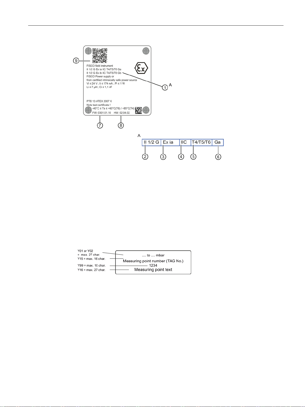
Description
①
⑤
ture class)
②
Category of the operating range
⑥
Device protection level
③
Type of protection
⑦
Firmware identifier
④
Group (gas, dust)
⑧
Hardware identifier
⑨
vice-specific information on the product
teristics ①
3.6
Measuring point label layout
3.7
Principle of operation
3.7.1
Overview of mode of operation
3.6 Measuring point label layout
Characteristics of the hazardous area
Maximum surface temperature (tempera-
QR code to the mobile website with de-
Image 3-3 Example of measuring point label
A More detailed information on the charac-
This chapter describes how the pressure transmitter works.
First the electronics are described, and then the physical principle of the sensors which are
used with the various device versions for the individual measurement types.
SITRANS P DS III/P410 with PROFIBUS PA
Operating Instructions, 02/2016, A5E00053276-08
27
Description
3.7.2
Operation of the electronics
Description
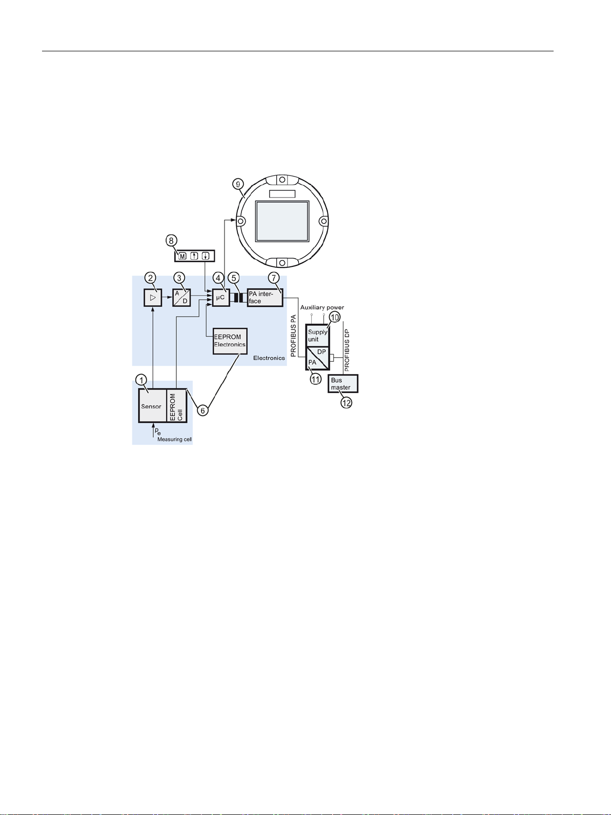
①
Measuring cell sensor
⑧
Buttons (local operation)
②
Measuring amplifier
⑨
Display
③
Analog-to-digital converter
⑩
Power supply
④
Microcontroller
⑪
DP/PA coupler or DP/PA link
⑤
Electrical isolation
⑫
Bus master
⑥
and in the electronics
⑦
PROFIBUS PA interface
Function
3.7 Principle of operation
Each with an EEPROM in the measuring cell
Image 3-4 Principle of operation of the electronics with PA communication
● The inlet pressure is converted into an electrical signal by the sensor
● This signal is amplified by the measuring amplifier
● The digital signal is analyzed in a microcontroller
● The signal is available at an electrically isolated PA interface
converter
and thermal characteristics.
③.
pe Input variable
② and digitized in an analog-to-digital
④ and corrected with regard to linearity
⑦ on the PROFIBUS PA.
①.
SITRANS P DS III/P410 with PROFIBUS PA
28 Operating Instructions, 02/2016, A5E00053276-08

Description
Operation
3.7.3
Principle of operation of the measuring cell
WARNING
Destruction of the seal diaphragm
Overview
3.7 Principle of operation
● The data specific to the measuring cell, the electronics data, and the parameterization
data are stored in two EEPROMs
the second with the electronics.
● The results with the status values and diagnostics data are transmitted cyclically over the
PROFIBUS PA. Parameterization data and error messages are transmitted acyclically by
SIMATIC PDM.
⑥. The first memory is linked with the measuring cell,
● The buttons
● If you have a display
Danger of injury or damage to device
If the seal membrane is destroyed, the sensor may also be destroyed. If the seal
membrane is destroyed, no reliable measured values can be output.
Hot, toxic and corrosive process media can be released.
• Ensure that the material of the device parts wetted by the process medium is suitable for
• Make sure that the device is suitable for the maximum operating pressure of your
• Define maintenance intervals for regular inspections in line with device use and
⑧ can be used to call up individual functions, so-called modes.
⑨, you can track the mode settings and other messages on it.
the medium. Refer to the information in Technical data (Page 193).
system. Refer to the information on the nameplate and/or in Technical data (Page 193).
empirical values. The maintenance intervals will vary from site to site depending on
corrosion resistance.
In the following sections, the process variable to be measured is called general inlet
pressure.
The following modes of operation are described:
● Gauge pressure
● Absolute pressure
SITRANS P DS III/P410 with PROFIBUS PA
Operating Instructions, 02/2016, A5E00053276-08
● Differential pressure and flow rate
● Level
The following process connections are available, for example:
● G1/2 B, 1/2-14 NPT
● Male thread: M20
29
Description
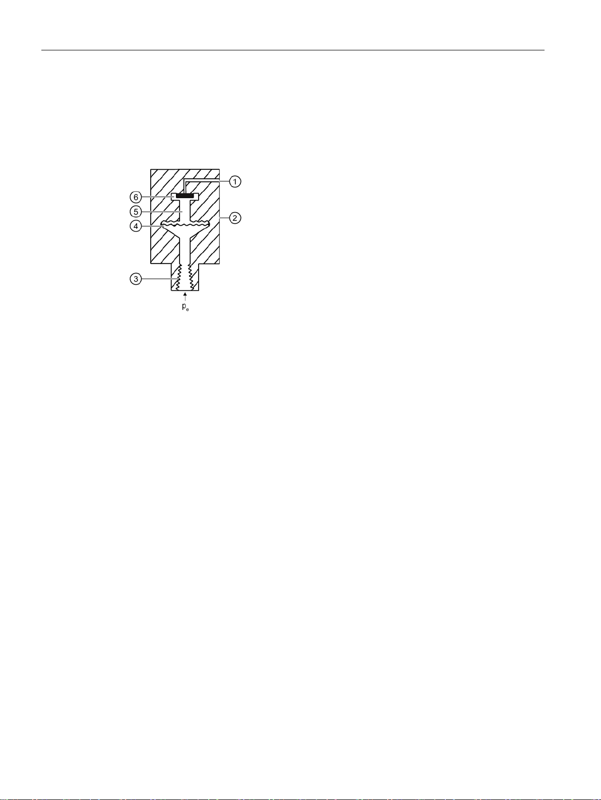
3.7.3.1
Measuring cell for gauge pressure
①
Reference pressure opening
⑤
Filling liquid
②
Measuring cell
⑥
Gauge pressure sensor
③
Process connection
pe
Inlet pressure
④
Seal diaphragm
3.7 Principle of operation
● Flange connection in accordance with EN 61518
● Flush-mounted process connections
Image 3-5 Function chart of measuring cell for gauge pressure
The inlet pressure (pe) is transferred to the gauge pressure sensor ⑥ via the seal diaphragm
④ and the fill fluid ⑤, displacing its measuring diaphragm. The displacement changes the
resistance of the four piezoresistors (bridge circuit) of the gauge pressure sensor. The
change in the resistance causes a bridge output voltage proportional to the inlet pressure.
Pressure transmitters with spans ≤ 6.3 MPa measure the inlet pressure against atmosphere,
those with spans ≥ 16 MPa the inlet pressure against vacuum.
SITRANS P DS III/P410 with PROFIBUS PA
30 Operating Instructions, 02/2016, A5E00053276-08
 Loading...