

Siemens SITRANS P200, 7MF1565 Series Operating Instructions Manual
Pressure transmitter
SITRANS P200 (7MF1565)
Operating Instructions
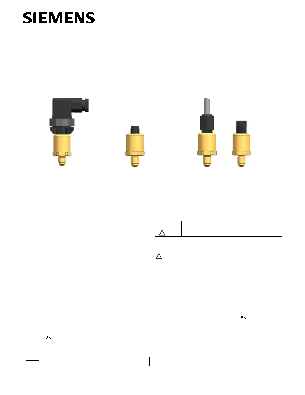
7MF1565 with plug complying with EN 175301-803-A
Type 7MF1565-*****-1**1
Type 7MF1565-*****-5**1
7MF1565 with plug M12x1
Type 7MF1565-*****-2**1
7MF1565 with cable (2 m)
Type 7MF1565-*****-3**1
7MF1565 with fast-fit cable gland
Type 7MF1565-*****-4**1
Range of application SITRANS P200, type 7MF1565
The pressure transmitter is used to measure relative pressure and
absolute pressure of gases and liquids in the following
industrial sectors:
Mechanical engineering Shipbuilding
Power engineering Chemicals
Water supply Pharmaceuticals
Device design without explosion protection
The pressure transmitter consists of a piezoresistive measuring cell with a
diaphragm, installed in a stainless steel housing. It can be electrically connected
using a plug complying with EN 175301-803-A (IP65), a round plug M12 (IP67),
a cable (IP67) or a fast-fit cable gland (IP67). The output signal is 4 to 20 mA or
0 to 10 V.
Device design with explosion protection
The pressure transmitter consists of a piezoresistive measuring cell with a diaphragm, installed in a stainless steel housing. It can be electrically connected with
a plug complying with EN 175301-803-A (IP65) or a round plug M12 (IP67). The
output signal is 4 to 20 mA.
Installation
The location of the device has no influence on the precision of the measure-
ment.
Before installation, compare the process data with the data of the name plate.
The medium being measured must be suitable for the parts of the pressure
transmitter in contact with the medium.
The overload limit must not be exceeded.
Connect the devices to a fixed cable installation.
Grounding for devices
The pressure transmitter must be connected to the equipotential bonding system
of the plant via the metal housing (process connection) and the ground conductor of the plug.
Direct current
Safety instructions
Symbol Explanation of the warning symbol on the device
Read the information in the operating instructions
In terms of a safety-instrumented system, this device left the factory in perfect
condition. To maintain this status and to ensure safe operation of the device,
observe the following notes:
The device may only be used for the purposes specified in these instructions.
When connecting up, installing and operating the device, the directives and
laws of your country apply.
Devices with the type of protection "intrinsic safety„ lose their approval, if they
are operated on electrical circuits that do not conform to the test certification
valid for your country.
Connect the device to a low voltage power supply with safe separation (SELV).
The device should only be supplied with limited energy according to UL 61010-1
Second Edition, Section 9.3 or LPS in conformance with UL 60950-1 or class 2 in
compliance with UL 1310 or UL 1585.
The device can be operated both at high pressure and with aggressive and
hazardous media. This means that if the device is not used properly, serious
bodily injury and/or considerable damage to property cannot be excluded. This
should be kept in mind particularly when the device was in use and is replaced.
The installation, mounting and commissioning of the devices should be
performed only by trained personnel and should comply with the standards
EN 60079-14 and EN 61241-14.
The overload limit should be monitored and kept to at all times.
The device is maintenance-free
© Siemens 2011
A5E03304326-01, 03/2011
© Siemens AG 2011
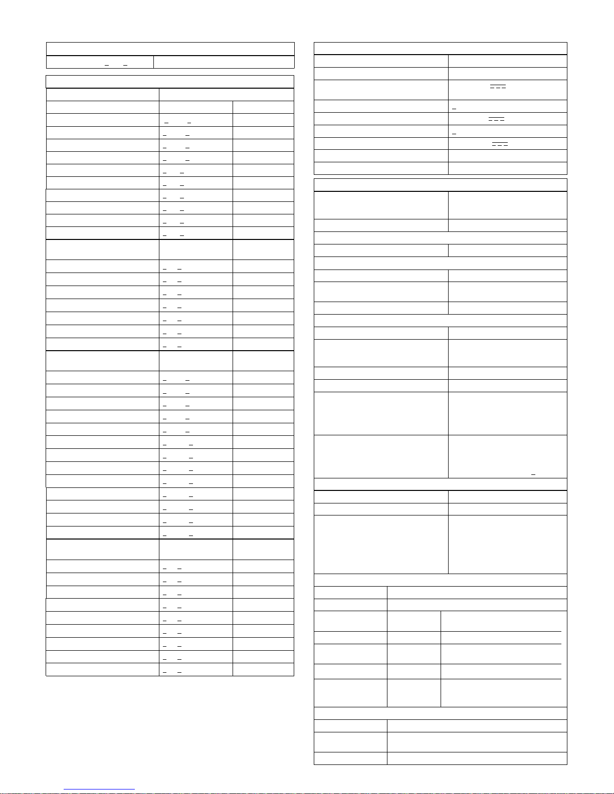
Technical data
SITRANS P200 (7MF1565)
A5E03304326-01, 03/2011
Mode of operation
Measuring range > 1 ... < 60 bar Piezoresistive with ceramic diaphragm
Input
Measured variable input
Measuring range for gauge pressure Overload limit Burst pressure
0 ... 1 bar g
> -0.4 / < 2.5 bar g > 2.5 bar
0 ... 1.6 bar g
> -0.4 / < 4 bar g > 4 bar
0 ... 2.5 bar g
> -0.8 / < 6.25 bar g > 6.25 bar
0 ... 4 bar g
> -0.8 / < 10 bar g > 10 bar
0 ... 6 bar g
> -1 / < 15 bar g > 15 bar
0 ... 10 bar g
> -1 / < 25 bar g > 25 bar
0 ... 16 bar g
> -1 / < 40 bar g > 40 bar
0 ... 25 bar g
> -1 / < 62.5 bar g > 62.5 bar
0 ... 40 bar g
> -1 / < 100 bar g > 100 bar
0 ... 60 bar g
> -1 / < 150 bar g > 150 bar
Measuring range for absolute
pressure
Overload limit Burst pressure
0 ... 1 bar a
> 0 / < 2.5 bar a > 2.5 bar
0 ... 1.6 bar a
> 0 / < 4 bar a > 4 bar
0 ... 2.5 bar a
> 0 / < 6.25 bar a > 6.25 bar
0 ... 4 bar a
> 0 / < 10 bar a > 10 bar
0 ... 6 bar a
> 0 / < 15 bar a > 15 bar
0 ... 10 bar a
> 0 / < 25 bar a > 25 bar
0 ... 16 bar a
> 0 / < 40 bar a > 40 bar
Measuring range for gauge
pressure (for US market only)
Overload limit Burst pressure
0 ... 10 psi g
> -5.8 / < 35 psi g > 35 psi
0 ... 15 psi g
> -5.8 / < 35 psi g > 35 psi
3 ... 15 psi g
> -5.8 / < 35 psi g > 35 psi
0 ... 20 psi g
> -5.8 / < 50 psi g > 50 psi
0 ... 30 psi g
> -5.8 / < 80 psi g > 80 psi
0 ... 60 psi g
> -11.5 / < 140 psi g > 140 psi
0 ... 100 psi g
> -14.5 / < 200 psi g > 200 psi
0 ... 150 psi g
> -14.5 / < 350 psi g > 350 psi
0 ... 200 psi g
> -14.5 / < 550 psi g > 550 psi
0 ... 300 psi g
> -14.5 / < 800 psi g > 800 psi
0 ... 500 psi g
> -14.5 / < 1 400 psi g > 1 400 psi
0 ... 750 psi g
> -14.5 / < 2 000 psi g > 2 000 psi
0 ... 1 000 psi g
> -14.5 / < 2 000 psi g > 2 000 psi
Measuring range for absolute
pressure
(for US market only)
Overload limit Burst pressure
0 ... 10 psi a
> 0 / < 35 psi a > 35 psi
0 ... 15 psi a
> 0 / < 35 psi a > 35 psi
0 ... 20 psi a
> 0 / < 50 psi a > 50 psi
0 ... 30 psi a
> 0 / < 80 psi a > 80 psi
0 ... 60 psi a
> 0 / < 140 psi a > 140 psi
0 ... 100 psi a
> 0 / < 200 psi a > 200 psi
0 ... 150 psi a
> 0 / < 350 psi a > 350 psi
0 ... 200 psi a
> 0 / < 550 psi a > 550 psi
0 ... 300 psi a
> 0 / < 800 psi a > 800 psi
Output
Current signal 4 ... 20 mA
Burden (U
B
- 10 V) / 0.02 A
Auxiliary power U
B
DC 7 ... 33 V (10 to 30 V for
hazardous areas)
Current consumption I
B
< 20 mA
Voltage signal 0 ... 10 VDC
Burden > 10 kΩ
Auxiliary power U
B
12 ... 33 VDC
Current consumption < 7 mA at 10 kΩ
Characteristic Linear rising
Measuring accuracy
Measurement deviation at 25 ÀC (77 ÀF),
Characteristic deviation, hysteresis and
repeatability included
typically: 0.25 % of full scale value
maximum: 0.5 % of full scale value
Setting T99 < 0.1 s
Long-term drift
Start-of-scale value and measuring span 0.25 % of full scale value/year
Ambient temperature influence
Start-of-scale value and measuring span
0.25 %/10 K of full-scale value
Vibration influence (complying with IEC
60068-2-6)
0.005 %/g to 500 Hz in all
directions
Auxiliary power influence 0.005 %/V
Conditions during operation
Ambient air temperature -25 ⁄ +85 ÀC (-13 to +185 ÀF)
Altitude max. 2 000 m ASL
Use an appropriate power supply for
altitudes higher than 2000 m ASL.
Relative humidity 0 ... 100 %
Storage temperature -50 ⁄ +100 ÀC (-58 to +212 ÀF)
Degree of protection (complying with
EN 60529)
IP65 with plug complying with
EN 175301-803-A
IP67 with M12 plug
IP67 with cable
IP67 with cable fast-fit gland
Electromagnetic compatibility
complying with EN 61326-1
complying with EN 61326-2-3
complying with NAMUR NE21, only
for ATEX device and max. measured value deviation of < 1 %
Construction
Weight approx. 0.090 kg (0.198 lb)
Process connections Dimension drawings
Electrical connections
Plug complying with EN 175301-
803-A Form A with cable inlet
M16x1.5 or -14NPT or Pg 11
M12 plug
2- or 3-wire (0.5 mm
2
)
Cable (± 5.4 mm)
Fast-fit cable gland
Material of the parts in contact with measured material
Measuring cell AI
2O3
- 96 %
Process connection stainless steel, material no. 1.4404 (SST 316 L)
Material of parts not in contact with the medium
Housing stainless steel, material no. 1.4404 (SST 316 L)
Pin and socket plastic
connector housing CuZn, nickel-plated (plug M12)
Cable PVC spec.
Sealing material
Position 15 of
order number
Media temperature
Viton (FPM) A -15 ... +125 ÀC (+5 ⁄ +257ÀF)
Neoprene (CR) B -35 ... +100 ÀC < 100 bar
(-31 ⁄ +212 ÀF; < 1 450 psi)
Perbunan (NBR) C -20 ... +100 ÀC (-4 ⁄ +212 ÀF)
EPDM D -40 ... +145 ÀC < 100 bar
(-40 ⁄ +293 ÀF; < 1 450 psi),
can be used for drinking water
© Siemens AG 2011
 Loading...