

Siemens SITRANS F M MAG 1100, SITRANS F, SITRANS MAG 1100 HT, 7ME614, SITRANS MAG 1100 F Operating Instructions Manual
...
Electromagnetic Flowmeters
SITRANS F M MAG 1100 sensor
Electromagnetic flow sensor designed for use with
transmitter types SITRANS F M MAG 5000 / 6000 and
MAG 6000 I
Introduction
1
Operating Instructions
Safety notes
Description
Installing/Mounting
Connecting
Service and maintenance
Troubleshooting
Technical data
2
3
4
5
6
7
8
Appendix
A
01/2018
A5E03433301-AC
Legal information
Warning notice system
This manual contains notices you have to observe in order to ensure your personal safety, as well as to prevent
damage to property. The notices referring to your personal safety are highlighted in the manual by a safety alert
symbol, notices referring only to property damage have no safety alert symbol. These notices shown below are
graded according to the degree of danger.
DANGER
indicates that death or severe personal injury will result if proper precautions are not taken.
WARNING
indicates that death or severe personal injury may result if proper precautions are not taken.
CAUTION
indicates that minor personal injury can result if proper precautions are not taken.
NOTICE
indicates that property damage can result if proper precautions are not taken.
If more than one degree of danger is present, the warning notice representing the highest degree of danger will be
used. A notice warning of injury to persons with a safety alert symbol may also include a warning relating to property
damage.
Qualified Personnel
The product/system described in this documentation may be operated only by personnel qualified for the specific
task in accordance with the relevant documentation, in particular its warning notices and safety instructions. Qualified
personnel are those who, based on their training and experience, are capable of identifying risks and avoiding
potential hazards when working with these products/systems.
Proper use of Siemens products
Note the following:
WARNING
Siemens products may only be used for the applications described in the catalog and in the relevant technical
documentation. If products and components from other manufacturers are used, these must be recommended or
approved by Siemens. Proper transport, storage, installation, assembly, commissioning, operation and
maintenance are required to ensure that the products operate safely and without any problems. The permissible
ambient conditions must be complied with. The information in the relevant documentation must be observed.
Trademarks
All names identified by ® are registered trademarks of Siemens AG. The remaining trademarks in this publication
may be trademarks whose use by third parties for their own purposes could violate the rights of the owner.
Disclaimer of Liability
We have reviewed the contents of this publication to ensure consistency with the hardware and software described.
Since variance cannot be precluded entirely, we cannot guarantee full consistency. However, the information in
this publication is reviewed regularly and any necessary corrections are included in subsequent editions.
Siemens AG
Division Process Industries and Drives
Postfach 48 48
90026 NÜRNBERG
GERMANY
Document order number: A5E03433301
Ⓟ 01/2018 Subject to change
Copyright © Siemens AG 2018.
All rights reserved

Table of contents
1 Introduction...................................................................................................................................................5
1.1 Items supplied..........................................................................................................................5
1.2 Device identification.................................................................................................................5
1.3 History......................................................................................................................................6
1.4 Further Information...................................................................................................................7
2 Safety notes..................................................................................................................................................9
2.1 Laws and directives..................................................................................................................9
2.2 Installation in hazardous area................................................................................................11
2.3 Certificates.............................................................................................................................13
3 Description..................................................................................................................................................15
3.1 Applications............................................................................................................................15
3.2 System components...............................................................................................................15
3.3 Design....................................................................................................................................16
3.4 Theory of operation................................................................................................................17
4 Installing/Mounting......................................................................................................................................19
4.1 Installation safety precautions................................................................................................19
4.2 Determining a location...........................................................................................................20
4.3 Installation in partially filled pipes...........................................................................................21
4.4 Orienting the sensor...............................................................................................................23
4.5 Mounting MAG 1100/1100 HT...............................................................................................24
4.6 Mounting MAG 1100 F...........................................................................................................27
4.6.1 Mounting with a welding type adapter....................................................................................29
4.6.2 Mounting with a clamp type adapter......................................................................................29
4.6.3 Mounting with a threaded type adapter..................................................................................30
4.7 Torques values.......................................................................................................................30
4.8 Potential equalization.............................................................................................................31
5 Connecting.................................................................................................................................................33
5.1 General safety requirements..................................................................................................33
5.2 Remote installation.................................................................................................................35
5.3 Installation check....................................................................................................................38
5.4 Potting....................................................................................................................................39
SITRANS F M MAG 1100 sensor
Operating Instructions, 01/2018, A5E03433301-AC 3

Table of contents
6 Service and maintenance...........................................................................................................................41
6.1 Maintenance...........................................................................................................................41
6.2 Recalibration..........................................................................................................................41
6.3 Unit repair...............................................................................................................................41
6.4 Technical support...................................................................................................................42
6.5 Return procedures.................................................................................................................42
6.6 Disposal.................................................................................................................................43
7 Troubleshooting..........................................................................................................................................45
7.1 Improving the application.......................................................................................................45
7.2 Sensor check.........................................................................................................................45
7.3 Fluctuating process values.....................................................................................................47
8 Technical data............................................................................................................................................49
8.1 Process connections..............................................................................................................49
8.2 Rated operating conditions....................................................................................................50
8.3 Temperature shock................................................................................................................50
8.4 Design....................................................................................................................................52
8.5 Liner.......................................................................................................................................52
8.6 Electrodes..............................................................................................................................53
8.7 Cable entries..........................................................................................................................53
8.8 Pressure / temperature range................................................................................................54
8.9 Process fluid conductivity.......................................................................................................55
8.10 Dimensions and weight..........................................................................................................56
8.11 Accessories for MAG 1100 F.................................................................................................59
8.12 Certificates and approvals......................................................................................................62
A Appendix.....................................................................................................................................................65
A.1 Factory settings......................................................................................................................65
A.2 Coil resistance........................................................................................................................66
A.3 Ordering of spare parts..........................................................................................................67
Index...........................................................................................................................................................69
SITRANS F M MAG 1100 sensor
4 Operating Instructions, 01/2018, A5E03433301-AC

Introduction
These instructions contain all the information you need for using the device.
The instructions are aimed at persons mechanically installing the device, connecting it
electrically, configuring the parameters and commissioning it, as well as service and
maintenance engineers.
Note
It is the responsibility of the customer that the instructions and directions provided in the
operating instructions are read, understood, and followed by the relevant personnel before
installing the device.
1.1 Items supplied
● SITRANS F M MAG 1100
● Calibration report
● SITRANS F M literature CD
● Quick Start guide
1
1.2 Device identification
Inspection
1. Check for mechanical damage due to possible improper handling during shipment. All
claims for damage are to be made promptly to the shipper.
2. Make sure the scope of delivery, and the information on the type plate correspond to the
ordering information
SITRANS F M MAG 1100 sensor
Operating Instructions, 01/2018, A5E03433301-AC 5
1
7
8
2
3
4
5
6
9
1
2
Introduction
1.3 History
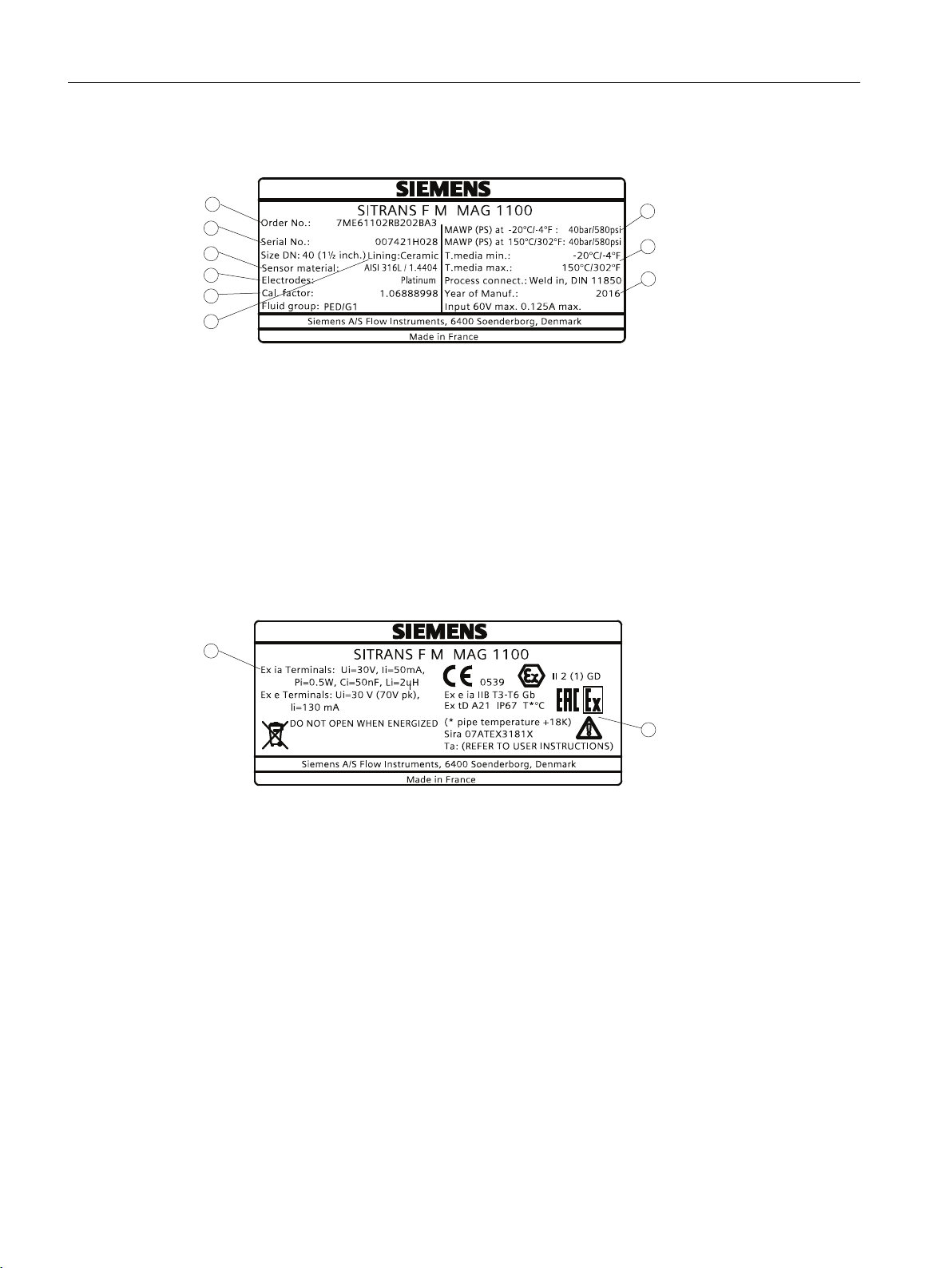
Identification
① Product name Sensor product name
② System order no. Device-specific system order number
③ Material Sensor material
④ Cal. Factor Calibration factor
⑤ Fluid group Fluid group statement required by PED
⑥ Lining Liner type Ceramic
⑦ MAWP Maximum allowable working pressures at -20 °C (-4 °F) and 150
°C (302 °F)
⑧ Tmedia Process media temperature
⑨ Year of Manufacture Manufacturing year
Figure 1-1 MAG 1100 identification nameplate example
① Intrinsical safety data
② Ex approvals Ex approval specifications for the sensor
Figure 1-2 MAG 1100 Ex identification nameplate example
1.3 History
The contents of these instructions are regularly reviewed and corrections are included in
subsequent editions. We welcome all suggestions for improvement.
6 Operating Instructions, 01/2018, A5E03433301-AC
SITRANS F M MAG 1100 sensor

The following table shows the most important changes in the documentation compared to each
previous edition.
Edition Remarks
02/2011 First edition
The Operating Instructions replaces:
● MAG 1100 part of SITRANS F M HANDBOOK (A5E02435647)
● SITRANS F M MAG 1100 DN 2- DN 100
● SITRANS F M MAG 1100 DN 2- DN 3
05/2016 Updated connecting/remote installation
Updated dimension-dependent factory settings
Updated coil resistance table
1.4 Further Information
Product information on the Internet
Introduction
1.4 Further Information
The Operating Instructions are available on the documentation disk shipped with the device,
and on the Internet on the Siemens homepage, where further information on the range of
SITRANS F flowmeters may also be found:
Local contact person (http://www.automation.siemens.com/partner)
Worldwide contact person
If you need more information or have particular problems not covered sufficiently by these
Operating Instructions, get in touch with your contact person. You can find contact information
for your local contact person on the Internet:
Product information on the internet (http://www.siemens.com/flow)
See also
Technical support (Page 42)
SITRANS F M MAG 1100 sensor
Operating Instructions, 01/2018, A5E03433301-AC 7

Introduction
1.4 Further Information
SITRANS F M MAG 1100 sensor
8 Operating Instructions, 01/2018, A5E03433301-AC

Safety notes
CAUTION
Correct, reliable operation of the product requires proper transport, storage, positioning and
assembly as well as careful operation and maintenance.
Only qualified personnel should install or operate this instrument.
Note
Alterations to the product, including opening or improper modifications of the product are not
permitted.
If this requirement is not observed, the CE mark and the manufacturer's warranty will expire.
2.1 Laws and directives
General requirements
2
Installation of the equipment must comply with national regulations. For example EN 60079-14
for the European Community.
Instrument safety standards
The device has been tested at the factory, based on the safety requirements. In order to
maintain this condition over the expected life of the device the requirements described in these
Operating Instructions must be observed.
NOTICE
Material compatibility
Siemens Flow Instruments can provide assistance with the selection of wetted sensor parts.
However, the full responsibility for the selection rests with the customer and Siemens Flow
Instruments can take no responsibility for any failure due to material incompatibility.
CE marked equipment
The CE-mark symbolizes the compliance of the device with the following directives:
● EMC-directive 89/336/EWG
● Low voltage directive 73/23/EWG
SITRANS F M MAG 1100 sensor
Operating Instructions, 01/2018, A5E03433301-AC 9
Safety notes
2.1 Laws and directives
● Pressure equipment directive (PED/DGRL) 93/23/EG
● ATEX Directive 94/9/EG
PED directive
Pressure Equipment Directive" (PED) is mandatory for all pressure equipment sold within the
EU and EFTA.
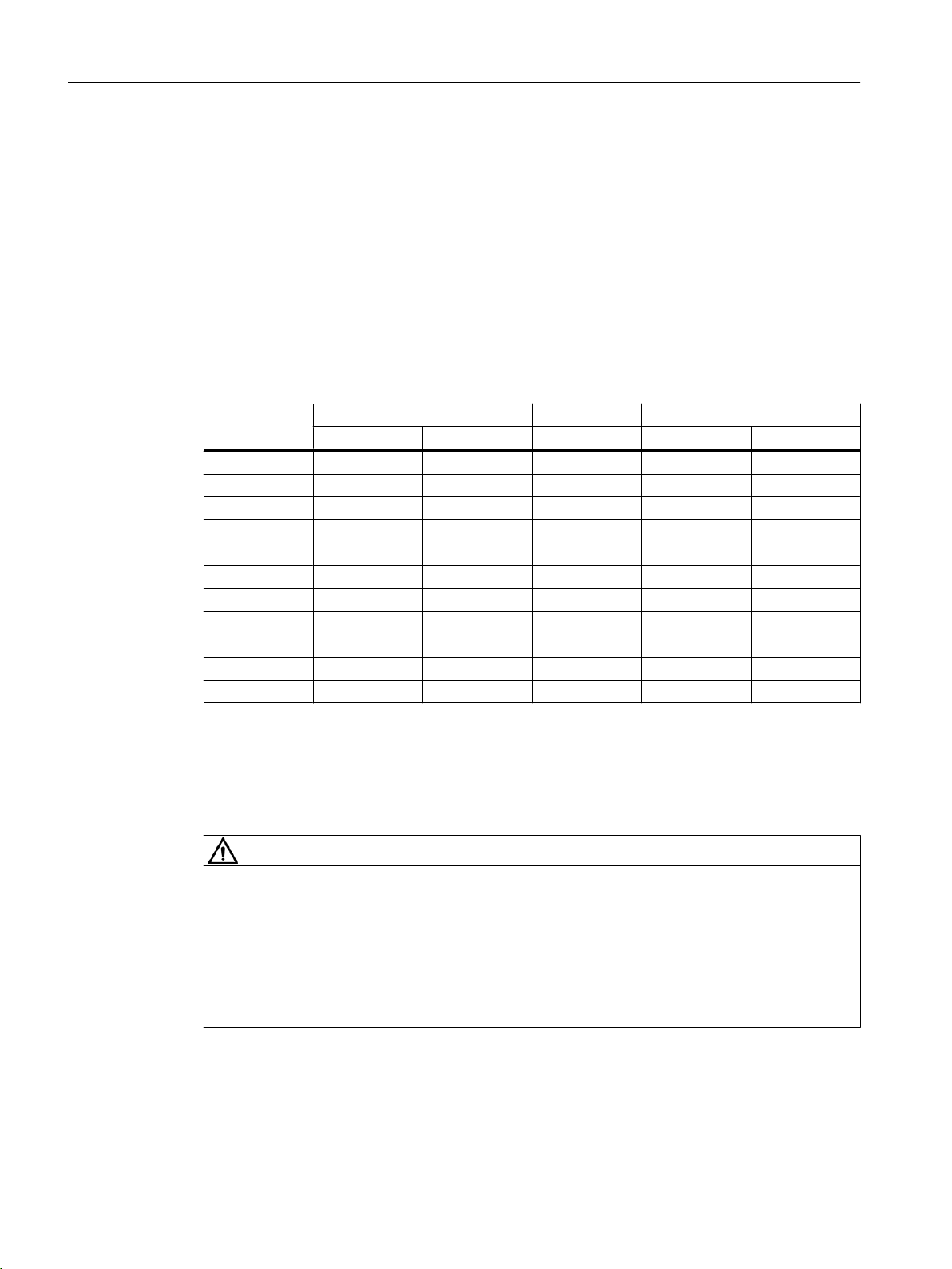
Siemens Flow Instruments products comply with PED as stated in the following table.
Table 2-1 MAG 1100 and MAG 1100 HT PED compliance
Flange
mm
2 EXC.PED N/A N/A N/A N/A
3 EXC.PED N/A N/A N/A N/A
6 EXC.PED N/A N/A N/A N/A
10 EXC.PED EXC.PED N/A EXC.PED EXC.PED
15 EXC.PED EXC.PED EXC.PED EXC.PED EXC.PED
25 EXC.PED EXC.PED EXC.PED EXC.PED EXC.PED
40 PED EXC.PED PED PED EXC.PED
50 PED PED PED PED PED
65 PED PED PED PED PED
80 PED PED PED PED PED
100 PED PED PED PED PED
Siemens Flow Instruments products confirms to PED by following the tables below.
MAG 1100 MAG 1100 HT MAG 1100 F
Ceramic PFA Ceramic Ceramic PFA
EXC. PED = Excluded from PED under SEP or LVD
PED= Product covered by PED
N/A= Size/pressure outside of PED scope or not available in the size range
CAUTION
All products sold outside of EU and EFTA are excluded from the Pressure Equipment
directive, also products sold into certain market sectors are excluded. These include
1. Meters used in networks for the supply, distribution and discharge of water.
2. Meters used in pipelines for the conveyance of any fluid from offshore to onshore.
3. Meters used in the extraction of petroleum or gas, including christmas tree and manifold
equipment.
4. Any meter mounted on a ship or mobile offshore platform.
SITRANS F M MAG 1100 sensor
10 Operating Instructions, 01/2018, A5E03433301-AC
2.2 Installation in hazardous area
WARNING
Equipment used in hazardous areas must be Ex-approved and marked accordingly.
It is required that the special conditions for safe use provided in the manual and in the Ex
certificate are followed!
Hazardous area approvals
The device is approved for use in hazardous area and has the following approval:
● II 2 (1) GD Ex e ia IIB T3-T6 (MAG 1100 Ex remote mounted)
● II 2 (1) (2) GD Ex d [ia] [ib] IIB T3-T6 (MAG 1100 Ex compact mounted with MAG 6000 I Ex
de)
WARNING
Safety notes
2.2 Installation in hazardous area
Make sure the hazardous area approval is suitable for the environment in which the device
will be installed.
Intrinsically safe data
Table 2-2 Intrinsically safe data for remote mounted MAG 1100 Ex
Coil circuit "Ex e" (Terminal 85,86)
Ui 30 V (70 V peak)
Ii 130 mA
Compact mounted versions
For intrinsically safe data for MAG 3100 Ex compact mounted with MAG 6000 I Ex d, refer
to the Operating Instructions of MAG 6000 I or to certificate number Sira 07ATEX3181X,
available here: Sira certificate (https://support.industry.siemens.com/cs/document/43032182/
for-use-in-hazardous-locations-atex-ec-type-examination-certificate-sira?
dti=0&pnid=17323&lc=en-WW).
WARNING
WARNING
With intrinsically safe circuits, use only certified meters appropriate for the transmitter.
If a non-conforming supply unit is used, the "fail-safe" type of protection will no longer be
effective and the approval certification will be invalid.
SITRANS F M MAG 1100 sensor
Operating Instructions, 01/2018, A5E03433301-AC 11

Safety notes
2.2 Installation in hazardous area
Temperature specifications for Ex use
Maximum process fluid tempera‐
ture [°C]
67 T6 (85 °C) -25 to +60
82 T5 (100 °C) -25 to +60
117 T4 (135 °C) -25 to +60
180 (Remote configuration) T3 (200 °C) -25 to +60
150 (Compact configuration) T3 (200 °C) -25 to +50
For dust protection, the surface temperature is equal to the process fluid temperature plus 5 °C
Special conditions for safe use
It is required that:
Electrical connections are in accordance with IEC/EN60079-14 (Installing Electrical Systems
in Explosion Hazardous Areas).
● The protective cover over the power supply is properly installed. For intrinsically safe circuits
the connection area can be opened.
● Appropriate cable connectors are used for the output circuits:
– Intrinsically safe: blue
– Non-intrinsically safe: black
● Sensor and transmitter are connected to the potential equalization.
For intrinsically safe output circuits potential equalization must be maintained along the
entire connection path.
Maximum process fluid tempera‐
ture [°C]
Ambient temperature [°C]
● Sensor insulation thickness is max. 100 mm (only insulated sensors).
● EN50281-1-2 is considered for installation in areas with combustible dust.
● When protective earth (PE) is connected, no potential difference between the protective
earth (PE) and the potential equalization (PA) can exist, even during a fault condition.
WARNING
"Flameproof enclosure" type of protection
Only open devices with type of protection "Flameproof enclosure" in hazardous areas
when the power to the device is turned off, otherwise there is a risk of explosion.
WARNING
Laying of cables
Cable for use in zone 1 and 2 or 21 and 22 must satisfy the requirements for having a
proof voltage < AC 500 V applied between the conductor/ground, conductor/shield and
shield/ground.
Connect the devices that are operated in hazardous areas as per the stipulations
applicable in the country of operation, e.g. for Ex "d" and "nA", permanent cables must be
laid.
SITRANS F M MAG 1100 sensor
12 Operating Instructions, 01/2018, A5E03433301-AC

2.3 Certificates
You can find certificates on the Internet at online support portal (http://www.siemens.com/
processinstrumentation/certificates) or on an included DVD.
See also
Technical data (Page 49)
Safety notes
2.3 Certificates
SITRANS F M MAG 1100 sensor
Operating Instructions, 01/2018, A5E03433301-AC 13

Safety notes
2.3 Certificates
SITRANS F M MAG 1100 sensor
14 Operating Instructions, 01/2018, A5E03433301-AC
Description
3.1 Applications
The pulsed DC-powered magnetic flowmeters are suitable for measuring the flow of almost all
electrically conductive liquids, pastes, and slurries with max. 40% solids.
The main applications can be found in the following sectors:
● Water and waste water
● Chemical and pharmaceutical industries
● Food & beverage industry
● Mining and cements industries
● Pulp and paper industry
● Steel industry
● Power generation; utility and chilled water industry
WARNING
This is a Class A product
3
In a domestic environment this product may cause radio interference in which case the user
may be required to take adequate measures.
3.2 System components
The SITRANS F M flowmeter system includes:
● Transmitter (types: SITRANS F M MAG 5000/6000 or MAG 6000 I)
● Sensor (types: SITRANS F M MAG 1100/1100 F, MAG 3100/3100 P or MAG 5100 W)
● Communication module (optional) (types: HART, PROFIBUS PA/DP, MODBUS RTU RS
485, Foundation Fieldbus H1, Devicenet)
● SENSORPROM memory unit
Communication solutions
The SITRANS F M range of add-on modules, presently including HART, Foundation Fieldbus.
MODBUS RTU RS 485, PROFIBUS PA / DP and Devicenet, are all applicable with the
SITRANS F M MAG 6000 transmitter.
SITRANS F M MAG 1100 sensor
Operating Instructions, 01/2018, A5E03433301-AC 15
Description
3.3 Design
3.3 Design
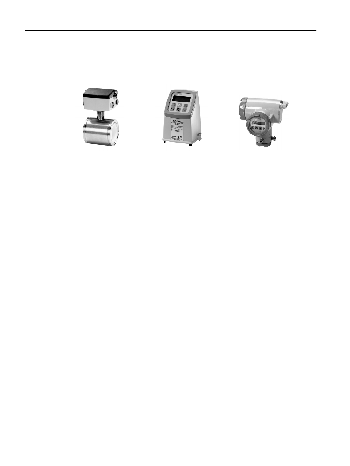
The SITRANS F M MAG 1100 is an electromagnetic flow sensor in a compact wafer design
designed for flow applications in the process industry.
MAG 1100 MAG 5000 MAG 6000I
Sensor housing and flanges are designed in carbon steel (ASTM A 105) and terminal box in
fibre glass reinforced polyamide or optionally in stainless steel (AISI 316). Measuring pipe is
made of stainless steel (AISI 304) while liners and electrodes are available in various materials,
making the sensor highly resistant to a wide range of chemicals.
The present range of liner types includes:
● PFA
● Ceramic
● EPDM
Electrodes are available in:
● Hastelloy C276 or C22
● AISI 316 / 1.4571
● Platinum / platinium with gold/Titanium brazing alloy
The sensors carry a wide range of approvals, see Technical data (Page 49).
SITRANS F M MAG 1100 sensor
16 Operating Instructions, 01/2018, A5E03433301-AC
3.4 Theory of operation
0DJQHWLF)LHOG
)ORZ
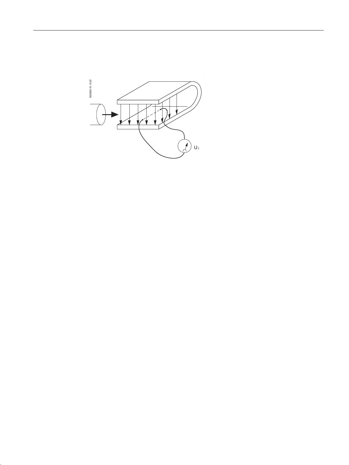
The flow measuring principle is based on Faraday’s law of electromagnetic induction.
Ui = When an electrical conductor of length L is moved at velocity v, perpendicular to the lines
of flux through a magnetic field of strength B, the voltage Ui is induced at the ends of the
conductor
Description
3.4 Theory of operation
Operating principle
Ui = L x B x v
● Ui = Induced voltage
● L = Conductor length = Inner pipe diameter = k
● B = Magnetic field strength = k
2
1
● v = Velocity of conductor (media)
● k = k1 x k
2
Ui = k x v, the electrode signal is directly proportional to the fluid velocity
The coil current module generates a pulsating magnetizing current that drives the coils in the
sensor. The current is permanently monitored and corrected. Errors or cable faults are
registered by the self-monitoring circuit.
The input circuit amplifies the flow-proportional induced voltage signal from the electrodes.
The input impedance is extremely high: >1014 Ω which allows flow measurements on fluids
with conductivities as low as 5 µS/cm. Measuring errors due to cable capacitance are
eliminated due to active cable screening.
The digital signal processor converts the analog flow signal to a digital signal and suppresses
electrode noise through a digital filter. Inaccuracies in the transmitter as a result of long-term
drift and temperature drift are monitored and continuously compensated for via the selfmonitoring circuit. The analog to digital conversion takes place in an ultra low noise ASIC with
23 bit signal resolution. This has eliminated the need for range switching. The dynamic range
of the transmitter is therefore unsurpassed with a turn down ratio of minimum 3000:1.
SITRANS F M MAG 1100 sensor
Operating Instructions, 01/2018, A5E03433301-AC 17

Description
3.4 Theory of operation
SITRANS F M MAG 1100 sensor
18 Operating Instructions, 01/2018, A5E03433301-AC

Installing/Mounting
SITRANS F flowmeters with minimum IP65/NEMA 4X enclosure rating are suitable for indoor
and outdoor installations.
● Make sure that pressure and temperature specifications indicated on the device nameplate /
label will not be exceeded.
WARNING
Installation in hazardous location
Special requirements apply to the location and interconnection of sensor and transmitter. See
Installation in hazardous area (Page 11)
4.1 Installation safety precautions
WARNING
4
High pressure hazard
In applications with working pressures/media that can be dangerous to people, surroundings,
equipment or others in case of pipe fracture, we recommend that special precautions such
as special placement, shielding or installation of a pressure guard or a safety valve are taken
when the flowmeter is mounted.
Note
Install the sensor in well-supported pipelines in order to support the weight of the flowmeter.
SITRANS F M MAG 1100 sensor
Operating Instructions, 01/2018, A5E03433301-AC 19
Installing/Mounting
4.2 Determining a location
4.2 Determining a location
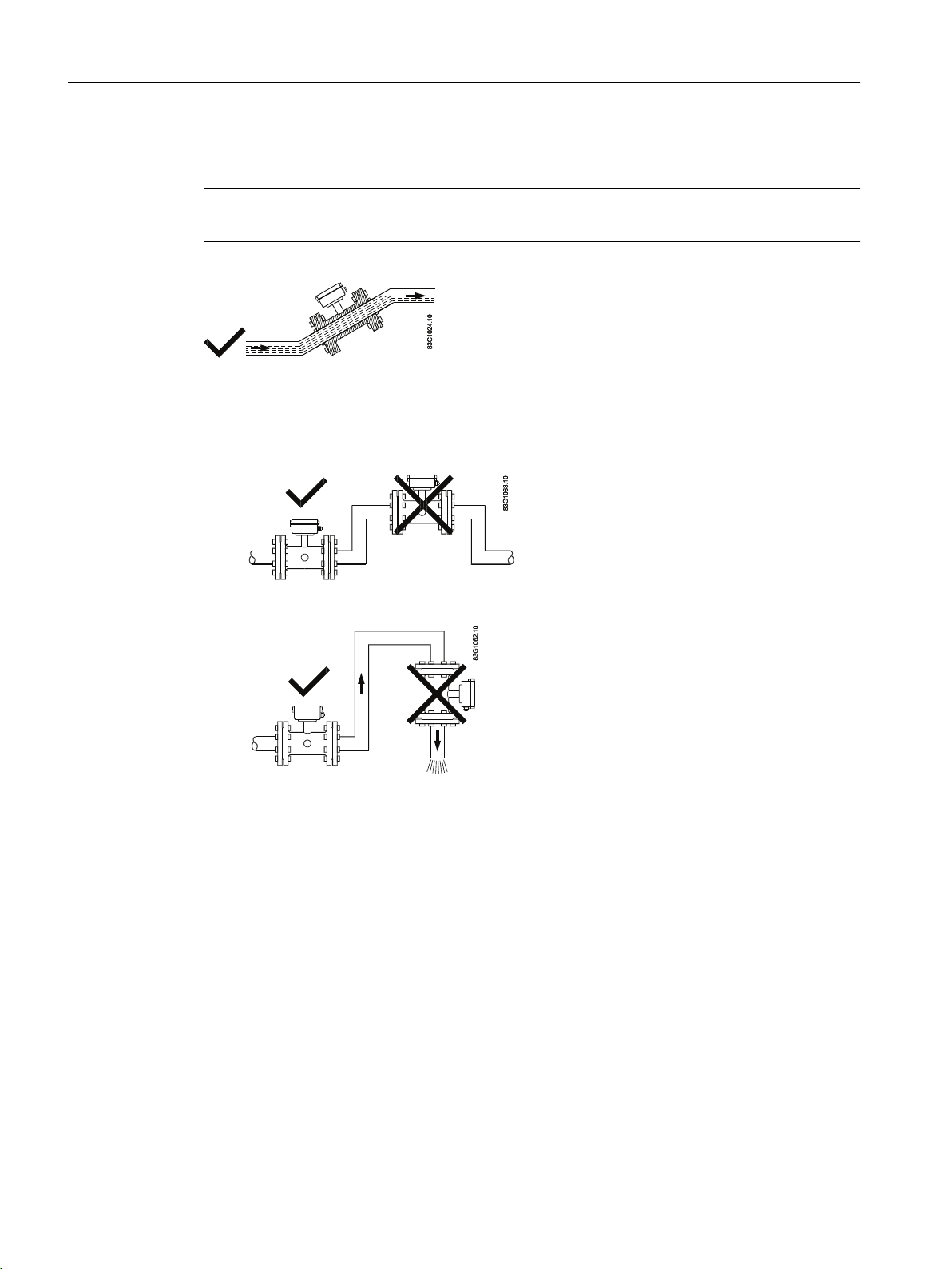
Note
The sensor must always be completely filled with liquid.
Figure 4-1 Correct installation with filled pipes
● Avoid the following installations
– Installation at the highest point in the pipe system
– Installation in vertical pipes with free outlet
Figure 4-2 Wrong installation at high point
Figure 4-3 Correct installation at low point before outlet
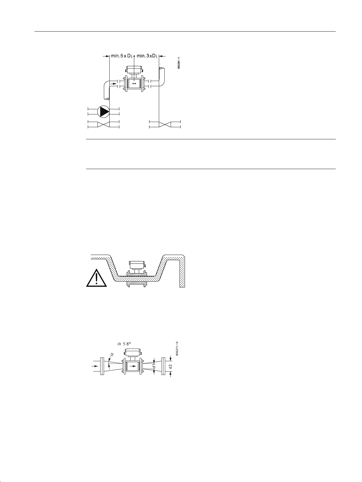
Inlet and outlet conditions
To achieve accurate flow measurement it is essential to have straight lengths of inlet and outlet
pipes and a certain distance to pumps and valves.
It is also important to centre the flowmeter in relation to pipe flanges and gaskets.
SITRANS F M MAG 1100 sensor
20 Operating Instructions, 01/2018, A5E03433301-AC
Installing/Mounting
4.3 Installation in partially filled pipes
Note
Empty pipe detection
For applications with empty pipe detection, the sensor can be tilted 45°, as shown above.
4.3 Installation in partially filled pipes
Installation in partially filled pipes
For partially filled pipes or pipes with downward flow and free outlet the flowmeter should be
located in a U-tube.
Installation in large pipes
The flowmeter can be installed between two reducers (for example DIN 28545). At α ≤ 8° the
following pressure drop curves apply. The curves are applicable to water.
SITRANS F M MAG 1100 sensor
Operating Instructions, 01/2018, A5E03433301-AC 21
 Loading...