

Siemens sitrans LVS200 Instruction Manual
Instruction Manual November 2006
sitrans
sitrans
LVS200
English
Deutsch
Español
Français

Safety Notes
Special attention must be paid to warnings and notes highlighted from the rest of the text
by grey boxes.
WARNING: relates to a caution symbol on the product, and means
that failure to observe the necessary precautions can result in
death, serious injury, and/or considerable material damage.
English
mmmmm
WARNING
1
: means that failure to observe the necessary
precautions can result in death, serious injury, and/or considerable
material damage.
CAUTION: means that failure to observe the necessary precautions can
result in considerable material damage.
Note:
manual.
1.
means important information about the product or that part of the operating
This symbol is used when there is no corresponding caution symbol on the
product.
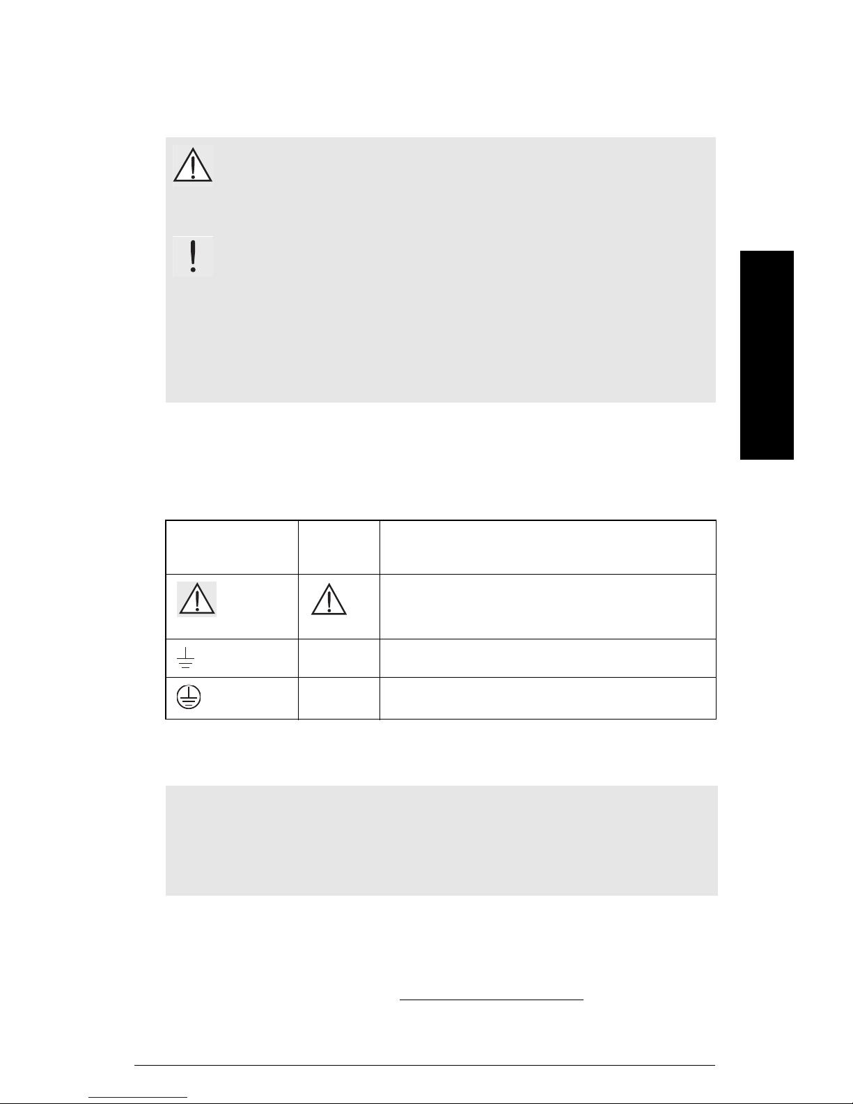
Safety marking symbols
In
Manual
On
Product
Description
(Label on product: yellow background.)
Caution: refer to accompanying documents (manual) for details.
Earth (ground) Terminal
Protective Conductor Terminal
The Manual
Notes:
• Please follow the installation and operating procedures for a quick, trouble-free
installation and to ensure the maximum accuracy and reliability of your SITRANS LVS200
• This manual applies to SITRANS LVS200 only.
This manual will help you set up your SITRANS LVS200 for optimum performance. We
always welcome suggestions and comments about manual content, design, and
accessibility.
Please direct your comments to techpubs.smpi@siemens.com
Siemens Milltronics manuals, go to www.siemens.com/processautomation.
. For the complete library of
7ML19985FT62 SITRANS LVS200 – INSTRUCTION MANUAL Page EN-1

mmmmm
SITRANS LVS200 Introduction
Notes
• Installation, maintenance, and commissioning must be performed by qualified
English
technical personnel.
• SITRANS LVS200 must be used only in the manner outlined in this instruction
manual.
SITRANS LVS200 is available in three versions:
• The SITRANS LVS200, standard version, is a vibrating level switch that detects high
or low levels of dry bulk solids in bins, silos, or hoppers. SITRANS LVS200 provides a
contact output for levels of products such as lime, styrofoam, flour, and plastic
granules. The compact design allows SITRANS LVS200 to be top or side mounted.
The standard length LVS200 fork is also available with variable cable extension
lengths to a maximum of 20 000 mm (787"). An optional longer fork is available for
increased sensitivity. SITRANS LVS200 cable extension is for top mount applications
only. The vibrating fork design ensures that the tines are kept clean.
• The SITRANS LVS200, liquid/solid interface version, is a vibrating level switch that
can also detect settled solids within liquids, or solids within confined spaces such
as feed pipes. This version is designed to ignore liquids in order to detect the
interface between a solid and a liquid. The design incorporates a short fork, and is
also available with variable cable extension lengths to a maximum of 20 000 mm
(787"), for top mount applications only.
• The SITRANS LVS200, pipe extension version, is a vibrating level switch that
incorporates a customer supplied pipe extension [maximum length 3800 mm (150")]
with the standard or liquid/solid (short) LVS200 fork and electronics. This allows for
separation of the electronics and tuning fork for specialized applications. Please
SITRANS LVS200 Pipe Extended Version
see
assembly.
on page 18 for information on
Product Features
• High resistance to mechanical forces
• Strong vibration resistance to high bulk material loads
• Rotatable enclosure
• Stainless steel 1½” NPT or 1½” BSPT threaded connection, or 2" BSP or NPT sliding
sleeve. DN 100 and 2, 3, 4" ASME flange options available.
• Suitable for low density material
standard version: 20 g/l (1.2 lb/ft
standard version with low density fork: 5 g/l (0.3 lb/ft
liquid/solid interface version: 50 g/l (3 lb/ft
Product Applications
• Dry lime, styrofoam, flour, plastic granules
• High or low density, dry bulk materials
• Interface detection of a solid within a liquid (filter beds)
• Flow or no flow detection in pipe using liquid/solid LVS200 version
Page EN-2 SITRANS LVS200 – INSTRUCTION MANUAL 7ML19985FT62
3
)
3
)
3
)

Principle of Operation
A signal from the electronic circuit excites a crystal in the probe, causing the fork to
vibrate. If the fork is covered by material, the change in vibration is detected by electronic
circuitry which causes the relay to change state after a one second delay. When the
material no longer reaches the tines, full vibration resumes and the relay reverts to its
normal state.
WARNINGS:
• This product is designed as a Pressure Accessory per Directive 97 / 23 / EC
and is not
• Materials of construction are chosen based on their chemical
compatibility (or inertness) for general purposes. For exposure to
specific environments, check with chemical compatibility charts
before installing.
intended for use as a safety device.
English
mmmmm
7ML19985FT62 SITRANS LVS200 – INSTRUCTION MANUAL Page EN-3

mmmmm
Specifications
Note: Siemens Milltronics makes every attempt to ensure the accuracy of these
specifications but reserves the right to change them at any time.
English
Power
• 19 to 230 V AC, +10 %, 50 to 60 Hz, 8 VA
• 19 to 55 V DC, +10 %, 1.5 W
• 18 to 50 V DC 3-wire PNP
• 7 to 9 V DC (requires NAMUR switch amplifier) NAMUR IEC 60947-506, 2-wire
• 8/16 mA or 4 to 20 mA; 12.5 to 35 V DC, 2-wire
Performance
Measuring frequency
• standard approx. 125 Hz
• liquid/solid interface version approx. 350 Hz
• enhanced sensitivity option approx. 90 Hz
Signal delay
• probe uncovered to covered approx. 1 second
• probe covered to uncovered approx. 1 to 2 seconds
Relay delay (DPDT version)
• adjustable up to 30 seconds
Sensitivity
• high or low, switch selectable
Minimum material density
• standard version approx. 20 g/l (1.2 lb/ft³)
• standard version with low density fork approx. 5 g/l (0.3 lb/ft³)
• liquid/solid interface version approx. 50 g/l (3 lb/ft³)
Maximum particle size
• 10 mm (0.39")
Alarm Output
• Version with 1 relay SPDT relay
• Version with 2 relays DPDT relay
• relay fail-safe high or low, switch selectable
• relay 8 A at 250 V AC, non-inductive; relay 5 A at 30 V DC, non-inductive
• 3-wire PNP open collector: permanent load
maximum 0.4 A, short circuit and
overload protected;
turn-on voltage: max. 50 V (reverse protection)
Page EN-4 SITRANS LVS200 – INSTRUCTION MANUAL 7ML19985FT62

• mA output (build-up detection) 8/16 mA or 4 to 20 mA;
resolution 4 to 20 mA, ±0.1 mA
Mechanical
Process Connection
• thread 1½” NPT, 1½” BSPT
• flanges DN 100 PN6, DN 100 PN16,
• optional sliding bushing with 2" NPT or BSP thread
• thread material stainless steel 303 (1.4301) or
Tines
• tine material stainless steel 316Ti (1.4571)
(PTFE
Milltronics representative for ordering information.)
Enclosure
• construction epoxy-coated aluminum
• conduit entry 2 x M20x1.5, or 2 x ½” NPT
• ingress protection Type 4X/NEMA 4X/IP66
Weight
2", 3", 4" ASME 150 lb flanges
optional stainless steel 316 Ti (1.4571)
1
coated tines are available upon special request. Contact your local Siemens
English
mmmmm
• standard version, no extensions 2.0 kg (4.4 lb)
• solids/liquids, no extensions 1.9 kg (4.2 lb)
Environmental
• location indoor/outdoor
• altitude max. 2000 m (6562 ft)
• ambient temperature –40 to 60 °C (–40 to 140 °F)
• relative humidity 0 to 100% (suitable for outdoor: ingress
• installation category III
• pollution degree 2
Process
Temperature
• All approvals except CSA Class II, Group G: –40 to 150 °C (–40 to 302 °F)
• CSA Class II, Group G: –40 to 140 °C (–40 to 284 °F), CSA
• For applications with process temperature greater than 80 °C (176 °F), the
maximum threaded bushing surface temperature must not exceed 80 °C (176 °F)
protection: Type 4X/NEMA 4X/IP66)
temperature code T3B
1.
Polytetrafluoroethylene
7ML19985FT62 SITRANS LVS200 – INSTRUCTION MANUAL Page EN-5

• Maximum enclosure surface temperature (Category 2D): 90 °C (194 °F) (ATEX
relevant)
• Maximum extension surface temperature (Category 1D): 150 °C (302 °F) (ATEX
relevant)
mmmmm
English
Approvals
Pressure
• max 10 bar, gauge (145 psi, gauge)
Note: Pressure information for hazardous areas
The device construction allows over-pressure up to 10 bar. This pressure is allowed for
test purposes. The ATEX approval applies to over-pressure between –0.2 and 0.1 bar in
hazardous areas. For higher or lower pressures, the approval is not valid.
• CSA/FM General Purpose
•CE
• CSA/FM Dust Ignition Proof
• ATEX II 1/2 D
• CSA/FM IS Class I, II, III, Div. 1, Groups A to G, FM Class I, Aex ia IIC, CSA Class 1,
Ex ia IIC, available only with 7 to 9 V DC power supply with NAMUR switch
amplifier
• ATEX II 1 G and 1/2 G Eex ia IIC; ATEX II 1 D and 1/2 D, available only with 7 to 9 V DC
power supply with NAMUR switch amplifier
Page EN-6 SITRANS LVS200 – INSTRUCTION MANUAL 7ML19985FT62

Installation
Mounting
Notes:
• Installation shall be performed by qualified personnel and in accordance with local
governing regulations.
• Do not bend, shorten or extend the tines.
• Position the tines using a 50 mm open-end wrench when installing the process
connection (do not turn the housing). When side mounting SITRANS LVS200,
position the tines vertically, with the tine orientation marking facing up or down.
• In pressure applications, use PTFE tape or other appropriate sealant to seal
tapered threaded connections.
• After mounting, ensure the cable entries point downward to prevent water entering
the housing.
• For the SITRANS LVS200 extended model, the torque due to material loading at the
mounting point may not exceed 250 Nm.
• Mounting torque for the 1½" thread connection may not exceed 80 Nm.
WARNINGS:
• This product is designated as a Pressure Accessory per Directive
97 / 23 / EC and is not
• Improper installation may result in loss of process pressure.
• To install devices in hazardous locations, observe all valid installation
regulations.
• For ATEX installations, observe the requirements of EN 50281-1-2
regarding dust deposits and temperatures. Before opening the device
lid, ensure there are no deposits present.
• Do not remove lid while circuits are live.
• Install the SITRANS LVS200 so mechanical friction or impact does not
cause sparks between the aluminium enclosure and steel vessel.
• Installation in Zone 0 (electronics: NAMUR): The intrinsic safe supply
circuit must have galvanic isolation to a non- intrinsically safe area.
Otherwise, provide protection for the device against lightning strikes
(see EN 60079-14).
• Power supply (electronics: NAMUR): Intrinsically safe protection is
only valid when connected to a certified intrinsically safe power
supply.
• For the LVS Pipe extended and cable extended models with Namur
electronics for gas hazardous approvals: When mounting the units on a
vessel lid that separates Zone 0 (Cat. 1G) from Zone 1 (Cat 2G), the units
have no safe separation between Zone 0 and Zone 1. Gas can pass
from Zone 0 through the unit to Zone 1.
intended for use as a safety device.
English
mmmmm
7ML19985FT62 SITRANS LVS200 – INSTRUCTION MANUAL Page EN-7
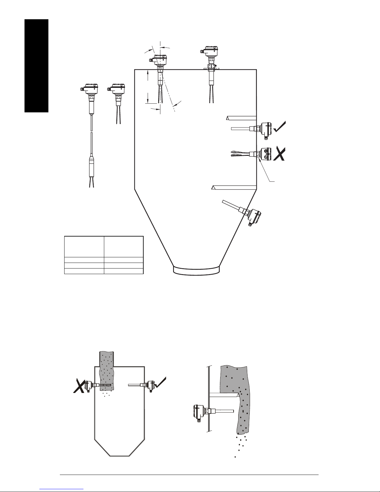
SITRANS LVS200 is normally mounted into the vessel top for full detection, or through the
tank wall at the detection level, for full, demand, or empty detection.
mmmmm
English
Cable
extension
version
Standard
version
*
L
α
Cable gland faces
downward to avoid
water penetration.
Sliding
bushing
version
Position tines vertically
to avoid product buildup: use a 50 mm openend wrench to turn the
process connection
until the tine
orientation marking
faces up or down.
Protection in case of
high material loading.
Tine orientation
marking facing
sideways.
*
max. deviation
from vertical
max. length L
α
5º 4 m
45º 1.2 m
>45º 0.6 m
Process Cautions
Caution:
• Locate SITRANS LVS200 out of path of falling material.
or:
• Protect shaft and tines from falling material.
Use angle mounting for flowing
material only.
If angle mounting is required
with high material loading,
customer-supplied protection
from falling material must be in
place.
Page EN-8 SITRANS LVS200 – INSTRUCTION MANUAL 7ML19985FT62
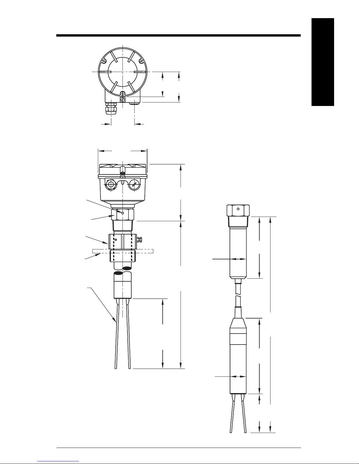
Dimensions
English
mmmmm
tine
orientation
marking
threaded
bushing
[max. temp.
80°C (176°F)]
optional
sliding
bushing*
customer
supplied
process
flange
tine
60 mm
(2.36")
120 mm
(4.72")
60 mm
(2.36")
Zone 21
(Cat. 2)
Zone 20
(Cat. 1)
165 mm (6.5"): compact solids/liquids interface model
230 mm (9.0"):compact standard version
300 to 40 00 mm (11.81 to 157"): customer-specified rigid
extension
75 mm
(2.95")
150 mm
(5.91")
Cable version
ø 42 mm
(1.67")
155 mm
(6.1")
*Note: The clamping screws of the sliding bushing
must be tightened to 10 Nm.
** Cable version with Liquids/solids interface
model option length to 7000 mm (275.59")
Cable version with NAMUR electronics length to
10 000 mm (393.7")
7ML19985FT62 SITRANS LVS200 – INSTRUCTION MANUAL Page EN-9
170 mm (6.69"):
standard fork
195 mm (7.68")
low density fork
700 to
20 000 mm**
(27.56 to 787")
195 mm
(7.68")
ø 42 mm
(1.67")
100 mm (3.94"):
solids/liquids
interface model

Wiring
mmmmm
English
WARNINGS:
• Open SITRANS LVS200 only when supply voltage is switched off.
• All field wiring must have insulation suitable for at least 250 V AC.
• A disconnect switch must be in close proximity to the equipment and
within easy reach of the operator.
• Use appropriate conduit or cable glands in hazardous locations.
Unused cable conduit fittings must be locked with a closing element or
plug.
• Observe all pertinent rules and regulations in the country of
installation.
Notes:
European requirements
• When mounting SITRANS LVS200 in hazardous areas, make sure the customer
supplied cable glands and/or plugs are certified ATEX 100a flameproof. The
certified temperature range must be at least -40 to 70 °C (-40 to 158 °F). The
minimum ingress protection requirement of IP6x according to European Standard
EN 60529 must be satisfied. Observe special conditions for safe use of the cable
gland described in the gland’s approval documentation.
• The requirements of European Standard EN 50281-1-2 regarding dust deposits and
temperature must be followed.
Connection recommendations
• Use a fuse for the signal output (max. 10 A).
• Provide protection for relay contacts to protect the device against spikes if inductive
loads are connected.
Precautions
• Before opening the lid, ensure there are no dust deposits around SITRANS LVS200,
and that the atmosphere around the instrument is settled.
• Make sure the main voltage does not exceed the maximum voltage listed on the
product label.
• Ensure that no more than 8 mm of each wire is stripped (to avoid danger of contact
with live parts).
• Ensure the boots for protecting cable terminations are no longer than 8 mm (to avoid
danger of contact with live parts).
Page EN-10 SITRANS LVS200 – INSTRUCTION MANUAL 7ML19985FT62
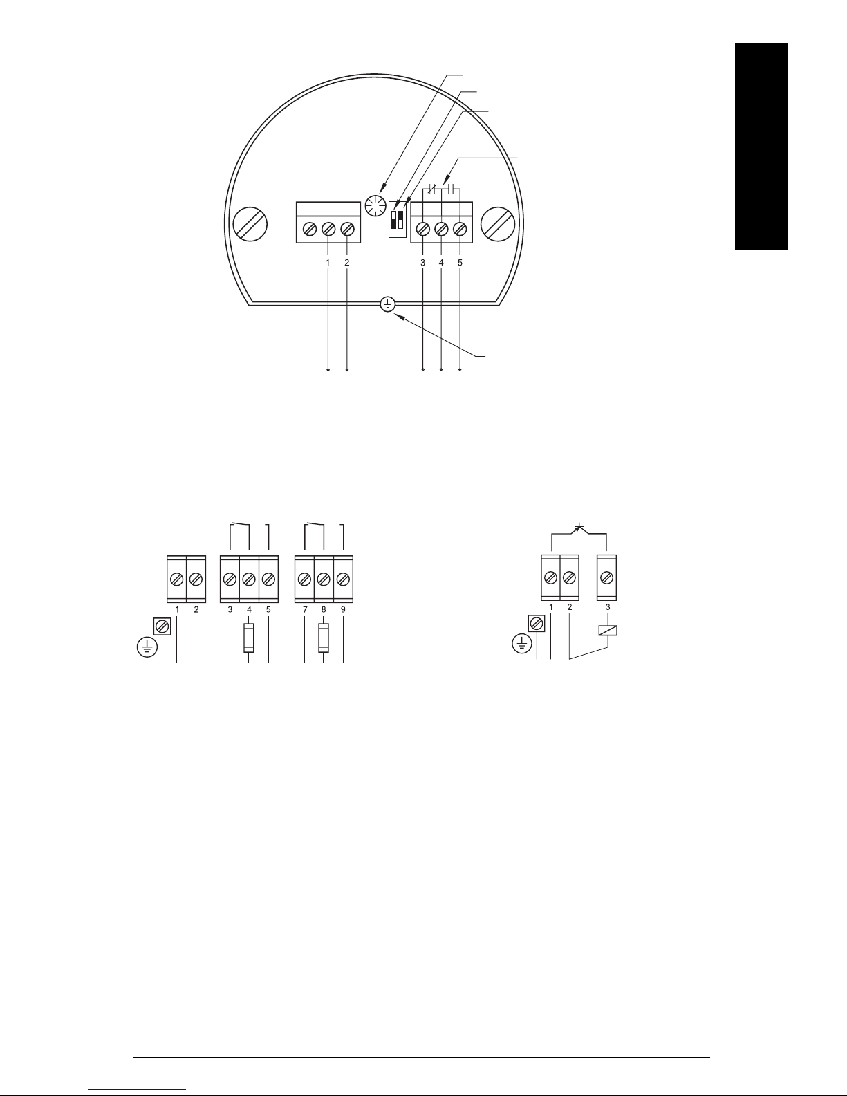
Universal voltage (SPDT relay)
AC: terminal 1: L
terminal 2: N
19 to 230 V AC, + 10 %, 50 to 60 Hz, 8 VA
DC: terminal 1: +
terminal 2: 19 to 55 V DC, + 10 %, 1.5 W
LED
FSH/FSL adjustment
sensitivity adjustment
B = factory setting,
A = decreased sensitivity
English
mmmmm
alarm output relay
FSL
B
A
FSH
protective earth terminal
Universal voltage (DPDT relay) 3-wire PNP
-
+
PE
N
L
signal output
-
+
AC: terminal 1: L
terminal 2: N
19 to 230 V AC, + 10 %, 50 to 60 Hz, 18 VA
DC: terminal 1: +
terminal 2: 19 to 55 V DC, + 10 %, 2 W
DC: terminal 1: +
terminal 2: 18 to 50 V DC, + 10 %, 1.5 W
PE
load
7ML19985FT62 SITRANS LVS200 – INSTRUCTION MANUAL Page EN-11
mmmmm
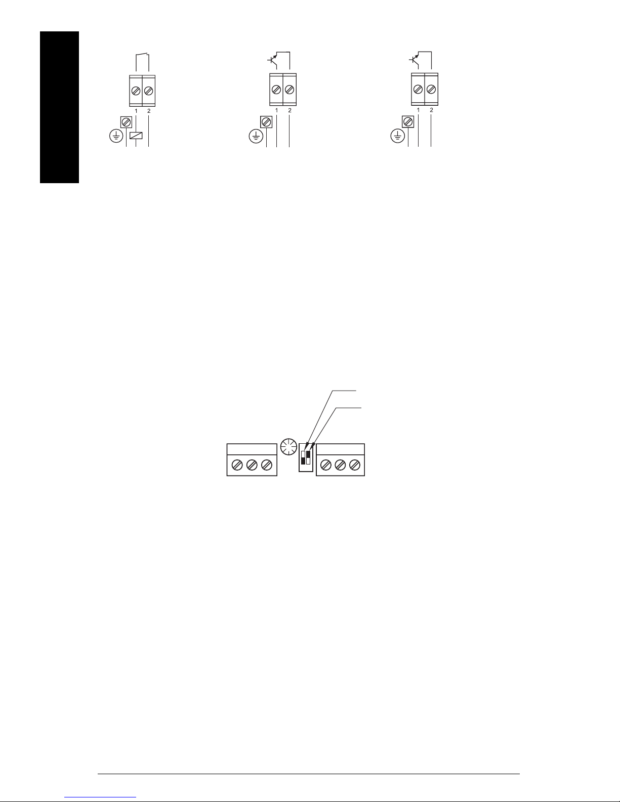
2-wire NAMUR IEC 60947-5-6 8/16 mA or 4 to 20 mA
English
-
+
PE
N
L
AC: terminal 1: L
terminal 2: N
19 to 230 V AC, + 10 %,
50 to 60 Hz, 1.5 VA
DC: terminal 1: +
terminal 2: 19 to 230 V DC, + 10 %, 1 W
-
+
PE
ca. 7 to 9 V DC,
intrinsically safe
(IEC 60947-5-6)
PE
DC: terminal 1: +
terminal 2: -
12.5 to 36 V DC, + 0 %
-
+
Sensitivity
If the measured material tends to cake or build up, the sensitivity adjustment switch can
be set to position A to decrease the sensitivity of the probe (factory setting is position B).
The sensitivity for interface applications should be set to position B, while the setting for
high-flow applications should be position A.
FSH/FSL adjustment or
High/Low Alarm setting (NAMUR)
sensitivity adjustment:
B = factory setting
FSL
B
A
FSH
A = decreased sensitivity
Page EN-12 SITRANS LVS200 – INSTRUCTION MANUAL 7ML19985FT62
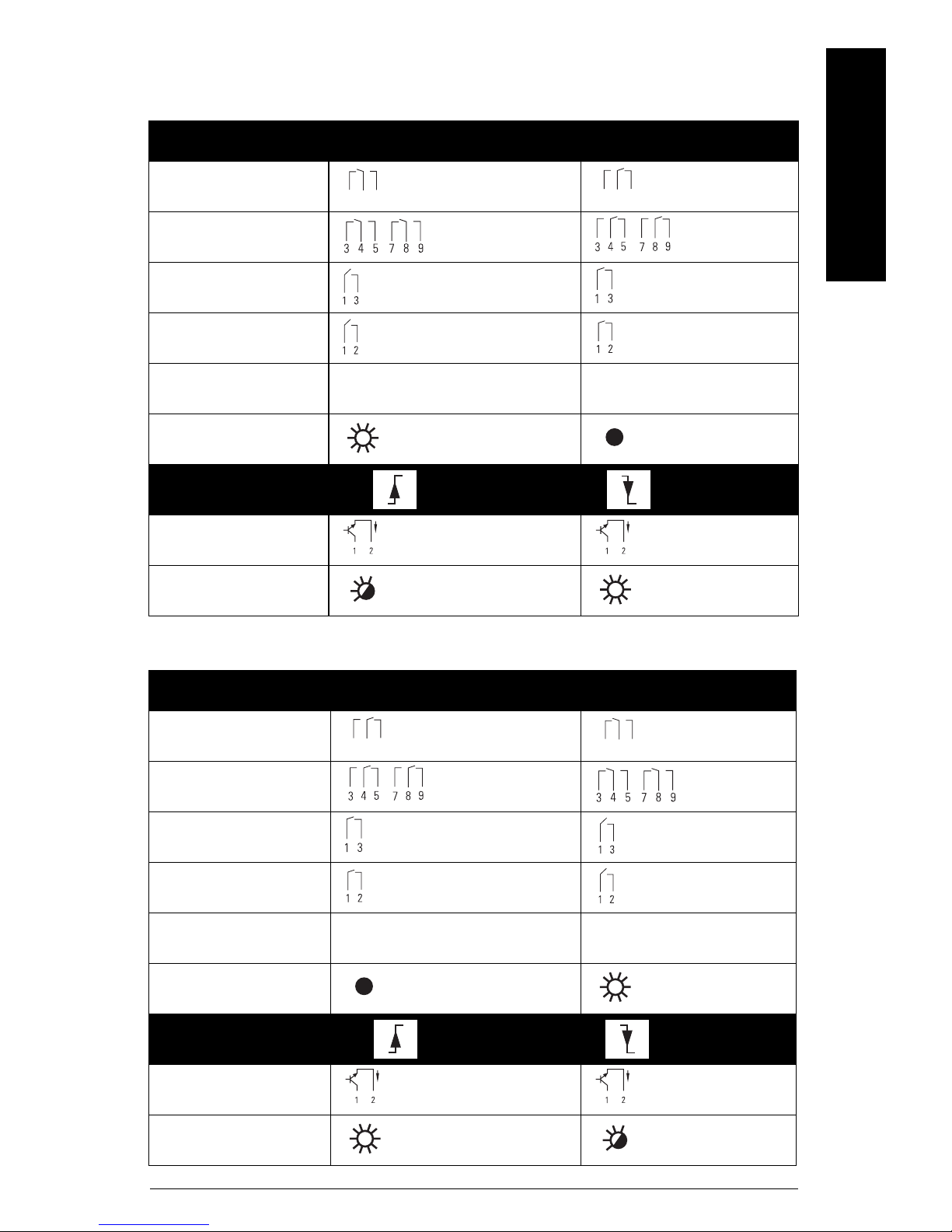
Switching Logic
Probe uncovered
Signal Output
Model Failsafe low Failsafe high
English
mmmmm
SPDT relay
4
5
3
5
4
3
DPDT relay
3-wire PNP
2-wire
8/16 mA I = 16 mA I = 8 mA
Signal Output LED
Low alarm setting High alarm setting
NAMUR IEC 60947-5-6 I < 1 mA I > 2.2 mA
Signal Output LED
Probe covered
Signal Output
Model Failsafe low Failsafe high
SPDT relay
5
4
3
DPDT relay
3-wire PNP
2-wire
8/16 mA I = 8 mA I = 16 mA
Signal Output LED
Low alarm setting High alarm setting
NAMUR IEC 60947-5-6 I >2.2 mA I < 1 mA
4
5
3
Signal Output LED
7ML19985FT62 SITRANS LVS200 – INSTRUCTION MANUAL Page EN-13
mmmmm
Signal output and test options
Note: The signal output and test options listed below apply only to specific power
supply options.
English
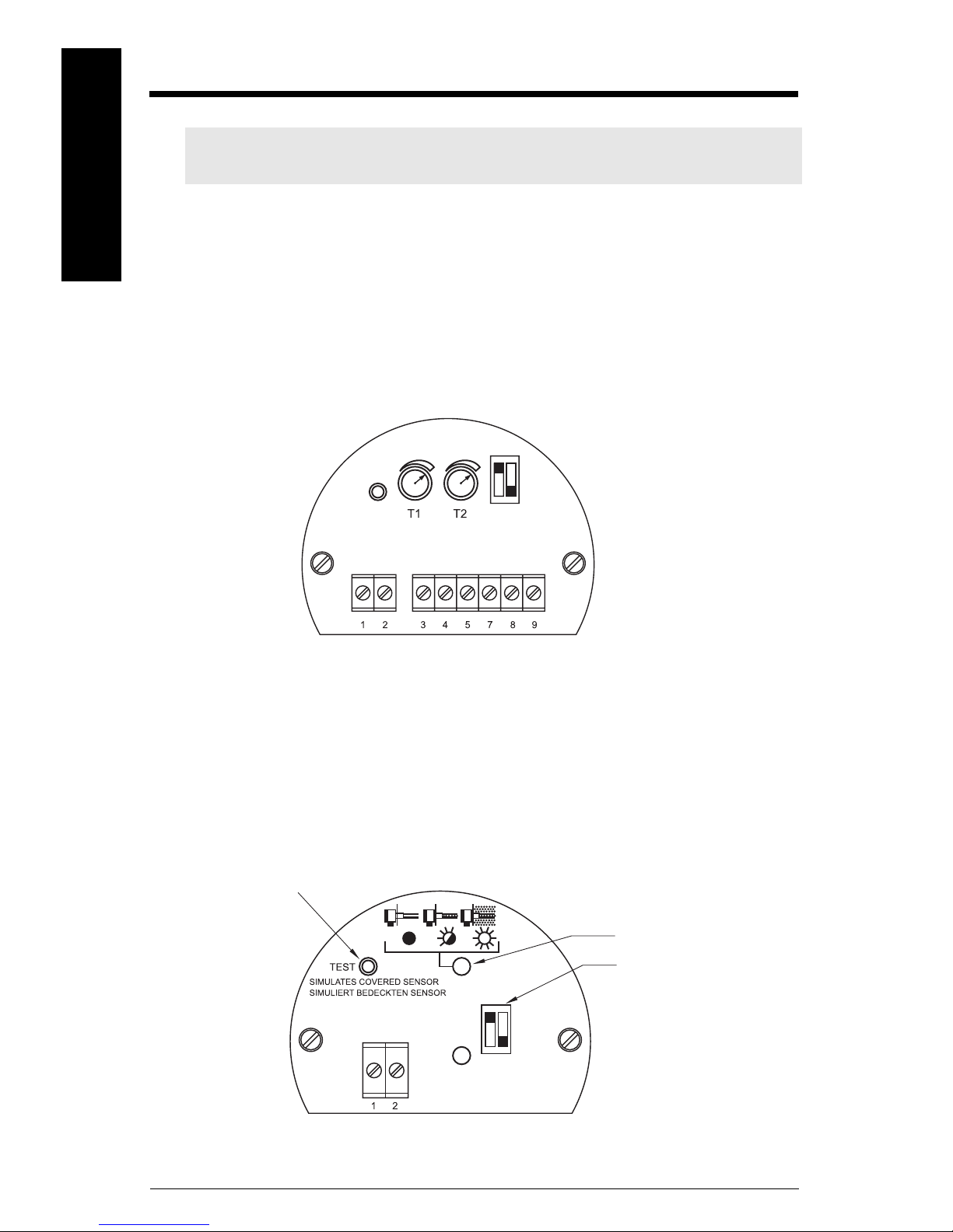
Signal Output Delay
Universal voltage (DPDT) model
The signal output can be delayed and is adjustable from 0 to 30 seconds. Turn the
potentiometer clockwise to increase the delay time.
Potentiometer T1: Delay when output switches from fork covered to uncovered.
Potentiometer T2: Delay when output switches from fork uncovered to covered.
Test function
NAMUR model (IEC 60947-5-6) and 8/16 mA or 4 to 20 mA model
If the fork is uncovered, pressing this button will stop the vibration and the signal output
will switch to indicate a covered fork. You can test the vibration and the electronics
without removing the LVS200 from the vessel. If the fork is covered, pressing the button
has no effect.
NAMUR model
Test button
Electronic module
diagnostic LED
sensitivity adjustment:
B = factory setting
B
A
A = decreased sensitivity
Page EN-14 SITRANS LVS200 – INSTRUCTION MANUAL 7ML19985FT62
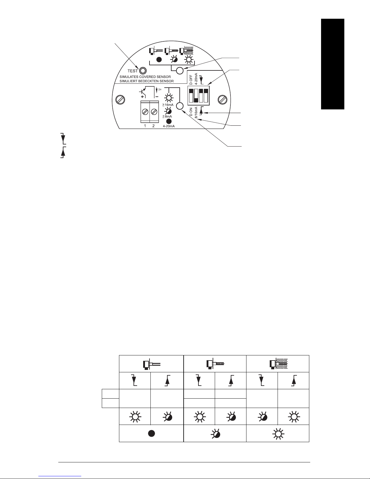
8/16 or 4 to 20 mA model
y
Test bu tton
diagnostic LED
sensitivity adjustment:
B = factory setting
B
A
Sensor switches at high level
Fail-safe function will default to full signal
Sensor switches at low level
Fail-safe function will default to empty signal
A = decreased sensitivit
filling or emptying
output setting
signal output LED
Vibration amplitude diagnosis
NAMUR module (IEC 60947-5-6) and and 8/16 mA or 4 to 20 mA model
Measurement quality is related to the vibration amplitude of the fork. The diagnostic LED
indicates the quality of the vibration being sent to the LVS200 electronics.
English
mmmmm
• Diagnostic LED off: measurement quality is good. The vibration amplitude is strong.
• Diagnostic LED blinking: measurement quality is poor and vibration amplitude is
decreasing as fork becomes encrusted. When this happens, set the sensitivity
switch to decreased sensitivity.
• Diagnostic LED on: vibration has stopped and fork is fully encrusted with material.
Current output setting
8/16 mA
The chart below illustrates the output current when:
•Fork is clean
• Fork is encrusted: weak vibration amplitude is shown
• Fork is fully encrusted and vibration has stopped.
Diagnosis
Setting
Signal
output LED
Diagnosis
LED
D Off
D On I = 20 mA I = 6 mA
I = 16 mA I = 8 mA
I = 16 mA I = 8 mA
I = 8 mA I = 16 mA
7ML19985FT62 SITRANS LVS200 – INSTRUCTION MANUAL Page EN-15
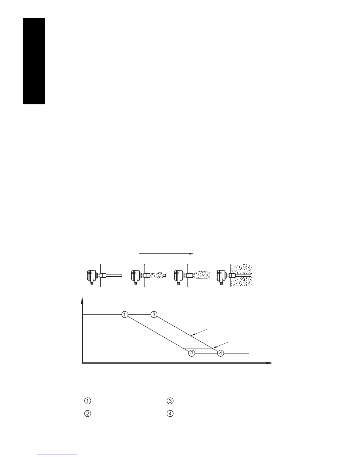
mmmmm
The output current can indicate weak vibration amplitude with the diagnosis setting D
ON. If the diagnosis is set to D OFF, the output will be either 8 mA or 16 mA depending on
high or low level settings.
If the diagnosis is set to D ON, the output will change from 16 to 20 mA and from 8 to 6 mA
if the vibration is weak. This output can be passed to an external 4 to 20 mA output. There
English
is an internal delay of 10 seconds before the change happens, so that the external output
does not indicate a weak vibration when the vibration is stopped and started during
normal measurement operation.
Buildup Detection (8/16 mA or 4 to 20 mA version)
With the 4 to 20 mA setting, you can recognize material buildup on the fork using a PLC or
data logger.
In this mode, the Diagnostic setting has no influence. The LED showing signal output is
off.
20 mA: The fork is clean.
<20 mA and >12/12.5 mA: The vibration amplitude is decreased by the material buildup.
<12/12.5 mA and >7/8 mA: This range indicates a weak vibration. The internal LED
showing diagnosis begins blinking to indicate a weak signal. If you are using a PLC to
evaluate the echo, delay the response time to this indicator for approximately 10 seconds.
A hysteresis of 0.5 mA (between 12 and 12.5 mA) is recommended.
7/8 mA: This point indicates that the fork is mostly encrusted.
6 mA: This point indicates that the fork is fully encrusted.
increasing material buildup
20 mA
s
t
a
output current
With standard sensitivity setting
d
e
c
r
e
a
s
e
d
s
e
n
n
d
a
r
d
s
e
n
s
i
t
i
v
i
Vibration damping by material
s
i
t
i
v
i
t
y
t
y
With decreased sensitivity setting
12/12.5 mA
7/8 mA
6 mA
Amplitude is 100%
Amplitude is 0%
Page EN-16 SITRANS LVS200 – INSTRUCTION MANUAL 7ML19985FT62
Amplitude is 100%
Amplitude is 0%

Maintenance
SITRANS LVS200 requires no maintenance or cleaning under normal operating
conditions. Under severe operating conditions, the tines may require periodic cleaning.
Brush off any accumulated deposits, taking care not to bend the tines.
Unit Repair and Excluded Liability
All changes and repairs must be done by qualified personnel, and applicable safety
regulations must be followed. Please note the following:
• The user is responsible for all changes and repairs made to the device.
• All new components must be provided by Siemens Milltronics Process Instruments Inc.
• Restrict repair to faulty components only.
• Do not re-use faulty components.
English
mmmmm
7ML19985FT62 SITRANS LVS200 – INSTRUCTION MANUAL Page EN-17
SITRANS LVS200 Pipe Extended Version
)
mmmmm
Assembly
English
Suggested tools:
• medium Phillips or 6 to 8 mm (¼”) flat screwdriver • terminal crimper
• 3 mm (1/8”) flat screwdriver • 36 mm open end wrench
• wire cutters • pipe wrench
•wire strippers
enclosure
customer supplied
pipe extension
fork assembly
1. Open the enclosure lid; remove electronics module.
2. Lead the sensor cable through the customer supplied 1" tube and enclosure.
3. Assemble the fork assembly, the pipe extension, and the enclosure using the 36 mm
open end wrench. Seal the pipe threads with an appropriate sealant.
Note: Do not turn fork assembly. Do not bend the fork during assembly.
4. Line up the fork and the tine orientation marking as shown in dimension drawing on
page 9. (The tine orientation marking on the process connection is to identify the
vertical orientation of the fork.)
220 mm
(8.7")
150 mm (5.9")
8 mm max.
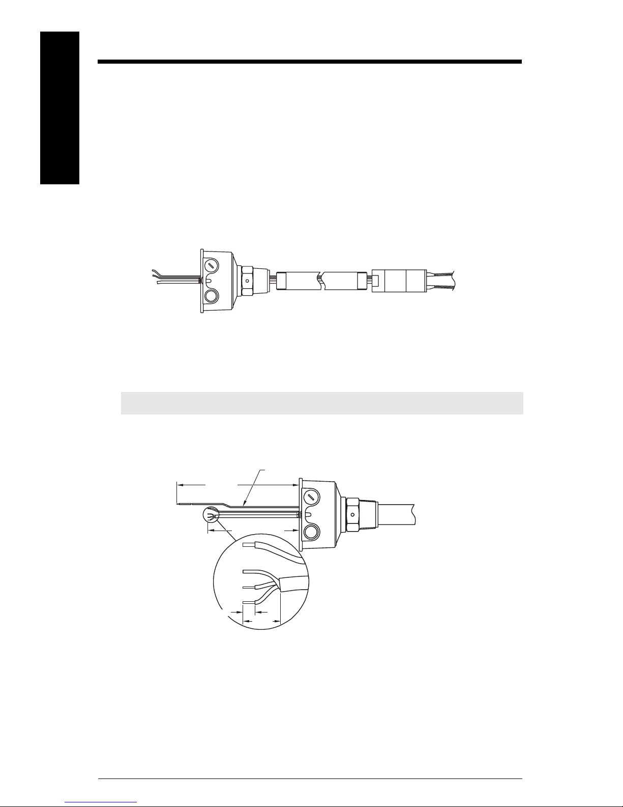
5. Shorten sensor cable to a free length of 150 mm (5.9").
earth cable (green/yellow
18 mm
6. Shorten earth cable to a free length of 220 mm (8.7").
7. Prepare sensor cable as shown above, stripping a maximum of 8 mm from each
wire.
Page EN-18 SITRANS LVS200 – INSTRUCTION MANUAL 7ML19985FT62
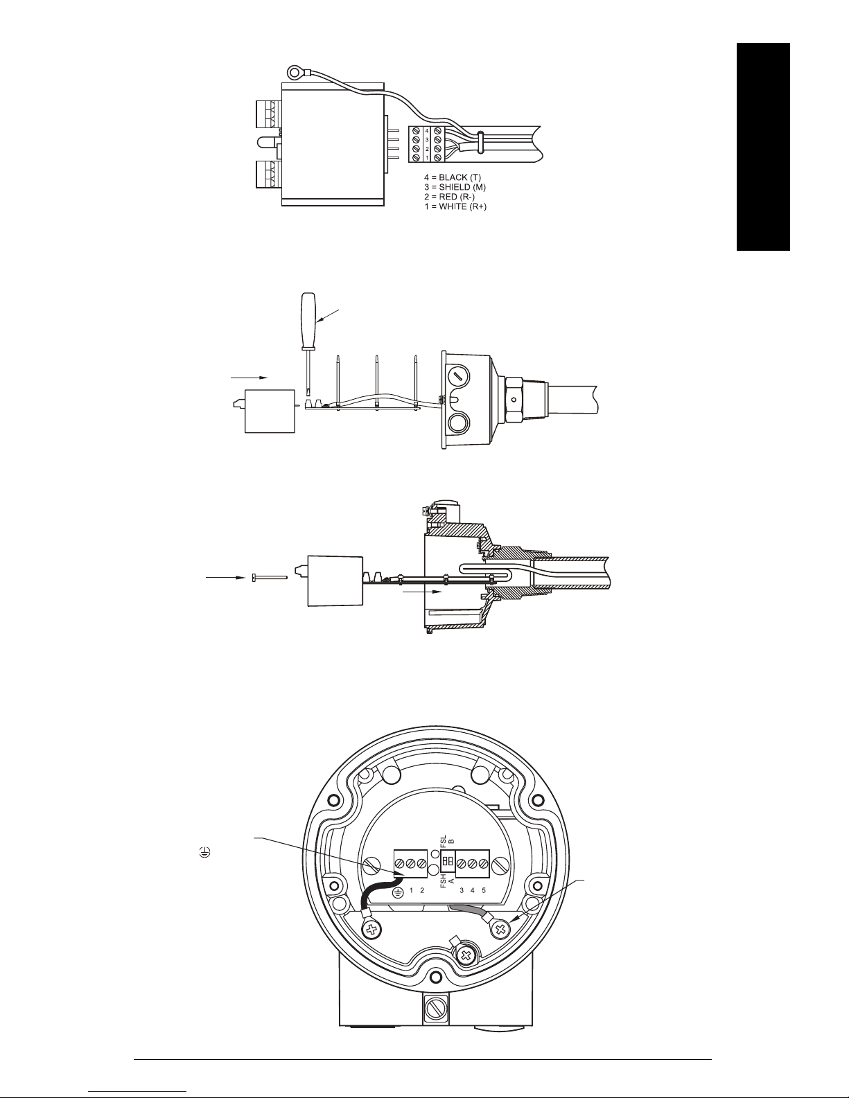
electronics
module, flat
side up
8. Connect the sensor cable to the terminal connection board shown above.
9. Secure the sensor cable with cable ties.
10. Crimp the ring terminal 4 mm (0.19") to sensor earth cable.
3 mm (1/8”) screw driver
cable ties
11. Connect electronics module and terminal connection board. Be sure that all
terminals are tight.
English
mmmmm
12. Insert the electronics module into the housing. The terminal connection board is
used to guide the cable into the extension tube.
13. Fold cable as shown in diagram above.
14. Secure the electronics module as shown in diagram below.
Connect protection earth
of the enclosure to
terminal of the
electronics module.
Connect earth cable
of the fork to the
electronics earth
terminal.
7ML19985FT62 SITRANS LVS200 – INSTRUCTION MANUAL Page EN-19
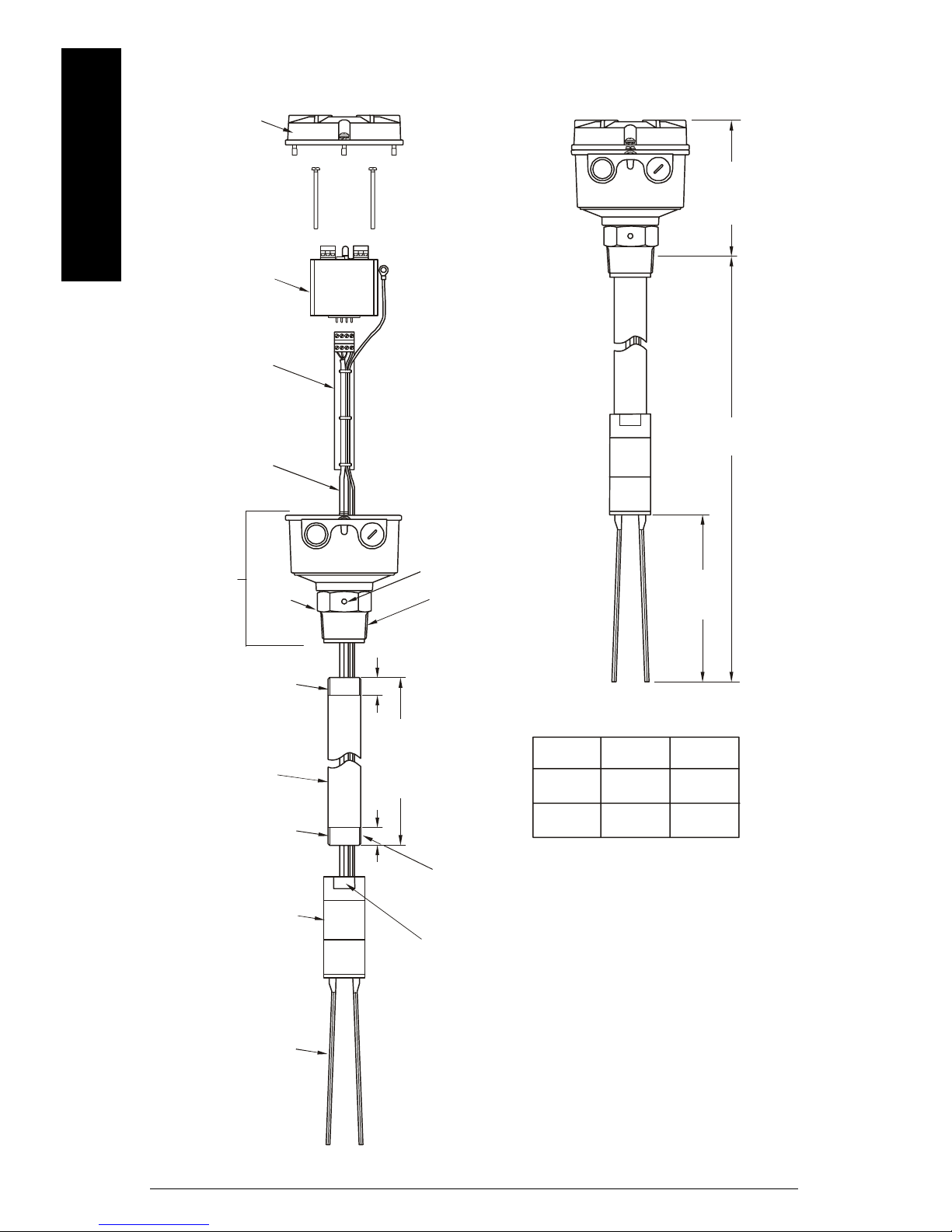
Assembly Overview Drawing
lid
mmmmm
English
electronics module
terminal connection
board
sensor cable
enclosure
assembly
process
connection
thread G1” or 1" NPT
(use appropriate
thread sealant)
tine orientation marking
process thread 1 ½” NPT or
1 ½” BSP
min.
18 mm
(0.75")
approx.
138 mm
(5.4")
L = 300 to 3800 mm
(11.8 to 149.6")
170 mm
(6.7")
1" schedule 40 pipe
(internal min.
dia. 25.4 mm (customer
supplied and mounted)
thread G1” or 1" NPT
(use appropriate
thread sealant)
fork assembly
fork
X = L - 255 mm
(10")
min.
18 mm
(0.75")
SW 36
Note: Threaded
engagement to be a
min. of 7 mm (0.27")
process
thread
1 1/2" NPT
1 1/2" BSP
cable
entries
1/2" NPT
M20x1.5
1" pipe
thread
1" NPT
G 1"
Page EN-20 SITRANS LVS200 – INSTRUCTION MANUAL 7ML19985FT62
Sicherheitshinweise
Warn- und Hinweistexte müssen besonders beachtet werden. Diese sind grau hinterlegt
vom übrigen Text abgesetzt.
WARNUNG: bezieht sich auf ein Warnsymbol auf dem Produkt und
bedeutet, dass bei Nicht-Einhalt der entsprechenden Vorsichtsmaßnahmen Tod, schwere Körperverletzung und/oder erheblicher Sachschaden eintreten können.
WARNUNG
1
: bedeutet, dass bei Nicht-Einhalt der entsprechenden
Vorsichtsmaßnahmen Tod, schwere Körperverletzung und/oder
erheblicher Sachschaden eintreten können.
VORSICHT: bedeutet, dass bei Nicht-Einhalt der entsprechenden Vorsichtsmaßnahmen erheblicher Sachschaden eintreten kann.
Hinweis:
Betriebsanleitung, auf den besonders aufmerksam gemacht werden soll.
1.
Dieses Symbol wird verwendet, wenn sich kein entsprechendes
Vorsichtssymbol auf dem Produkt befindet.
steht für eine wichtige Information über das Produkt selbst oder den Teil der
Sicherheitssymbole
In der Betriebsanleitung
Auf dem
Produkt
Beschreibung
(Etikett auf dem Produkt: gelber Hintergrund.)
Vorsicht: Details sind in zugehörigen Dokumenten
(Betriebsanleitung) aufgeführt.
Deutsch
mmmmm
Erde (Masseklemme)
Schutzleiterklemme
Die Betriebsanleitung
Hinweise:
• Bitte beachten Sie die Vorschriften für Installation und Betrieb, um eine schnelle,
problemlose Installation, sowie maximale Genauigkeit und Zuverlässigkeit Ihres
SITRANS LVS200 zu gewährleisten.
• Diese Betriebsanleitung bezieht sich ausschließlich auf den SITRANS LVS200.
Mit Hilfe der vorliegenden Anleitung können Sie Ihren SITRANS LVS200 optimal einstellen. Für Vorschläge und Bemerkungen zu Inhalt, Aufbau und Verfügbarkeit der
Betriebsanleitung sind wir jederzeit offen.
Bitte richten Sie Ihre Kommentare an techpubs.smpi@siemens.com
www.siemens.com/processautomation finden Sie ein vollständiges Archiv aller Siemens
Milltronics Betriebsanleitungen.
. Unter
7ML19985FT62 SITRANS LVS200 – BETRIEBSANLEITUNG Seite DE-1

SITRANS LVS200: Einleitung
Hinweise:
• Installation, Wartung und Inbetriebnahme müssen durch qualifiziertes, technisches
Personal vorgenommen werden.
• Der SITRANS LVS200 darf nur gemäß den Anweisungen in dieser Betriebsanleitung verwendet werden.
Drei Ausführungen des SITRANS LVS200 stehen zur Verfügung:
• Der SITRANS LVS200, Standardausführung, ist ein Vibrations-Grenzstandschalter,
der die An- oder Abwesenheit rieselfähiger Schüttgüter in Behältern, Silos oder
Trichtern erfasst. SITRANS LVS200 liefert einen Signalausgang zur Anzeige eines
Min. oder Max. Alarms. Unterschiedliche Produkte können gemessen werden, wie
mmmmm
Deutsch
z. B. Kalk, Styropor, Mehl und Kunststoffgranulat. SITRANS LVS200 hat ein kompaktes Design und kann senkrecht oder waagrecht eingebaut werden. Die StandardSchwinggabelsonde des LVS200 ist auch mit verschiedenen Seilverlängerungen bis
maximal 20 000 mm (787") verfügbar. Für erhöhte Empfindlichkeit steht optional eine
längere Schwinggabelsonde zur Verfügung. Die Seilverlängerung des SITRANS
LVS200 ist nur für den Einbau von oben geeignet. Die vibrierende Schwinggabel
bewirkt eine gewisse Selbstreinigung des Gerätes vom Messstoff.
• Die Ausführung Trennschichtmessung Flüssigkeiten/Schüttgüter des SITRANS
LVS200 ist ein Vibrations-Grenzstandschalter, der auch abgesetzte Feststoffe in
Flüssigkeiten oder Feststoffe in beengten Anlagen, wie z. B. Speiserohren, erfassen
kann. Diese Ausführung ist so konzipiert, dass Flüssigkeiten ignoriert werden, um
die Trennschicht zwischen einem Feststoff und einer Flüssigkeit zu erfassen. Die mit
diesem Design verbundene kurze Schwinggabelsonde ist auch mit verschiedenen
Seilverlängerungen bis maximal 20 000 mm (787"), nur für den Einbau von oben verfügbar.
• Die Ausführung Rohrverlängerung des SITRANS LVS200 ist ein Vibrations-Grenzstandschalter, bei dem ein kundenseitiges Verlängerungsrohr [max. Länge 3800 mm
(150")] mit der Standard- oder Flüssigkeit/Feststoff-Ausführung (kurz) von LVS200
Schwinggabel und Elektronik verbunden wird. Dadurch kann die Elektronik für Sonderapplikationen von der Schwinggabel abgesetzt werden. Angaben zum Aufbau
finden Sie unter
SITRANS LVS200 Ausführung mit Rohrverlängerung
auf Seite 18.
Wesentliche Merkmale
• Hohe mechanische Beständigkeit
• Starke Schwingung, auch für hohe Belastungen geeignet
• Verdrehbares Gehäuse
• 1½” NPT oder 1½” BSPT Edelstahl-Gewindeanschluss, oder BSP oder NPT Schiebemuffe. DN 100 und 2, 3, 4" ASME Flanschoptionen verfügbar.
• Für leichtes Material geeignet
Standardausführung: 20 g/l (1,2 lb/ft
Standardausführung mit
Schwinggabel niedriges Schüttgewicht: 5 g/l (0,3 lb/ft
Ausführung Trennschichtmessung: 50 g/l (3 lb/ft
Seite DE-2 SITRANS LVS200 – BETRIEBSANLEITUNG 7ML19985FT62
3
)
3
)
3
)

Anwendungsbereiche
• Trockenkalk, Styropor, Mehl, Kunststoffgranulat
• Trockenes Schüttgut mit hoher oder geringer Dichte
• Trennschichterfassung von Feststoffen in einer Flüssigkeit (Filterbett)
• Flüssigkeit/Feststoff-Ausführung des LVS200 unterscheidet die Zustände Durchfluss/kein Durchfluss in Rohren
Arbeitsprinzip
Ein Signal vom elektrischen Schaltkreis bewirkt eine piezoelektrische Anregung der
Sonde, die zum Schwingen gebracht wird. Wird die Sonde durch das Füllgut bedeckt, so
wird die dadurch entstehende Dämpfung elektronisch registriert und ein entsprechender
Schaltausgang nach einer Sekunde Ansprechverzögerung betätigt. Sobald die Schwingsonde frei vom Materialdruck ist, nimmt die Schwingung wieder auf und das Relais kehrt
in seinen normalen Zustand zurück.
WARNUNGEN:
• Dieses Produkt wird als druckhaltendes Ausrüstungsteil im Sinne der
Richtlinie 97 / 23 / EG bezeichnet und ist nicht
heitsvorrichtung bestimmt.
für den Einsatz als Sicher-
Deutsch
mmmmm
• Die Werkstoffe werden entsprechend ihrer chemischen Beständigkeit
(oder Trägheit) für allgemeine Zwecke gewählt. Bei Einsatz in besonderen Umgebungen prüfen Sie vor Installation die chemische Beständigkeit anhand einschlägiger Tabellen.
7ML19985FT62 SITRANS LVS200 – BETRIEBSANLEITUNG Seite DE-3

Technische Daten
Hinweis: Siemens Milltronics ist bestrebt, die Genauigkeit der technischen Daten zu
gewährleisten, behält sich jedoch jederzeit das Recht auf Änderung vor.
Versorgungsspannung
• AC 19 ... 230 V, +10 %, 50 ... 60 Hz, 8 VA
• DC 19 ... 55 V, +10 %, 1,5 W
• DC 18 ... 50 V 3-Leiter PNP
• DC 7 ... 9 V (NAMUR Trennverstärker erforderlich) NAMUR IEC 60947-506, 2-Leiter
• 8/16 mA oder 4 ... 20 mA; DC 12,5 ... 35 V, 2-Leiter
mmmmm
Funktion
Deutsch
Messfrequenz
• Standard ca. 125 Hz
• Ausführung Trennschichtmessung ca. 350 Hz
• Option erhöhte Empfindlichkeit ca. 90 Hz
Signalverzögerung
• Sonde frei / bedeckt ca. 1 Sekunde
• Sonde bedeckt / frei ca. 1 bis 2 Sekunden
Relais Ansprechverzögerung (DPDT Ausführung)
• Einstellbar bis 30 Sekunden
Empfindlichkeit
• Max. oder Min., über Schalter wählbar
Min. Schüttgewicht
• Standardausführung ca. 20 g/l (1,2 lb/ft³)
• Standardausführung mit Schwinggabel
niedriges Schüttgewicht 5 g/l (0,3 lb/ft³)
• Ausführung Trennschichtmessung ca. 50 g/l (3 lb/ft³)
Maximale Korngröße
• 10 mm (0.39")
Alarmausgang
• Ausführung mit 1 Relais SPDT Relais
• Ausführung mit 2 Relais DPDT Relais
• Relais Failsafe Max oder Min, über Schalter wählbar
• Relais 8 A bei AC 250 V, ohmsche Last; Relais 5 A bei DC 30 V, ohmsche Last
• 3-Leiter PNP Open Collector: Dauerlast
Seite DE-4 SITRANS LVS200 – BETRIEBSANLEITUNG 7ML19985FT62
maximal 0,4 A, kurzschluss- und
überlastfest;
Schaltspannung: max. 50 V (Verpolungsschutz)
 Loading...