

Siemens SITRANS LVS100, SITRANS LVS200 Operating Instructions Manual
Vibrating Switches
SITRANS LVS100/200
Operating Instructions 08/2012
SITRANS

Safety Notes
Special attention must be paid to warnings and notes highlighted from the rest of the text
by grey boxes.
WARNING: relates to a caution symbol on the product, and means
that failure to observe the necessary precautions can result in
death, serious injury, and/or considerable material damage.
WARNING
precautions can result in death, serious injury, and/or considerable
material damage.
CAUTION: means that failure to observe the necessary precautions can
result in considerable material damage.
Note:
manual.
1.
means important information about the product or that part of the operating
This symbol is used when there is no corresponding caution symbol on the
product.
Safety marking symbols
1
: means that failure to observe the necessary
English
mmmmm
In
Manual
On
Product
Description
(Label on product: yellow background.)
Caution: refer to accompanying documents (manual) for details.
(Caution symbol on product) Warning: Risk of electric shock
Earth (ground) Terminal
Protective Conductor Terminal
7ML19985FT63 SITRANS LVS100/200 – INSTRUCTION MANUAL Page EN-1

mmmmm
The Manual
Notes:
• Please follow the installation and operating procedures for a quick, trouble-free
English
• This manual applies to SITRANS LVS100 and SITRANS LVS200 only.
• Product details and instructions in this manual relate to both SITRANS LVS100 and
• This product is intended for use in industrial areas. Operation of this equipment in a
This manual will help you set up your SITRANS LVS100/200 for optimum performance. We
always welcome suggestions and comments about manual content, design, and
accessibility.
Please direct your comments to techpubs.smpi@siemens.com
Siemens Milltronics manuals, go to www.siemens.com/processautomation.
installation and to ensure the maximum accuracy and reliability of your
SITRANS LVS100/200
SITRANS LVS200 unless otherwise stated.
residential area may cause interference to several frequency based
communications.
. For the complete library of
Page EN-2 SITRANS LVS100/200 – INSTRUCTION MANUAL 7ML19985FT63

SITRANS LVS100 and LVS200
Introduction
Notes
• Installation, maintenance, and commissioning must be performed by qualified
technical personnel.
• SITRANS LVS100/200 must be used only in the manner outlined in this instruction
manual.
The SITRANS LVS100 and SITRANS LVS200 are available in a standard version, with the
SITRANS LVS200 offering two additional versions.
SITRANS LVS100, SITRANS LVS200 - Standard Version
• SITRANS LVS100/200 standard version is a vibrating level switch that detects high
or low levels of dry bulk solids in bins, silos, or hoppers. It has a compact design that
allows it to be top or side mounted and the vibrating fork ensures that the tines are
kept clean.
• SITRANS LVS100 is an entry level solids fork with a bulk density limit starting
at 60 g/l (3.8 lb/ft
4 000 mm (157").
• SITRANS LVS200 provides several output options for indication of point level
with products such as lime, styrofoam, flour, and plastic granules, starting at
20 g/l (1.2 lb/ft
measure bulk densities of less than 5g/l. In addition, the LVS200 has a wider
range of process configurations. SITRANS LVS200 standard length fork is
available with variable cable extension lengths to a maximum of 20 000 mm
(787") (cable extensions for top mount applications only). An optional longer
fork is available for increased sensitivity.
3
). The LVS100 is available with rigid extension options to
3
). It handles a broader range of applications and is able to
English
mmmmm
SITRANS LVS200 - Liquid/Solid Interface Version
• The SITRANS LVS200, liquid/solid interface version, is a vibrating level switch that
can also detect settled solids within liquids, or solids within confined spaces such
as feed pipes. This version is designed to ignore liquids in order to detect the
interface between a solid and a liquid. The design incorporates a short fork, and is
also available with variable cable extension lengths to a maximum of 7 000 mm
(275.59"), for top mount applications only.
SITRANS LVS200 - Pipe Extension Version
• The SITRANS LVS200, pipe extension version, is a vibrating level switch that
incorporates a customer supplied pipe extension [maximum length 3800 mm (150")]
with the standard or liquid/solid (short) LVS200 fork and electronics. This allows for
separation of the electronics and tuning fork for applications requiring a rigid
extension. Please see
information on assembly.
7ML19985FT63 SITRANS LVS100/200 – INSTRUCTION MANUAL Page EN-3
SITRANS LVS200 Pipe Extended Version on page 26
for

mmmmm
Product Features
• High resistance to mechanical forces
• Strong vibration resistance to high bulk material loads
• Rotatable enclosure
• LVS100: R 1½" (BSPT); 1¼" NPT (Taper) threaded connection
English
• LVS200: Stainless steel 1½” NPT or R 1½” (BSPT) threaded connection, or R 2"
(BSPT) or NPT sliding sleeve. DN 100 and 2, 3, 4" ASME flange and Triclamp 2"
options available.
• Suitable for high or low density material
LVS100 standard version: 30 g/l (1.9 lb/ft
LVS200 standard version: 20 g/l (1.2 lb/ft
LVS200 standard version with low density fork: 5 g/l (0.3 lb/ft3) min.
LVS200 liquid/solid interface version: 50 g/l (3.0 lb/ft
Product Applications
• Dry lime, styrofoam, flour, plastic granules
• High or low density, dry bulk materials
• Interface detection of a solid within a liquid (filter beds)
• Flow or no flow detection in pipe using liquid/solid LVS200 version
3
) min.
3
) min.
3
) min.
Principle of Operation
A signal from the electronic circuit excites a crystal in the probe, causing the fork to
vibrate. If the fork is covered by material, the change in vibration is detected by electronic
circuitry which causes the relay to change state after a one second delay. When the
material no longer reaches the tines, full vibration resumes and the relay reverts to its
normal state.
WARNINGS:
• This product is designed as a Pressure Accessory per Directive 97 / 23 / EC
and is not
• Materials of construction are chosen based on their chemical
compatibility (or inertness) for general purposes. For exposure to
specific environments, check with chemical compatibility charts
before installing.
intended for use as a safety device.
Page EN-4 SITRANS LVS100/200 – INSTRUCTION MANUAL 7ML19985FT63

Specifications
Note: Siemens Milltronics makes every attempt to ensure the accuracy of these
specifications but reserves the right to change them at any time.
Power
LVS10 0
• 19 to 230 V AC,
LVS20 0
• 19 to 230 V AC, +10 %, 50 to 60 Hz, 1.8 VA / 19 to 55 V DC, +10 %, 1.5 W
• 18 to 50 V DC 3-wire PNP
• 7 to 9 V DC (requires NAMUR switch amplifier) NAMUR IEC 60947-506, 2-wire
• 8/16 mA or 4 to 20 mA; 12.5 to 35 V DC, 2-wire
10 %, 50 to 60 Hz, 22 VA / 19 to 40 V DC, 10 %, 2 W
Performance
Measuring frequency
LVS10 0
• standard approx. 200 Hz
LVS20 0
English
mmmmm
• standard approx. 125 Hz
• liquid/solid interface version approx. 350 Hz
• enhanced sensitivity option approx. 90 Hz
Signal delay
• probe uncovered to covered approx. 1 second
• probe covered to uncovered approx. 1 to 2 seconds
Relay delay (DPDT version) (LVS200)
• adjustable up to 30 seconds
Sensitivity
• high or low, switch selectable
Minimum material density
LVS10 0
• standard version approx. 30 g/l (1.9 lb/ft
LVS20 0
• standard version approx. 20 g/l (1.2 lb/ft³)
• standard version with low density fork approx. 5 g/l (0.3 lb/ft³)
• liquid/solid interface version approx. 50 g/l (3 lb/ft³)
3
)
7ML19985FT63 SITRANS LVS100/200 – INSTRUCTION MANUAL Page EN-5

mmmmm
Alarm Output
English
Maximum particle size
• LVS100 8 mm (0.32")
• LVS200 10 mm (0.39")
LVS10 0
• version with 2 relays DPDT relay
relay fail-safe: high or low,
switch selectable
relay 8 A at 250 V AC,
non-inductive / relay 5 A at 30 V DC,
non-inductive
LVS20 0
• version with 1 relay SPDT relay
relay fail-safe: high or low,
switch selectable
relay 8 A at 250 V AC,
non-inductive / relay 5 A at 30 V DC,
non-inductive
• version with 2 relays DPDT relay
relay fail-safe: high or low,
switch selectable
relay 8 A at 250 V AC,
non-inductive / relay 5 A at 30 V DC,
non-inductive
• 3-wire PNP open collector: permanent load
maximum 0.4 A, short circuit and
overload protected;
turn-on voltage: max. 50 V (reverse
protection)
• mA output (build-up detection) 8/16 mA or 4 to 20 mA;
resolution 4 to 20 mA, ±0.1 mA
Page EN-6 SITRANS LVS100/200 – INSTRUCTION MANUAL 7ML19985FT63

Mechanical
Process Connection
LVS10 0
• thread R 1½" (BSPT); 1¼" NPT (Taper)
ANSI B 1.20.1
• thread material stainless steel 316 Ti (1.4581) or
304 (1.4301) for specific configurations
LVS20 0
• thread 1½” NPT (Taper), R 1½” (BSPT)
• thread material stainless steel 304 (1.4301) or
optional stainless steel 316 Ti (1.4571)/
316L (1.4404)
• flanges DN 100 PN6, DN 100 PN16,
2", 3", 4" ASME 150 lb flanges
• optional sliding bushing with R 2" (BSPT) or NPT (Taper) thread
• Tri-clamp 2" (DN50) ISO 2852
Tines
• tine material stainless steel 316Ti (1.4571)/ 316L (1.4581)
1
(PTFE
coated tines are available upon special request. Contact your local Siemens
representative for ordering information.)
English
mmmmm
Enclosure
• construction epoxy-coated aluminum
• conduit entry 2 x M20x1.5, or 2 x ½” NPT
• ingress protection Type 4X/NEMA 4X/IP66
Weight
• standard version, no extensions 2.0 kg (4.4 lb)
• solids/liquids, no extensions 1.9 kg (4.2 lb)
Environmental
• location indoor/outdoor
• altitude max. 2000 m (6562 ft)
• ambient temperature –40 to +60 °C (–40 to +140 °F)
• relative humidity 0 to 100% (suitable for outdoor: ingress
• overvoltage category II
• pollution degree 2
protection: Type 4X/NEMA 4X/IP66)
1.
Polytetrafluoroethylene
7ML19985FT63 SITRANS LVS100/200 – INSTRUCTION MANUAL Page EN-7

mmmmm
Process
English
Temperature
• All approvals except CSA Class II,
Group G: –40 to +150 °C (–40 to +302 °F)
• CSA Class II, Group G: –40 to +140 °C (–40 to +284 °F), CSA
temperature code T3B
• For applications with process temperature greater than +80 °C (+176 °F), the
maximum threaded bushing surface temperature must not exceed +80 °C (+176 °F)
• Maximum enclosure surface temperature (Category 2D): +120 °C (+248 °F) (ATEX
relevant)
• Maximum extension surface temperature (Category 1D): +150 °C (+302 °F) (ATEX
relevant)
Note: SITRANS LVS200 can be installed with an optional temperature isolator
extension. The isolator increases the distance of the electronics from the process
surface, thus allowing for a higher ambient temperature. See “Temperature Isolator
Option (LVS100/200)” on page 11. for more information.
Pressure
• max 10 bar, gauge (145 psi, gauge)
Note: Pressure information for hazardous areas
The device construction allows over-pressure up to 10 bar. This pressure is allowed for
test purposes. The ATEX approval applies to over-pressure between –0.2 and 0.1 bar in
hazardous areas. For higher or lower pressures, the approval is not valid.
Approvals
LVS10 0
•CE
• ATEX II 1/2D
• IECEx t IIIC Da/Db
• CSA/FM Class II, III, Div. 1, Groups E, F, G
•C-TICK
LVS20 0
•FM/
•CE
• CSA/FM Dust Ignition Proof
• ATEX II 1/2D
• IECEx t IIIC Da/Db
• CSA/FM IS Class I, II, III, Div. 1, Groups A to G,
• FM Class I, AEx ia IIC, CSA Class 1, Ex ia IIC, available only with 7 to 9 V DC power
• ATEX II 1G and 1/2G EEx ia IIC; ATEX II 1D and 1/2D, available only with 7 to 9 V DC
•C-TICK
CSAUS General Purpose
C
supply with NAMUR switch amplifier
power supply with NAMUR switch amplifier
Page EN-8 SITRANS LVS100/200 – INSTRUCTION MANUAL 7ML19985FT63

Installation
Mounting
Notes:
• Installation shall be performed by qualified personnel and in accordance with local
governing regulations.
• Do not bend, shorten or extend the tines.
• Position the tines using a 50 mm open-end wrench when installing the process
connection (do not turn the housing). When side mounting SITRANS LVS100/200,
position the tines vertically, with the tine orientation marking facing up or down.
• In pressure applications, use PTFE tape or other appropriate sealant to seal
tapered threaded connections.
• After mounting, ensure the cable entries point downward to prevent water entering
the housing.
• For the SITRANS LVS100/200 extended model, the torque due to material loading at
the mounting point may not exceed 250 Nm.
• Mounting torque for the 1½" thread connection may not exceed 80 Nm.
English
mmmmm
WARNINGS:
LVS100 and LVS200:
• This product is designated as a Pressure Accessory per Directive
97 / 23 / EC and is not
intended for use as a safety device.
• Improper installation may result in loss of process pressure.
• To install devices in hazardous locations, observe all valid installation
regulations.
• For Dust Ex installations: Before opening the device lid, ensure there
are no deposits present.
• Do not remove lid while circuits are live.
• Install the SITRANS LVS100/200 so mechanical friction or impact does
not cause sparks between the aluminium enclosure and steel vessel.
LVS200:
• Installation in Zone 0 (electronics: NAMUR): The intrinsic safe supply
circuit must have galvanic isolation to a non- intrinsically safe area.
Otherwise, provide protection for the device against lightning strikes
(see EN 60079-14).
• Power supply (electronics: NAMUR): Intrinsically safe protection is
only valid when connected to a certified intrinsically safe power
supply.
• For the LVS Pipe extended and cable extended models with Namur
electronics for gas hazardous approvals: When mounting the units on a
vessel lid that separates Zone 0 (Cat. 1G) from Zone 1 (Cat 2G), the units
have no safe separation between Zone 0 and Zone 1. Gas can pass
from Zone 0 through the unit to Zone 1.
7ML19985FT63 SITRANS LVS100/200 – INSTRUCTION MANUAL Page EN-9
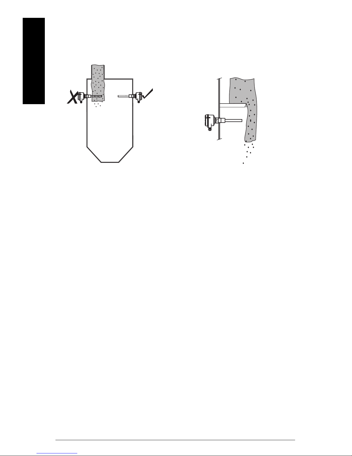
mmmmm
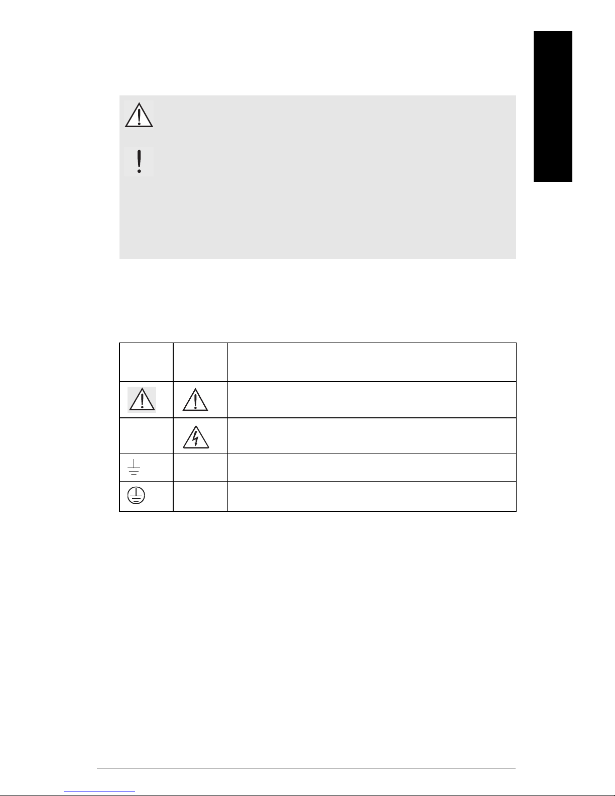
Cable gland faces
downward to avoid
water penetration.
Protection in case of
high material loading.
Use angle mounting for flowing
material only.
If angle mounting is required
with high material loading,
customer-supplied protection
from falling material must be in
place.
*
max. deviation
from vertical
max. length L
5º 4 m
45º 1.2 m
>45º 0.6 m
*
L
Tine orientation
marking facing
sideways.
Position tines vertically
to avoid product buildup: use a 50 mm openend wrench to turn the
process connection
until the tine
orientation marking
faces up or down.
Rigid extension with
sliding sleeve
Cable
extension
version
SITRANS LVS100/200 is normally mounted into the vessel top for full detection, or
through the tank wall at the detection level, for full, demand, or empty detection.
English
Page EN-10 SITRANS LVS100/200 – INSTRUCTION MANUAL 7ML19985FT63
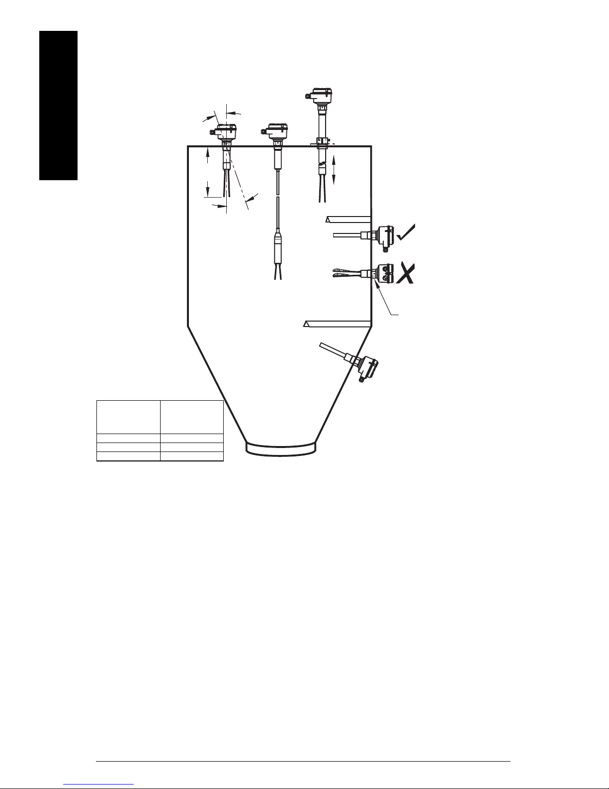
Temperature Isolator Option (LVS100/200)
$ installed without temperature
isolator, process connection at surface
% installed without temperature
isolator, process connection above
surface
& installed with temperature isolator
option
Installing SITRANS LVS100/200 with
the temperature extension allows the
device to be operated at higher
ambient temperatures, &, than would
be possible otherwise, $.
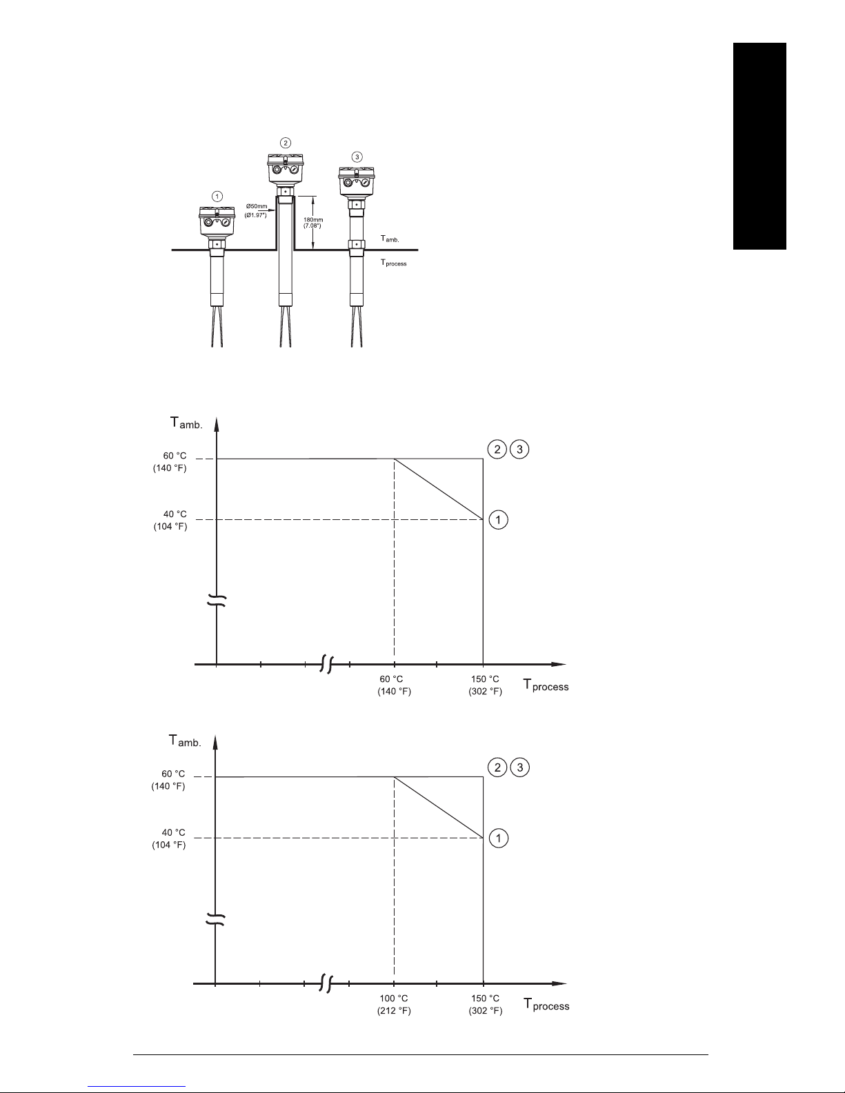
Process Temperature (LVS200)
Process Temperature (LVS100)
When installed with the temperature isolator option, SITRANS LVS100/200 can operate in
higher ambient temperatures.
English
mmmmm
7ML19985FT63 SITRANS LVS100/200 – INSTRUCTION MANUAL Page EN-11
mmmmm
Caution:
• Locate SITRANS LVS100/200
out of path of falling material
• Protect shaft and tines from falling
material
OR
Process Cautions
English
Page EN-12 SITRANS LVS100/200 – INSTRUCTION MANUAL 7ML19985FT63
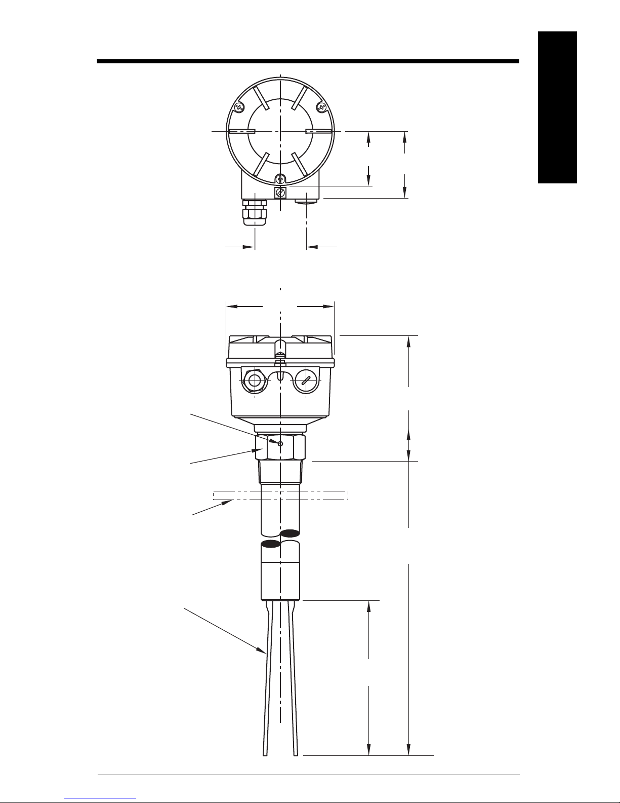
Dimensions - SITRANS LVS100
120 mm
(4.72")
150 mm
(5.91")
customer
supplied
process
flange
170 to 4000 mm (6.69 to 157"):
customer-specified rigid
extension
125 mm (4.92"):
standard fork
60 mm
(2.36")
60 mm
(2.36")
75 mm
(2.95")
tine
orientation
marking
Zone 21
ATEX Category 2D
IECEx EPL Db
Zone 20
ATEX Category 1D
IECEx EPL Da
threaded
bushing [max.
temp. +80°C
(+176°F)]
tine
English
mmmmm
7ML19985FT63 SITRANS LVS100/200 – INSTRUCTION MANUAL Page EN-13
mmmmm
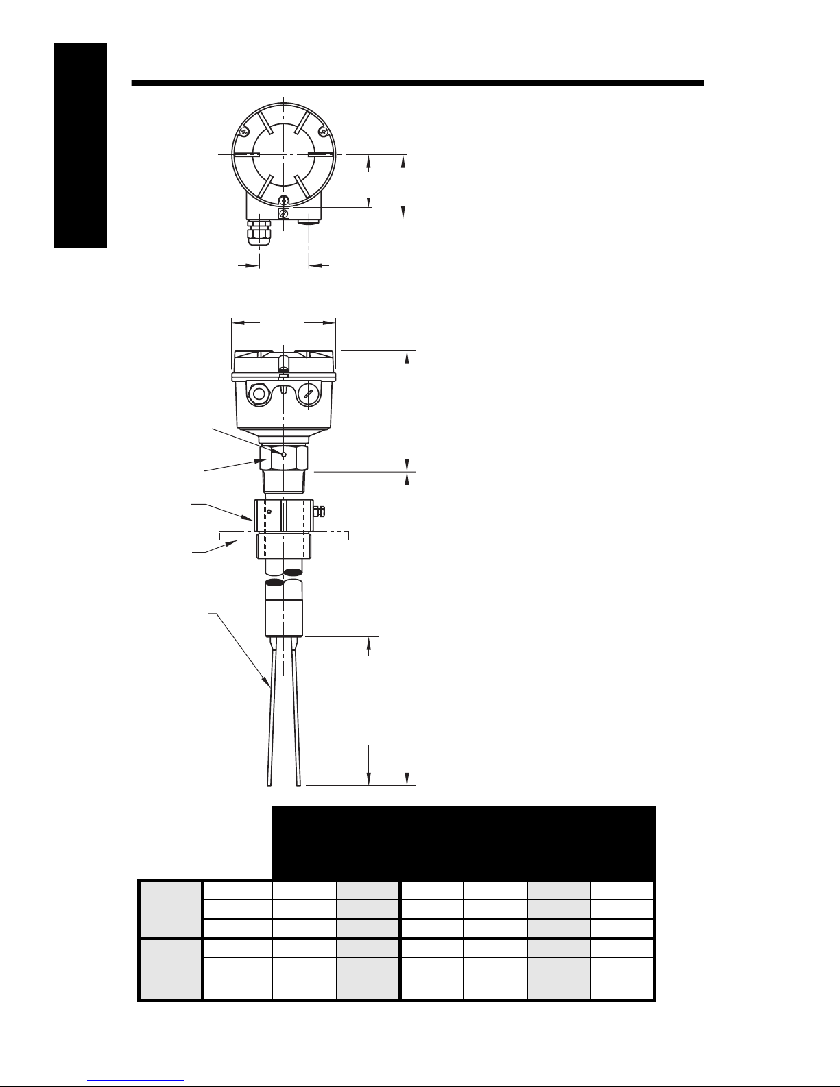
120 mm
(4.72")
150 mm
(5.91")
customer
supplied
process
flange
165 mm (6.5"): compact solids/liquids interface model
230 mm (9.0"):compact standard version
300 to 40 00 mm (11.81 to 157"): customer-specified rigid
extension
170 mm (6.69"):
standard fork
195 mm (7.68"):
low density fork
100 mm (3.94"):
liquid/solid
(short) fork
60 mm
(2.36")
60 mm
(2.36")
75 mm
(2.95")
tine
orientation
marking
**A
**B
threaded
bushing [max.
temp. +80°C
(+176°F)]
optional
sliding
bushing*
*Note: The clamping screws of the sliding bushing must
be tightened to 10 Nm.
tine
Universal voltage Relay SPDT
Universal Voltage Relay DPDT
3-wire PNP
2 wire without contact
8/16 mA or 4-20 mA
(non-intrisically safe)
NAMUR IEC 60945-5-6 (Intrinsically Safe)
8/16 mA or 4-20 mA (intrinsically safe)
**A
EPL (IECEx) Da Db Da Db Ga Gb
Category (ATEX) 1D
2D 1D 2D 1G 2G
Zone 20
21 20 21 01
**B
EPL (IECEx) Da Da Da Da Ga Ga
Category (ATEX)
1D 1D 1D 1D 1G 1G
Zone
20 20 20 20 00
Dimensions - SITRANS LVS200
English
Page EN-14 SITRANS LVS100/200 – INSTRUCTION MANUAL 7ML19985FT63
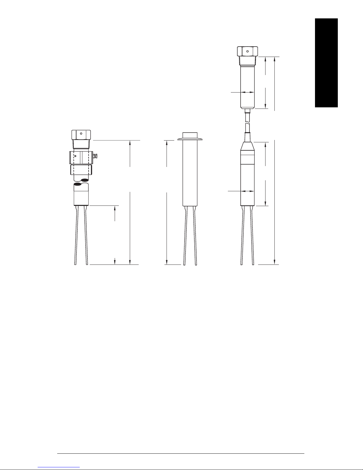
Dimensions (LVS200 Forks)
165 mm (6.5"): compact solids/liquids
interface model
230 mm (9.0"):compact standard version
300 to 4000 mm (11.81 to 157"): customerspecified rigid extension
170 mm (6.69"):
standard fork
195 mm (7.68"):
low density fork
100 mm (3.94"):
liquid/solid
(short) fork
195 mm
(7.68")
700 to
20 000 mm*
(27.56 to 787")
155 mm
(6.1")
ø 42 mm
(1.67")
ø 42 mm
(1.67")
Cable version
TriClamp version
Standard version
*Note: Cable version with Liquids/solids interface
model option length to 7000 mm (275.59")
Cable version with NAMUR electronics length to
10 000 mm (393.7")
English
mmmmm
7ML19985FT63 SITRANS LVS100/200 – INSTRUCTION MANUAL Page EN-15

Wiring
mmmmm
English
WARNINGS:
• Open SITRANS LVS100/200 only when supply voltage is switched off.
• All field wiring must have insulation suitable for at least 250 V AC.
• A disconnect switch must be in close proximity to the equipment and
within easy reach of the operator.
• Unused cable conduit fittings must be locked with a closing element or
plug.
• Observe all pertinent rules and regulations in the country of
installation.
Notes:
European requirements
• Cable gland/closing element: The screwed cable gland and closing element must have
the following specifications: Ingress protection IP66, temperature range from -40 to
70 °C (-40 to 158 °F), UL or VDE certified (depending on the country where the unit is
installated), pull relief.
Make sure the screwed cable gland safely seals the cable and that it is tight (danger of
water intrusion). Cable glands that are not used have to be locked with a closing
element.
•Conduit system: In case of using a conduit system (with NPT thread) instead of a cable
gland, the regulations of the coutnry where the unit is installed must be observed. The
conduit must have a tapered thread either ½" NPT or ¾" NPT in accordance with the unit
and ANSI B 1.20.1. Not used inlets must be closed tight with a metal closing element.
• Cable glands and conduit system for ATEX/IECEx (Dust and Gas Hazardous Locations):
Installation according to the regulations of the country where the unit is installed.
Not used entries have to be closed with blanking elements certified for this purpose.
Where available, the factory provided parts must be used.
A strain relief must be provided for the field wiring cables, when the device is installed
with the facotry provided cable glands.
The diameter of the field wiring cable must match to the clamping range of the cable
clamp.
If other than the factory provided parts are used, the following must be ensured:
• The parts must have an approval adequate to the approval of the level sensor
(certificate and type of protection).
• The approved temperature range must be from the min. ambient temperature of
the level sensor to the max. ambient temperature of the level sensor increased
by 10K.
• The parts must be mounted according to the instructions of the supplier.
• Conduit systems for FM and CSA (Dust and Gas Hazardous Locations):
General requirements: In addition the regulations of the country must be observed. The
used flameproof seals and blanking elements must have an adequate type approval and
a temperature range of at least -40 to 80 °C (-40 to 176 °F). In addition, they shall be
suitable for the conditions and correctly installed. Where available, the provided original
parts of the manfacturer must be used.
Page EN-16 SITRANS LVS100/200 – INSTRUCTION MANUAL 7ML19985FT63
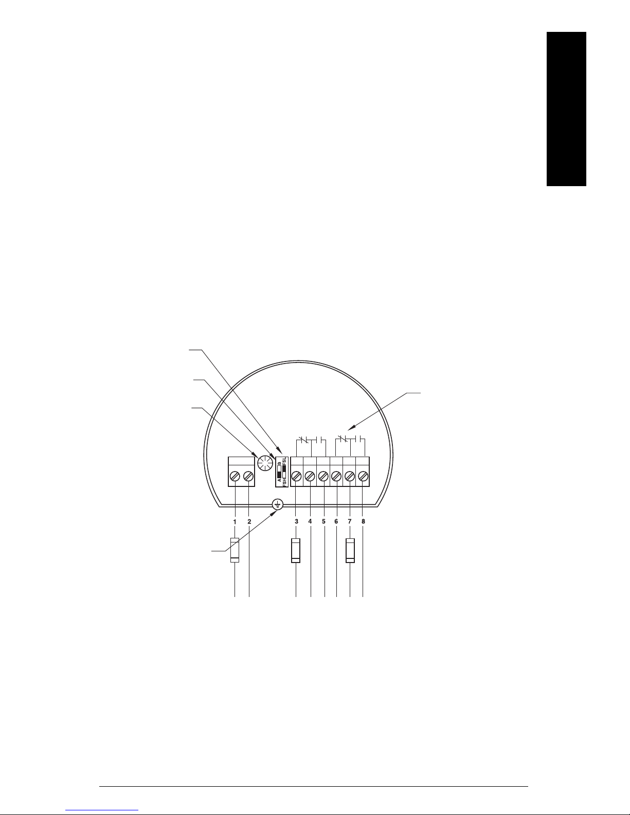
Connection recommendations
alarm output relays
FSH/FSL adjustment
sensitivity adjustment
B = factory setting,
A = decreased sensitivity
AC: terminal 1: L
terminal 2: N
19 to 230 V AC, ± 10 %,
50 to 60 Hz, 22 VA
DC: terminal 1: +
terminal 2: 19 to 40 V DC, ± 10 %, 2 W
LED
protective
earth
terminal
fuses: max. 10 A, fast or slow,
HBC, 250 V
• Use a fuse for the signal output (max. 10 A).
• Provide protection for relay contacts to protect the device against spikes if inductive
loads are connected.
Precautions
• Before opening the lid, ensure there are no dust deposits around
SITRANS LVS100/200, and that the atmosphere around the instrument is settled.
• Make sure the main voltage does not exceed the maximum voltage listed on the
product label.
• Ensure that no more than 8 mm of each wire is stripped (to avoid danger of contact
with live parts).
• Ensure the boots for protecting cable terminations are no longer than 8 mm (to avoid
danger of contact with live parts).
• For installation of the 3-wire PNP electronics (Protection Class III), the insulation of
the connected power supply and output load must meet the relevant standards.
Universal voltage (DPDT relay)
(LVS100)
English
mmmmm
7ML19985FT63 SITRANS LVS100/200 – INSTRUCTION MANUAL Page EN-17
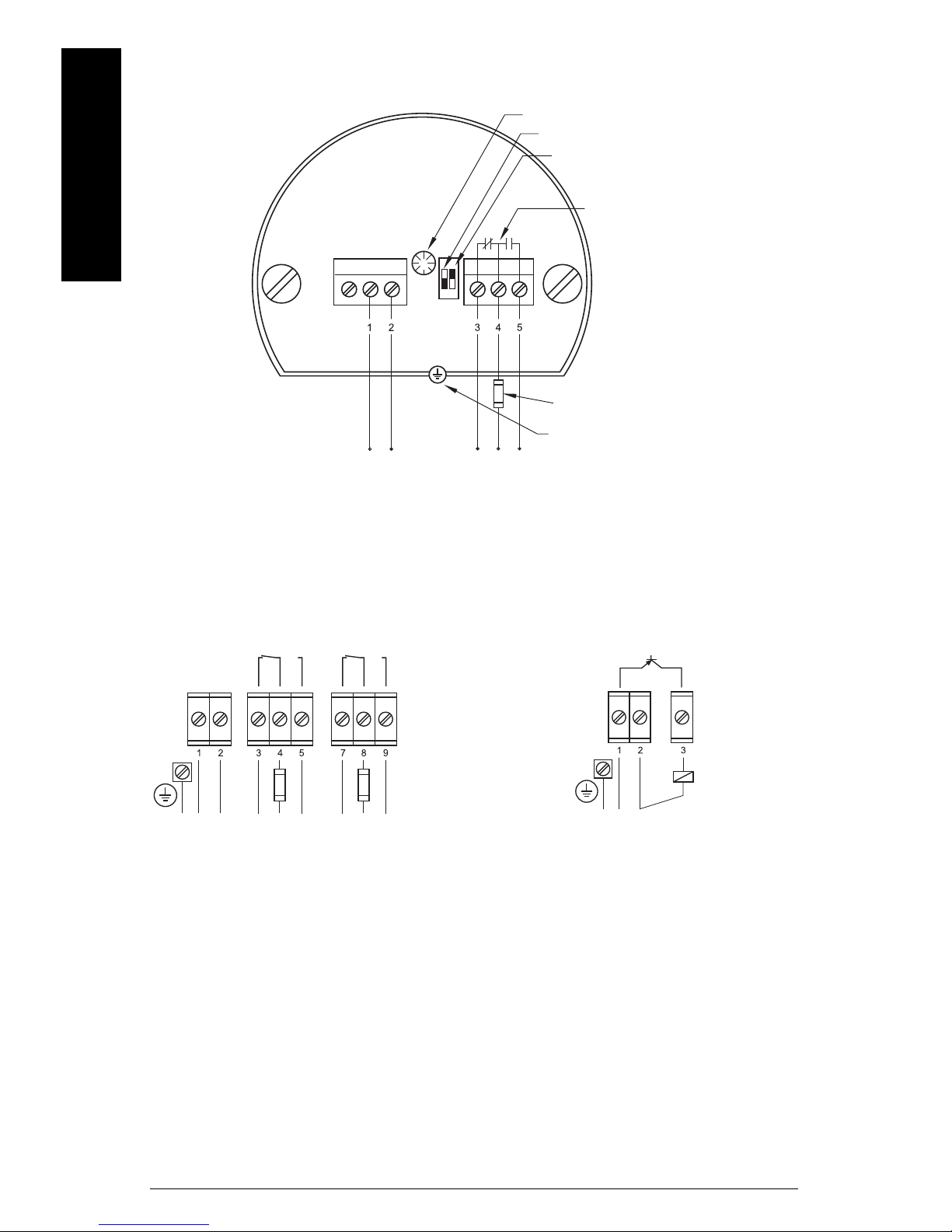
mmmmm
alarm output relay
FSH/FSL adjustment
sensitivity adjustment
B = factory setting,
A = decreased sensitivity
AC: terminal 1: L
terminal 2: N
19 to 230 V AC, + 10 %, 50 to 60 Hz, 18 VA
DC: terminal 1: +
terminal 2: -
19 to 55 V DC, + 10 %, 1.5 W
protective earth terminal
A
B
FSH
FSL
LED
fuses: max. 10 A, fast or slow,
HBC, 250 V
PE
+
L
N
alarm output relays
PE
+
-
load
AC: terminal 1: L
terminal 2: N
19 to 230 V AC, + 10 %, 50 to 60 Hz, 18 VA
DC: terminal 1: +
terminal 2: 19 to 55 V DC, + 10 %, 2 W
DC: terminal 1: +
terminal 2: 18 to 50 V DC, + 10 %, 1.5 W
fuses: max. 10 A, fast
or slow, HBC, 250 V
Universal voltage (SPDT relay)
(LVS200)
English
Universal voltage (DPDT relay) 3-wire PNP
(LVS200) (LVS200)
Page EN-18 SITRANS LVS100/200 – INSTRUCTION MANUAL 7ML19985FT63
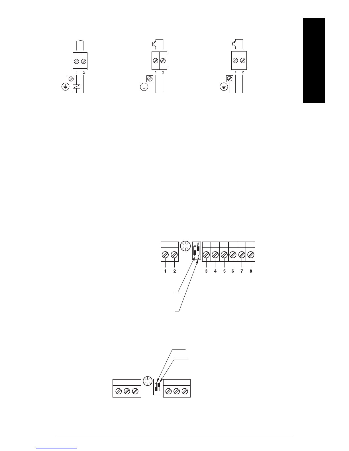
2-wire NAMUR IEC 60947-5-6 8/16 mA or 4 to 20 mA
PE
+
L
N
PE
+
-
PE
+
-
AC: terminal 1: L
terminal 2: N
19 to 230 V AC, + 10 %,
50 to 60 Hz, 1.5 VA
DC: terminal 1: +
terminal 2: 19 to 230 V DC, + 10 %, 1 W
ca. 7 to 9 V DC,
intrinsically safe
(IEC 60947-5-6)
DC: terminal 1: +
terminal 2: -
12.5 to 36 V DC, + 0 %
sensitivity adjustment:
B = factory setting
A = decreased sensitivity
FSH/FSL adjustment or
High/Low Alarm setting
FSH/FSL adjustment or
High/Low Alarm setting (NAMUR)
sensitivity adjustment:
B = factory setting
A = decreased sensitivity
FSH
FSL
A
B
(LVS200) (LVS200) (LVS200)
Sensitivity
English
mmmmm
If the measured material tends to cake or build up, the sensitivity adjustment switch can
be set to position A to decrease the sensitivity of the probe (factory setting is position B).
The sensitivity for interface applications should be set to position B, while the setting for
high-flow applications should be position A.
LVS100
LVS200
7ML19985FT63 SITRANS LVS100/200 – INSTRUCTION MANUAL Page EN-19
mmmmm
7
6
5
4
3
8
8
7
6
5
4
3
3
4
5
3
4
5
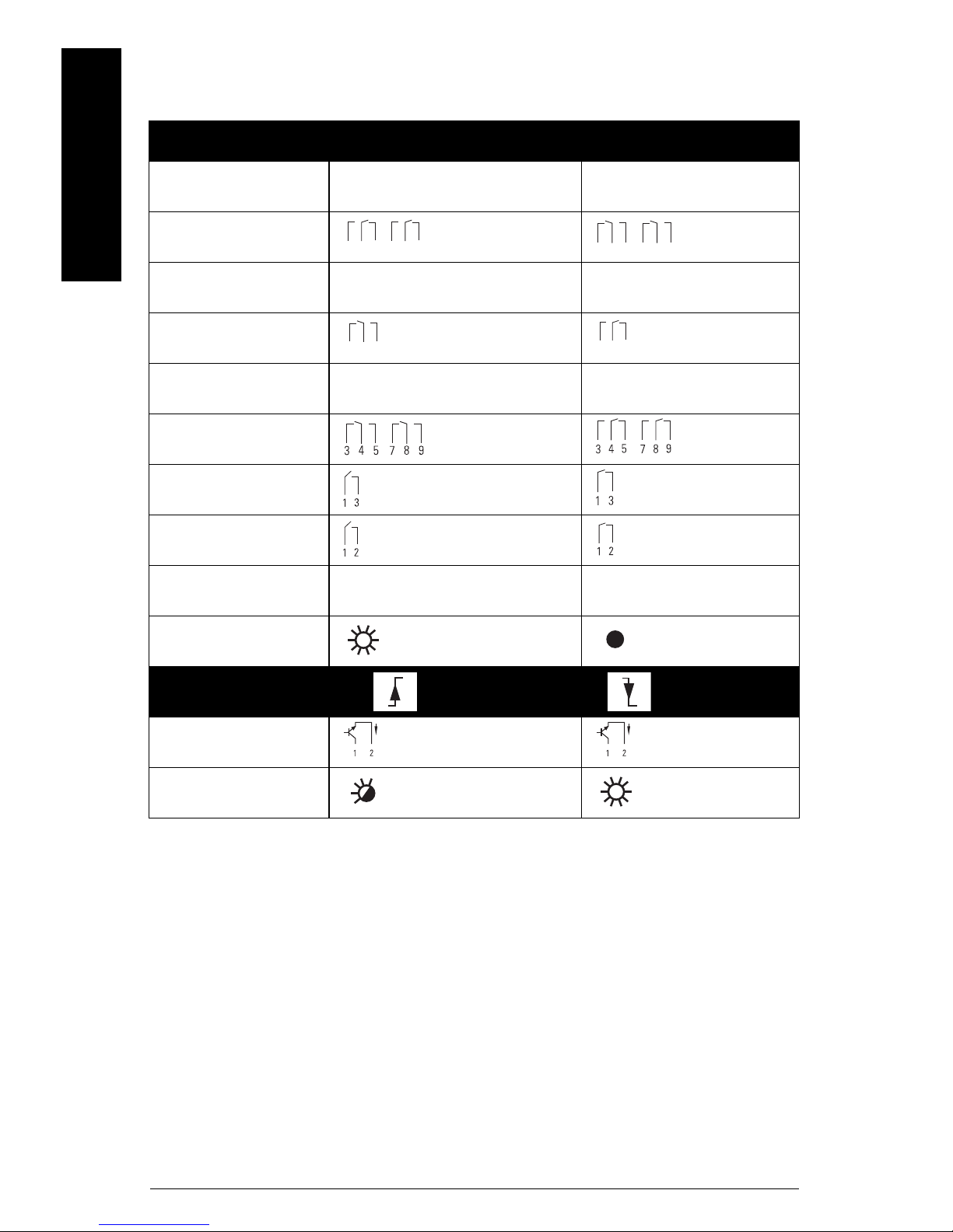
Switching Logic
Probe uncovered
Model Failsafe low Failsafe high
English
LVS10 0
DPDT relay
LVS20 0
SPDT relay
LVS20 0
DPDT relay
3-wire PNP
Signal Output
2-wire
8/16 mA I = 16 mA I = 8 mA
Signal Output LED
Low alarm setting High alarm setting
NAMUR IEC
60947-5-6
I < 1 mA I > 2.2 mA
Signal Output LED
Page EN-20 SITRANS LVS100/200 – INSTRUCTION MANUAL 7ML19985FT63
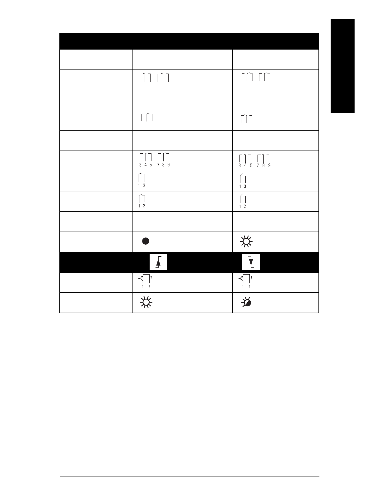
Probe covered
8
7
6
5
4
3
7
6
5
4
3
8
3
4
5
3
4
5
Signal Output
Model Failsafe low Failsafe high
LVS10 0
DPDT relay
LVS20 0
SPDT relay
LVS20 0
DPDT relay
3-wire PNP
2-wire
English
mmmmm
8/16 mA I = 8 mA I = 16 mA
Signal Output LED
Low alarm setting High alarm setting
NAMUR IEC
60947-5-6
I >2.2 mA I < 1 mA
Signal Output LED
7ML19985FT63 SITRANS LVS100/200 – INSTRUCTION MANUAL Page EN-21
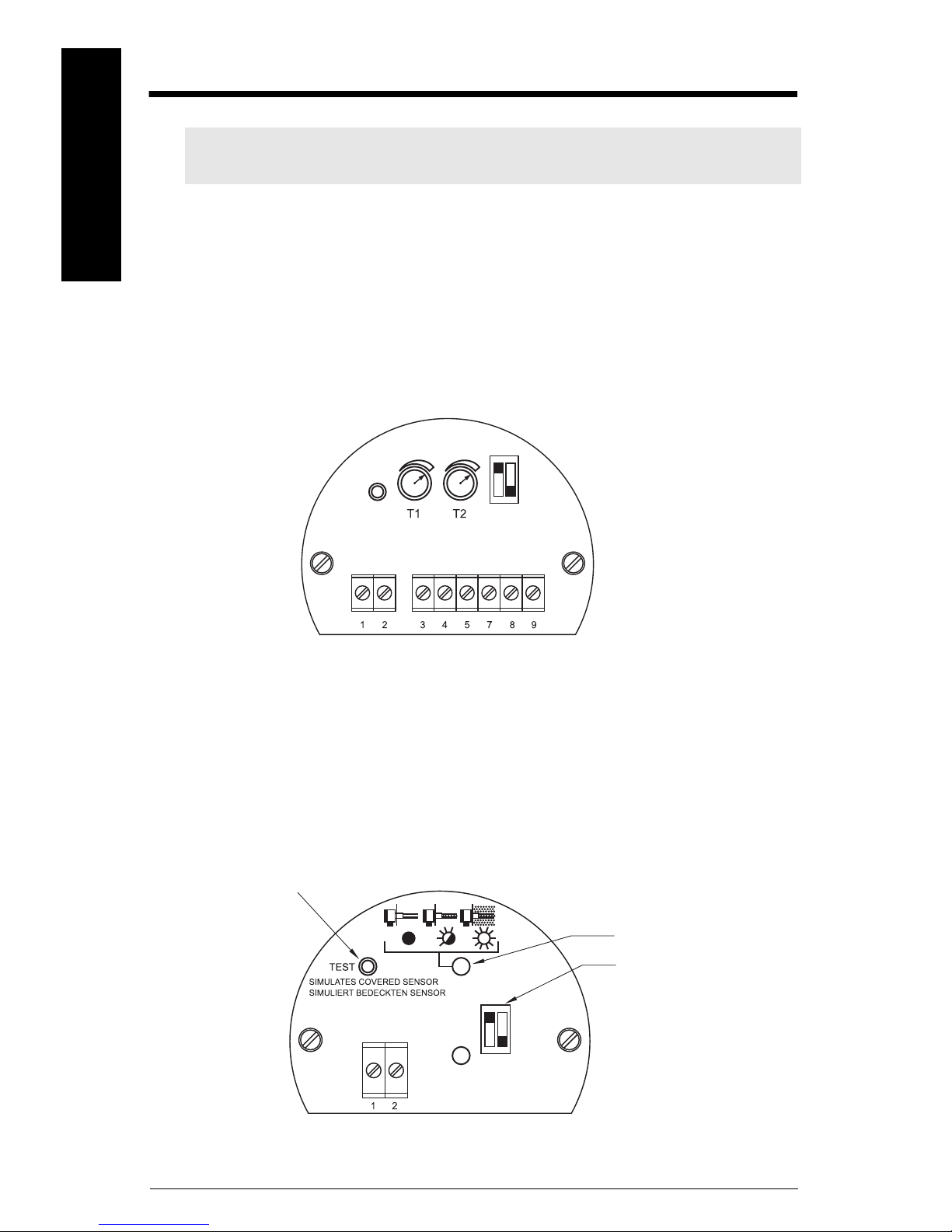
mmmmm
Test button
Electronic module
diagnostic LED
NAMUR model
sensitivity adjustment:
B = factory setting
A = decreased sensitivity
A
B
Signal output and test options (LVS200)
Note: The signal output and test options listed below apply only to specific power
supply options.
English
Signal Output Delay
Universal voltage (DPDT) model
The signal output can be delayed and is adjustable from 0 to 30 seconds. Turn the
potentiometer clockwise to increase the delay time.
Potentiometer T1: Delay when output switches from fork covered to uncovered.
Potentiometer T2: Delay when output switches from fork uncovered to covered.
Test function
NAMUR model (IEC 60947-5-6) and 8/16 mA or 4 to 20 mA model
If the fork is uncovered, pressing this button will stop the vibration and the signal output
will switch to indicate a covered fork. You can test the vibration and the electronics
without removing the LVS200 from the vessel. If the fork is covered, pressing the button
has no effect.
Page EN-22 SITRANS LVS100/200 – INSTRUCTION MANUAL 7ML19985FT63
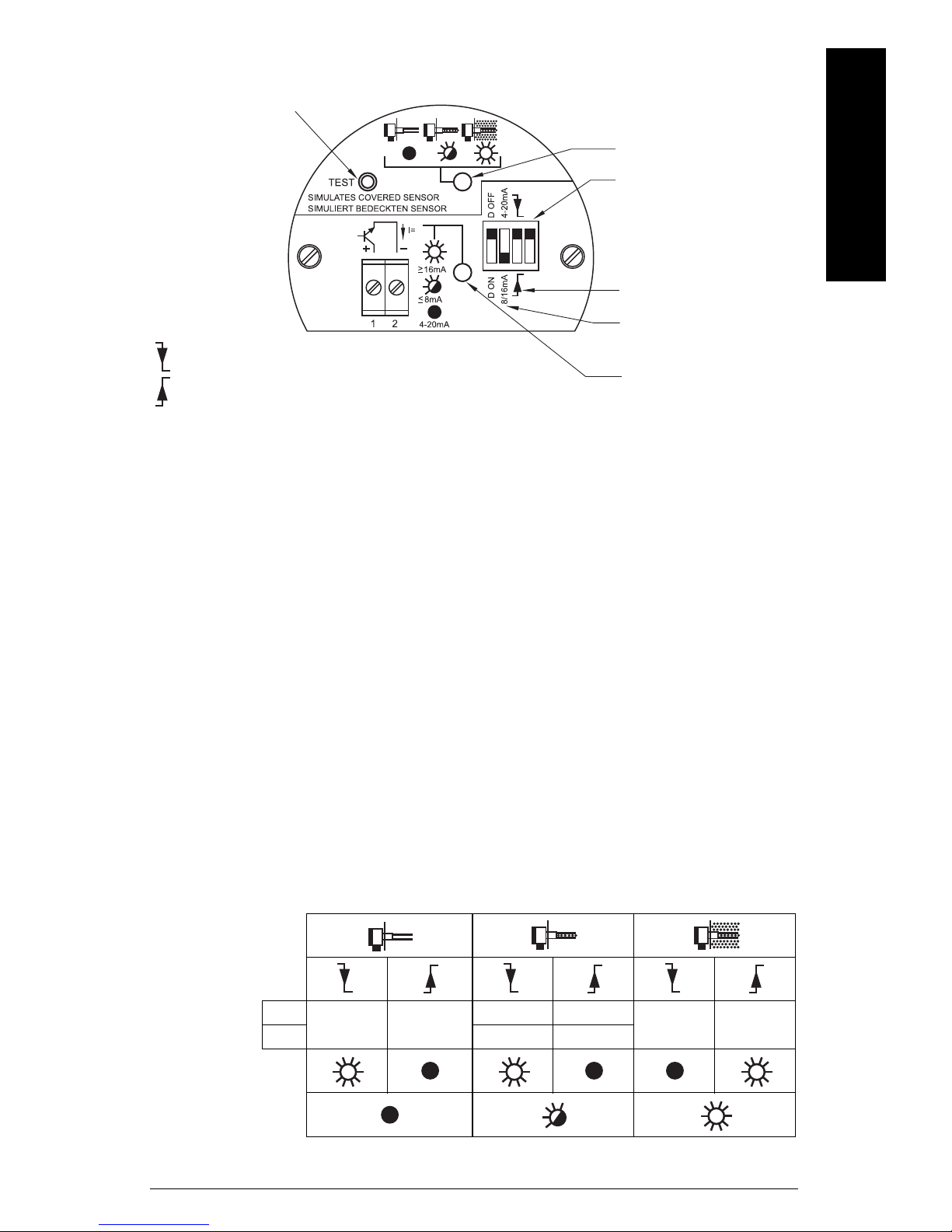
Vibration amplitude diagnosis
8/16 or 4 to 20 mA model
Test butt on
diagnostic LED
sensitivity adjustment:
B = factory setting
A = decreased sensitivity
B
A
filling or emptying
output setting
signal output LED
Sensor switches at high level
Fail-safe function will default to full signal
Sensor switches at low level
Fail-safe function will default to empty signal
NAMUR module (IEC 60947-5-6) and and 8/16 mA or 4 to 20 mA model
Measurement quality is related to the vibration amplitude of the fork. The diagnostic LED
indicates the quality of the vibration being sent to the LVS200 electronics.
English
mmmmm
• Diagnostic LED off: measurement quality is good. The vibration amplitude is strong.
• Diagnostic LED blinking: measurement quality is poor and vibration amplitude is
decreasing as fork becomes encrusted. When this happens, set the sensitivity
switch to decreased sensitivity.
• Diagnostic LED on: vibration has stopped and fork is fully encrusted with material.
Current output setting
8/16 mA
The chart below illustrates the output current when:
•Fork is clean
• Fork is encrusted: weak vibration amplitude is shown
• Fork is fully encrusted and vibration has stopped.
Diagnosis
Setting
Signal
output LED
Diagnosis
LED
D Off
D On I = 20 mA I = 6 mA
7ML19985FT63 SITRANS LVS100/200 – INSTRUCTION MANUAL Page EN-23
I = 16 mA I = 8 mA
I = 16 mA I = 8 mA
I = 8 mA I = 16 mA
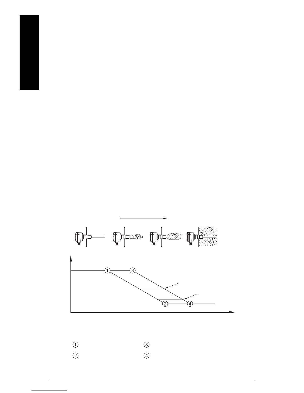
mmmmm
increasing material buildup
Amplitude is 100%
Amplitude is 0%
Amplitude is 100%
Amplitude is 0%
With standard sensitivity setting
With decreased sensitivity setting
6 mA
7/8 mA
12/12.5 mA
20 mA
output current
s
t
a
n
d
a
r
d
s
e
n
s
i
t
i
v
i
t
y
d
e
c
r
e
a
s
e
d
s
e
n
s
i
t
i
v
i
t
y
Vibration damping by material
The output current can indicate weak vibration amplitude with the diagnosis setting D
ON. If the diagnosis is set to D OFF, the output will be either 8 mA or 16 mA depending on
high or low level settings.
If the diagnosis is set to D ON, the output will change from 16 to 20 mA and from 8 to 6 mA
if the vibration is weak. This output can be passed to an external 4 to 20 mA output. There
English
is an internal delay of 10 seconds before the change happens, so that the external output
does not indicate a weak vibration when the vibration is stopped and started during
normal measurement operation.
Buildup Detection (8/16 mA or 4 to 20 mA version)
With the 4 to 20 mA setting, you can recognize material buildup on the fork using a PLC or
data logger.
In this mode, the Diagnostic setting has no influence. The LED showing signal output is
off.
20 mA: The fork is clean.
<20 mA and >12/12.5 mA: The vibration amplitude is decreased by the material buildup.
<12/12.5 mA and >7/8 mA: This range indicates a weak vibration. The internal LED
showing diagnosis begins blinking to indicate a weak signal. If you are using a PLC to
evaluate the echo, delay the response time to this indicator for approximately 10 seconds.
A hysteresis of 0.5 mA (between 12 and 12.5 mA) is recommended.
7/8 mA: This point indicates that the fork is mostly encrusted.
6 mA: This point indicates that the fork is fully encrusted.
Page EN-24 SITRANS LVS100/200 – INSTRUCTION MANUAL 7ML19985FT63

Maintenance
SITRANS LVS100/200 require no maintenance or cleaning under normal operating
conditions. Under severe operating conditions, the tines may require periodic cleaning.
Brush off any accumulated deposits, taking care not to bend the tines.
Unit Repair and Excluded Liability
All changes and repairs must be done by qualified personnel, and applicable safety
regulations must be followed. Please note the following:
• The user is responsible for all changes and repairs made to the device.
• All new components must be provided by Siemens Milltronics Process Instruments Inc.
• Restrict repair to faulty components only.
• Do not re-use faulty components.
English
mmmmm
7ML19985FT63 SITRANS LVS100/200 – INSTRUCTION MANUAL Page EN-25
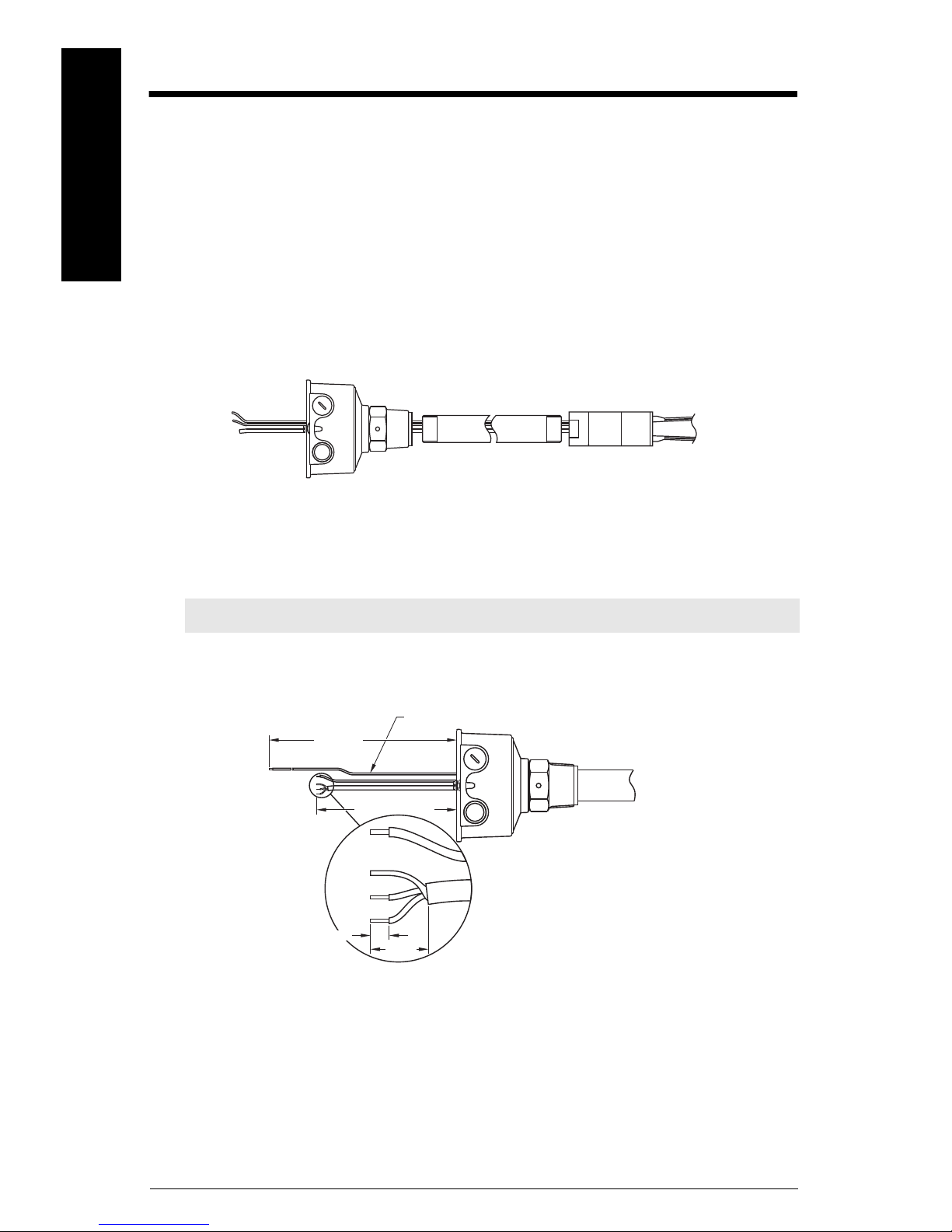
SITRANS LVS200 Pipe Extended Version
enclosure
customer supplied
pipe extension
fork assembly
earth cable (green/yellow)
220 mm
(8.7")
150 mm (5.9")
8 mm max.
18 mm
mmmmm
Assembly
English
Suggested tools:
• medium Phillips or 6 to 8 mm (¼”) flat screwdriver • terminal crimper
• 3 mm (1/8”) flat screwdriver • 36 mm open end wrench
• wire cutters • pipe wrench
•wire strippers
1. Open the enclosure lid; remove electronics module.
2. Lead the sensor cable through the customer supplied 1" tube and enclosure.
3. Assemble the fork assembly, the pipe extension, and the enclosure using the 36 mm
open end wrench. Seal the pipe threads with an appropriate sealant.
Note: Do not turn fork assembly. Do not bend the fork during assembly.
4. Line up the fork and the tine orientation marking as shown in dimension drawing on
page 16. (The tine orientation marking on the process connection is to identify the
vertical orientation of the fork.)
5. Shorten sensor cable to a free length of 150 mm (5.9").
6. Shorten earth cable to a free length of 220 mm (8.7").
7. Prepare sensor cable as shown above, stripping a maximum of 8 mm from each
wire.
Page EN-26 SITRANS LVS100/200 – INSTRUCTION MANUAL 7ML19985FT63
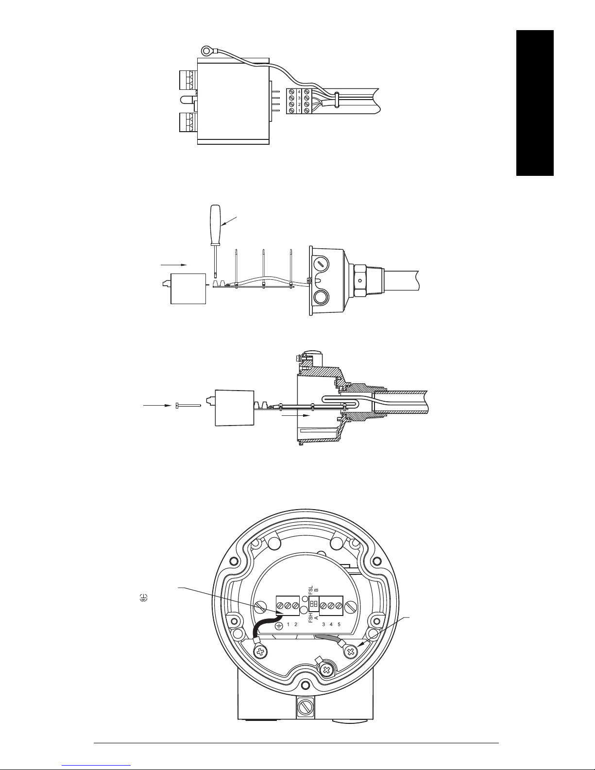
8. Connect the sensor cable to the terminal connection board shown above.
electronics
module, flat
side up
4 = BLACK (T)
3 = SHIELD (M)
2 = RED (R-)
1 = WHITE (R+)
3 mm (1/8”) screw driver
cable ties
Connect protection earth
of the enclosure to
terminal of the
electronics module.
Connect earth cable
of the fork to the
electronics earth
terminal.
9. Secure the sensor cable with cable ties.
10. Crimp the ring terminal 4 mm (0.19") to sensor earth cable.
11. Connect electronics module and terminal connection board. Be sure that all
terminals are tight.
English
mmmmm
12. Insert the electronics module into the housing. The terminal connection board is
used to guide the cable into the extension tube.
13. Fold cable as shown in diagram above.
14. Secure the electronics module as shown in diagram below.
7ML19985FT63 SITRANS LVS100/200 – INSTRUCTION MANUAL Page EN-27
mmmmm
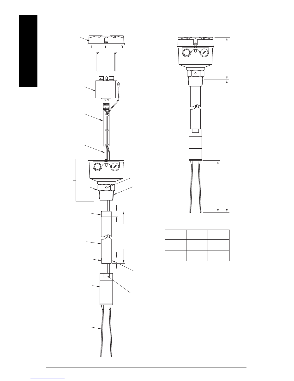
½” NPT
M20x1.5
1½”NPT
1 ½" BSPT
1" NPT
G1"
lid
electronics module
terminal connection
board
sensor cable
enclosure
assembly
process
connection
tine orientation marking
process thread 1 ½” NPT
(taper) or
R 1 ½” (BSPT)
thread G1” or 1" NPT
(use appropriate
thread sealant)
fork
fork assembly
thread G1” or 1" NPT
(use appropriate
thread sealant)
1" schedule 40 pipe
(internal min.
dia. 25.4 mm (customer
supplied and mounted)
X = L - 255 mm
(10")
min.
18 mm
(0.75")
min.
18 mm
(0.75")
SW 36
Note: Threaded
engagement to be a
min. of 7 mm (0.27")
approx.
138 mm
(5.4")
L = 300 to 3800 mm
(11.8 to 149.6")
170 mm
(6.7")
process
thread
cable
entries
1" pipe
thread
Assembly Overview Drawing
English
Page EN-28 SITRANS LVS100/200 – INSTRUCTION MANUAL 7ML19985FT63
 Loading...