

Siemens SITRANS LUT400 User Manual

Communications
For SITRANS LUT400 (HART)
Manual 02/2014

Safety Guidelines: Warning notices must be observed to ensure personal safety as well as that of
others, and to protect the product and the connected equipment. These warning notices are
accompanied by a clarification of the level of caution to be observed.
Qualified Personnel: This device/system may only be set up and operated in conjunction with this
manual. Qualified personnel are only authorized to install and operate this equipment in accordance with
established safety practices and standards.
Unit Repair and Excluded Liability:
The user is responsible for all changes and repairs made to the device by the user or the user’s
agent.
All new components are to be provided by Siemens Milltronics Process Instruments.
Restrict repair to faulty components only.
Do not reuse faulty components.
Warning: Cardboard shipping package provides limited humidity and moisture protection. This product
can only function properly and safely if it is correctly transported, stored, installed, set up, operated, and
maintained.
This product is intended for use in industrial areas. Operation of this equipment in a residential area
may cause interference to several frequency based communications.
Note: Always use product in accordance with specifications.
Copyright Siemens AG 2013. All Rights
Disclaimer of Liability
Reserved
This document is available in bound version and in
electronic version. We encourage users to purchase
authorized bound manuals, or to view electronic
versions as designed and authored by Siemens
Milltronics Process Instruments. Siemens Milltronics
Process Instruments will not be responsible for the
contents of partial or whole reproductions of either
bound or electronic versions.
While we have verified the contents of this
manual for agreement with the
instrumentation described, variations remain
possible. Thus we cannot guarantee full
agreement. The contents of this manual are
regularly reviewed and corrections are
included in subsequent editions. We welcome
all suggestions for improvement.
Technical data subject to change.
MILLTRONICS®is a registered trademark of Siemens Milltronics Process Instruments.
Contact SMPI Technical Publications European Authorized Representative
at the following address:
Technical Publications Siemens AG
Siemens AG Industry Sector
Siemens Milltronics Process Instruments 76181 Karlsruhe
1954 Technology Drive, P.O. Box 4225 Deutschland
Peterborough, Ontario, Canada, K9J 7B1
Email: techpubs.smpi@siemens.com
For a selection of Siemens Milltronics level measurement manuals, go to:
www. siemens.com/processautomation. Under Process Instrumentation, select
Measurement
For a selection of Siemens Milltronics weighing manuals, go to:
www. siemens.com/processautomation. Under Weighing Technology, select
Weighing Systems
and then go to the manual archive listed under the product family.
and then go to the manual archive listed under the product family.
Level
Continuous
© Siemens AG 2013

Table of Contents
Table of Contents ...............................................................................................................i
Introduction ........................................................................................................................1
Overview .................................................................................................................................................1
Safety Notes ...........................................................................................................................................1
The Manual ............................................................................................................................................1
Technical Support .................................................................................................................................2
Service & Support on the Internet ..........................................................................................2
Additional Support ......................................................................................................................2
Abbreviations and Identifications ...........................................................................................3
Operation via SIMATIC PDM 6 (HART) ..........................................................................5
Features .........................................................................................................................................5
Functions .......................................................................................................................................5
SIMATIC PDM version ...............................................................................................................6
Electronic Device Description (EDD) ......................................................................................6
Configuring a new device .........................................................................................................7
Quick Start Wizard via SIMATIC PDM ...................................................................................7
Quick Start (Level)............................................................................................................. 9
Quick Start (Volume)....................................................................................................... 12
Quick Start (Volume - Linearization)........................................................................... 15
Quick Start (Flow)............................................................................................................ 19
Pump Control Wizard ...............................................................................................................22
Changing parameter settings using SIMATIC PDM .........................................................24
Parameters accessed via pull-down menus ......................................................................25
Set Address ................................................................................................................................27
Echo Profile Utilities .................................................................................................................27
Maintenance ..............................................................................................................................32
Process Variables .....................................................................................................................36
Operation via Web Browser (USB) ..............................................................................41
Features .......................................................................................................................................41
Functions .....................................................................................................................................41
Installation ..................................................................................................................................41
Installing the USB driver................................................................................................ 41
Installing the web browser interface ......................................................................... 42
Accessing the device via the web browser .......................................................................43
Changing parameter settings using the browser .............................................................45
Configuring a new device .......................................................................................................45
Browser Menu Parameter Function Groups ......................................................................46
Operation via AMS Device Manager (HART) .............................................................49
Features .......................................................................................................................................49
Functions .....................................................................................................................................49
Electronic Device Description (EDD) ....................................................................................50
Configuring a new device .......................................................................................................50
Startup .........................................................................................................................................50
Master Reset.................................................................................................................... 52
Pull-down menu access................................................................................................ 52
Table of Contents
i

Scan Device...................................................................................................................... 52
Device configuration ................................................................................................................53
Quick Start Wizards via AMS Device Manager ................................................................54
Wizard - Quick Start (Level).......................................................................................... 55
Wizard - Quick Start (Volume)...................................................................................... 57
Wizard - Quick Start (Volume - Linearization).......................................................... 60
Wizard - Quick Start (Flow)........................................................................................... 63
Table o f C on t en t s
Changing parameter settings using AMS Device Manager ..........................................68
Device Diagnostics View ........................................................................................................75
Process Variables View ..........................................................................................................76
Password Protection ................................................................................................................76
User Manager Utility ................................................................................................................77
AMS Menu Structure ..............................................................................................................78
Operation via Field Communicator
375/475 (FC375/FC475) (HART) .......................................................................................97
Features .......................................................................................................................................97
Functions .....................................................................................................................................97
Configuring a new device .......................................................................................................97
HART FC375/FC475 Menu Structure .....................................................................................98
Operation via FDT (Field Device Tool) .......................................................................133
Features .....................................................................................................................................133
Functions ...................................................................................................................................133
Device Type Manager (DTM) ...............................................................................................133
SITRANS DTM version 3.1 ......................................................................................... 133
Electronic Device Description (EDD) ..................................................................................133
Configuring a new device .....................................................................................................133
ii

Introduction
Overview
The SITRANS LUT400 ultrasonic controller may be operated via remote communications,
using various PC software such as:
• SIMATIC PDM
• Web Browser Interface (used with Web Server Abyss - provided for your
convenience)
• AMS Device Manager
• Field Communicator 375/475 (FC375/FC475) (HART)
• A Field Device Tool (FDT), such as PACTware or Fieldcare
Please consult the appropriate manufacturer’s operating instructions for general details
on how to operate each software package.
Safety Notes
Special attention must be paid to warnings and notes highlighted from the rest of the text
by grey boxes.
Note: means important information about the product or that part of the operating
manual.
The Manual
This manual provides information on the use of SITRANS LUT400 with various remote
communications software packages noted above. The manual is designed to help you get
the most out of your ultrasonic device when used in conjunction with a remote
communications tool. It provides information for the various tools in the following areas:
COMMS LUT400
• Features and Functions
• Installation, Startup, and Configuration of the SITRANS LUT400
• Quick Start Wizards and Pump Control Wizards
• Changing parameters
• Parameter menus
This manual should be used in conjunction with the SITRANS LUT40 0 (HART) Operating
Instructions (7ML19985MV01)
for optimum performance. We always welcome suggestions and comments about
manual content, design, and accessibility. Please direct your comments to
techpubs.smpi@siemens.com
For other Siemens level measurement manuals, go to:
www.siemens.com/level
1.
See DVD shipped with device or download manual from product page of our
website: Go to www.siemens.com/sitransLUT400 > Technical Info > Manuals/
Operating instructions.
A5E33701270 COMMUNICATIONS FOR SITRANS LUT400 (HART) – MANUAL Page 1
1
to help you set up your device via remote communications
.
, and look under Level Measurement.

Technical Support
If you have any technical questions about the device described in these Operating
Instructions and do not find the answers, you can contact Customer Support:
• Via the Internet using the Support Request:
Support request (http://www.siemens.com/automation/support-request
• Via Phone:
• Europe: +49 (0) 911 895 7222
• America: +1 423 262 5710
• Asia-Pacific: +86 10 6475 7575
Further information about our technical support is available on the Internet at
Technical support (http://support.automation.siemens.com/WW/view/en/16604318
Service & Support on the Internet
In addition to our documentation, we offer a comprehensive knowledge base online on
COMMS LUT400
the Internet at:
Service & Support (http://www.siemens.com/automation/service&support
There you will find:
• The latest product information, FAQs, downloads, tips and tricks.
• Our newsletter, providing you with the latest information about our products.
• Our bulletin board, where users and specialists share their knowledge worldwide.
• Your local contact partner for Industry Automation and Drives Technologies in our
partner database.
• Information about field service, repairs, spare parts and lots more under "Services".
)
)
)
Additional Support
Please contact your local Siemens representative and offices if you have additional
questions about the device.
Find your contact partner at:
Local contact person (http://www.siemens.com/automation/partner
Page 2 COMMUNICATIONS FOR SITRANS LUT400 (HART) – MANUAL A5E33701270
)

Abbreviations and Identifications
Short
form
AMS Emerson AMS Device Manager
DD See EDD
DTM Device Type Manager
EDD Electronic Device Description (also referred to as DD)
FC Field Communicator 375/475
FDT Field Device Tool
LCD Liquid Crystal Display
LUI Local User Interface
PDM SIMATIC Process Device Manger
PMD Primary Measuring Device
PV Primary Value measured value
USB Universal Serial Bus
Long Form Description
software package used to
commission and maintain
SITRANS LUT400
a type of software that ’plugs
into’ a Field Device Tool (FDT).
HART device used to
commission and maintain
SITRANS LUT400
a standard used in software
packages designed to
commission and maintain field
devices such as SITRANS
LUT400
software package used to
commission and maintain
SITRANS LUT400
COMMS LUT400
A5E33701270 COMMUNICATIONS FOR SITRANS LUT400 (HART) – MANUAL Page 3

COMMS LUT400
Notes
Page 4 COMMUNICATIONS FOR SITRANS LUT400 (HART) – MANUAL A5E33701270

Operation via SIMATIC PDM 6 (HART)
(SITRANS LUT400 compatible with PDM version 6.1)
Features
SIMATIC PDM is a software package used to commission and maintain SITRANS LUT400 and
other process devices. Please consult the LUT400 online help for details on using SIMATIC
PDM. (More information can be found at www.siemens.com/simatic-pdm
SIMATIC PDM monitors the process values, alarms and status signals of the device. It allows
you to display, compare, adjust, verify, and simulate process device data; also to set schedules
for calibration and maintenance.
Functions
Notes:
• For a complete list of parameters, see
operating instructions1.
• While the device is in PROGRAM MODE, the output remains active and
continues to respond to changes in the device.
Parameters are identified by name and organized into function groups. The menu
structure for SIMATIC PDM is almost identical to that of the SITRANS LUT400 LCD. See
LCD Menu Structure
in chart format.
in LUT400 operating instructions1 for a complete list of parameters
Parameter reference (LUI)
.)
in LUT400
Operation - PDM
For a list of parameters that do not appear in the menu structure and are accessed via pulldown menus in SIMATIC PDM see page 26. See also
SIMATIC PDM
on page 24 for more details.
Changing parameter settings using
Feature page Function
Quick Start (Level) 9 Device configuration for simple level applications
Quick Start (Volume) 12
Quick Start (Volume - Linearization)
Quick Start (Flow) 19 Device configuration for simple flow applications
Pump Control Wizard 22 Pump control setup
Echo Profile Utilities 27 Echo profile viewing/comparison
1.
SITRANS LUT400 (HART) Operating Instructions (7ML19985MV01)
A5E33701270 COMMUNICATIONS FOR SITRANS LUT400 (HART) – MANUAL Page 5
Device configuration for simple volume
applications
Device configuration for volume applications
15
using complex vessel shapes
Feature (cont’d) page Function
matching
Firmware
and EDD
revisions
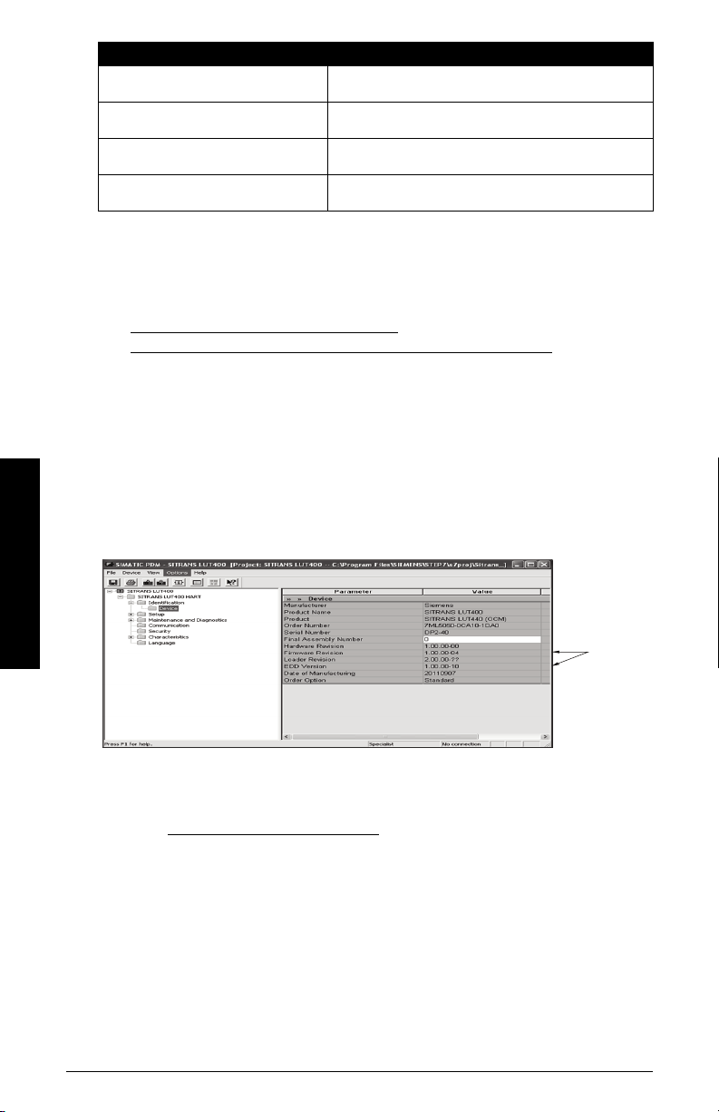
To check it in PDM, go to SITRANS LUT400 HART > Identification > Device.
TVT Shaper 29 Manual TVT adjustment
Auto False Echo Suppression 30 Screen out false echoes
Maintenance 32 Set schedules for device/sensor maintenance
Process Variables 36 Monitor process variables and level trend
SIMATIC PDM version
Check the support page of our website to make sure you have the latest version of SIMATIC
PDM, the most recent Service Pack (SP) and the most recent hot fix (HF). Go to:
http://support.automation.siemens.com/WW/
llisapi.dll?func=cslib.csinfo&lang=en&objiD=10806857&subtype=133100
Electronic Device Description (EDD)
You can locate the EDD in Device Catalog, under Sensors/Level/Echo/Siemens AG/
SITRANS LUT400. (The EDD is written for forward compatibility.)
As a guideline to locate the correct EDD, the major and minor numbers should match
between the EDD revision and the Firmware revision in the device (e.g. major and minor
numbers in bold text: 1.0 0 .00-04).
Operation - PDM
Installing a new version of SIMATIC PDM requires the most recent Service Pack (SP) and
the most recent hot fix (HF).
To install a new EDD
• Go to www.siemens.com/sitransLUT400 > Support > Software Downloads to
download the most up-to-date EDD from the product page of our website.
• Save the files to your computer and extract the zipped file to an easily accessed
Page 6 COMMUNICATIONS FOR SITRANS LUT400 (HART) – MANUAL A5E33701270
location.
• Launch SIMATIC PDM – Manage Device Catalog, browse to and select the folder
which contains the unzipped EDD file.

Configuring a new device
Notes:
• The first time the device is configured, you will be prompted to select a language
(English, German, French, Spanish, Chinese, Italian, Portuguese, or Russian). To
change the language again, use Language parameter [see
(LUI)
in LUT400 operating instructionsa].
• Clicking on Cancel during an upload from device to SIMATIC PDM will result in some
parameters being updated.
• Application Guides for setting up HART devices with SIMATIC PDM can be
downloaded from the product page of our website at:
www.siemens.com/sitransLUT400
a.
SITRANS LUT400 (HART) Operating Instructions (7ML19985MV01)
.
Parameter reference
1) Check that you have the most recent EDD, and if necessary update it (see
new EDD
2) Configure the device using the Quick Start Wizard. See
SIMATIC PDM
Before initiating a Quick Start Wizard to configure the device, you may wish to gather the
necessary parameter values. Parameter Configuration Charts listing all parameters and
available options for each application type are available on our website. Go to:
www.siemens.com/sitransLUT400
and select from options on the chart that apply to your application, then complete the
Quick Start Wizard via SIMATIC PDM
above).
Quick Start Wizard via
on page 7.
> Support > Application Guides. You can record data
on page 7.
Quick Start Wizard via SIMATIC PDM
Note: The layout of the dialog boxes shown may vary according to the resolution
setting for your computer monitor.
The graphic Quick Start Wizard provides an easy step-by-step guide to help you
configure the device for a simple application.
Please consult the operating instructions or online help for details on using SIMATIC
PDM. (Application Guides for setting up Siemens HART instruments with SIMATIC PDM
are available on our website: www.siemens.com/processautomation
1. If you have not already done so, check that you have the most up-to-date Electronic
Device Description (EDD) for your instrument. (See
page 7.)
2. Launch SIMATIC Manager and create a new project for LUT400. (Application Guides
for setting up HART devices with SIMATIC PDM can be downloaded from the
product page of our website at www.siemens.com/sitransLUT400
Configuring a new device
.)
.)
To install a
Operation - PDM
on
A5E33701270 COMMUNICATIONS FOR SITRANS LUT400 (HART) – MANUAL Page 7
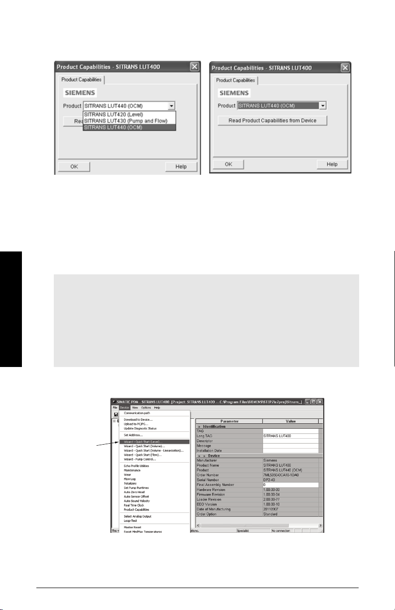
3. After opening object in SIMATIC PDM, set the product capabilities when prompted.
Quick
Starts
If you do not know the model connected, click on Read Product Capabilities from
Device, and the model will be automatically selected.
This setting decides what parameters are visible from the PDM menus.
4. Open the menu Device – Master Reset and click on OK to perform a reset to Factory
Defaults.
5. After the reset is complete upload parameters to the PC/PG.
6. Configure the device via the Quick Start Wizard for your application.
Quick Start Wizard steps
Notes:
• The Quick Start wizard settings are inter-related and changes apply only after you
click on Apply and Transfer at the end of the final step.
• Initial Quick Start parameter values are not default values and do not necessarily
reflect the current device configuration.
Operation - PDM
• The format of date fields in PDM will reflect the user’s operating system
configuration.
• Click on BACK to return and revise setting or Cancel to exit the Quick Start.
Open the Device menu in SIMATIC PDM and select the Quick Start applicable to your
application:
Page 8 COMMUNICATIONS FOR SITRANS LUT400 (HART) – MANUAL A5E33701270
• Quick Start (Level) (see page 9)
• Quick Start (Volume) (see page 12)
• Quick Start (Volume - Linearization) (see page 15)
• Quick Start (Flow) (see page 19)
Follow steps within the wizard to configure your device.
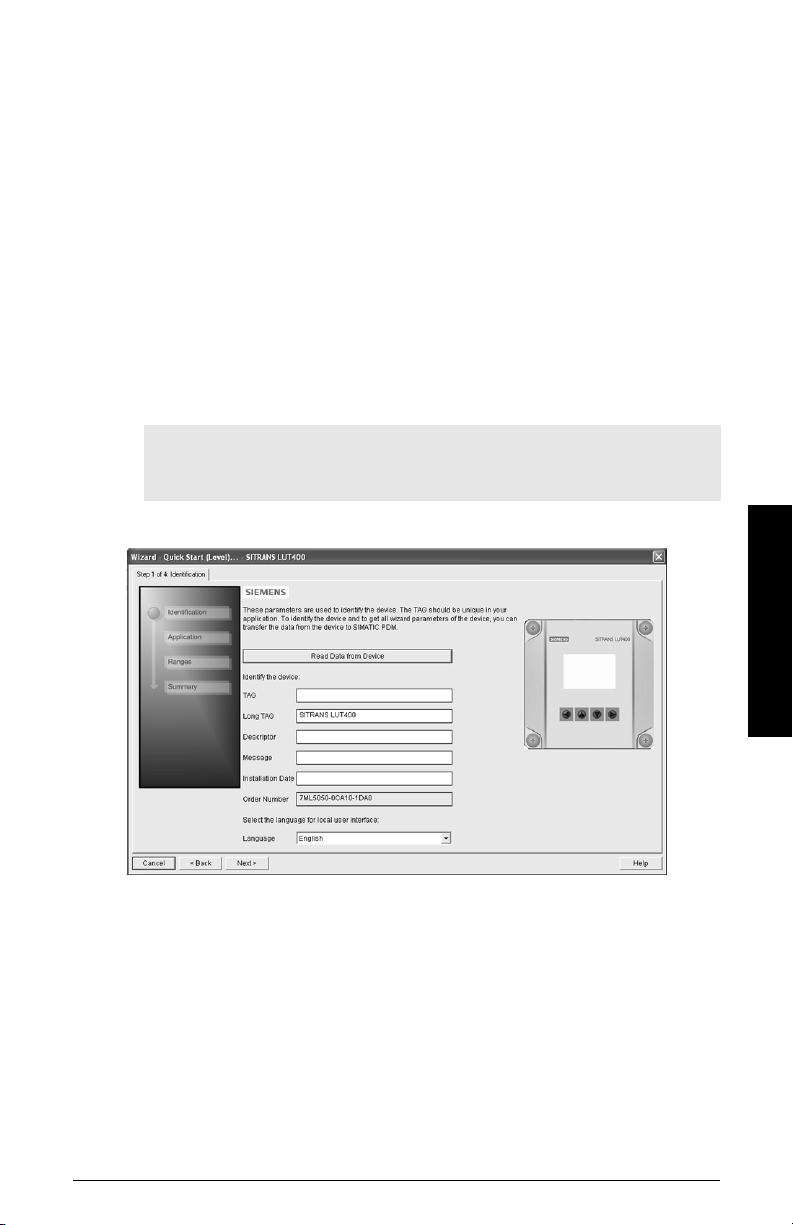
Quick Start (Level)
Step 1 – Identification
1. You can accept the default values without modification (TAG, Long TAG, Descriptor,
Message, and Installation Date fields can be left blank),
OR
1. Click on Read Data from Device (if this is not the first time running the Quick Start
Wizard).
2. The default Language is English. Select a different language value from the dropdown box if you wish to change the language displayed on the device.
Note: Italian, Portuguese and Russian are not supported in SIMATIC PDM for
SITRANS LUT400. If the device is set to one of these languages, it may be
necessary to switch the device to English, German, French, Spanish or Chinese.
Operation - PDM
3. After making all desired changes, click on Next.
Step 2 – Application
1. Select the Transducer that will operate with the LUT400.
2. Select the Application Type (Level, Space, Distance).
A5E33701270 COMMUNICATIONS FOR SITRANS LUT400 (HART) – MANUAL Page 9
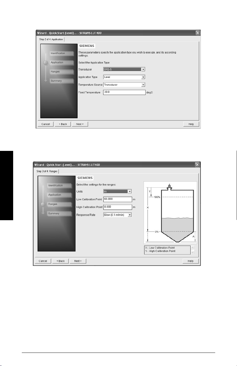
3. Select the Temperature Source (Transducer, Fixed Temperature, External TS-3,
Average of Transducer and TS-3), and if Fixed, enter the Fixed Temperature value.
4. Click on Next.
Step 3 - Ranges
1. Modify parameters as required.
Operation - PDM
2. Click on Next.
Step 4 – Summary
1. Check parameter settings, and click on Cancel to abort, or apply your changes.
Page 10 COMMUNICATIONS FOR SITRANS LUT400 (HART) – MANUAL A5E33701270
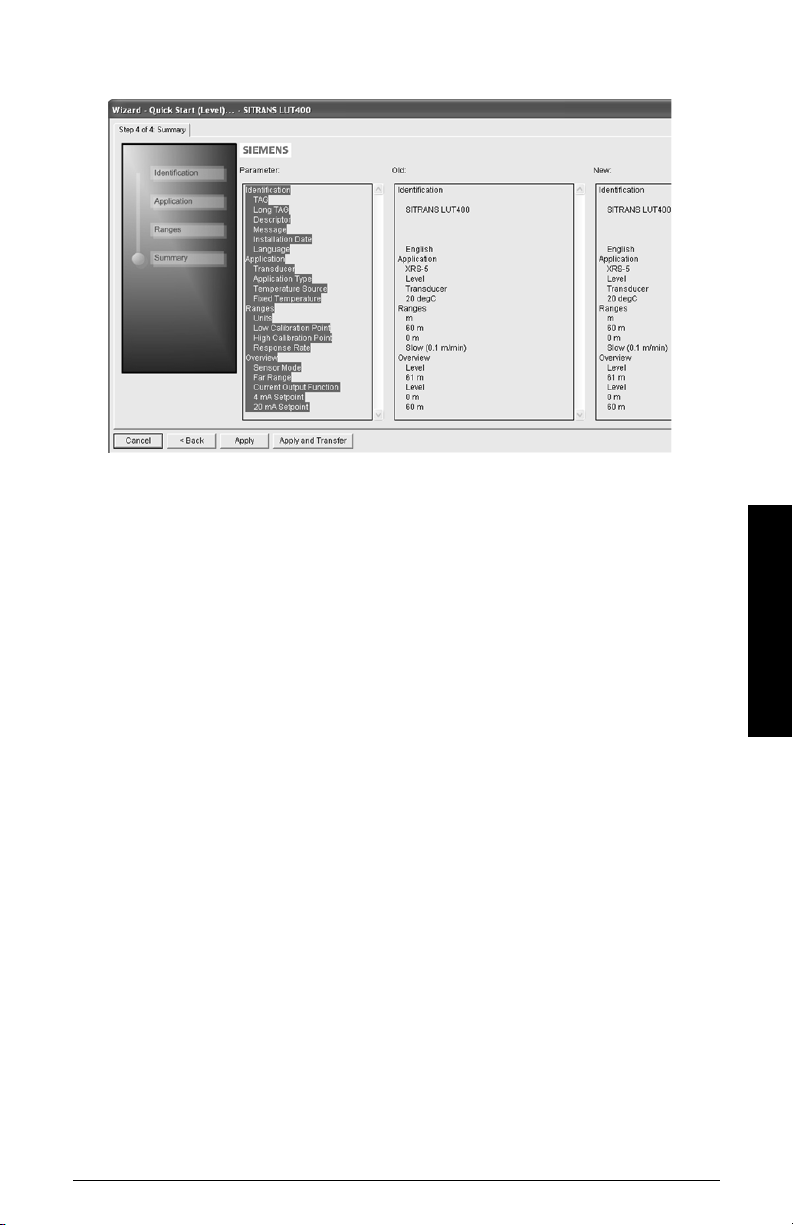
2. Click Apply to save your changes and return to the main menu, or click Apply and
Trans fer to save your changes and transfer settings to the device.
The message Quick Setup was successful will appear. Click on OK.
Configuration via the SIMATIC PDM Quick Start Wizard for a Level application is now
complete.
Operation - PDM
A5E33701270 COMMUNICATIONS FOR SITRANS LUT400 (HART) – MANUAL Page 11
Quick Start (Volume)
Use this wizard to configure volume applications employing standard vessel shapes.
Open the menu Device – Wizard - Quick Start (Volume):
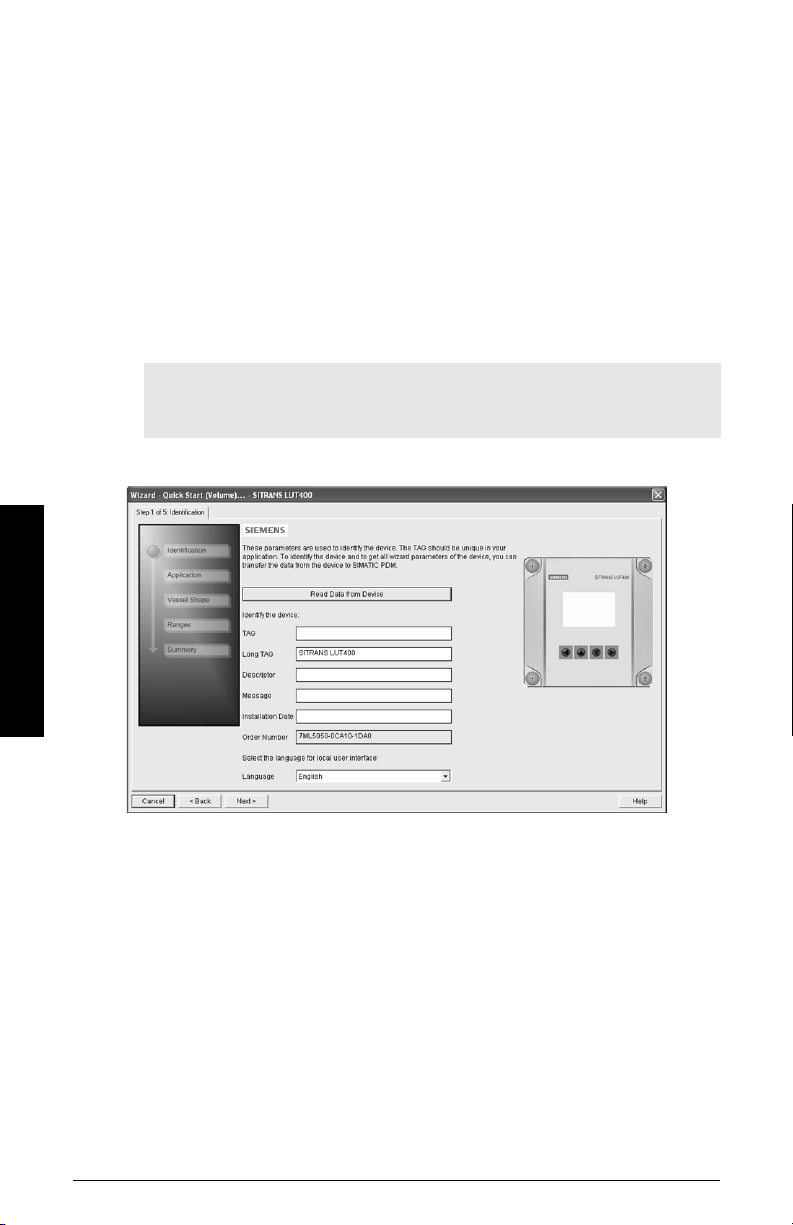
Step 1 – Identification
1. You can accept the default values without modification (TAG, Long TAG, Descriptor,
Message, and Installation Date fields can be left blank),
OR
1. Click on Read Data from Device (if this is not the first time running the Quick Start
Wizard).
2. The default Language is English. Select a different language value from the dropdown box if you wish to change the language displayed on the device.
Note: Italian, Portuguese and Russian are not supported in SIMATIC PDM for
SITRANS LUT400. If the device is set to one of these languages, it may be
necessary to switch the device to English, German, French, Spanish or Chinese.
Operation - PDM
3. After making all desired changes, click on Next.
Step 2 – Application
1. Select the Transducer that will operate with the LUT400.
The Application Type defaults to Volume.
Page 12 COMMUNICATIONS FOR SITRANS LUT400 (HART) – MANUAL A5E33701270
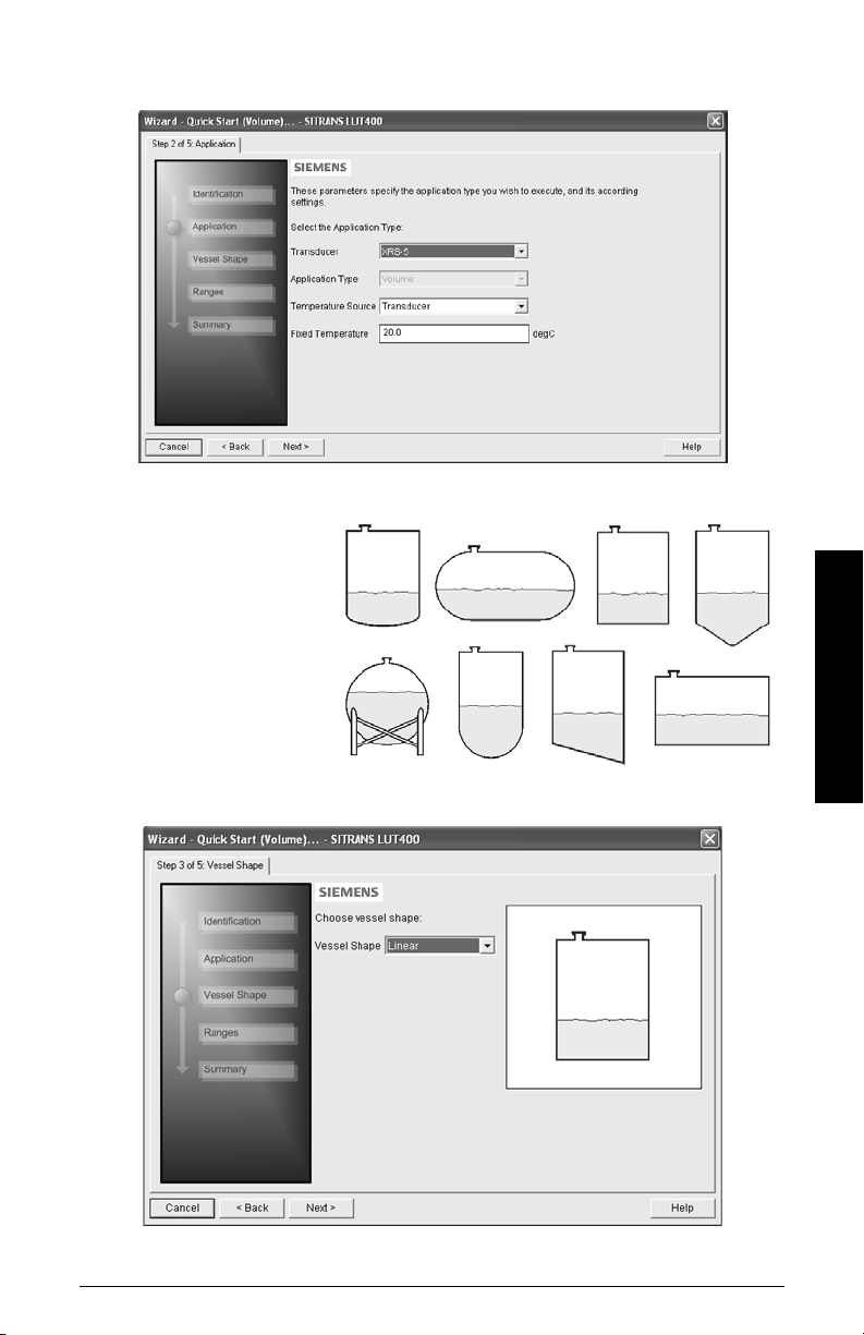
2. Select the Temperature Source (Transducer, Fixed Temperature, External TS-3,
Average of Transducer and TS-3), and if Fixed, enter the Fixed Temperature value.
3. Click on Next.
Step 3 - Vessel Shape
The vessel shapes shown
are predefined.
To describe a more
complex shape see
Quick
Start (Volume Linearization)
on page 15.
Operation - PDM
1. Select a Vessel
Shape for your Volume application.
2. Click on Next.
A5E33701270 COMMUNICATIONS FOR SITRANS LUT400 (HART) – MANUAL Page 13
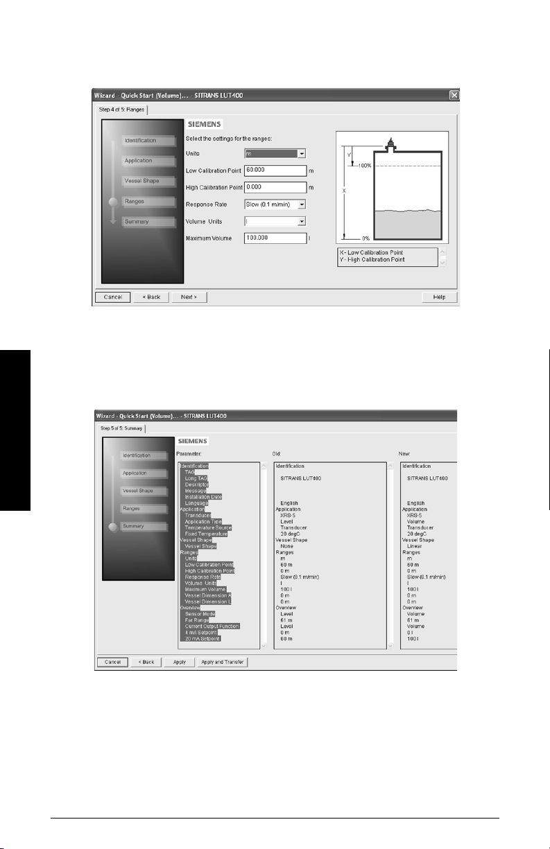
Step 4 - Ranges
1. Modify parameters as required. (Vessel Dimension A and L are required for certain
Vessel Shapes selected in previous step.)
2. Click on Next.
Step 5 – Summary
1. Check parameter settings, and click on Cancel to abort, or apply your changes.
2. Click Apply to save your changes and return to the main menu, or click Apply and
Trans fer to save your changes and transfer settings to the device.
Operation - PDM
The message Quick Setup was successful will appear. Click on OK.
Configuration via SIMATIC PDM Quick Start Wizard for a simple Volume application is
now complete.
Page 14 COMMUNICATIONS FOR SITRANS LUT400 (HART) – MANUAL A5E33701270
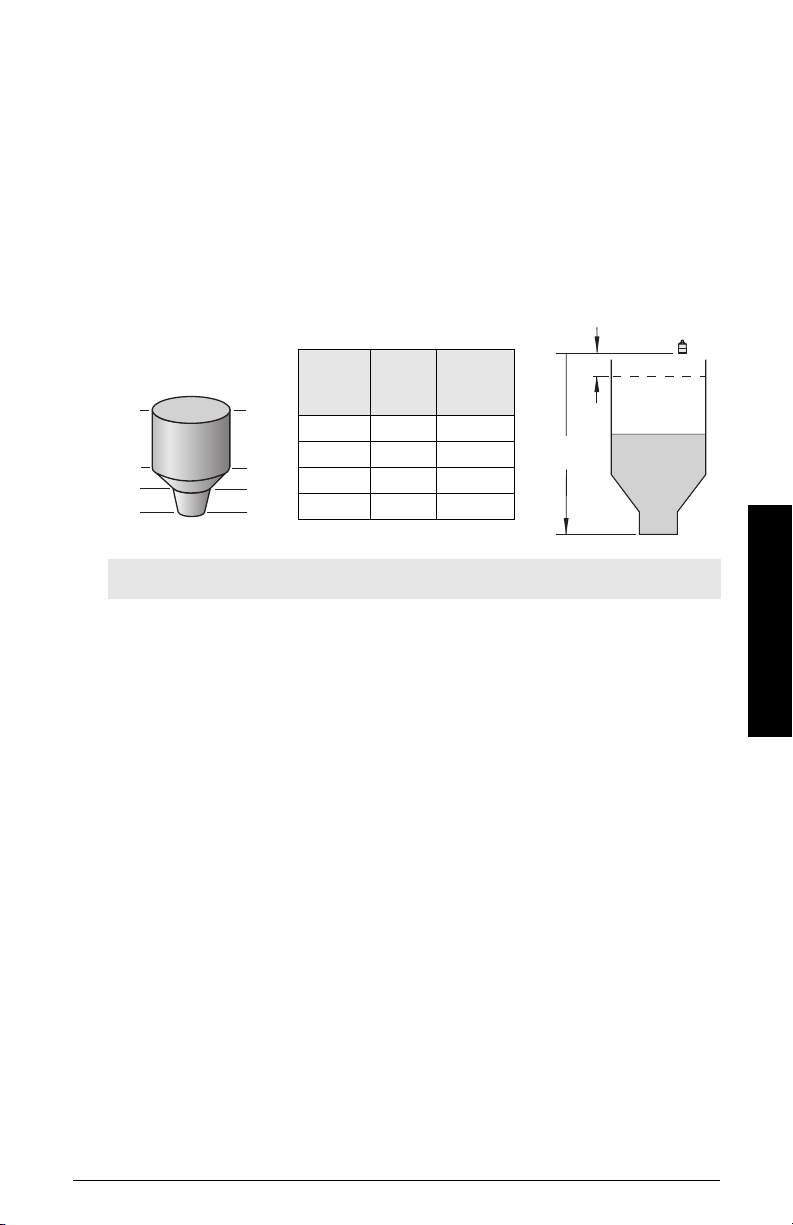
Quick Start (Volume - Linearization)
4
Breakpoint
number
3
2
1
Breakpoint no.
Level
value
(m)
Vol ume
value
(l)
1 (0%) 0 0
25500
3 9 3000
4 (100%) 19.5 8000
Level
value
9
5
0
20 m
0.5 m
19.5
Use this wizard to configure volume applications employing more complex vessel shapes.
Using Linearization via the Quick Start wizard
You can use the linearization feature to define a more complex vessel shape and enter up
to 32 level breakpoints where the corresponding volume is known. The values
corresponding to 0% and 100% levels must be entered. Breakpoints can be ordered from
top to bottom or the reverse, but should be entered in the wizard from the bottom to the
top of the vessel so that the characterization chart accurately reflects values as they are
entered.
Example:
Note: values are for example purposes only.
Open the menu Device – Wizard - Quick Start (Volume - Linearization):
Operation - PDM
Step 1 – Identification
1. You can accept the default values without modification (TAG, Long TAG, Descriptor,
Message, and Installation Date fields can be left blank),
OR
1. Click on Read Data from Device (if this is not the first time running the Quick Start
Wizard).
A5E33701270 COMMUNICATIONS FOR SITRANS LUT400 (HART) – MANUAL Page 15
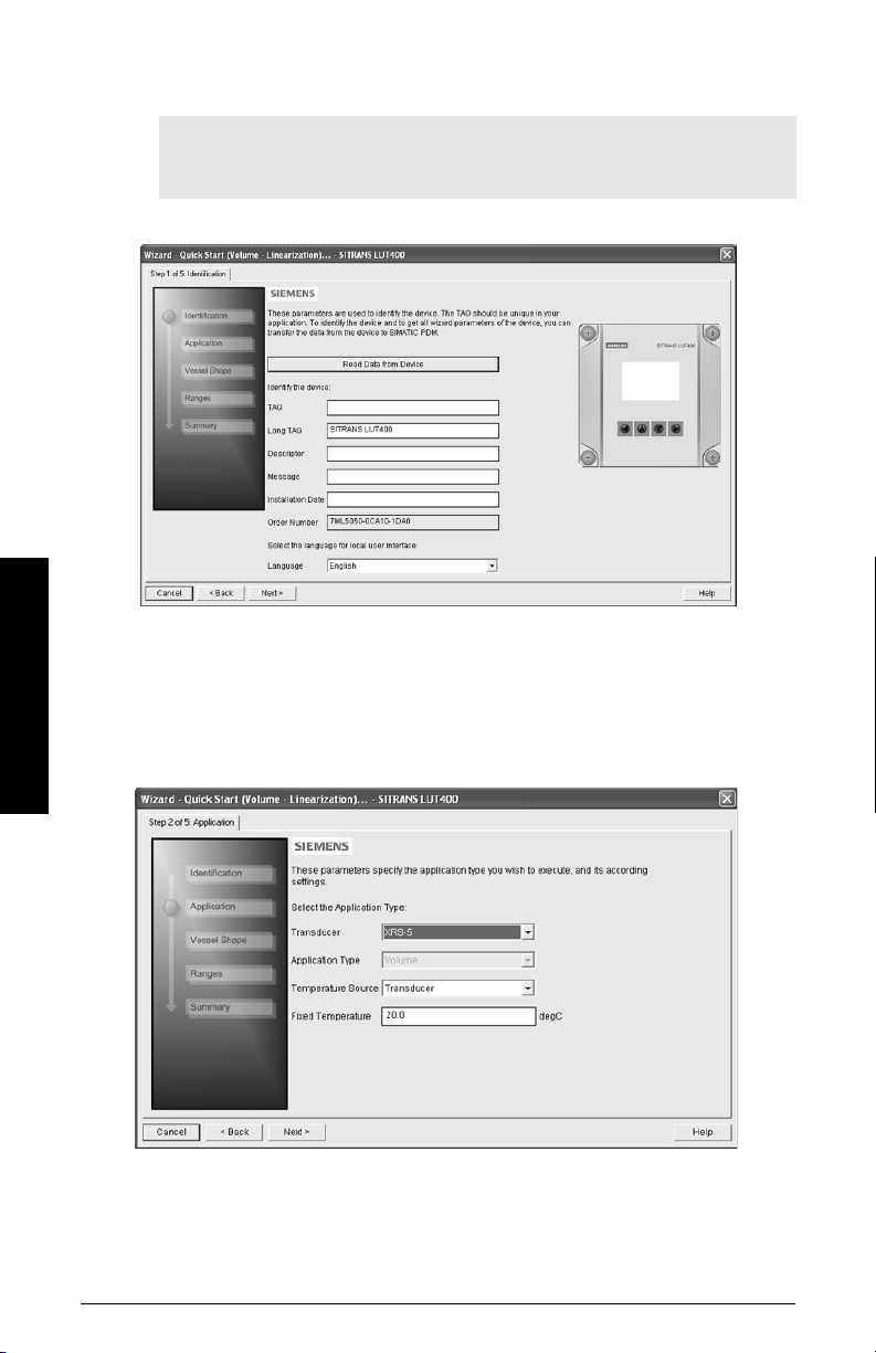
2. The default Language is English. Select a different language value from the drop-
3. After making all desired changes, click on Next.
Step 2 – Application
1. Select the Transducer that will operate with the LUT400.
Operation - PDM
2. Select the Temperature Source (Transducer, Fixed Temperature, External TS-3,
down box if you wish to change the language displayed on the device.
Note: Italian, Portuguese and Russian are not supported in SIMATIC PDM for
SITRANS LUT400. If the device is set to one of these languages, it may be
necessary to switch the device to English, German, French, Spanish or Chinese.
The Application Type defaults to Volume.
Average of Transducer and TS-3), and if Fixed, enter the Fixed Temperature value.
3. Click on Next.
Page 16 COMMUNICATIONS FOR SITRANS LUT400 (HART) – MANUAL A5E33701270

Step 3 – Vessel Shape
1. In this step, there are two options: Linearization Table and Curve Table. Breakpoints
will be entered in the same manner regardless of the table type selected, however a
different algorithm is used for Curve Table, to smooth the lines between breakpoints.
For example, use Curve Table when vessel sides are more rounded rather than
straight angles. Make a selection and click on NEXT.
Step 4 - Ranges
1. Modify parameters as required.
Operation - PDM
2. Click on Linearization to set breakpoints.
3. In the Linearization window click on the appropriate Breakpoint tab to open the
dialog window.
A5E33701270 COMMUNICATIONS FOR SITRANS LUT400 (HART) – MANUAL Page 17
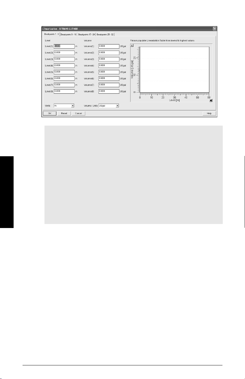
Operation - PDM
a. Enter the desired Level and Volume values, and click on OK.
Notes:
• The Reset button resets values to the values in the offline table.
• When entering breakpoints via the wizard, values should be entered from the
bottom to the top of the vessel so that the characterization chart accurately
reflects values as they are entered.
• To add points for Level and Volume equal to 0, enter these points first.
• When using a linear table, add at least two points.
• When using a curve table, add at least four points.
• If entering or modifying breakpoints via the parameter menu (after initial wizard
is complete), ensure
level/volume values being transferred, otherwise two uploads must be
performed:
a) one to read Linearization Table as enabled,
b) and one to transfer breakpoint values.
2.6.1.Vessel Shape
is set to Linearization Table prior to
c. Back in the Step 4 of 5: Ranges window, click on NEXT.
Step 5 - Summary
1. Check parameter settings, and click on Cancel to abort, or apply your changes.
2. Click Apply to save your changes and return to the main menu, or click Apply and
Trans fer to save your changes and transfer settings to the device.
The message Quick Setup was successful will appear. Click on OK.
Configuration via SIMATIC PDM Quick Start Wizard for a Volume application with a
complex vessel shape is now complete.
Page 18 COMMUNICATIONS FOR SITRANS LUT400 (HART) – MANUAL A5E33701270
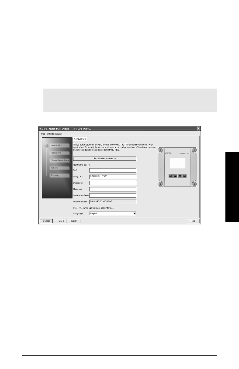
Quick Start (Flow)
Step 1 – Identification
1) You can accept the default values without modification (TAG, Long TAG, Descriptor,
Message, and Installation Date fields can be left blank),
OR
1) Click on Read Data from Device (if this is not the first time running the Quick Start
Wizard).
2. The default Language is English. Select a different language value from the dropdown box if you wish to change the language displayed on the device.
Note: Italian, Portuguese and Russian are not supported in SIMATIC PDM for
SITRANS LUT400. If the device is set to one of these languages, it may be
necessary to switch the device to English, German, French, Spanish or Chinese.
Operation - PDM
3) After making all desired changes, click on Next.
A5E33701270 COMMUNICATIONS FOR SITRANS LUT400 (HART) – MANUAL Page 19
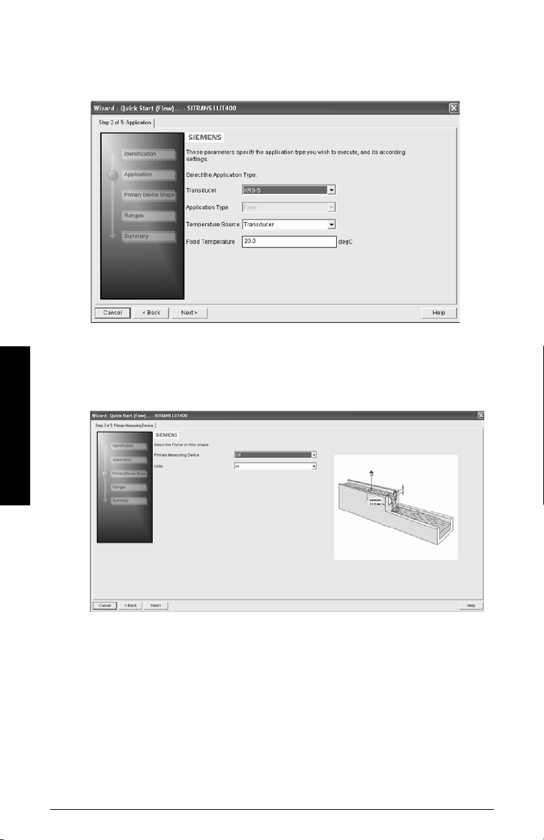
Step 2 – Application
1) Select the Transducer that will operate with the LUT400.
2) Select the Temperature Source (Transducer, Fixed Temperature, External TS-3,
Average of Transducer and TS-3), and if Fixed, enter the Fixed Temperature value.
3) Click on Next.
Step 3 – Primary Device Shape
1) Select a Primary Measuring Device for your Flow application and change Units if
desired.
Operation - PDM
2. Additional parameter default values appear depending on the Primary Measuring
Device selected. Modify as required.
3. Click on Next.
Page 20 COMMUNICATIONS FOR SITRANS LUT400 (HART) – MANUAL A5E33701270
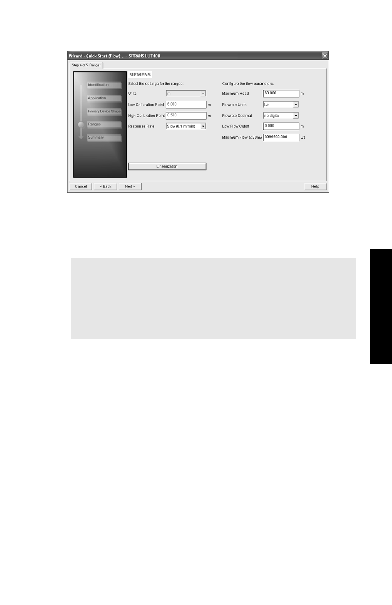
Step 4 - Ranges
1) Modify parameters as required.
2. If PMD selected in Step 3 was Universal Head Flow, the Linearization button will
appear in Step 4. Click on Linearization to set Head and Flow Breakpoints, then click
OK to return to the Step 4.
3. Click on Next.
Notes:
• If entering or modifying breakpoints via the parameter menu (after initial wizard
is complete), ensure
Head Flow prior to head/flow values being transferred, otherwise two uploads
must be performed:
a) one to read Universal Head Flow as enabled,
b) and one to transfer breakpoint values.
2.15.1.Primary Measuring Device (PMD)
is set to Universal
Step 5 – Summary
1. Check parameter settings, and click on Cancel to abort, or apply your changes.
2. Click Apply to save your changes and return to the main menu, or click Apply and
Trans fer to save your changes and transfer settings to the device.
The message Quick Setup was successful will appear. Click on OK.
Configuration via SIMATIC PDM Quick Start Wizard for a Flow application is now
complete.
Operation - PDM
A5E33701270 COMMUNICATIONS FOR SITRANS LUT400 (HART) – MANUAL Page 21
Pump Control Wizard
The Pump Control Setup Wizard provides an easy step-by-step guide to help you
configure the pumps and relays for a simple application.
Pump Control Wizard steps
Notes:
• Complete the appropriate Quick Start Wizard (Level, Volume, or Volume
Linearization) prior to programming pump control.
• The Pump Control Setup Wizard settings are inter-related and changes apply only
after you click on Apply and Transfer at the end of the final step.
• Initial Pump Control Wizard parameter values are not default values and do not
necessarily reflect the current device configuration.
• Click on BACK to return and revise setting or Cancel to exit the Pump Control Wizard.
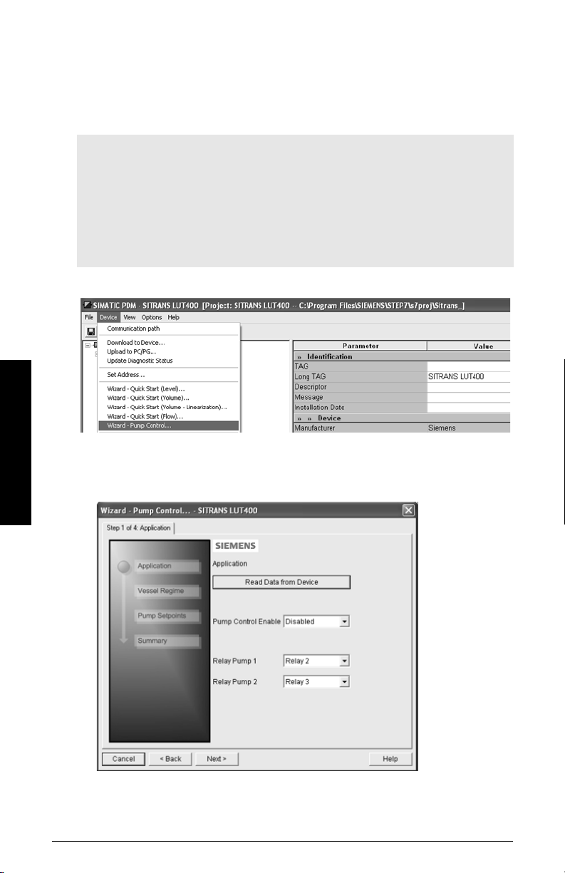
Launch SIMATIC PDM, open the menu Device – Wizard - Pump Control, and follow steps.
Step 1 – Application
Operation - PDM
1) Enable pump control, and select which relay is wired to Pump 1. (The relay for Pump
2 will be set automatically based on your selection for Pump 1.)
2. Click on Next.
Page 22 COMMUNICATIONS FOR SITRANS LUT400 (HART) – MANUAL A5E33701270
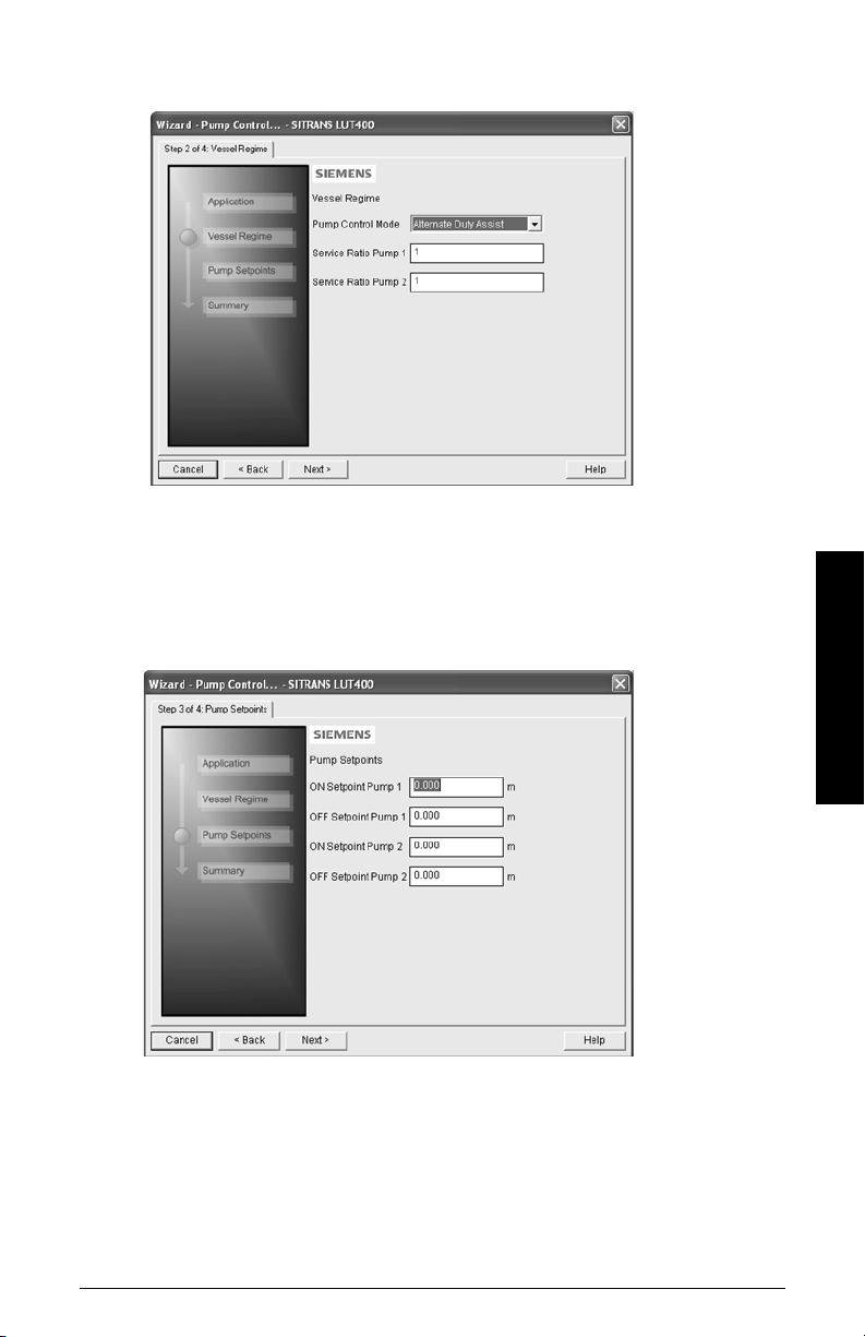
Step 2 – Vessel Regime
1) Select the Pump Control Mode.
2. If Service Ratio Duty Assist, or Service Ratio Duty Backup selected enter the Service
Ratio for each pump.
3. Click on Next.
Step 3 – Pump Setpoints
1) Enter the start level (ON Setpoint), and stop level (OFF Setpoint) for each pump, then
click on Next.
Operation - PDM
Step 4 – Summary
1. Check parameter settings, and click on Cancel to abort, or apply your changes.
A5E33701270 COMMUNICATIONS FOR SITRANS LUT400 (HART) – MANUAL Page 23
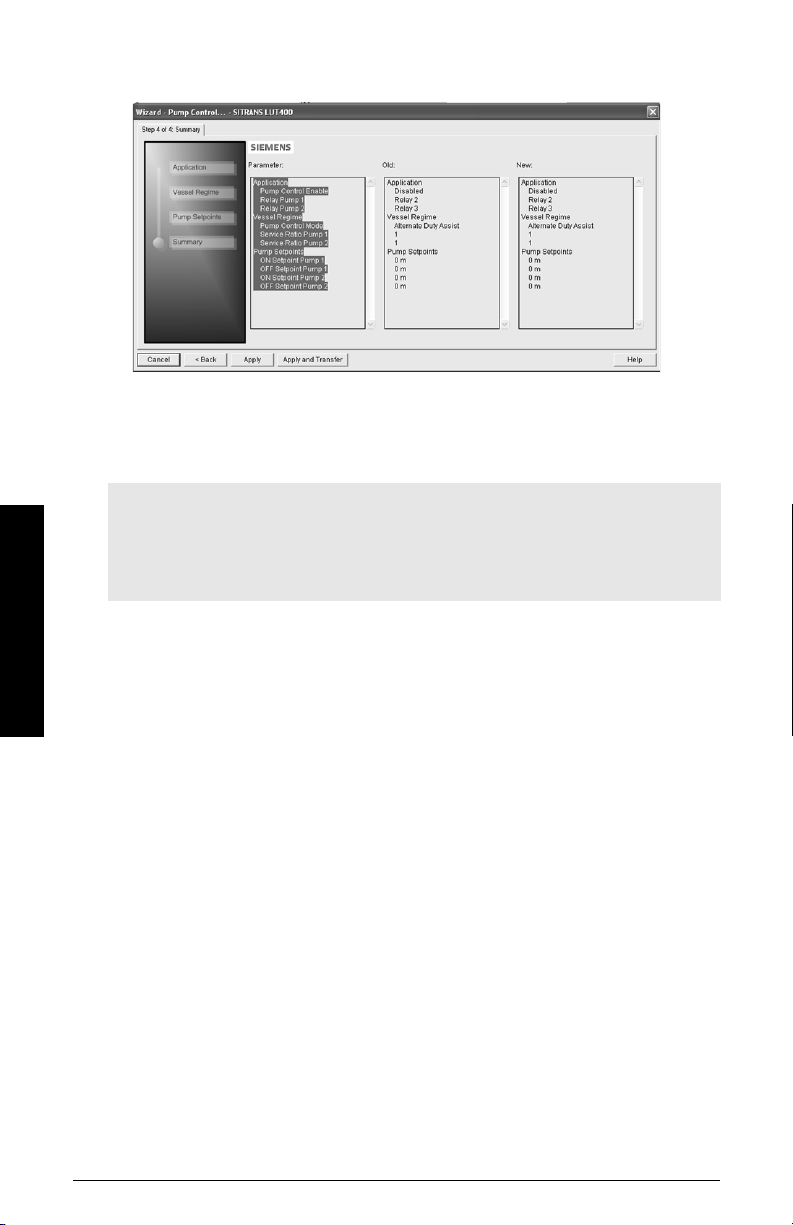
2. Click Apply to save your changes and return to the main menu, or click Apply and
Trans fer to save your changes and transfer settings to the device.
Pump configuration via PDM Pump Control Wizard is now complete.
Changing parameter settings using SIMATIC PDM
Notes:
• For a complete list of parameters, see
instructionsa.
• Clicking on Cancel during an upload from device to SIMATIC PDM will result in some
parameters being updated.
a.
SITRANS LUT400 (HART) Operating Instructions (7ML19985MV01)
Parameter reference (LUI)
in LUT400 operating
Operation - PDM
Many parameters are accessed via the 5-level menu in PDM. See
pull-down menus
1) Launch SIMATIC PDM, connect to SITRANS LUT400, and upload data from the
device.
2) Adjust parameter values in the parameter value field and then press Enter. The
status fields read Changed.
Page 24 COMMUNICATIONS FOR SITRANS LUT400 (HART) – MANUAL A5E33701270
below for the others.
Parameters accessed via
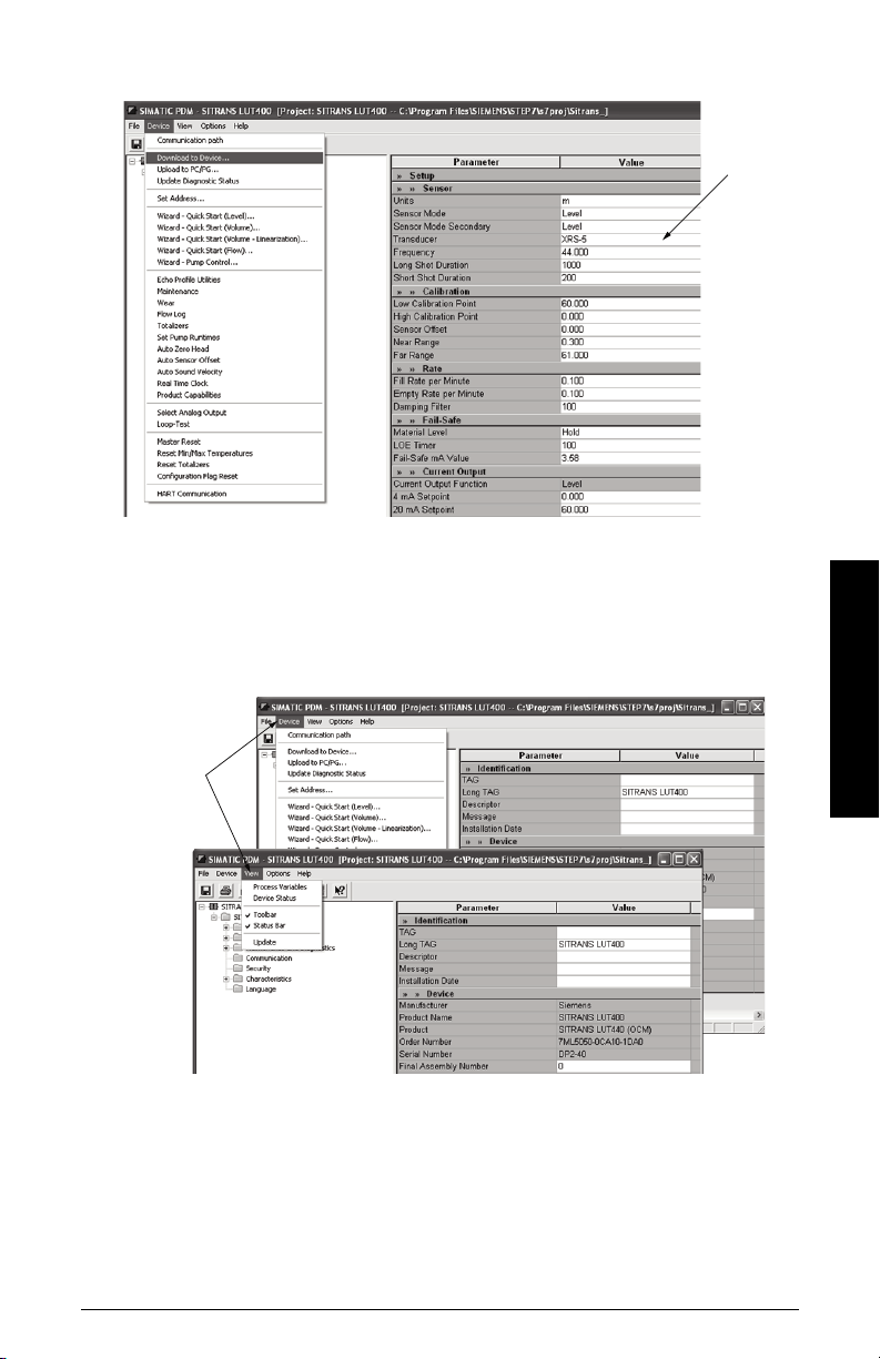
3) Open the Device menu, click on Download to device, then use File – Save, to save
value
fields
pull-down
menus
parameter settings. The status fields are cleared.
Parameters accessed via pull-down menus
You have access to a number of functions via pull-down menus from the menu bar under
Device or View.
For a complete list, see pull-down menus below.
Operation - PDM
A5E33701270 COMMUNICATIONS FOR SITRANS LUT400 (HART) – MANUAL Page 25

Pull-down menus
Operation - PDM
Device menus page View menus page
Communication path -
Download to Device
Upload to PC/PG
Update Diagnostic Status
Set Address 27
Wizard - Quick Start (Level)
Wizard - Quick Start (Volume)
Wizard - Quick Start (Volume - Linearization)
Wizard - Quick Start (Flow) *
Wizard - Pump Control
Echo Profile Utilities
Maintenance
Wear
Flow Log *
Tot a l i z ers *
Set Pumps Runtimes *
Auto Zero Head *
Auto Sensor Offset
Auto Sound Velocity
Real Time Clock
Product Capabilities
Select Analog Output
Loop-Test
Master Reset
Reset Min/Max Temperatures
Reset Totalizers *
Configuration Flag Reset
HART Communication 36
Process Variables
Device Status
-
-
-
9
12
15
19
22
27
32
33
33
33
33
34
34
34
34
34
35
35
35
36
36
36
To ol b a r
Status Bar
Update -
36
39
-
-
* Selected menus visible only if Product Capabilities set to Pump and Flow or OCM.
Page 26 COMMUNICATIONS FOR SITRANS LUT400 (HART) – MANUAL A5E33701270
 Loading...