

Siemens SITRANS LR560 Operating Instructions Manual

Radar Transmitters
SITRANS LR560 (mA/HART)
Operating Instructions
03/2016Edition

Safety Guidelines: Warning notices must be observed to ensure personal safety as well as that of
others, and to protect the product and the connected equipment. These warning notices are
accompanied by a clarification of the level of caution to be observed.
Qualified Personnel: This device/system may only be set up and operated in conjunction with this
manual. Qualified personnel are only authorized to install and operate this equipment in accordance with
established safety practices and standards.
Unit Repair and Excluded Liability:
• The user is responsible for all changes and repairs made to the device by the user or the user’s
agen
t.
• All new components are to be provided by Siemens.
• Restrict repair to faulty components only.
• Do not reuse faulty components.
Warning: Cardboard shipping package provides limited humidity and moisture protection. This product
can only function properly and safely if it is correctly transported, stored, installed, set up, operated, and
maintained.
This product is intended for use in industrial areas. Operation of this equipment in a residential area
may cause interference to several frequency based communications.
Note: Always use product in accordance with specifications.
Copyright Siemens AG 2016. All Rights
Disclaimer of Liability
Reserved
This document is available in bound version and in
electronic version. We encourage users to purchase
authorized bound manuals, or to view electronic
versions as designed and authored by Siemens.
Siemens will not be responsible for the contents of
partial or whole reproductions of either bound or
electronic versions.
u
ropean Authorized Representative
E
Siemens AG
Industry Sector
76181 Karlsruhe
Deutschland
• For a selection of Siemens level measurement manuals, go
www. siemens.com/processautomation. Select Products & Systems, then under Process
Instrumentation, select
product family.
• For a selection of Siemens weighing manuals, go to:
www. siemens.com/processautomation. Under Products & Systems, select
Batching Systems.
Level Measurement.
Manual archives can be found on the Support page by product family.
While we have verified the contents of this
manual for agreement with the
instrumentation described, variations remain
possible. Thus we cannot guarantee full
agreement. The contents of this manual are
regularly reviewed and corrections are
included in subsequent editions. We welcome
all suggestions for improvement.
Technical data subject to change.
to:
Manual archives can be found on the Support page by
Weighing and
iemens AG 2016
© S

Table of Contents
Introduction ........................................................................................................................1
The Manual ............................................................................................................................................1
Application Example ...................................................................................................................1
Technical Support .......................................................................................................................1
Abbreviations and Identifications ...........................................................................................2
Safety Notes .......................................................................................................................3
Safety marking symbols ......................................................................................................................3
Industry Canada ....................................................................................................................................3
FCC Conformity ......................................................................................................................................4
CE Electromagnetic Compatibility (EMC) Conformity ...................................................................4
R&TTE Compliance (Europe) ..............................................................................................................5
SITRANS LR560 Overview ................................................................................................7
Programming .........................................................................................................................................7
Local Display Interface (LDI) ..............................................................................................................8
Versions ..................................................................................................................................................8
Applications ............................................................................................................................................8
Approvals and Certificates .................................................................................................................8
Specifications ....................................................................................................................9
Power............................................................................................................................................. 9
Performance................................................................................................................................. 9
Interface...................................................................................................................................... 10
Mechanical................................................................................................................................. 10
Environmental............................................................................................................................ 11
Process........................................................................................................................................ 11
Approvals.................................................................................................................................... 12
Programmer (infrared keypad).............................................................................................. 12
Dimensions ...........................................................................................................................................13
Universal flat-faced flange .....................................................................................................18
Universal stamped flange .......................................................................................................19
Installation ........................................................................................................................21
Mounting location ...............................................................................................................................22
Nozzle location ..........................................................................................................................22
Aimer Adjustment .....................................................................................................................24
Air Purging System .............................................................................................................................25
Purge Connection .....................................................................................................................25
Wiring ................................................................................................................................27
Power .....................................................................................................................................................27
Connecting SITRANS LR560 .............................................................................................................27
Connecting HART ......................................................................................................................28
Wiring setups for hazardous area installations ................................................................29
Non-incendive and Dust Ignition Proof wiring (US/Canada) .........................................29
Instructions specific to hazardous area installations ......................................................30
Local operation ................................................................................................................31
Activating SITRANS LR560 ...............................................................................................................31
Table of Contents
i

The LCD Display ........................................................................................................................32
Handheld Programmer ...........................................................................................................33
Programming SITRANS LR560 ...............................................................................................34
Quick Start Wizard via the LDI push buttons ...............................................................................37
Quick Start Wizard via the handheld programmer .....................................................................37
Requesting an Echo Profile ..............................................................................................................40
Level application example ................................................................................................................42
Operating via SIMATIC PDM .........................................................................................43
Table of C on t en ts
Functions in SIMATIC PDM ..............................................................................................................43
SIMATIC PDM Version ......................................................................................................................43
Electronic Device Description (EDD) ....................................................................................43
Configuring a new device .......................................................................................................44
Quick Start Wizard via SIMATIC PDM ..........................................................................................44
Changing parameter settings using SIMATIC PDM ...................................................................47
Parameters accessed via pull-down menus ......................................................................48
Security ........................................................................................................................................58
Operating via FDT (Field Device Tool) .........................................................................59
Device Type Manager (DTM) ..........................................................................................................59
SITRANS DTM .....................................................................................................................................59
The Instrument EDD ...........................................................................................................................59
Configuring a new device via FDT ..................................................................................................59
Operating via AMS Device Manager ...........................................................................61
Functions in AMS Device Manager ...............................................................................................61
Features of AMS Device Manager .......................................................................................61
Device Description (DD) ..........................................................................................................61
Configuring a new device .......................................................................................................62
Startup .........................................................................................................................................62
Pull-down menu access ..........................................................................................................63
Device configuration ................................................................................................................63
Quick Start Wizard via AMS Device Manager ..................................................................64
Maintenance and Diagnostics ........................................................................................................71
Communication ....................................................................................................................................73
Security .................................................................................................................................................73
Device Diagnostics .............................................................................................................................74
Password Protection ................................................................................................................75
User Manager Utility ................................................................................................................75
AMS Menu Structure .......................................................................................................................76
Parameter Reference .....................................................................................................83
Quick Start .................................................................................................................................. 83
Quick Start Wizard.......................................................................................................... 83
AFES (Auto False Echo Suppression) Wizard.......................................................... 84
Copy Parameters to Display......................................................................................... 85
Copy Parameters from Display.................................................................................... 85
Copy Firmware to Display............................................................................................. 85
Copy Firmware from Display........................................................................................ 86
Setup............................................................................................................................................ 86
Device ................................................................................................................................ 86
Sensor ............................................................................................................................... 87
Calibration......................................................................................................................... 88
ii

Rate..................................................................................................................................... 89
Fail-safe............................................................................................................................. 91
Analog Output Scaling................................................................................................... 92
Signal Processing............................................................................................................ 95
TVT setup........................................................................................................................ 100
TVT shaper..................................................................................................................... 101
Measured Values......................................................................................................... 102
Diagnostics.............................................................................................................................. 103
Fault Reset ..................................................................................................................... 103
Echo Profile.................................................................................................................... 103
Trend ............................................................................................................................... 104
Peak Values................................................................................................................... 104
Electronics Temperature............................................................................................ 104
Remaining Device Lifetime ........................................................................................ 105
Remaining Sensor Lifetime........................................................................................ 107
Service...................................................................................................................................... 110
Demo Mode................................................................................................................... 110
Master Reset................................................................................................................. 110
Powered Hours............................................................................................................. 110
Power-on Resets.......................................................................................................... 110
LCD Backlight................................................................................................................ 110
LCD Contrast.................................................................................................................. 111
Service Schedule ......................................................................................................... 111
Calibration Schedule................................................................................................... 114
Stored Software Version............................................................................................ 116
Communication....................................................................................................................... 116
Device Address............................................................................................................. 116
Remote Lockout............................................................................................................ 117
Security..................................................................................................................................... 117
Write Protection ........................................................................................................... 117
Language.................................................................................................................................. 117
Appendix A: Alphabetical Parameter List ................................................................119
Appendix B: Troubleshooting .....................................................................................123
Communication Troubleshooting ..................................................................................................123
Device Status Icons .........................................................................................................................124
General Fault Codes .........................................................................................................................125
Operation Troubleshooting ............................................................................................................128
Appendix C: Maintenance ...........................................................................................131
Unit Repair and Excluded Liability ................................................................................................131
Appendix D: Technical Reference .............................................................................133
Principles of Operation ....................................................................................................................133
Process Variables ...................................................................................................................133
Echo Processing ...............................................................................................................................134
Process Intelligence ...............................................................................................................134
Echo Selection .........................................................................................................................134
Measurement Range .............................................................................................................138
Measurement Response .......................................................................................................139
Analog Output ....................................................................................................................................139
Sensor Mode (2.2.2.) ...............................................................................................................140
Table of Contents
iii

Current Output Function (2.6.1.) ...........................................................................................140
Loss of Echo (LOE) ..................................................................................................................141
Temperature derating curve .........................................................................................................142
Loop power .........................................................................................................................................143
Typical Connection Drawing ................................................................................................143
Allowable operating area of SITRANS LR560 ..................................................................144
Startup Behavior .....................................................................................................................144
Appendix E: HART Communications .........................................................................145
Table of C on t en ts
SIMATIC PDM ...................................................................................................................................145
HART Electronic Device Description (EDD) ................................................................................145
HART Communicator 375 Menu Structure ................................................................................146
HART Version .....................................................................................................................................150
Burst Mode ...............................................................................................................................150
HART Multidrop Mode ...........................................................................................................150
Appendix F: Firmware Revision History ....................................................................151
Glossary ..........................................................................................................................153
Index ................................................................................................................................157
LCD menu structure ......................................................................................................161
iv

Introduction
The Manual
Notes:
• This product is intended for use in industrial areas. Operation of this equipment in a
residential area may cause interference to several frequency based
communications.
• Please follow the installation and operating procedures for a quick, trouble-free
installation and to ensure the maximum accuracy and reliability of your SITRANS LR560.
• This manual applies to the SITRANS LR560 (mA/HART) only.
For other Siemens level measurement manuals, go to:
www.siemens.com/level and look under Level Measurement.
Application Example
The application example used in this manual illustrates a typical installation using
SITRANS LR560. (See
range of ways to approach an application, other configurations may also apply.
In all examples, substitute your own application details. If the example does not apply to
your application, check the applicable parameter reference for the available options.
Level application example
Technical Support
on page 42.) Because there is often a
SITRANS LR560
If you have any technical questions about the device described in these Operating
Instructions and do not find the right answers, you can contact Customer Support:
• Via the Internet using Support Request
• Via Phone:
• Europe: +49 (0)911 895 7222
• America: +1 423 262 5710
• Asia-Pacific: +86 10 6475 7575
Service and support on the Internet
In addition to our documentation, we offer a comprehensive knowledge base online at
Service and Support. There you will find:
• The latest product information, FAQs, downloads, tips and tricks.
• Our newsletter, providing you with the latest information about your products.
• Our bulletin board, where users and specialists share their knowledge worldwide.
• Your local contact partner for Industry Automation and Drives Technologies in our
partner database.
• Information about field service, repairs, spare parts and much more under
"Services."
A5E34647946 SITRANS LR560 (mA/HART) – OPERATING INSTRUCTIONS Page 1

Additional Support
Please contact your local Siemens representative and offices if you have additional
questions about the device.
Find your contact partner at Your personal contact.
Abbreviations and Identifications
Short
form
CE / FM /
CSA
DCS Distributed Control System control room apparatus
dK dielectric constant
EDD Electronic Device Description
SITRANS LR560
ESD Electrostatic Discharge
FMCW Frequency Modulated Continuous Wave radar principle
I
i
I
o
LCD Liquid Crystal Display
LDI Local Display Interface
LUI Local User Interface
μs microsecond 10
PA Process Automation (PROFIBUS)
PED Pressure Equipment Directive safety approval
ppm parts per million
PV Primary Value measured value
SELV Safety extra low voltage
SV Secondary Value equivalent value
TB Transducer Block
TVT Time Varying Threshold sensitivity threshold
U
i
U
o
Long Form Description Units
Conformité Européene / Factory Mutual /
Canadian Standards Association
Input current mA
Output current mA
Input voltage V
Output voltage V
safety approval
removable display with push
buttons
view outputs via LCD display;
make modifications via push
buttons or handheld programmer
-6
Second
Page 2 SITRANS LR560 (mA/HART) – OPERATING INSTRUCTIONS A5E34647946
Safety Notes
Special attention must be paid to warnings and notes highlighted from the rest of the text
by grey boxes.
WARNING symbol relates to a caution symbol on the product, and
means that failure to observe the necessary precautions can result
in death, serious injury, and/or considerable material damage.
WARNING symbol, used when there is no corresponding caution
symbol on the product, means that failure to observe the necessary
precautions can result in death, serious injury, and/or considerable
material damage.
means important information about the product or that part of the manual.
Note:
Safety marking symbols
In manual On product Description
Earth (ground) Terminal
Protective Conductor Terminal
(Label on product: yellow background.) WARNING: refer
to accompanying documents (manual) for details.
Industry Canada
The SITRANSLR560 complies with Industry Canada standard RSS211 (March 2015).
a. The installation of the SITRANS LR560 shall be done by trained installers, in
strict compliance with the manufacturer’s instructions.
b. The use of this device is on a "no-interference, no-protection" basis. That is,
the user shall accept operations of high-powered radar in the same
frequency band which may interfere with or damage this device. However,
devices found to interfere with primary licensing operations will be
required to be removed at the user's expense.
c. The installer/user of this device shall ensure that it is at least 10 km from
the Dominion Astrophysical Radio Observatory (DRAO) near Penticton,
British Columbia. The coordinates of the DRAO are latitude 49°19’15" N and
longitude 119°37’12" W. For devices not meeting this 10 km separation (e.g.,
those in the Okanagan Valley, British Columbia,) the installer/user must
coordinate with, and obtain the written concurrence of, the Director of the
DRAO before the equipment can be installed or operated. The Director of
the DRAO may be contacted at 250-497-2300 (tel.) or 250-497-2355 (fax).
(Alternatively, the Manager, Regulatory Standards, Industry Canada, may
be contacted.)
Safety Notes
A5E34647946 SITRANS LR560 (mA/HART) – OPERATING INSTRUCTIONS Page 3

FCC Conformity
US Installations only: Federal Communications Commission (FCC) rules
WARNING: Changes or modifications not expressly approved by
Siemens could void the user’s authority to operate the equipment.
Notes:
• This device has been tested and found to comply with the limits Class B digital
device part 15 of the FCC Rules. These limits are designed to provide reasonable
protection against harmful interference when the equipment is operated in a
commercial environment.
• This device has also been tested and found to comply with the limits §15.256,
Subpart C-Intentional radiators, pursuant to Part 15 of the FCC Rules. These limits
are designed to provide reasonable protection against harmful interference when
the equipment is operated in a commercial environment.
• This device generates, uses, and can radiate radio frequency energy and, if not
installed and used in accordance with the instruction manual, may cause harmful
interference to radio communications, in which case the user will be required to
correct the interference at his/her own expense.
• This device may be used to measure levels in fixed or mobile enclosed tanks.
• This device may be used to measure levels in open air environments or outside
enclosed tanks, subject to the following conditions:
o Devices shall be installed and maintained to ensure a vertically downward
orientation of the transmit antenna's main beam.
o Devices shall be installed only at fixed locations. Devices shall not operate
while being moved or while inside a moving container.
o Hand-held applications and residential use are prohibited.
Safety Notes
CE Electromagnetic Compatibility (EMC) Conformity
This equipment has been tested and found to comply with the following EMC Standards:
EMC Standard Title
CISPR 11:2004/EN
55011:1998+A1:1999&A2:2002
, CLASS B
EN
61326:1997+A1:1998+A2:2001
+A3:2003 (IEC 61326:2002)
EN61000-4-2:2001
EN61000-4-3:2002
EN61000-4-4:2004
EN61000-4-5:2001
EN61000-4-6:2004
Page 4 SITRANS LR560 (mA/HART) – OPERATING INSTRUCTIONS A5E34647946
Limits and methods of measurements of radio disturbance
characteristics of industrial, scientific, and medical (ISM) radiofrequency equipment.
Electrical Equipment for Measurement, Control and Laboratory Use
– Electromagnetic Compatibility.
Electromagnetic Compatibility (EMC) Part 4-2:Testing and
measurement techniques – Electrostatic discharge immunity test.
Electromagnetic Compatibility (EMC) Part 4-3: Testing and
measurement techniques – Radiated, radio-frequency,
electromagnetic field immunity test.
Electromagnetic Compatibility (EMC) Part 4-4: Testing and
measurement techniques – Electrical fast transient/burst immunity
test.
Electromagnetic Compatibility (EMC) Part 4-5: Testing and
measurement techniques – Surge immunity test.
Electromagnetic Compatibility (EMC) Part 4-6: Testing and
measurement techniques – Immunity to conducted disturbances,
induced by radio-frequency fields.

EMC Standard Title
Electromagnetic Compatibility (EMC) Part 4-8:
EN61000-4-8:2001
Testing and measurement techniques – Power frequency magnetic
field immunity test.
R&TTE Compliance (Europe)
Hereby, Siemens, declares that the SITRANS LR560 is in compliance with the essential
requirements and other relevant provisions of Directive 1999/5/EC.
The LR560 complies with EN 302 372 for use in closed storage vessels, when installed
according to the installation requirements of EN 302 372, and may be used in all EU
countries.
The LR560 complies with EN 302 729 for use outside of closed tanks in EU countries. For
open air installations, the following conditions must be observed:
Installation and maintenance is performed by suitably qualified and trained
personnel.
The LR560 shall be installed only in a permanent fixed position pointing downwards.
Its location shall comply with the following two restrictions:
1) It shall be installed with a minimum separation distance of 4 km from Radio
Astronomy sites listed at www.craf.eu/raobs.htm
has been provided by the responsible national regulatory authority.
2) If it is installed at a location between 4 and 40 km from any Radio Astronomy site
listed at www.craf.eu/raobs.htm
exceeding 15m from the ground.
, the LR560 shall be installed at a height not
unless special authorization
Safety Notes
A5E34647946 SITRANS LR560 (mA/HART) – OPERATING INSTRUCTIONS Page 5

Notes
Safety Notes
Page 6 SITRANS LR560 (mA/HART) – OPERATING INSTRUCTIONS A5E34647946
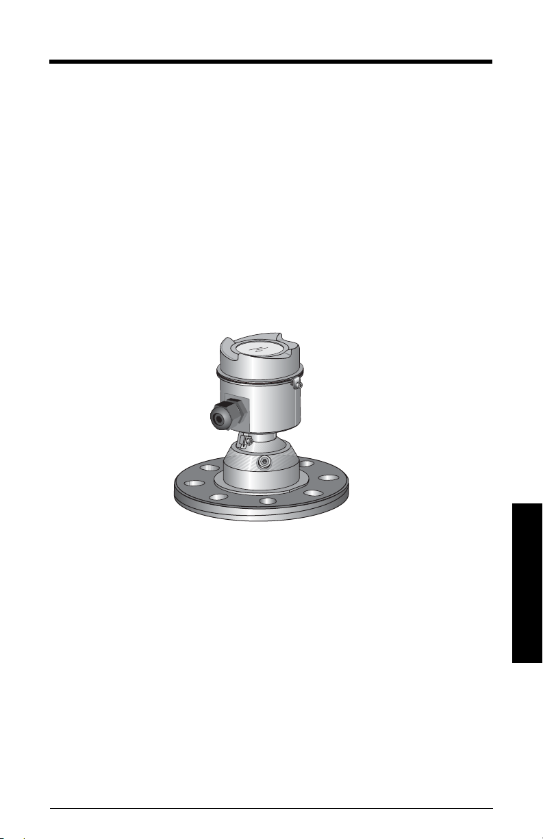
SITRANS LR560 Overview
SITRANS LR560 is a 2-wire, 78 GHz FMCW radar level transmitter for continuous
monitoring of solids and liquids in vessels to a range of 100 m (329 ft). The plug and play
performance is ideal for all solids applications, including those with extreme dust and
high temperatures to +200 °C (+392 °F). The device is an electronic circuit coupled to a
lens antenna and flange for quick and easy positioning.
The main benefits of using 78 GHz over devices using lower frequency are:
• very narrow beam, so device is insensitive to mounting nozzle interference and
vessel obstructions.
• short wavelength yields very good reflection properties on sloped solids, so aiming
towards material angle of repose is usually not necessary.
The technology is very tolerant to buildup on the lens antenna, however an air purge inlet
is provided for periodic cleaning if required.
SITRANS LR560 supports HART communication protocol, and SIMATIC PDM software.
Signals are processed using Process Intelligence which has been field-proven in over
1,000,000 applications worldwide (ultrasonic and radar).
Programming
SITRANS LR560 is very easy to install and configure via an optional graphical local
display interface. You can modify the built-in parameters either locally via the push
buttons or using the infra-red handheld programmer, or from a remote location using one
of the following options:
• HART (using 375 handheld Field Communicator, SIMATIC PDM, AMS, Pactware FDT/
DTM)
• PROFIBUS PA (using SIMATIC PDM, FDT [such as PACTware or Fieldcare]) (See
SITRANS LR560 (PROFIBUS PA) Instruction Manual for more information.)
• Foundation Fieldbus FF (using handheld 375 Field Communicator, FF host system or
AMS Device Manager) [See SITRANS LR560 (Foundation Fieldbus) Instruction
Manual for more information.]
Once programmed, the graphic Local Display Interface (LDI) can be removed if desired
and used to transfer parameters to multiple SITRANS LR560s.
A5E34647946 SITRANS LR560 (mA/HART) – OPERATING INSTRUCTIONS Page 7
Description

Local Display Interface (LDI)
• LDI may be ordered installed or added later as
an option
• can be mounted in 1 of 4 positions at 90 degree
intervals, for easy viewing after installation
• displays level and diagnostic information
including echo profile and trend over time
• backlit for easy viewing in dimly lit areas
• allows you to copy parameters from one device
to another
• provides high speed firmware transfer capabilities for future upgrades
Versions
Two different versions of the LR560 are available:
• 40 m range, +100 °C maximum process temperature
• 100 m range, +200 °C maximum process temperature
Applications
• solids and liquids bulk storage vessels
• cement powder, plastic powder/pellets, grain, flour, coal, and other applications
Approvals and Certificates
SITRANS LR560 is available with General Purpose approval, or for Hazardous areas. For
details, see
Approvals
on page 12.
Application
Typ e
Nonhazardous
Hazardous
Description
Page 8 SITRANS LR560 (mA/HART) – OPERATING INSTRUCTIONS A5E34647946
LR560 Version Approval Rating Valid for:
General
Purpose
Non-Sparking/
Energy Limited
Dust Ignition
Proof
Non-incendive
CSA
, FM, CE, C-TICK
US/C
ATEX II 3G Ex nA/nL IIC T4 Gc Europe
ATEX II 1D, 1/2D, 2D
IECEx Cert. SIR 09.0149X
Ex ta IIIC T139 °C Da
FM/CSA:
Class II, Div. 1, Groups E, F, G
Class III T4
FM/CSA:
Class I, Div. 2, Groups A, B, C, D T4
N. America,
Europe
Europe and
International
US/Canada
US/Canada

Specifications
Note: Siemens makes every attempt to ensure the accuracy of these specifications but
reserves the right to change them at any time.
Power
Nominal 24 V DC with
max. 550 Ohm loop resistance:
• Maximum 30 V DC
• 4 to 20 mA loop power
Performance
Reference operating conditions according to IEC 60770-1
• ambient temperature +15 to +25 °C (+59 to +77 °F)
• humidity 45% to 75% relative humidity
• ambient pressure 860 to 1060 mbar g (86 000 to 106 000 N/m
1)
Measurement Accuracy
• Maximum measured error 5mm (0.2") including hysteresis and
Frequency 78 to 79 GHz FMCW
Max. measurement range
• 40 m version 40 m (131 ft)
• 100 m version 100 m (328 ft)
Min. detectable distance 400 mm (15.7") from sensor reference point
Update time
5)
Influence of ambient temperature < 0.003%/K (average over full temperature range,
Long-term stability <0.1%/24 months
Dielectric constant of material measured
• for ranges up to 20 m (65.6 ft) minimum dK = 1.6
• for ranges up to 100 m (328 ft) minimum dK = 2.5
(measured in accordance with IEC 60770-1)
3)
For other configurations, see the chart under
power
on page 143
non-repeatability
2)
maximum 10 seconds, depending on setting for
Response Rate (2.4.1.)
referenced to maximum range)
2
4)
Loop
g)
1)
Reference conditions: Position Detect (2.7.3.3.) set to Center and Algorithm (2.7.3.1.) set to
True First Echo.
2)
Under severe EMI/EMC environments per IEC61326-1 or NAMUR NE21, the device error may
increase to a maximum of 25mm (1")
3)
From sensor reference point.
4)
See
Dimensions
5)
Reference conditions: Response Rate (2.4.1.) set to FAST
on page 13.
A5E34647946 SITRANS LR560 (mA/HART) – OPERATING INSTRUCTIONS Page 9
Specifications

Memory:
• non-volatile EEPROM
• no battery required
Interface
Analog output
• signal range 4 to 20 mA (±0.02 mA accuracy)
upper limit 20 to 22.6 mA adjustable
lower limit 3.56 to 4 mA adjustable
• fail signal 3.56 mA to 22.6 mA; or last value
• load Max. 550 Ω @ 24 V DC
Communication: HART
• Load 230 to 550 Ω, 230 to 500 Ω when connecting a
coupling module
• Max. Line Length
• Protocol HART2), Version 6.0
Configuration
• remote Siemens SIMATIC PDM or AMS Device Manager
• local Siemens infrared handheld programmer, local
1)
multi-wire: ≤ 1500 m (4921 ft)
(PC) or FDT such as PACTWARE
control buttons, or HART handheld communicator
Mechanical
Specifications
Optional removeable graphic LCD, with bar graph representing level
local display interface (LDI)
3)
Process Connections:
• universal stamped flange
4)
3"/80 mm, 4"/100 m, 6"/150 mm
materials 304 stainless steel, stamped
• universal flat-faced flange
4)
3"/80 mm, 4"/100 mm, 6"/150 mm
materials stainless steel 316L (1.4404 or 1.4435), or 304
• Aimer flange
4)
3"/80 mm, 4"/100 mm, 6"/150 mm
material polyurethane powder-coated cast aluminum
1)
Max. length depends on wire type. See www.hartcomm.org for more details.
2)
HART® is a registered trademark of HART Communication Foundation.
3)
Display quality will be degraded in temperatures below -20 °C (-4 °F) and above +65 °C (+149 °F).
4)
Mates with EN 1092-1 (PN16)/ASME B16.5 (150 lb)/JIS 2220 (10K) bolt hole pattern.
Page 10 SITRANS LR560 (mA/HART) – OPERATING INSTRUCTIONS A5E34647946

Enclosure
• construction 316L/1.4404 stainless steel
• conduit entry M20x1.5, or ½" NPT
• conduit entry connector M12 connector (shipped with M20 to M12 adaptor)
optional) or 7/8" connector (shipped with 1/2" NPT to 7/8"
adaptor)
• ingress protection Type 4X/NEMA 4X, Type 6/NEMA 6, IP68
• lid with window polycarbonate (window material)
• sun shield (optional) 304 stainless steel
Lens antenna material
• construction 40 m version PEI
100 m version PEEK
Air Purge Connection
• equipped with female 1/8" NPT fitting
Weight
• 3" stainless steel flange model 3.15 kg (6.94 lb)
Environmental
Note: Use appropriate conduit seals to maintain IP or NEMA rating.
• location indoor/ outdoor
• altitude 5000 m (16 404 ft) max.
• ambient temperature -40 to +80 °C (-40 to +176 °F)
• relative humidity suitable for outdoor
Type 4, 4X/NEMA 4, 4X, Type 6/NEMA 6, IP68
enclosure (see note above)
• installation category I
• pollution degree 4
Process
stainless
1)
Aimer flange
0.5 bar max.
–40 to +100 °C
(–40 to +212 °F)
–40 to +200 °C
(–40 to +392 °F)
Aimer flange
3.0 bar max
–40 to +100 °C
(–40 to +212 °F)
–40 to +120 °C
(–40 to +248 °F)
• temperature and pressure
Note: Universal stamped flanges are to be used for 0.5 bar max pressure only.
Versions
40 m
100 m
1)
Maximum and minimum temperatures are dependent on the process connection, antenna and
O-ring materials. Use of the Easy Aimer limits maximum temperature.
steel flange
–40 to +100 °C
(–40 to +212 °F)
–40 to +200 °C
(–40 to +392 °F)
A5E34647946 SITRANS LR560 (mA/HART) – OPERATING INSTRUCTIONS Page 11
Specifications

Approvals
Note: The device label lists the approvals that apply to your device.
•General CSA
, FM, CE, C-TICK
US/C
• Radio R&TTE (Europe), FCC, Industry Canada,
• Hazardous
Non-sparking/
Energy Limited
1)
(Europe/International) ATEX II 3G Ex nA/nL IIC T4 Gc
IECEx SIR 09.0149
1)
Dust Ignition Proof
(Europe/International) ATEX II 1D, 1/2D, 2D
Ex ta IIIC T139 oC Da IP68
IECEx SIR 09.0149X
2)
Dust Ignition Proof
(US/Canada) FM/CSA:
Class II, Div. 1, Groups E, F, G
Class III T4
Non-incendive
2)
(US/Canada) FM/CSA Class I, Div. 2,
Groups A, B, C, D, T4
Programmer (infrared keypad)
Notes:
• Battery is non-replaceable with a lifetime expectancy of 10 years in normal use.
• To estimate the lifetime expectancy, check the nameplate on the back for the serial
number. The first six numbers show the production date (mmddyy), for example,
serial number 032608101V.
Siemens Infrared IS (Intrinsically Safe) Hand Programmer for hazardous and all other
locations (battery is non-replaceable)
• approval FM/CSA Class I, II, III, Div. 1, Gr. A to G T6
ATEX II 1GD Ex ia IIC T4 Ga
Ex iaD 20 T135 °C
CE
IECEx SIR 09.0073 Ex ia IIC T4 Ga
Ex iaD 20 T135 °C
INMETRO Br-Ex ia IIC T4
• ambient temperature -20 to +50 °C (-5 to +122 °F)
• interface proprietary infrared pulse signal
• power 3 V lithium battery
• weight 150 g (0.3 lb)
• color black
• Part Number 7ML1930-1BK
1)
See
Non-Sparking/Energy Limited wiring (Europe) and Dust Ignition Proof wiring (Europe/
Specifications
International)
2)
See
on page 29 for more details.
Non-incendive and Dust Ignition Proof wiring (US/Canada)
on page 29.
Page 12 SITRANS LR560 (mA/HART) – OPERATING INSTRUCTIONS A5E34647946
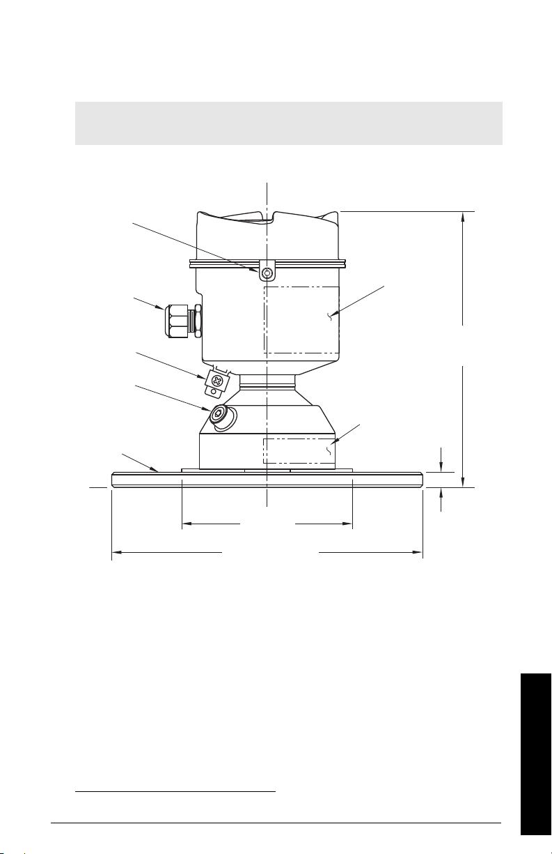
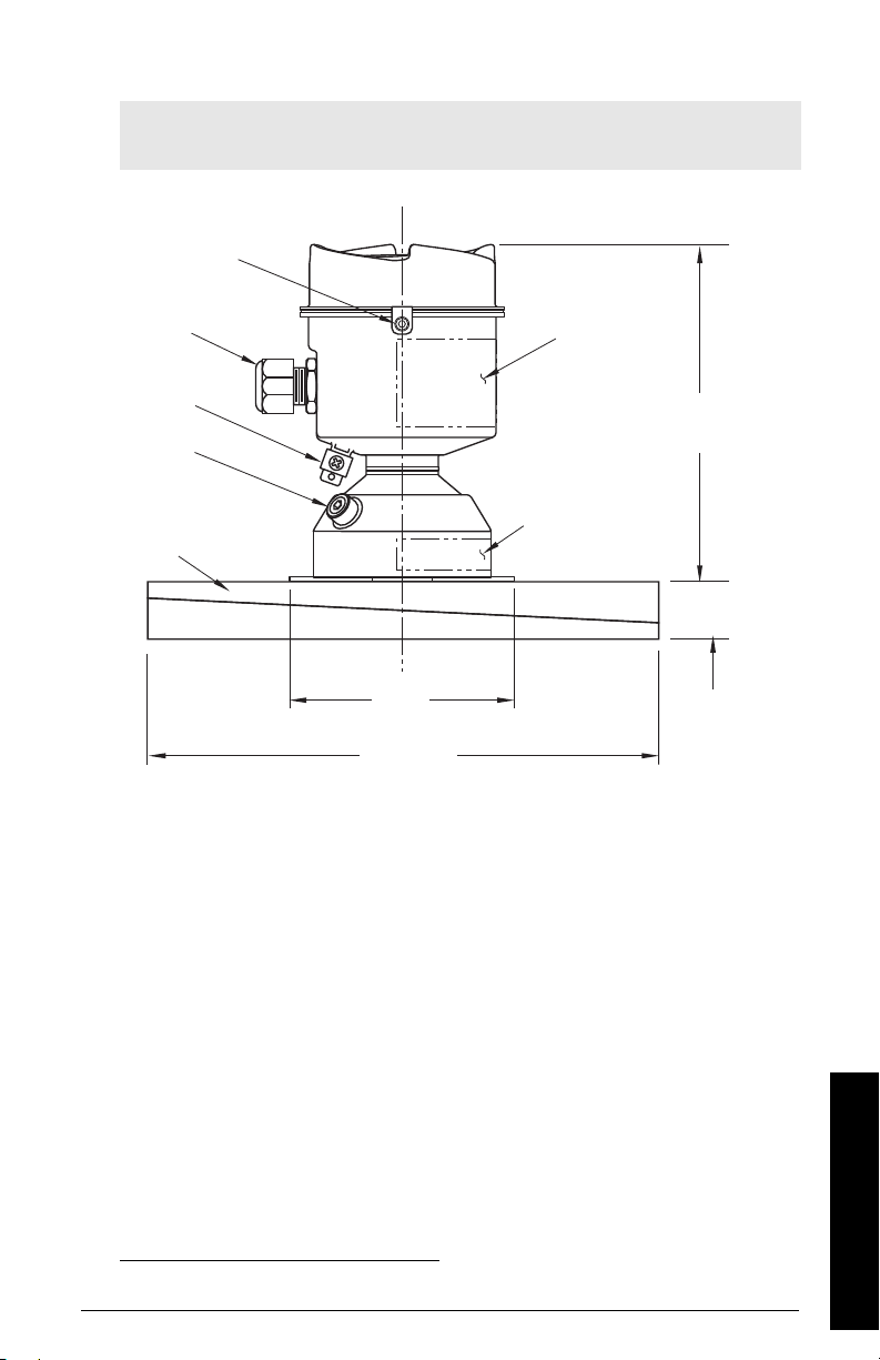
Dimensions
grounding
lug
purge inlet
process
connection:
flat-faced
flange
cable gland
1)
110 mm
(4.33")
176 mm
(6.93")
9.6 mm
(0.38")
3": 200 mm (7.87")
4": 229 mm (9.02")
6": 285 mm (11.22")
lid lock
sensor
reference
point
pressure/
temperature
related
information
device
label
SITRANS LR560 with stainless steel universal flat-faced flange
Note: Refer to
dimensions.
Universal flat-faced flange
on page 18 for bolt hole patterns and
1)
1)
Shipped with product, packed in a separate bag.
A5E34647946 SITRANS LR560 (mA/HART) – OPERATING INSTRUCTIONS Page 13
Specifications
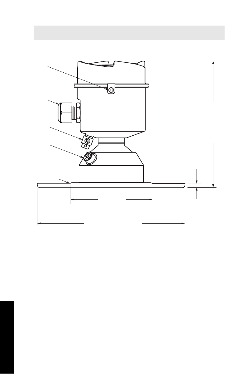
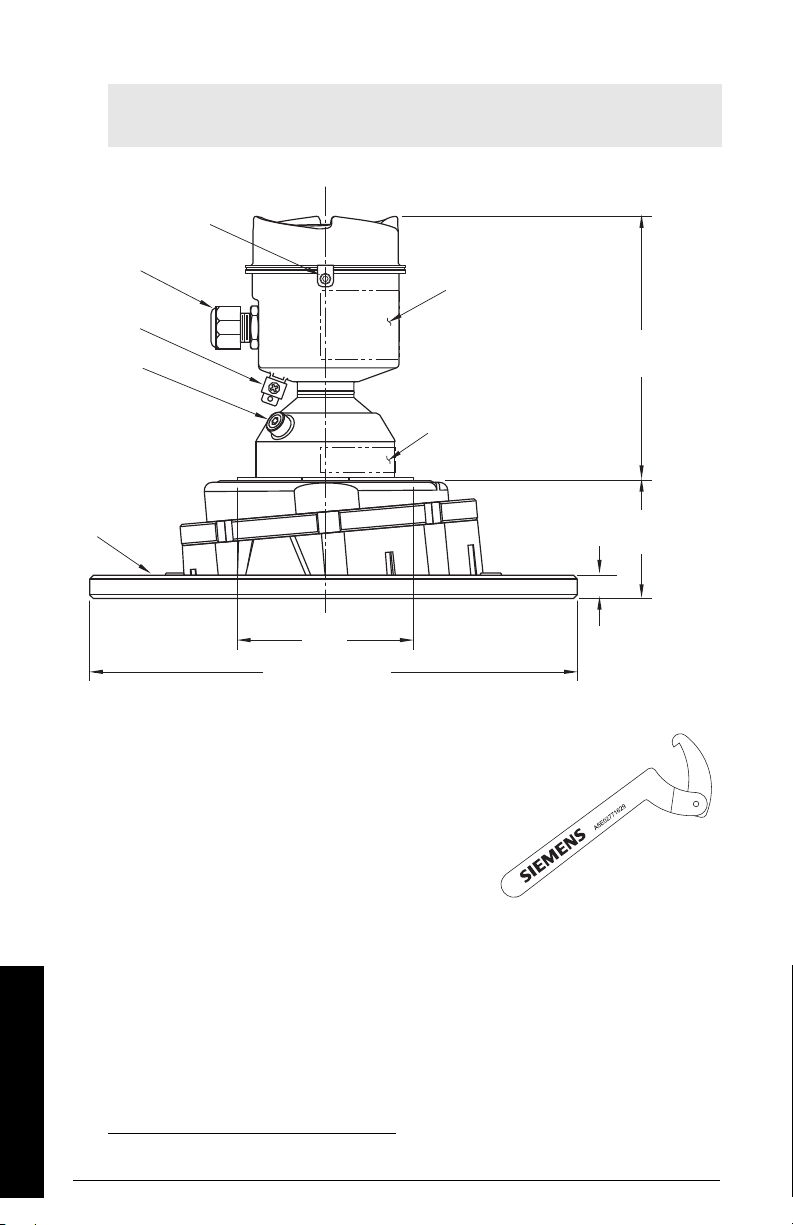
SITRANS LR560 with stainless steel universal stamped flange
110 mm
(4.33")
200 mm (7.87")
234 mm (9.21")
290 mm (11.42")
6 mm
(0.24")
176 mm
(6.93")
lid lock
cable gland
grounding
lug
purge
inlet
process
connection:
stamped
flange
Note: Refer to
dimensions.
Universal stamped flange
on page 19 for bolt hole patterns and
Specifications
Page 14 SITRANS LR560 (mA/HART) – OPERATING INSTRUCTIONS A5E34647946
SITRANS LR560 with 3" Aimer Flange
grounding
lug
purge inlet
process
connection:
aimer flange
cable gland
1)
110 mm
(4.33")
166.1 mm
(6.54")
200 mm
(7.87")
23.3 mm
(0.92"
sensor
reference
point
pressure/
temperature
related
information
lid lock
device
label
1)
Note: Refer to
dimensions.
Universal flat-faced flange
on page 18 for bolt hole patterns and
1)
Shipped with product, packed in a separate bag.
A5E34647946 SITRANS LR560 (mA/HART) – OPERATING INSTRUCTIONS Page 15
Specifications
SITRANS LR560 with 4 and 6" Aimer Flange
grounding
lug
purge
inlet
process
connection:
aimer flange
cable gland
1)
110 mm
(4.33")
166.1 mm
(6.54")
4": 229 mm (9.02")
6": 285 mm (11.22")
9.6 mm
(0.38")
sensor
reference
point
pressure/
temperature
related
information
4": 53.2 mm (2.09")
6": 60.0 mm (2.36")
lid lock
device
label
Note: Refer to
dimensions.
Universal flat-faced flange
on page 18 for bolt hole patterns and
Specifications
C Spanner
A C spanner, used to loosen the aimer locking ring, is
shipped with the device, packed separately.
1)
Shipped with product, packed in a separate bag.
Page 16 SITRANS LR560 (mA/HART) – OPERATING INSTRUCTIONS A5E34647946
1)

Process Connection Label (Pressure Rated Versions)
For pressure-rated versions only, the process connection label lists the following
information:
Item Sample Text
CONNECTION SERIES
ASME B16.5 / EN 1092-1
/ JIS B 2220
NOM. PIPE SIZE (DN) 4 INCH / 100mm
MAWP (PS) 3 BAR
DESIGN TEMP. (TS) 100 ºC
MIN. PROCESS 3 BAR AT -40 ºC
0F13589.5
TEST PRESSURE (PT) 5.2 BAR
TEST DATE 10/01/04
PROCESS SERIES 25785
WETTED NON-METALLIC PEI
WETTED METALLICS 304L
WETTED SEALS FKM / VQM
Comments/Explanation
Flange Series: dimensional pattern based on
ASME B16.5/EN 1092-1/JISB 2
220 flange standards
Nominal Pipe Size: based on 150#/PN16/10K
flange pressure classes
Maximum Allowable Working Pressure at
Design Temperature
Maximum Allowable Working Temperature
Minimum Wetted Process Conditions
Canadian Registration Number (CRN)
Production Test Pressure
Date of Pressure Test (Year/Month/Day)
Pressure Tag Family Series
Sensor Lens Material
Process Connection Material(s)
Seal Material(s)
A5E34647946 SITRANS LR560 (mA/HART) – OPERATING INSTRUCTIONS Page 17
Specifications
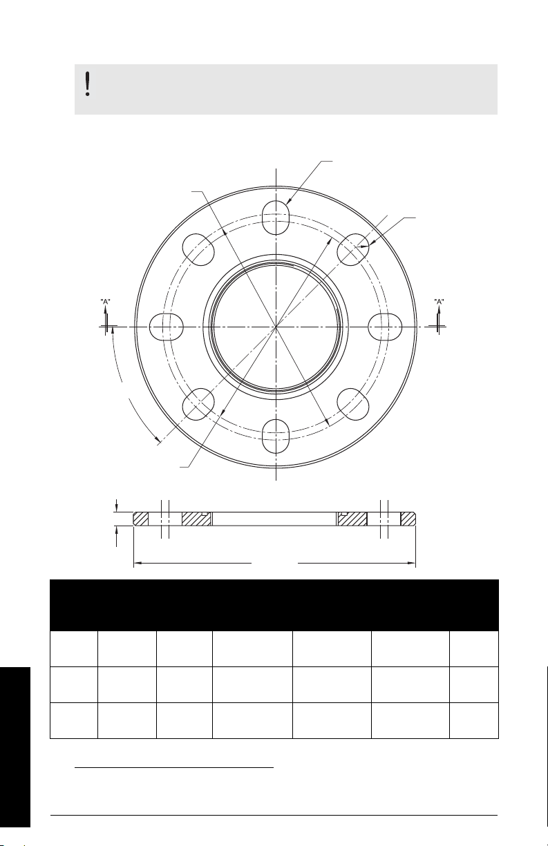
Universal flat-faced flange
bolt hole circle
min. diameter
number of slotted bolt holes
section A-A
thickness
bolt hole circle
max. diameter
45 °
flange O.D.
bolt hole radius
WARNING: The user is responsible for the selection of bolting and
gasket materials which will fall within the limits of the flange and its
intended use and which are suitable for the service conditions.
Universal flat-faced flange dimensions and Aimer
1)
Pipe
Size
80 mm
(3")
100mm
(4")
150 mm
(6")
Specifications
Page 18 SITRANS LR560 (mA/HART) – OPERATING INSTRUCTIONS A5E34647946
Flange
O.D.
200 mm
(7.87")
229 mm
(9.00")
285 mm
(11.22")
1)
Universal flanges mate with EN 1092-1 (PN16)/ASME B16.5 (150 lb)/JIS 2220 (10K) bolt
hole pattern.
Thick-
ness (s)
9.65 mm
(0.38")
9.65 mm
(0.38")
9.65 mm
(0.38")
Bolt Hole
Circle Max Ø
160 mm
(6.30")
191 mm
(7.52")
242 mm
(9.53")
Bolt Hole
Circle Min Ø
150 mm
(5.91")
175 mm
(6.89")
240 mm
(9.45")
Bolt Hole
radius
9.5 mm
(0.37" )
9.5 mm
(0.37")
11.5 mm
(0.45")
No. of
Slotted
Holes
8
8
8
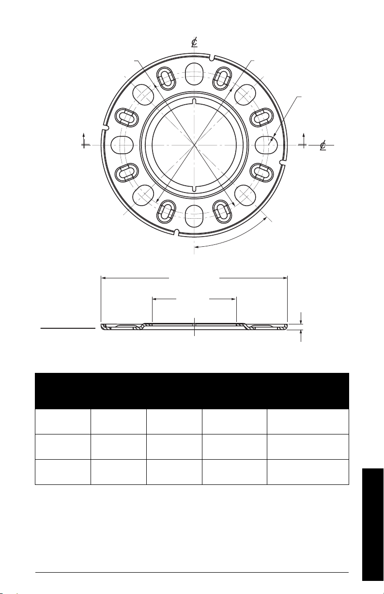
Universal stamped flange
SECTION A - A
"A""A"
45°
bolt hole circle
min. diameter
bolt hole
radius
flange O.D.
bolt hole circle max.
diameter
Universal stamped flange dimensions
A5E34647946 SITRANS LR560 (mA/HART) – OPERATING INSTRUCTIONS Page 19
Pipe
Size
80 mm
(3")
100 mm
(4")
150 mm
(6")
Flange O.D. (A)
± 11
200 mm
(7.87")
234 mm
(9.21")
290 mm
(11.42")
Bolt Hole Circle
max for slotted
holes (BMAX)
± 0.75
160 mm
(6.30")
191 mm
(7.5")
242 mm
(5.59")
Material: 304 stainless steel, gauge #12, finish to be RoHS compliant.
Bolt Hole Circle min
for slotted holes
(BMIN)
± 0.75
150 mm
(5.91")
175 mm
(6.89")
240 mm
(9.45")
Bolt Hole Radius (RBD)
± 0.25
9.5 mm
(0.37")
9.5 mm
(0.37")
11.5 mm
(0.45")
Specifications

Notes
Specifications
Page 20 SITRANS LR560 (mA/HART) – OPERATING INSTRUCTIONS A5E34647946

Installation
WARNINGS:
• Installation shall only be performed by qualified personnel and in
accordance with local governing regulations.
• SITRANS LR560 is to be used only in the manner outlined in this manual,
otherwise protection provided by the device may be impaired.
• Never attempt to loosen, remove, or disassemble process connection
or instrument housing while vessel contents are under pressure.
• The user is responsible for the selection of bolting and gasket materials
which will fall within the limits of the flange and its intended use and
which are suitable for the service conditions.
• Improper installation may result in loss of process pressure.
Notes:
• Refer to the device label for approval information.
• SITRANS LR560 units are pressure tested, meeting or exceeding the requirements of
the ASME Boiler and Pressure Vessel Code and the European Pressure Equipment
Directive.
• The serial numbers stamped in each process connection body provide a unique
identification number indicating date of manufacture.
Example: MMDDYY – XXX (where MM = month, DD = day, YY = year, and
XXX= sequential unit produced)
Further markings (space permitting) indicate flange configuration, size, pressure
class, material, and material heat code.
Installation
Pressure Equipment Directive, PED, 97/23/EC
Note: Pertains to pressure-rated version only.
SITRANS LR560 Radar Level Measurement instrument falls below the limits of Article 3,
sections 1&2 of the Pressure Equipment directive (PED, 97/23/EC), as a category I
pressure accessory. However, in accordance with PED, 97/23/EC, Article 3, section 3, this
equipment has been designated and manufactured in accordance with Sound
Engineering Practice (SEP) (see EU Commission Guideline 1/5).
A5E34647946 SITRANS LR560 (mA/HART) – OPERATING INSTRUCTIONS Page 21
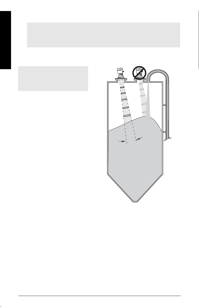
Mounting location
emission
cone
4°
Notes:
• Correct location is key to a successful application.
• Avoid reflective interference from vessel walls and obstructions by following the
guidelines below.
Installation
Nozzle location
Notes:
• For details on avoiding false
echoes, see
on page 137.
Beam angle
• Beam angle is the width of
• The peak energy density is
• There is a signal transmitted
Shaper Mode (2.8.4.)
the cone where the energy
density is half of the peak
energy density.
directly in front of and in line
with the antenna.
outside the beam angle,
therefore false targets may
be detected.
Emission cone
• Keep emission cone free of
interference from ladders,
pipes, I-beams or filling
streams.
• Avoid central locations on
tall, narrow vessels.
Page 22 SITRANS LR560 (mA/HART) – OPERATING INSTRUCTIONS A5E34647946
Environment
ambient temperature
–40 °C to +80 °C
(–40 °F to +176 °F)
process temperature
–40 to +100 °C (–40 to +212 °F) or
–40 to +200 °C (–40 to +392 °F) depending on the version
• Provide easy access for
viewing the display and
programming via the
hand programmer.
• Provide an environment
suitable to the housing
rating and materials of
construction.
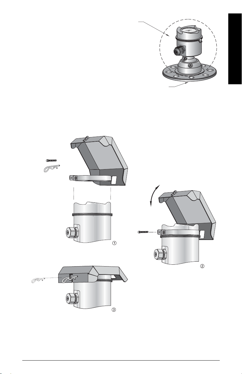
Sun Shield
The LR560 display can be protected by an optional sun shield if the instrument will be
mounted in direct sunlight.
Installation
A5E34647946 SITRANS LR560 (mA/HART) – OPERATING INSTRUCTIONS Page 23
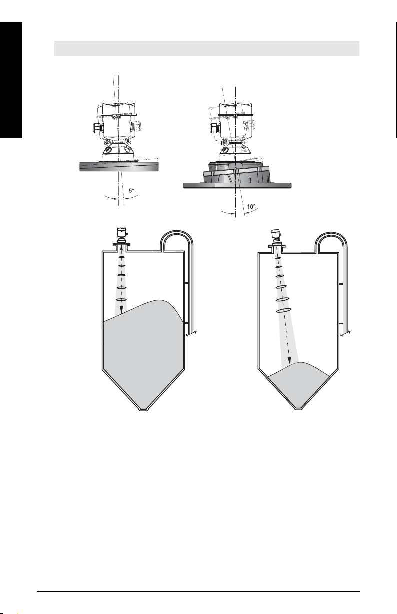
Aimer Adjustment
Aimer
Aiming is not
required for signal
optimization with
78 GHz frequency.
Aiming will assist
in measuring
material in the
cone.
Note: Aiming will assist in measuring material in the cone.
Installation
3" flange 4 and 6" flange
Page 24 SITRANS LR560 (mA/HART) – OPERATING INSTRUCTIONS A5E34647946
1. For 4" and 6" Aimer: Loosen the set screws in the locking ring.
Holding the electronics enclosure firmly, loosen the Aimer locking ring using the
supplied C spanner, until the LR560 drops down slightly. The enclosure can then be
turned freely.
2. Direct SITRANS LR560 so the antenna is pointed at an angle perpendicular to the
material surface, if possible.
3. When the desired position is reached, re-tighten the locking ring using the C
spanner, and tighten set screws.
 Loading...