

Siemens Sitrans LR400 Instruction Manual
Instruction Manual May 2008
sitrans
LR400

Safety Guidelines: Warning notices must be observed to ensure personal safety as well as that of
others, and to protect the product and the connected equipment. These warning notices are
accompanied by a clarification of the level of caution to be observed.
Qualified Personnel: This device/system may only be set up and operated in conjunction with this
manual. Qualified personnel are only authorized to install and operate this equipment in accordance with
established safety practices and standards.
Unit Repair and Excluded Liability:
• The user is responsible for all changes and repairs made to the device by the user or the user’s
agent.
• All new components are to be provided by Siemens Milltronics Process Instruments Inc.
• Restrict repair to faulty components only.
• Do not reuse faulty components.
Warning: This product can only function properly and safely if it is correctly transported, stored,
installed, set up, operated, and maintained.
This product is intended for use in industrial areas. Operation of this equipment in a residential area
may cause interference to several frequency based communications.
Note: Always use product in accordance with specifications.
Copyright Siemens Milltronics Process
Disclaimer of Liability
Instruments Inc. 2008. All Rights Reserved
This document is available in bound version and in
electronic version. We encourage users to purchase
authorized bound manuals, or to view electronic versions
as designed and authored by Siemens Milltronics Process
Instruments Inc. Siemens Milltronics Process Instruments
Inc. will not be responsible for the contents of partial or
whole reproductions of either bound or electronic
versions.
While we have verified the contents of this
manual for agreement with the
instrumentation described, variations
remain possible. Thus we cannot
guarantee full agreement. The contents of
this manual are regularly reviewed and
corrections are included in subsequent
editions. We welcome all suggestions for
improvement.
Technical data subject to change.
MILLTRONICS®is a registered trademark of Siemens Milltronics Process Instruments Inc.
Contact SMPI Technical Publications European Authorized Representative
at the following address:
Technical Publications Siemens AG
Siemens Milltronics Process Instruments Inc. Industry Sector
1954 Technology Drive, P.O. Box 4225 76181 Karlsruhe
Peterborough, Ontario, Canada, K9J 7B1 Deutschland
Email: techpubs.smpi@siemens.com
• For a selection of Siemens Milltronics level measurement manuals, go to:
www. siemens.com/processautomation. Under Process Instrumentation, select
Measurement
• For a selection of Siemens Milltronics weighing manuals, go to:
www. siemens.com/processautomation. Under Weighing Technology, select
Weighing Systems
and then go to the manual archive listed under the product family.
and then go to the manual archive listed under the product family.
Level
Continuous
© Siemens Milltronics Process Instruments Inc. 2008

Table of Contents
Table of Conetns
General Information ........................................................................................................... 1
Safety Notes .............................................................................................................................................1
The Manual ...............................................................................................................................................1
Abbreviations and Identifications .......................................................................................................2
SITRANS LR400 .......................................................................................................................................3
Structure ....................................................................................................................................................3
System Implementation .........................................................................................................................4
Programming ............................................................................................................................................4
Specifications ...................................................................................................................... 5
SITRANS LR400 .............................................................................................................................5
Dimensions ...............................................................................................................................................9
Air Purging System (Optional) ........................................................................................ 13
Installation ......................................................................................................................... 15
Mounting Location ................................................................................................................................15
Beam Width ..................................................................................................................................16
Correct Installation in Mounting Nozzle ................................................................................16
Electrical Connection ...........................................................................................................................17
mmmmm
Start Up ............................................................................................................................... 19
Self-test ....................................................................................................................................................19
Multi-display ...........................................................................................................................................19
Local Programming ...............................................................................................................................19
Auto-Setup ..............................................................................................................................................19
Operation ............................................................................................................................20
General Information ..............................................................................................................................20
Operating SITRANS LR400 ..................................................................................................................20
Selecting a Parameter .........................................................................................................................21
Structure of Parameters ............................................................................................................21
Changing a Parameter Value ..............................................................................................................22
Disabling and Enabling Programming ..............................................................................................23
Parameter Operating Examples .........................................................................................................24
Parameters (HART) ...........................................................................................................26
Vessel Functional Dimensions ...........................................................................................................27
Required Parameters ............................................................................................................................27
Additional Parameters .........................................................................................................................29
Parameters (PROFIBUS PA) ............................................................................................ 68
Troubleshooting ................................................................................................................. 81
Classification of Faults .........................................................................................................................81
Self-test ....................................................................................................................................................81
7ML19985FH06 SITRANS LR400 (7ML5421) – INSTRUCTION MANUAL i

Symptoms, Causes and Their Remedy ............................................................................................81
Fault Messages .....................................................................................................................................82
Unit Repair and Excluded Liability ..........................................................................................84
Antenna Maintenance ..................................................................................................... 86
mmmmm
Cleaning the Antenna ..........................................................................................................................86
Hazardous Installation .....................................................................................................87
Table of Con tent s
Appendix I ..........................................................................................................................88
Ambient/Operating Temperature Specification .............................................................................88
Appendix II ......................................................................................................................... 89
Process Pressure/Temperature De-rating ......................................................................................89
Appendix III ........................................................................................................................91
Measuring Principle .............................................................................................................................91
Appendix IV ........................................................................................................................93
HART Communications for SITRANS LR400 ..................................................................................93
HART Device Description (DD) .................................................................................................93
SIMATIC Process Device Manager (PDM) ...........................................................................93
HART Communicator 275/375: ..................................................................................................94
Appendix V .........................................................................................................................97
PROFIBUS PA Communications for SITRANS LR400 ...................................................................97
Device Description ......................................................................................................................97
The GSD file ..................................................................................................................................97
Bus address (Device Address) .................................................................................................97
Bus Termination ...........................................................................................................................98
Power Demands ..........................................................................................................................98
Cyclic versus Acyclic Data ........................................................................................................98
Cyclic Data ....................................................................................................................................98
Status Word ............................................................................................................................... 100
Extended Diagnostics ..............................................................................................................101
Acyclic Data ................................................................................................................................101
Configuration Example: ............................................................................................................101
Appendix VI: Firmware Revision History ...................................................................102
Glossary ............................................................................................................................ 104
Index .................................................................................................................................. 107
ii SITRANS LR400 (7ML5421) – INSTRUCTION MANUAL 7ML19985FH06

General Information
Safety Notes
Special attention must be paid to warnings and notices highlighted from the rest of the
text by grey boxes.
WARNING: relates to a caution symbol on the product, and means
that failure to observe the necessary precautions can result in
death, serious injury, and/or considerable material damage.
WARNING: means that failure to observe the necessary
precautions can result in death, serious injury, and/or considerable
material damage.
CAUTION: means that failure to observe the necessary precautions can
result in considerable material damage.
General Information
mmmmm
Note:
manual.
• These instructions do not claim to cover all details or variations in equipment, or to
• For further information or to resolve issues not covered in the manual, consult your
means important information about the product or that part of the operating
provide for every possible contingency that may arise during installation, operation,
or maintenance.
Siemens Milltronics representative.
The Manual
IMPORTANT: All specifications are subject to change without notice.
Please ensure that any safety-related information is confirmed with a
qualified Siemens Milltronics representative.
WARNINGS:
• Changes or modifications not expressly approved by Siemens Milltronics
could void the user’s authority to operate the equipment.
• This equipment is intended to be used only in fully enclosed metal and
concrete containers.
Note: This equipment has been tested and found to comply with the limits for a Class
A digital device, pursuant to Part 15 of the FCC Rules. These limits are designed to
provide reasonable protection against harmful interference when the equipment is
operated in a commercial environment. This equipment generates, uses, and can
radiate radio frequency energy and, if not installed and used in accordance with the
instruction manual, may cause harmful interference to radio communications.
Operation of this equipment in a residential area is likely to cause harmful
interference in which case the user will be required to correct the interference at his
own expense.
7ML19985FH06 SITRANS LR400 (7ML5421) – INSTRUCTION MANUAL Page 1

This manual will help you set up your SITRANS LR400 for optimal performance. This
manual applies to the HART and PROFIBUS SITRANS LR400. For HART parameters,
please see page 26. For PROFIBUS PA parameters, see page 68. We always welcome
suggestions and comments about manual content, design, and accessibility.
Please direct your comments to techpubs.smpi@siemens.com. For the complete library of
Siemens Milltronics manuals, go to www.siemens.com/processautomation.
WARNINGS:
• Installation shall only be performed by qualified personnel and in
accordance with local governing regulations.
• The SITRANS LR400 is to be used only in the manner outlined in this
manual, otherwise protection provided by equipment may be impaired.
Note: This product is intended for use in industrial areas. Operation of this equipment
in a residential area may cause interference to several frequency based
communications.
mmmmm
Qualified personnel
General Information
Qualified personnel are familiar with the installation, commissioning, and operation of
this equipment. In addition the person must be:
• trained and authorized to operate and service equipment/systems in accordance
with established safety procedures relating to electrical circuits, high pressures and
aggressive media.
• trained in the proper care and use of protective equipment in accordance with
established safety practices.
• trained in rendering first aid.
Abbreviations and Identifications
Short form Long form Description
CE / FM / CSA Conformitè Europèene / Factory Mutual /
Canadian Standards Association
ESD Electrostatic Discharge
HART® Highway Addressable Remote Transducer
IS Intrinsically Safe safety approval
safety approval
LRV Lower Range Value value for process
PED Pressure Equipment Directive safety approval
URV Upper Range Value value for process full
1.
100% is most commonly set to 20 mA and 0% to 4 mA.
HART is a registered trademark of the HART Communication Foundation.
Page 2 SITRANS LR400 (7ML5421) – INSTRUCTION MANUAL 7ML19985FH06
empty level
(symbol 4 mA)
level (symbol 20 mA)
1
1
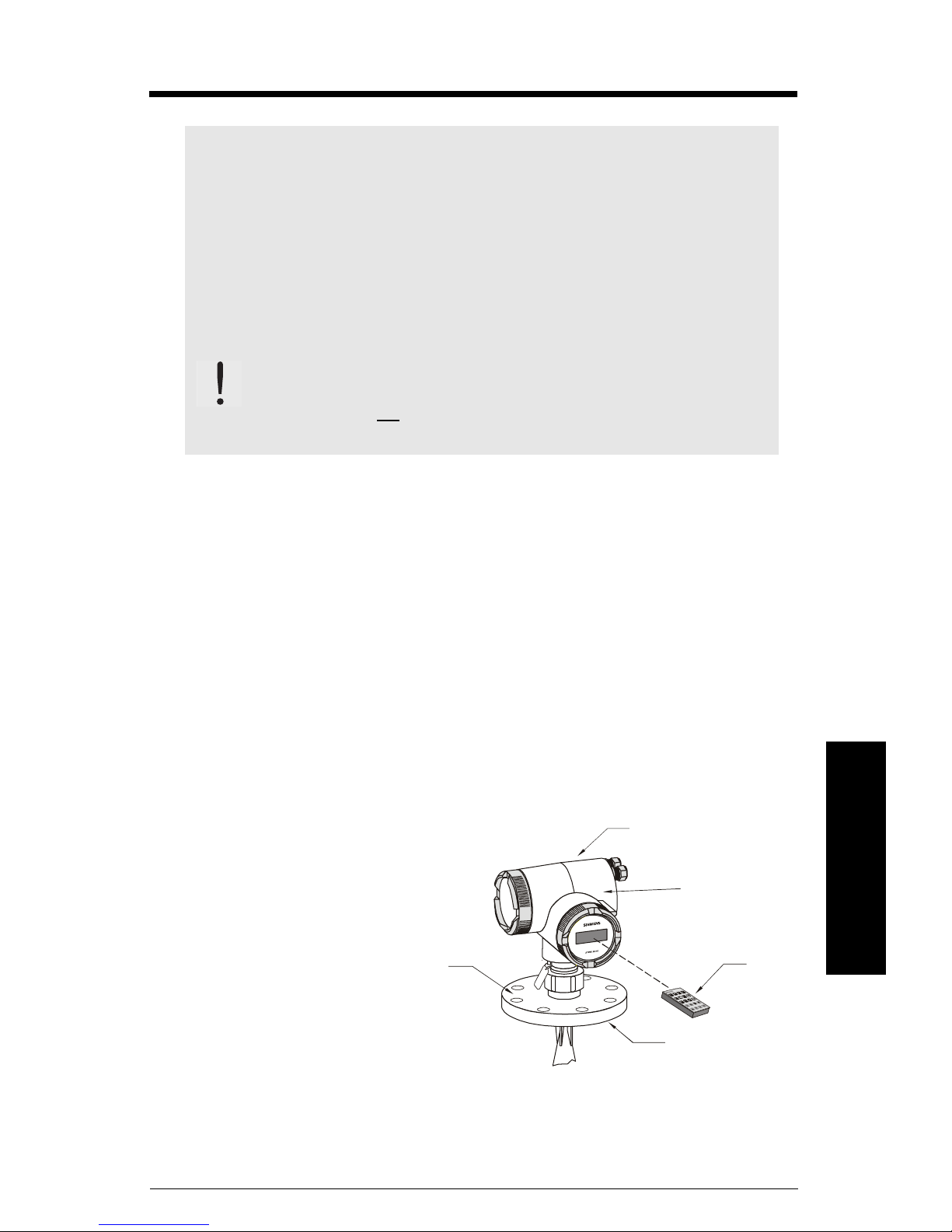
SITRANS LR400
r
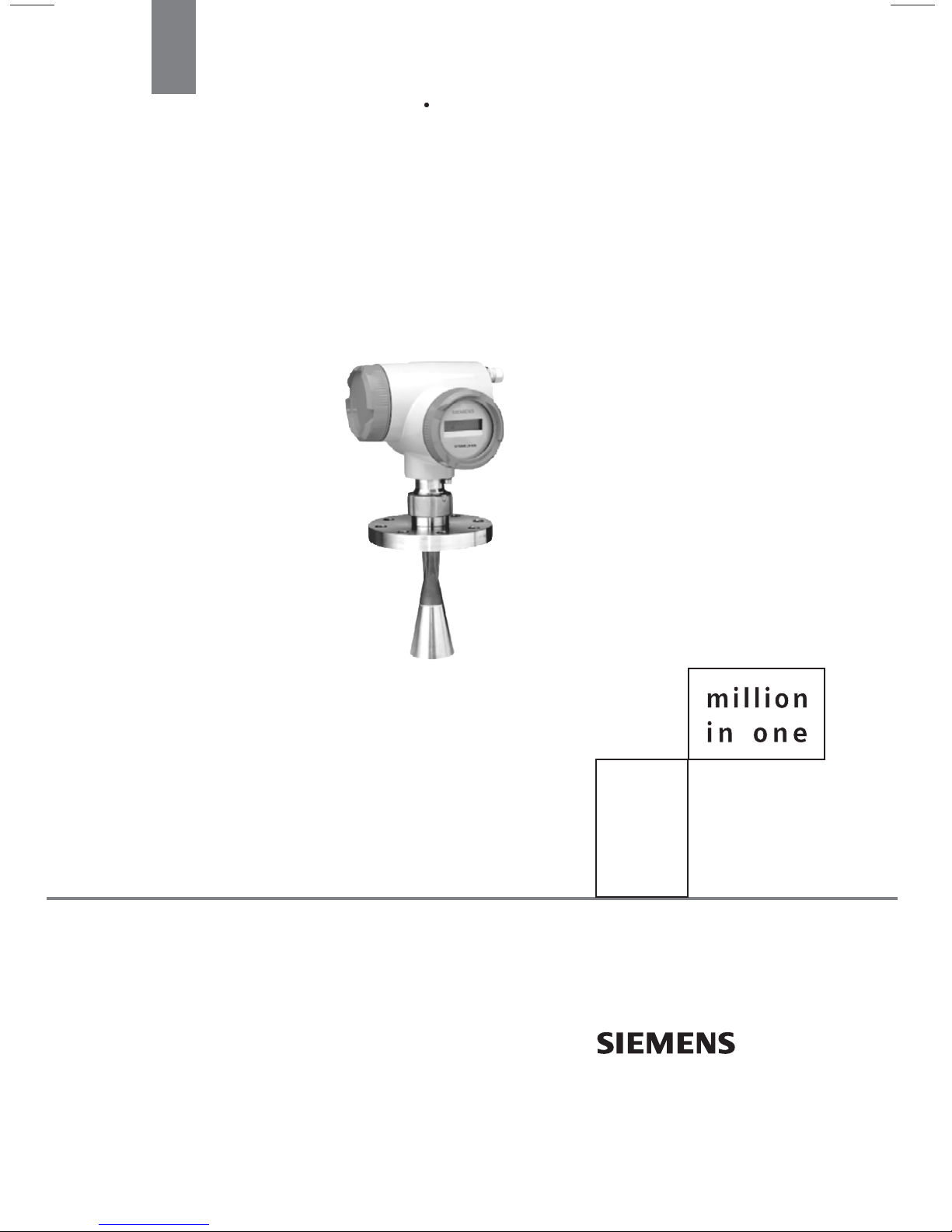
SITRANS LR400 is a long-range FMCW radar level transmitter. It is suitable for use in
liquids and solids, for low dielectric liquids, and high pressure applications or applications
with extreme dust. This version also incorporates a purging option for sticky solids
applications. The narrow antenna beam results in a sharp emission cone, which makes
SITRANS LR400 quite insensitive to vessel interferences.
Note: This manual applies to the 7ML5421 version only. Please see Instruction
Manual 7ML19985JC02 for information about the SITRANS LR400, 7ML5420
version.
General Information
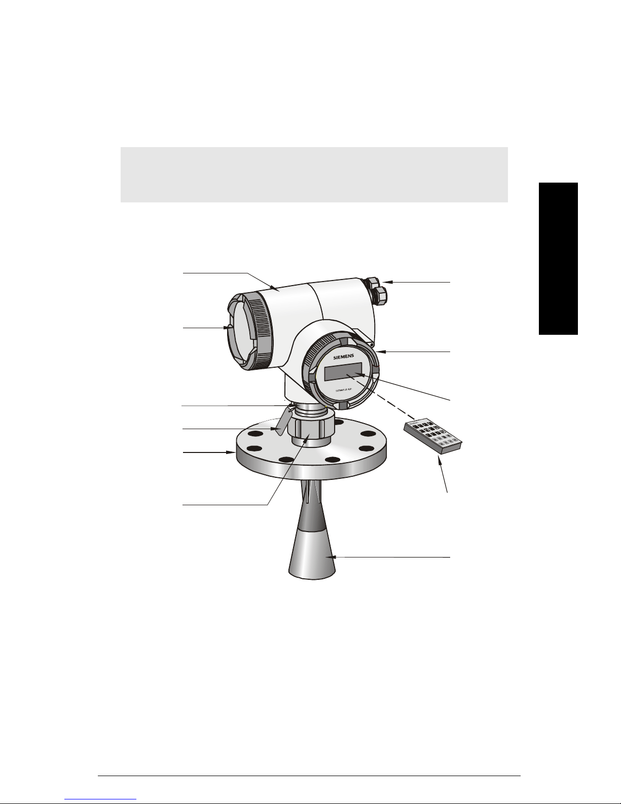
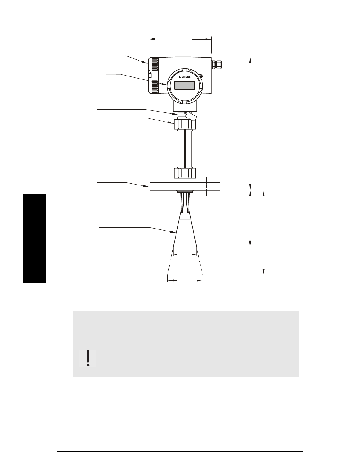
Structure
housing
connection
cover
intermediate
flange
device tag
process flange
threaded ring
mmmmm
cable gland
electronics cove
display module
infra-red hand
programmer
(ordered
separately)
The terminals for the power cable and the signal cable are behind the connection cover
on the left side of the housing. The signal cable must be fed in from the right through the
cable glands.
The end of the antenna must reach inside the vessel through the vessel nozzle (see
page 16).
If the device is rotated, return the orientation of the housing to its previous position with
reference to the enclosure, to ensure similar performance.
7ML19985FH06 SITRANS LR400 (7ML5421) – INSTRUCTION MANUAL Page 3
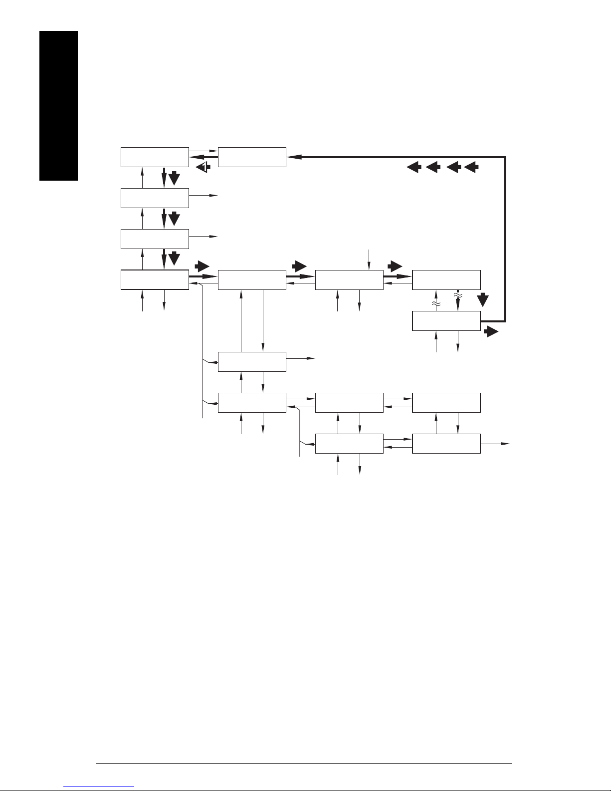
horn antenna
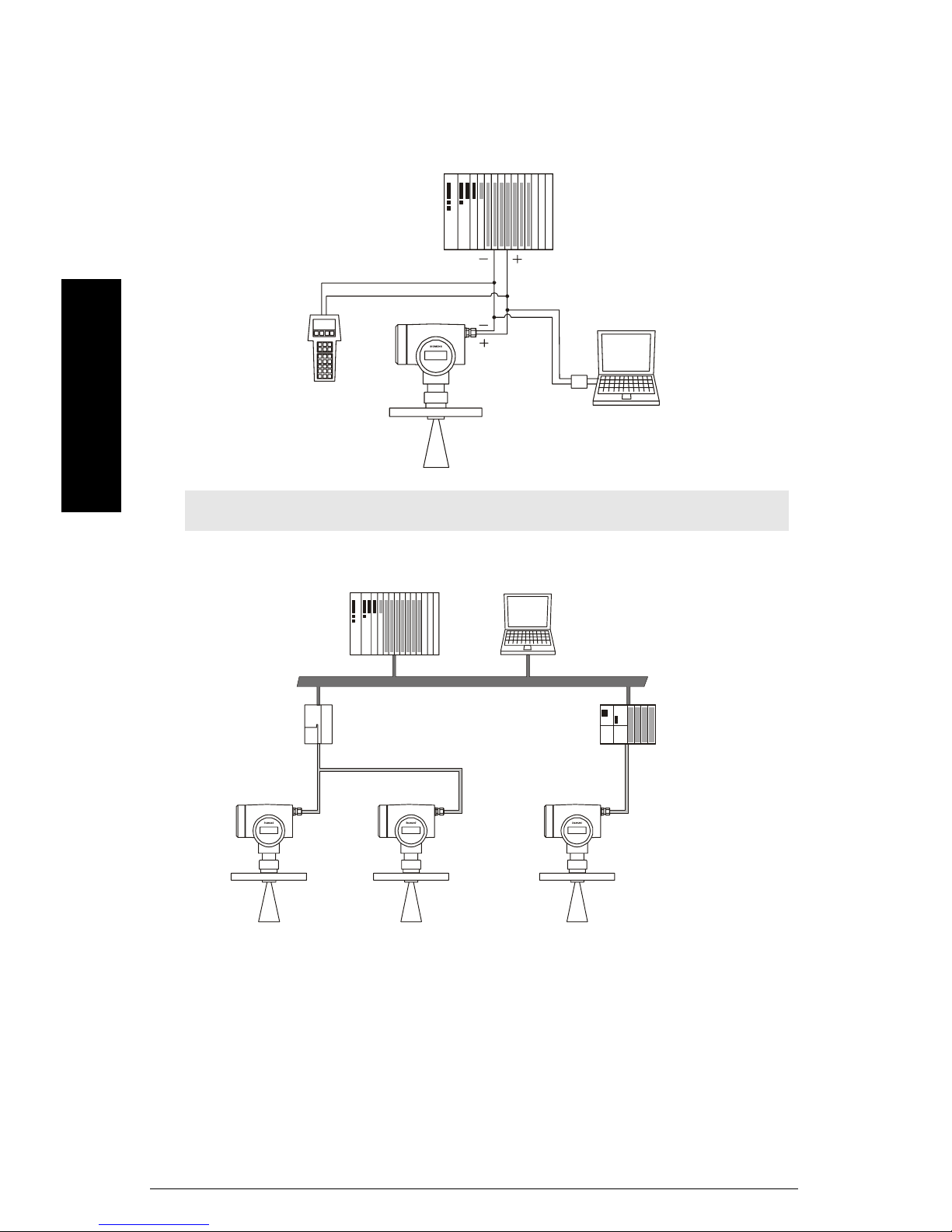
System Implementation
SITRANS LR400 supports HART communication protocol, and SIMATIC PDM software.
Typical PLC/mA configuration with HART
PLC with mA
input card
HART
HART Communicator 275
SITRANS LR 400
mmmmm
SITRANS LR400
General Information
Note: A 250 ohm loop resistor may be required, depending on PLC input resistance.
PC/laptop with HART
modem running PDM
Typical PLC/mA configuration with PROFIBUS PA
Class 1
Master
DP/PA
Coupler
SITRANS LR 400 SITRANS LR 400 SITRANS LR 400
PLC
PROFIBUS PA
SITRANS LR400
SITRANS LR400
PDM
SITRANS LR400
Programming
Class 2
Master
ET200
HART
SITRANS LR400 carries out its level measurement function according to the set of built-in
parameter tables. You can make parameter changes via the hand programmer, a PC
running SIMATIC PDM or a HART handheld communicator.
Page 4 SITRANS LR400 (7ML5421) – INSTRUCTION MANUAL 7ML19985FH06

Specifications
Note: Siemens Milltronics makes every attempt to ensure the accuracy of these
specifications, but reserves the right to change them at any time.
SITRANS LR400
Power
Power Supply
• 100 to 230 V AC, ±15%, 50/60 Hz, 6 W
• 24 V DC, +25/-20%, 6 W
• Fuse (AC) SI1 Fast acting ceramic, 4 x 20 mm, 1 A, 250 V AC
• Fuse (DC) SI1 Fast acting ceramic, 4 x 20 mm, 2 A, 250 V AC
Performance
SI2 Slow-Blow, 4 x 20 mm, 0.63 A, 250 V AC
SI2 Slow-Blow, 4 x 20 mm, 0.63 A, 250 V AC
• Frequency 25 GHz nominal
• Measuring range 0.35 to 50 m (1.15 to 164 ft)
Measured value error (under reference conditions)
• Measuring error ≤ ± 5 mm (0.2") at 1 to 10 m (3.3 to 32.8 ft.) distance
≤
± 15 mm (0.6") at 10 to 50 m (32.8 to 164 ft) distance
•Dead band
• Additional contribution of ≤ 0.1%
analog output
• Long-term stability ≤
• Repetitive accuracy ≤ ± 1 mm at 0 to 50 m, damping ≥ 1 s
1
0 to 350 mm from bottom edge of flange
± 1 mm/year
Interface
• Analog output (Not applicable to PROFIBUS PA option)
Signal range 4 to 20 mA
Fail signal 3.6 mA; 22.5 mA or last value
Load Max. 600 Ω; (330 Ω for [ia] versions, Area classification
options G, L, P, S)
2
, for HART3 communication min. 230 Ω
Specifications
mmmmm
1.
For solids applications, setting a dead band of 1 m is recommended because of
lower reflectivity and increased angles of repose.
2.
See Selection and Ordering Data sheet
3.
HART®is a registered trademark of HART Communication Foundation.
7ML19985FH06 SITRANS LR400 (7ML5421) – INSTRUCTION MANUAL Page 5

Relay Configurable as a device status or limit value
(level, volume, mass)
Either NCC or NOC function
max. 50 V DC, max. 200 mA, rating max. 5 W.
Self-resetting fuse, R
= 9 Ω
i
• Electrical isolation Outputs electrically isolated from the power supply and
from each other
• Display LCD, two lines of 16 characters each,
configurable for the following displays:
level, volume, mass, amplitude, digital output,
temperature, validity, signal-to-noise ratio
Programmer (infrared keypad)
Siemens Milltronics Infrared IS (Intrinsically Safe) hand programmer for hazardous and
all other locations (battery is non-replaceable)
• approval: ATEX II 1 G, EEx ia IIC T4, certificate SIRA 01ATEX2147
CSA and FM Class I, Div. 1, Gr. A, B, C, D T6 @ max. ambient
temperature of 40 °C (104 °F)
• ambient temperature: −20 to 40 °C (−5 to 104 °F)
• interface: proprietary infrared pulse signal
• power: 3 V lithium battery
• weight: 150 g (0.3 lb)
mmmmm
•color: black
Mechanical
Specifications
Flange
• Process Connection Flange DIN 2527, ANSI B16.5, or JIS B2238 equivalent bolt
pattern (See page 11 for flange dimensions.)
• Materials of the wetted Stainless steel 316/316L flange and 304 horn, PTFE
parts – in contact with emitter (or glass/PTFE, Zone 0 and Zone 20 devices)
the process
• Pressure (vessel) Varies with connection type. Refer to Appendix IV for
specifications.
• Horn types Short horn, 74 mm (2.9") diameter
Long horn, 93 mm (3.7") diameter
Page 6 SITRANS LR400 (7ML5421) – INSTRUCTION MANUAL 7ML19985FH06

Weight
• Weight of instrument and flange
Process Connection Weight
DN80 PN16, flat faced 11.9 kg (26.1 lbs)
DN80 PN40, flat faced 12.9 kg (28.4 lbs)
DN100 PN16, flat faced 13.2 kg (28.9 lbs)
DN100 PN40, flat faced 15.5 kg (34.1 lbs)
DN150 PN16, flat faced 19.2 kg (42.1 lbs)
DN150 PN40, flat faced 24.1 kg (43.1 lbs)
3", 150 lb class, raised faced 12.2 kg (26.8 lbs)
3", 300 lb class, raised faced 14.3 kg (31.5 lbs)
4", 150 lb class, raised faced 14.8 kg (32.5 lbs)
4", 300 lb class, raised faced 20.2 kg (44.4 lbs)
6", 150 lb class, raised faced 20.1 kg (44.2 lbs)
6", 300 lb class, raised faced 31.8 kg (69.9 lbs)
JIS DN80 10K, flat faced 11.9 kg (26.1 lbs)
JIS DN100 10K, flat faced 13.2 kg (28.9 lbs)
JIS DN150 10K, flat faced 19.2 kg (42.1 lbs)
Universal, 3" / 80 mm, flat faced, 0.5 bar maximum (purge option) 10.9 kg (24 lbs)
Universal, 4" / 100 mm, flat faced, 0.5 bar maximum (purge option) 12.7 kg (28 lbs)
Universal, 6" / 150 mm, flat faced, 0.5 bar maximum (purge option) 15.0 kg (33 lbs)
WARNING: This product is designated as a Pressure Accessory per
Directive 97/23/EC and is not intended for use as a safety device.
Enclosure
• construction Die-cast aluminum, painted (polyester powder-coated)
• conduit 2 x M20
or 2 x ½” NPT (option)
• ingress protection Type 4X/NEMA 4X, Type 6/NEMA 6, IP67
Environmental
2
1
• location indoor/outdoor
• altitude 2000 m (6562 ft) max
• ambient temperature
3
-40 to 65 °C (-40 to 149 °F)
• relative humidity suitable for outdoor (Type / NEMA 4X, 6/ IP67)
• installation category II
• pollution degree 4
• Perm. ambient -40 to 65 °C (-40 to 149 °F) (non-hazardous version)
temperature LCD: -10 to 55 °C (14 to 131 °F)
Observe the temperature classes in hazardous areas!
WARNING: Materials of construction are chosen based on their chemical
compatibility (or inertness) for general purposes. For exposure to specific
environments, check with chemical compatibility charts before installing.
Specifications
mmmmm
1.
Use only approved, suitable sized hubs for watertight applications.
2.
See Process/Ambient de-rating curves in Appendix III.
3.
-20 °C (-4 °F) temperature rating available on SITRANS LR400 with ATEX rating.
7ML19985FH06 SITRANS LR400 (7ML5421) – INSTRUCTION MANUAL Page 7

Process
• Process Temperature -40 to 200 °C (-40 to 392 °F)
Optional (7ML5421 version) -40 to 250 °C (-40 to 482 °F)
• Pressure (vessel) Varies with connection type. Refer to Appendix IV for
specifications.
Communication
• Communication: HART
Load 230 to 600 Ω, 230 to 500 Ω when connecting a coupling
module
Line two-wire shielded: ≤ 3000 m
multi-wire shielded: ≤ 1500 m
Protocol HART, Version 5.1
• Communication: PROFIBUS PA
Protocol Layer 1 and 2 PROFIBUS PA,
technology: IEC 61158-2, slave-functionality
Device Class A
Device Profile 3.0
• Software for PC/Laptop Windows 95/98/2000/XP or NT 4.0
SIMATIC® PDM
Approvals (verify against device nameplate)
• Explosion Protection Certificate No. PTB 00 ATEX 1024
mmmmm
Specifications
*Refer to device II 1/2G EEx d IIC T6II 2G EEx d IIC T6
nameplate II 1/2G EEx dem IIC T6II 2G EEx dem IIC T6
II 1/2G EEx dem [ib] IIC T6II 2G EEx dem [ib] IIC T6
II 1/2G EEx dem [ia] IIC T6II 2G EEx dem [ia] IIC T6
FM/CSA Class I, Div. 1, Groups B, C, D; Class II/III, Div. 1,
Groups E, F, G
• General CSAus/c, FM, CE
• Radio FCC, Industry Canada, European Radio(R&TTE)
• Shipping - Lloyd’s Register of Shipping, Categories ENV1, ENV2,
ENV3, and ENV5
- ABS
WARNING: This product is designated as a Pressure Accessory per
directive 97/23/EC and is not
Page 8 SITRANS LR400 (7ML5421) – INSTRUCTION MANUAL 7ML19985FH06
intended for use as a safety device.
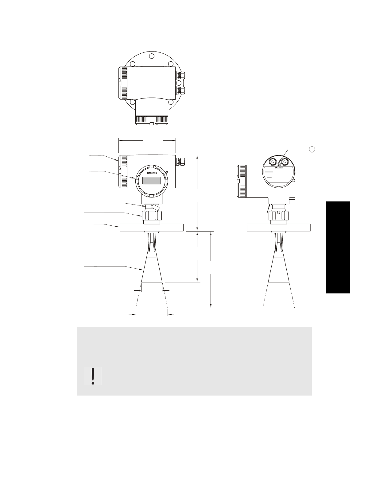
Dimensions
SITRANS LR400 (7ML5421 version) (without Temperature Extension)
connection
cover
electronics
cover
intermediate
flange
threaded
ring
process
flange*
horn
204 mm
(8.0")
SITRANS LR 400
74 mm
(2.9")
93 mm
(3.7")
earth
terminal
257 mm
(10.1")**
Specifications
mmmmm
191 mm
(7.5")
238 mm
(9.4")
Note: Process temperature and pressure capabilities are dependent upon
information on the process device tag. See Appendix IV (Process Pressure/
Temperature de-Rating). Reference drawing listed on the tag is available upon
request.
WARNING: The user is responsible for the selection of bolting and
gasket materials which will fall within the limits of the flange and its
intended use and which are suitable for the service conditions.
*Flange according to DIN 2527 / ANSI B 16.5 / JIS B2238 bolt hole pattern
**An optional purging system can be installed between the flange and the horn antenna.
See page 13 for Air Purging information.
7ML19985FH06 SITRANS LR400 (7ML5421) – INSTRUCTION MANUAL Page 9
SITRANS LR400 (7ML5421 version) with optional Temperature Extension
204 mm
(8.0")
connection
cover
electronics
cover
SITRANS LR 400
intermediate
flange
threaded
ring
process
flange*
384 mm
(15.1")
191 mm
(7.5")
horn
mmmmm
74 mm
Specifications
(2.9")
93 mm
(3.7")
238 mm
(9.4")
*Flange according to DIN 2527 / ANSI B 16.5 / JIS B2238 bolt hole pattern
Note: Process temperature and pressure capabilities are dependent upon
information on the process device tag. See Appendix IV (Process Pressure/
Temperature de-Rating). Reference drawing listed on the tag is available upon
request.
WARNING: The user is responsible for the selection of bolting and
gasket materials which will fall within the limits of the flange and its
intended use and which are suitable for the service conditions.
Page 10 SITRANS LR400 (7ML5421) – INSTRUCTION MANUAL 7ML19985FH06
DIN / JIS Flat Face Flange Diagram (7ML5421 version only)
bolt hole Ø
horn mounting holes
thickness (s)
bolt hole circle Ø
flange O.D.
Flange according to DIN 2527 (see Flange Diagram above)
Pipe Size
Flange
Size
Flange
O.D.
Thickness
(s)
Bolt Hole
Circle Ø
Bolt Hole ØNumber of
80 mm PN 16 200 mm 20.0 mm 160 mm 18.0 mm 8
100 mm PN16 220 mm 20.0 mm 180 mm 18.0 mm 8
150 mm PN 16 285 mm 22.0 mm 240 mm 22.0 mm 8
80 mm PN 40 200 mm 24.0 mm 160 mm 18.0 mm 8
100 mm PN 40 235 mm 24.0 mm 190 mm 22.0 mm 8
150 mm PN 40 300 mm 28.0 mm 250 mm 26.0 mm 8
Flange according to JIS B 2238
Pipe Size
Flange
Size
Flange
O.D.
Thickness
(s)
Bolt Hole
Circle Ø
Bolt Hole Ø
80 mm 10 K 185 mm 20.0 mm 150 mm 19.0 mm 8
100 mm 10 K 210 mm 22.0 mm 175 mm 19.0 mm 8
150 mm 10 k 280 mm 24.0 mm 240 mm 23.0 mm 8
Note: Process temperature and pressure capabilities are dependent upon
information on the process device tag. See Appendix IV (Process Pressure/
Temperature de-Rating). Reference drawing listed on the tag is available upon
request.
WARNING: The user is responsible for the selection of bolting and
gasket materials which will fall within the limits of the flange and its
intended use and which are suitable for the service conditions.
Specifications
Bolts
mmmmm
Number of
Bolts
7ML19985FH06 SITRANS LR400 (7ML5421) – INSTRUCTION MANUAL Page 11
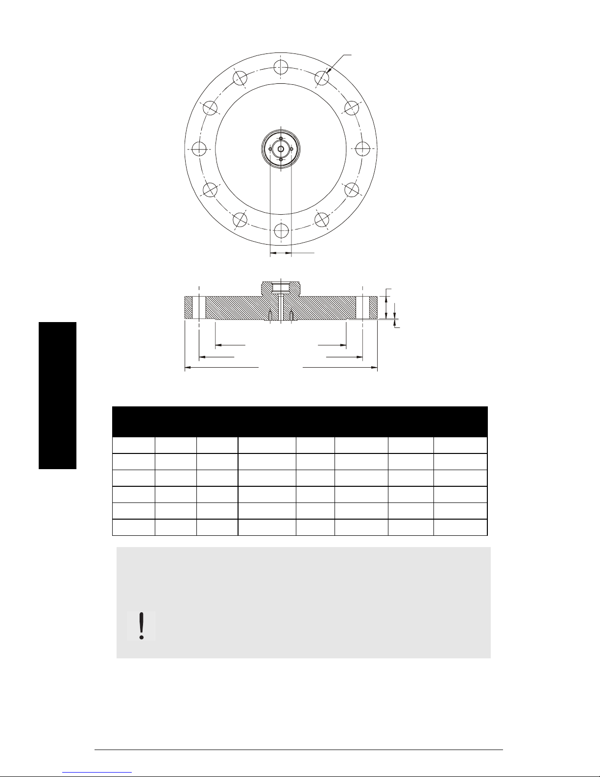
ANSI Raised Face Flange Diagram (7ML5421 version only)
bolt hole Ø
horn mounting holes
thickness (s)
raised face thickness
face O.D.
bolt hole circle Ø
flange O.D.
mmmmm
Flange according to ANSI B 16.5 (see Flange Diagram above)
Specifications
Pipe
Size
Flange
Size
Flange
O.D.
Thickness
(s)
Face
O.D.
Bolt Hole
Circle Ø
0.063" (mm)
Bolt
Hole Ø
Number
of Bolts
3" 150 # 7.50" 0.941" 5.0" 6.00" 0.75" 4
4" 150 # 9.00" 0.941" 6.19" 7.50" 075" 8
6" 150 # 11.00" 1.00" 8.5" 9.50" 0.88" 8
3" 300 # 8.25" 1.12" 5.0" 6.62 0.88" 8
4" 300 # 10.00" 1.25" 6.19" 7.88" 0.88" 8
6" 300 # 12.51" 1.44" 8.5" 10.62" 0.88" 12
Note: Process temperature and pressure capabilities are dependent upon
information on the process device tag. See Appendix IV (Process Pressure/
Temperature de-Rating). Reference drawing listed on the tag is available upon
request.
WARNING: The user is responsible for the selection of bolting and
gasket materials which will fall within the limits of the flange and its
intended use and which are suitable for the service conditions.
Page 12 SITRANS LR400 (7ML5421) – INSTRUCTION MANUAL 7ML19985FH06

Air Purging System (Optional)
For more frequent cleaning, a purging system can be installed between the flange and the
horn antenna. The system provides an 1/8" inlet (female thread) on the flange where
cooling air or cleaning fluid passes through the flange and exits the inside of the horn to
clean it. The customer will supply the purging medium by manual or automatic valve
system. This option is only available with universal flange for purging shown on page 14.
Notes:
• The Air Purge feature should not be activated with a dust cap in place.
• Purge duration, pressure, and interval, will vary with each application. It is the user’s
responsibility to determine the requirements depending on the application and
cleaning required.
• Short duration bursts of high pressure provide more effective cleaning than
continuous low pressure air.
• Some dust particles are highly abrasive and can be drawn into the inside of the horn
during purge cleaning, damaging the internal PTFE emitter of the antenna. A
replacement kit is available from your local Siemens Milltronics representative.
• It is the customer’s responsibility to ensure that any vacuum or pressure in the
measured vessel is maintained, considering the hole that passes through the
process connection and SITRANS LR400 antenna system.
Air Consumption
(Flowrate versus applied pressure)
Air Pressure Approximate inlet volume flow rate (standard cubic feet/minute)
20 5 SCFM
40 6 SCFM
60 8 SCFM
80 9 SCFM
90 10 SCFM
Specifications
mmmmm
7ML19985FH06 SITRANS LR400 (7ML5421) – INSTRUCTION MANUAL Page 13
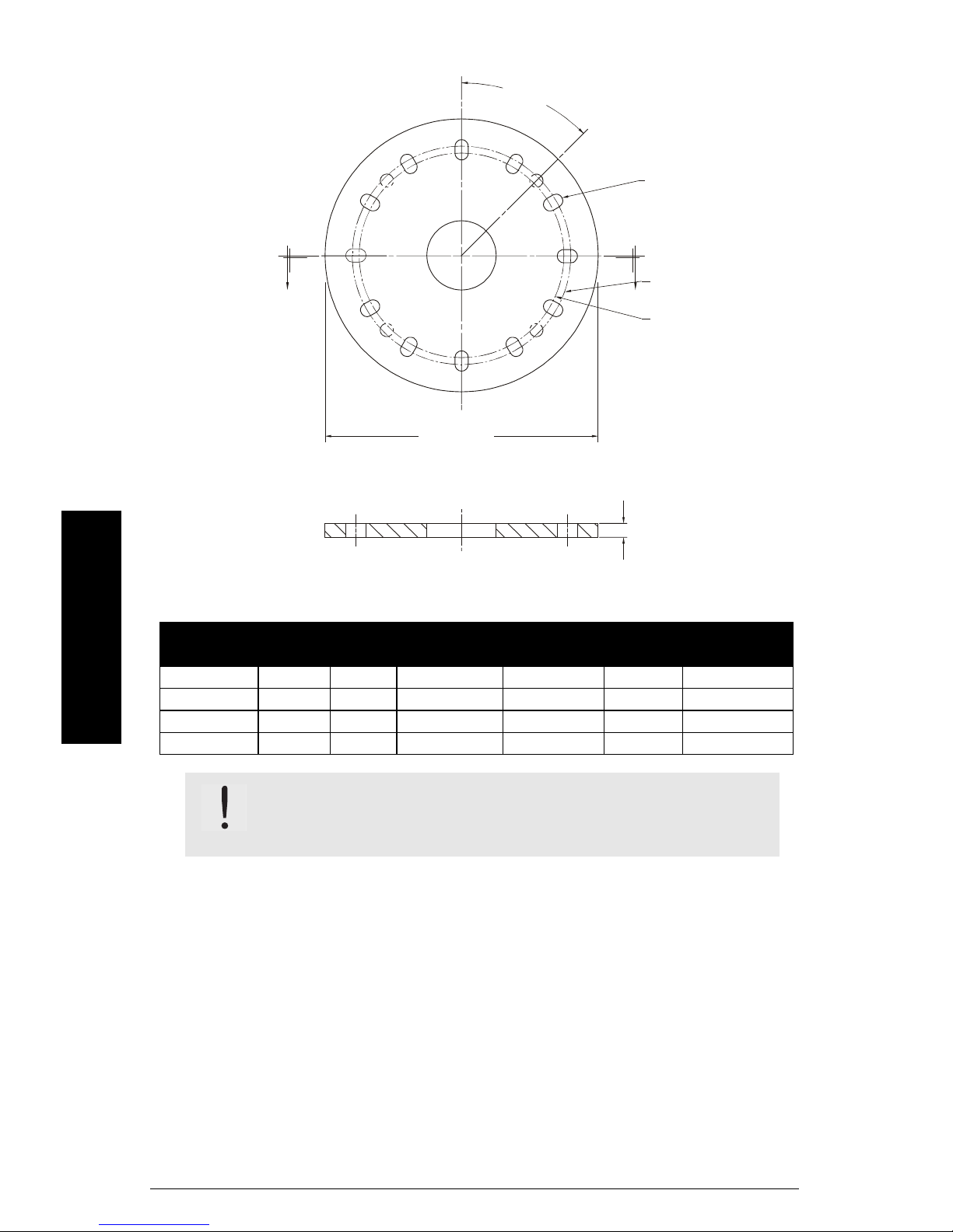
Universal Slotted Flange Diagram (for use with Air Purging Option only)
45°
number of
slotted bolt
holes
A
flange O.D.
section A-A
A
bolt hole
circle max Ø
bolt hole
circle min Ø
thickness
Flange according to Universal Slotted Flange (see Flange Diagram above)
mmmmm
Pipe
Size
Specifications
3" or 80 mm 7.87" 0.40" 6.30" 5.90" 0.38" 8
Flange
O.D.
Thick-
ness (s)
Bolt Hole
Circle Max Ø
Bolt Hole
Circle Min Ø
Bolt Hole
radius
Number of
Slotted Holes
4" or 100 mm 9.00" 0.40" 7.50" 6.89" 0.38" 8
6" or 150 mm 11.22" 0.40" 9.50" 9.44" 0.45" 8
8" or 200 mm 13.5" 0.40" 11.75" 11.4" 0.45" 12
WARNING: The user is responsible for the selection of bolting and
gasket materials which will fall within the limits of the flange and its
intended use and which are suitable for the service conditions.
Page 14 SITRANS LR400 (7ML5421) – INSTRUCTION MANUAL 7ML19985FH06
Installation
Notes:
• SITRANS LR400 is rated for Type 4X/NEMA 4X, Type 6/NEMA 6, IP67.
Follow all installation and operating instructions to meet the
requirements of this type of protection. Use only approved, suitable
sized hubs for watertight applications.
• Observe all maximum permissible ambient and process temperatures.
Refer to Appendix III (Ambient/Operating Temperature Specification).
Provide a warning sign and/or touch guard if the surface of the
measuring instrument can become hotter than 70 °C (158 °F) in use.
WARNINGS:
• This product is designated as a Pressure Accessory per directive
97/23/EC and is not
• Improper installation may result in loss of process pressure.
Mounting Location
intended for use as a safety device.
Recommendations
• Position device with easy access for viewing display and programming via handheld
programmer.
• Mount device in an environment suitable to the housing rating and the materials of
construction.
• Mount the unit more than 1 m away from the vessel walls, pipes and other
assemblies as well as the filling stream, because all these influences will become
noticeable as reflective interference. Align the antenna so that the radar cone
intersects the surface of the measuring medium as vertically as possible.
Precautions
• Do not mount in direct sunlight without the use of a sun shield.
ambient temperature
65 °C (149 °F) max.
Warning: Internal temperature
internal enclosure
temperature
must not exceed 85 °C (185 °F)!
flange
temperature
hand
programmer
Installation
mmmmm
• Avoid proximity to high voltage or current wiring, high voltage or current contacts,
and to variable frequency motor speed controllers.
• Avoid interference to emission cone from obstructions or from fill path.
• Avoid central locations on vesse
7ML19985FH06 SITRANS LR400 (7ML5421) – INSTRUCTION MANUAL Page 15
process temperature
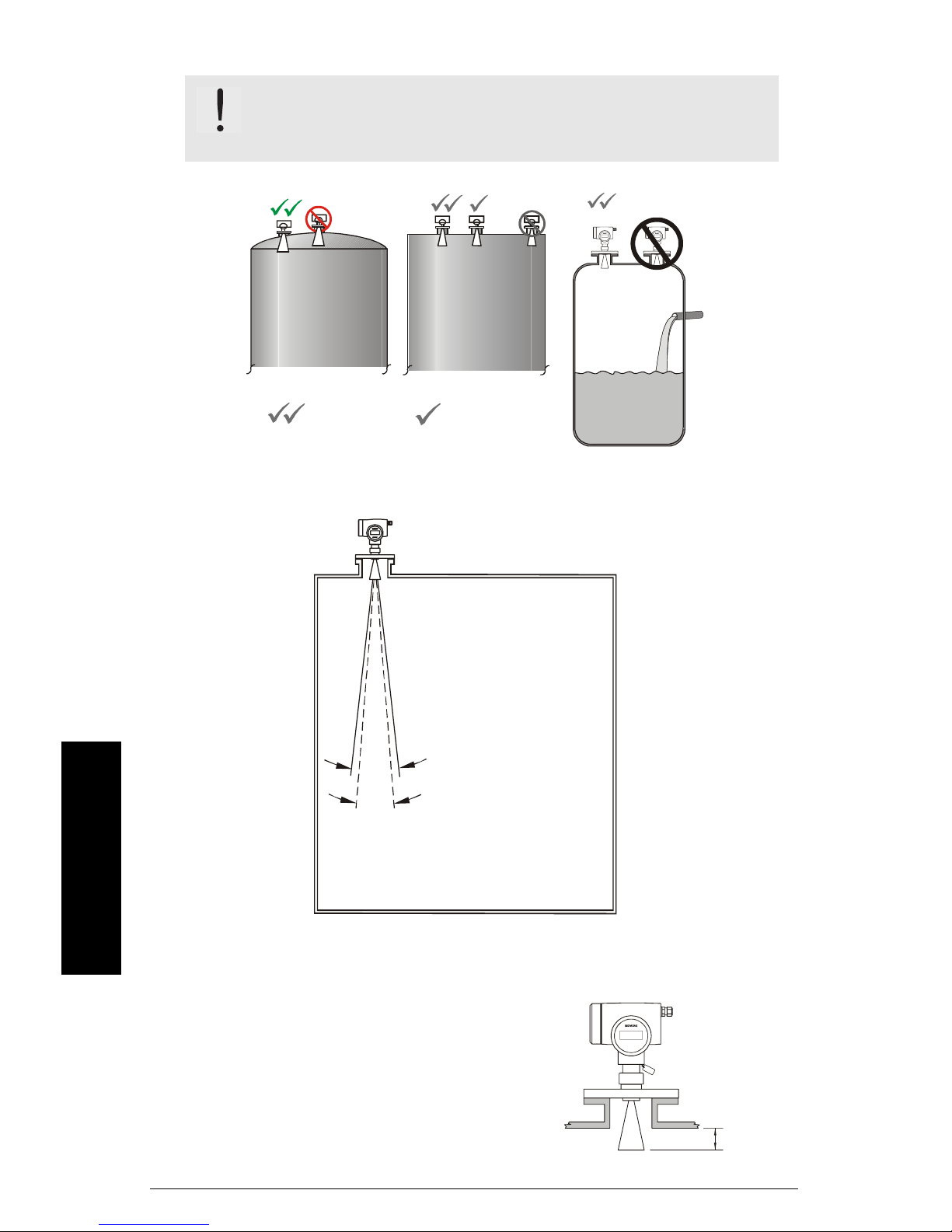
WARNING: For vessels with conical or parabolic tops, avoid
mounting the unit at the center.
echoes into the centre, giving false readings.
The concavity of the top can focus
Parabolic or Conical
Beam Width
P a ra b o lic
is preferred
location
Flat
Flat
is acceptable
location
Keep the emission cone
(9° or 13° depending on
configuration), free of
obstructions.
SITRANS LR 400 SITRANS LR 400
mmmmm
Installation
Correct Installation in Mounting Nozzle
The bottom edge of the antenna must project
into the vessel to avoid reflective interference
at the wall of the nozzle. Above flange size
DN 150/6", the antenna need not project beyond
the nozzle unless the radiation cone (the
extension of the antenna’s angle) touches the
nozzle wall.
Page 16 SITRANS LR400 (7ML5421) – INSTRUCTION MANUAL 7ML19985FH06
13°
short horn antenna
long horn antenna
9°
SITRANS LR 400
10 mm
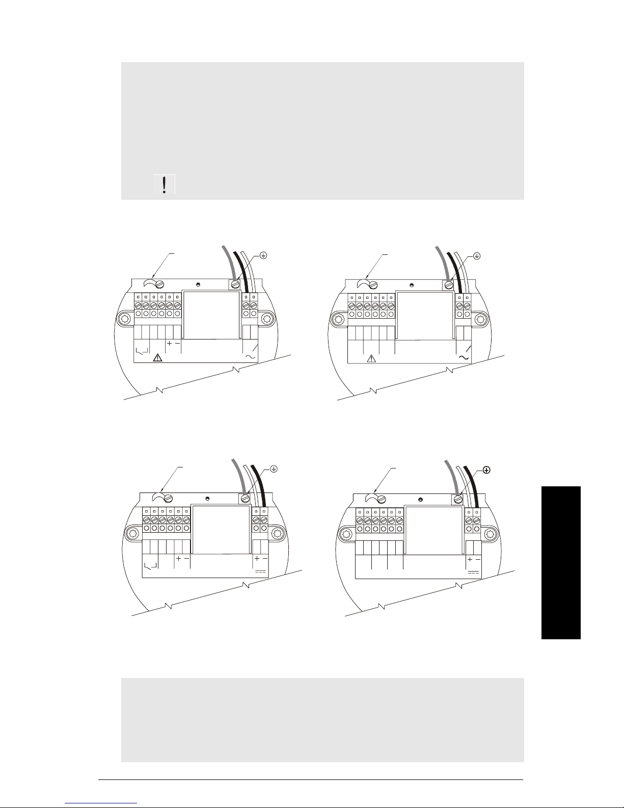
Electrical Connection
Notes:
• The equipment must be protected by a 15A fuse or circuit breaker in the
building installation.
• A circuit breaker or switch in the building installation, marked as the
disconnect switch, shall be in close proximity to the equipment and within
easy reach of the operator.
WARNING:
All field wiring must have insulation suitable for at least 250 V.
AC version:
HART wiring
cable clamp
earth
terminal
PROFIBUS wiring
cable clamp
earth
terminal
mA
DC version:
HART wiring
Rated temperature of
connection cables must
exceed maximum ambient
temperature by at least 15 K
12645378
L
1L2
N
645378
PROFIBUS PA
Rated temperature of
connection cables must
exceed maximum ambient
temperature by at least 15 K
PROFIBUS wiring
12645378
19- 30 V
earth
terminal
PROFIBUS PA
cable clamp cable clamp
Rated temperature of
connection cables must
mA
exceed maximum ambient
temperature by at least 15 K
Rated temperat ure of
connection cables must
exceed maximum ambient
temperature by at least 15 K
1
L1L
2
2
N
12645378
19-30 V
earth
terminal
Installation
mmmmm
• The DC input terminals shall be supplied from a source providing electrical isolation
between the input and output, in order to meet the applicable safety requirements of
IEC 61010-1
Notes (AC and DC versions):
• 4-20 mA, PROFIBUS PA, DC input circuits, 14 - 20 AWG, shielded copper
wire
• AC input circuit, min 14 AWG copper wire
• Recommended torque on terminal clamping screws, 0.5 - 0.6 Nm.
7ML19985FH06 SITRANS LR400 (7ML5421) – INSTRUCTION MANUAL Page 17

Connecting the SITRANS LR400:
1. Release the cover lock on the connection box with a 3 mm Allen key.
2. Unscrew the cover from the connection box.
3. Push the power cable and signal cable through the cable gland on the right of the
unit, up to the terminal strip. Lay the cable in a bend before the cable gland so that
moisture cannot enter the connection box.
4. Connect the earth conductor of the power supply to the earth terminal in the
connection box. Adjust the cable length so that the earth conductor would be last to
disconnect last if cable is pulled.
5. In devices with ignition protection types II 1/2G EEx dem [ia] IIC T6 and II 1/2G EEx
dem [ib] IIC T6 or II 2G EEx dem [ia] IIC T6 and II 2G EEx dem [ib] IIC T6 (7ML5421
version), mount the cover for the power supply terminals.
6. Tighten the cable screw gland and check the strain relief (pull and turn).
7. In devices with ignition protection type II 1/2G EEx D IIC T6 or II 2G EEx d IIC T6
(7ML5421 version), replace unused screw-type cable glands with a certified dummy
plug.
8. Screw the cover onto the housing and tighten it without using a tool. The sealing
ring must be clean and undamaged.
9. Mount the cover lock of the connection box cover.
10. Connect the earth terminal located between the screw-type cable glands to a
ground connection at your vessel by using a cable of a cross-section at least
2.5 mm
For error-free communication via the HART protocol, a load of at least 230 Ω must be
available in the signal circuit.
2
.
WARNINGS:
• To avoid short-circuits, do not connect a load resistance with bare wires in
the connection box.
• The housing cover may not be unscrewed in a hazardous area when the
device is under voltage (power supply, digital outputs on external supply).
• In devices with ignition protection types II 1/2G EEx dem [ia] IIC T6 and II 1/
2G EEx dem [ib] IIC T6 II 2G EEx dem [ia] IIC T6 and II 2G EEx dem [ib]
IIC T6 (7ML5421 version), only the cover of the connection box may be
unscrewed for test purposes. The cover on the power supply terminals may
not be removed!
mmmmm
Installation
Page 18 SITRANS LR400 (7ML5421) – INSTRUCTION MANUAL 7ML19985FH06
Start Up
Self-test
When power is supplied, the device performs a self-test. Then, when the multi-display
appears, the device is ready for programming.
Note: Frequent switching off and on of the device causes aging of the electronics
(monitored using Parameter 3.1).
Multi-display
The multi-display shows on the LCD after a successful self-test with the first line showing
level output and the second line showing signal-to-noise ratio (factory setting):
+1 2 300 m
.
bd03+
Local Programming
When the multi-display appears on the LCD, begin local
programming using the hand programmer. To access the
parameter settings, press LEFT once. Main Menu is visible
as the first LCD line. Then program the unit beginning with the
Auto-Setup parameters.
Auto-Setup
After switching on the SITRANS LR400, and after a successful self test, press LEFT to
access the parameters. Set the Auto-Setup parameters to make the system operational:
(see page 27)
• The language of the local user interface
• The unit of length of the measured level
• The nozzle height in the selected unit of length
•The vessel height in the selected unit of length
• The LRV (lower range value) as a distance from the bottom of the vessel
• The URV (upper range value) as a distance from the bottom of the vessel
• The damping of the measured level in seconds
• The application type
• The bus address by PROFIBUS PA communication (on PROFIBUS models)
Enter the necessary values as described in Parameters on page 26.
Note: It is strongly recommended that a Customer Code (Parameter 5.2) be entered
after all programming is completed to secure the programmed values from changes.
If the multi-display does not appear or displays incorrect measured values after AutoSetup, proceed as described in Troubleshooting on page 81.
Refer to the
7ML19985FH06 SITRANS LR400 (7ML5421) – INSTRUCTION MANUAL Page 19
Parameter
Start Up
mmmmm
section that begins on page 26 for a list of available parameters.
Operation
General Information
mmmmm
You can operate SITRANS LR400 with:
Operation
• Handheld infrared programmer
• Handheld HART Communicator
• PC/Laptop and SIMATIC PDM software via HART or PROFIBUS PA
Notes:
• SITRANS LR400 can be operated and programmed easily with SIMATIC
PDM software. This software gives you the added possibility of saving and
archiving your application-specific parameters and copying them back into
the device if necessary.
• It is best to perform the operations described in the following sections
directly on the device to familiarize yourself with the operation.
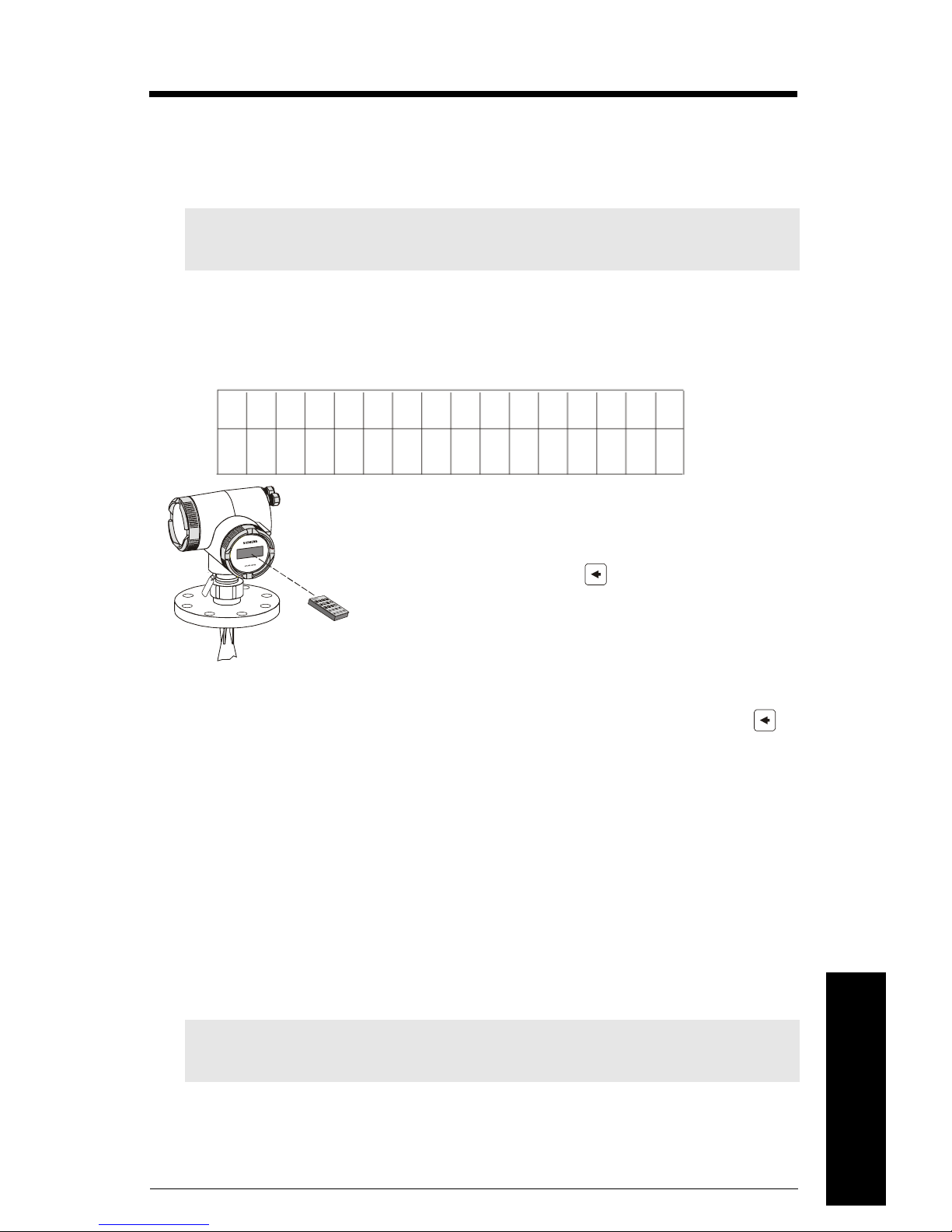
Operating SITRANS LR400
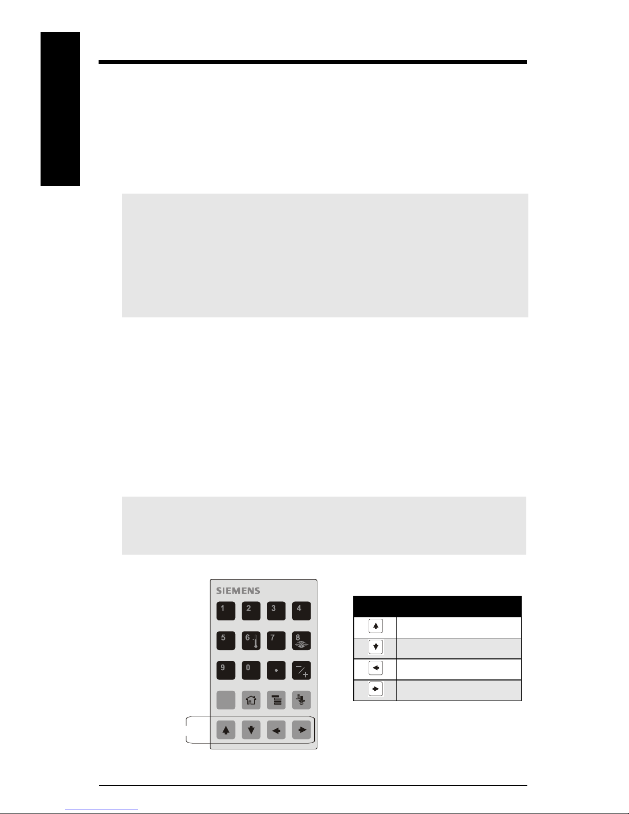
Use the arrow keys at the bottom of the hand programmer to program SITRANS LR400.
The two-line LCD displays the parameters. You can alter the setting or change to other
parameters using the arrows on the hand programmer (see page 22 for information on
navigating the menus using the arrow keys).
Hand Programmer
Note: The ARROW buttons shown below are required for programming
this product. The additional buttons on the hand programmer do not
apply to SITRANS LR400.
SITRANS LR400
buttons
Key Programming Mode
Paramet er scroll UP
Paramet er scroll DOWN
LEFT Arrow (or CANCEL)
RIGHT Arrow (or ENTER)
C
Page 20 SITRANS LR400 (7ML5421) – INSTRUCTION MANUAL 7ML19985FH06
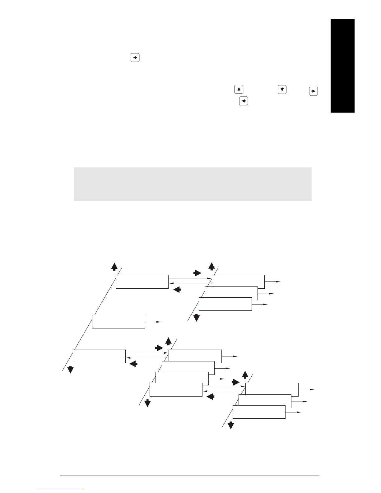
Selecting a Parameter
After a successful self-test, SITRANS LR400 displays the two-line multi-display.
Press LEFT ARROW to access the parameter menus. The first line of the display
shows the current parameter menu level. The second line shows one of the parameters
you can access in the current parameter group.
Scroll through the parameters in the group by pressing UP and DOWN . RIGHT
accesses the parameter displayed on the second line. LEFT closes this parameter
and moves up one level until you return to the multi-display.
When you select a parameter, its current value is displayed in the second line. When the
cursor flashes, programming is enabled, (see Disabling and Enabling Programming on
page 23) and you can change the current setting. If the parameter is display only or if
programming is disabled, the cursor will not flash.
Note: The background illumination of the LCD switches on when the hand
programmer is used for programming. It goes out about three minutes after last
button press.
Structure of Parameters
Operation
mmmmm
Operation is hierarchically structured: the parameters are arranged in groups and
assigned a numerical menu identification (see example below from a HART device).
2. Display
1 Multi-display
2. Display
2 Level
2. Display
3 Volume
O
e
l
g
n
i
t
a
r
e
p
4.4 Digital outpu
1 Function DO
4.4 Digital outpu
3
l
e
2 Error level
v
4.4 Digital outpu
3 Signal type DO
1
l
e
v
e
l
g
n
i
t
Function group
a
r
e
3 Diagnostics
p
O
Function group
4 Device data
Function group
2 Display
g
n
i
t
a
r
e
p
O
4. Device data
2
l
2 Operat. param.
e
v
4. Device data
e
l
3 Analog output
4. Device data
4 Digital output
4. Device data
1 Units
7ML19985FH06 SITRANS LR400 (7ML5421) – INSTRUCTION MANUAL Page 21

mmmmm
Changing a Parameter Value
Selecting a Parameter Value from a List
In many cases, you can assign a parameter a value from a list of options.
Operation
You will see a single entry of the possible choices in the second display line.
• Press UP or DOWN to cycle through the list and choose the desired entry.
Press RIGHT to assign the current entry to the parameter. The device accepts
the new setting, closes the input and returns to the next parameter level up.
• LEFT operates like a CANCEL key: When pressed, the device closes the
parameter input but keeps the originally displayed value. It does not save a changed
setting!
For an example of assigning a value from a selection list, see
Examples
on page 24.
Functions of Hand Programmer Keys
• Changes display from RUN mode to PROGRAM mode
• Operates as a CANCEL key when programming input position is at the far left
• Moves input position to the left during PROGRAM mode
Parameter Operating
• Operates as an ENTER key when input position is at the far right. If the input
value is not within the permissible input range. Then an error message is
displayed.
• Moves input position to the right during PROGRAM mode
• Changes input variable up or down
Top or bottom of representable range
If you press UP when the value is at the top of the representable range,
SITRANS LR400 automatically places the value at the next highest position. If 0.9 is
displayed and you press UP , the value becomes 1.0. So, 9 becomes 10, 90 or 99
become 100 (depending on whether you have set the input position to the second or first
9), etc.
This input system also works in the opposite direction: For example, when 100 is
displayed and you press DOWN on the first or second 0, the numeric value changes
to 90 or 99 and the device cancels the places in front of the decimal point.
Decimal point
You can also set the cursor to the decimal point (unless an integer value is currently
displayed). UP or DOWN will then multiply or divide the displayed value by 10. The
necessary additional places in front of the decimal point appear. You cannot change the
number of displayed decimal places.
Page 22 SITRANS LR400 (7ML5421) – INSTRUCTION MANUAL 7ML19985FH06

Display scrolling
Displayed text may be longer than the field of the display. An arrow pointing outward on
the right or left hand side of the display line indicates that the text continues outside the
multi-display. You can read the additional text using RIGHT and LEFT to move the
pointer past the end of the line.
See
Parameter Operating Examples
on page 24 for an example of manual input.
Disabling and Enabling Programming
To prevent unauthorized personnel causing programming errors using the display
module, set a customer code – a personal, number code up to 9 digits. A device protected
by a customer code still displays all functions and values but it requests input of the code
before resetting a parameter.
Note: The customer code is activated 10 minutes after you have programmed
Parameter 5.2 Customer Code.
Programming is enabled when you:
Operation
mmmmm
• enter the requested customer code for the current parameter
or
• release the programming lock using Parameter 5.1 Code Input on page 56.
The programming lock will be released for approximately 10 minutes. Any other code
number locks and disables programming.
When you return to the multi-display or enter a number in the Code Input parameter
which is different from the customer code, or do not operate the device for 10 minutes,
the programming lock is enabled.
Note: If Customer Code (Parameter 5.2) is 0, programming of parameters is always
enabled. We strongly recommend that a customer code be entered after all
programming is completed to secure the programmed values from change.
7ML19985FH06 SITRANS LR400 (7ML5421) – INSTRUCTION MANUAL Page 23
mmmmm
Parameter Operating Examples
Example (HART): Change the length unit from m to mm.
The example begins at the multi-display (1). Follow the bold arrowed path to complete the
task. Use the arrow buttons shown next to the numbered operation steps.
Operation
Function group
1 Auto-Setup
Function group
2 Display
Function group
3 Diagnostics
Function group
4 Device data
+12,300 m
+30 dB
4. Device data
1 Units
4. Device data
2. Operat. param.
4. Device data
3 Analog output
4.1 Units
1 Length Unit
4.3 Analog output
1 Error level
4.3 Analog output
2 AO select
4.1.1 Length unit
m
4.1.1 Length unit
cm
4.3.1 Error level
D: Error signal
4.3.2 AO select
1 Level
Page 24 SITRANS LR400 (7ML5421) – INSTRUCTION MANUAL 7ML19985FH06
Example 2: Change the filling speed from 2.0 cm/min to 100 cm/min.
Access the Fill speed parameter from the multi-display according to instructions on
page 22.
Operation
mmmmm
The default setting appears in the display.
Enable the programming by pressing RIGHT
. The second segment of the second
display line flashes.
Set the digit to 1 with DOWN .
Select the decimal point with RIGHT .
Press UP twice so that two other places
appear in front of the decimal point.
4.2.2.5.
+
2.00
4.2.2.5.
+
2.00
4.2.2.5.
+
1.00
4.2.2.5.
+
1.00
4.2.2.5.
+
100.00
Filling
cm/min
1x
Filling
cm/min
1x
Filling
cm/min
1x
Filling
cm/min
2x
Filling
cm/min
spe
spe
spe
spe
spe
Select the last decimal place with RIGHT .
End the input with RIGHT (ENTER).
4.2.2.5.
+
100.00
4.2.2.
Filling speed
5
Filling
Measur. cond
2x
spe
cm/min
1x
7ML19985FH06 SITRANS LR400 (7ML5421) – INSTRUCTION MANUAL Page 25

Parameters (HART)
The parameter groups are followed by the parameters within each group. The parameter
tables show the values you need to enter and are followed by additional information
when necessary. Factory settings are displayed after the parameter name, where
applicable.
Note: Parameter menus are dependent on selections made by the user.
In some cases, parameter menus are renumbered according to the
selection made at the previous menu level. See table below for an
example.
mmmmm
Parameters (HART)
When User chooses Parameter 4.2.2.1:
Application Type = Liquids (Process)
2: Surface
4.2.2.
4.2.2.3: Dead band 4.2.2.2: Dead band
4: Correction Factor 4.2.2.3: Correction Factor
4.2.2.
4.2.2.5: Filling Speed
6: Reflectivity
4.2.2.
4.2.2.7: Failsafe Level 4.2.2.4: Failsafe Level
4.2.2.8: Failsafe Timer 4.2.2.5: Failsafe Timer
9: Range Extension 4.2.2.6: Range Extension
4.2.2.
Default values are indicated as "F=" following the parameter number and name.
When User chooses Parameter 4.2.2.1:
Application Type = User tank1
(not available when 4.2.2.1 = User tank1)
(not available when 4.2.2.1 = User tank1)
(not available when 4.2.2.1 = User tank1)
Page 26 SITRANS LR400 (7ML5421) – INSTRUCTION MANUAL 7ML19985FH06
 Loading...