

Siemens SITRANS LR250 PROFIBUS PA Operating Instructions Manual
Radar Transmitters
SITRANS LR250 (PROFIBUS PA)
Operating Instructions 01/2014
SITRANS

Safety Guidelines
Warning notices must be observed to ensure personal safety as well as that of others, and to protect the product and the connected equipment.
These warning notices are accompanied by a clarification of the level of caution to be observed.
Qualified Personnel
This device/system may only be set up and operated in conjunction with this manual. Qualified personnel are only authorized to install and
operate this equipment in accordance with established safety practices and standards.
Unit Repair and Excluded Liability:
The user is responsible for all changes and repairs made to the device by the user or the user’s agent.
All new components are to be provided by Siemens Milltronics Process Instruments.
Restrict repair to faulty components only.
Do not reuse faulty components.
Warning: Cardboard shipping package provides limited humidity and moisture protection. This product can only function properly and safely if
it is correctly transported, stored, installed, set up, operated, and maintained.
This product is intended for use in industrial areas. Operation of this equipment in a residential area may cause interference to several
frequency based communications.
Note: Always use product in accordance with specifications.
Copyright Siemens AG 2013. All Rights Reserved Disclaimer of Liability
This document is available in bound version and in
electronic version. We encourage users to purchase
authorized bound manuals, or to view electronic versions as
designed and authored by Siemens Milltronics Process
Instruments. Siemens Milltronics Process Instruments will
not be responsible for the contents of partial or whole
reproductions of either bound or electronic versions.
MILLTRONICS®is a registered trademark of Siemens Milltronics Process Instruments.
While we have verified the contents of this
manual for agreement with the instrumentation
described, variations remain possible. Thus we
cannot guarantee full agreement. The contents of
this manual are regularly reviewed and
corrections are included in subsequent editions.
We welcome all suggestions for improvement.
Technical data subject to change.
Contact SMPI Technical Publications European Authorized Representative
at the following address:
Technical Publications Siemens AG
Siemens AG Industry Sector
Siemens Milltronics Process Instruments 76181 Karlsruhe
1954 Technology Drive, P.O. Box 4225 Deutschland
Peterborough, Ontario, Canada, K9J 7B1
Email: techpubs.smpi@siemens.com
For a selection of Siemens Milltronics level measurement manuals, go to:
www. siemens.com/processautomation. Under Process Instrumentation, select
listed under the product family.
Level Measurement
and then go to the manual archive
For a selection of Siemens Milltronics weighing manuals, go to:
www. siemens.com/processautomation. Under Weighing Technology, select
archive listed under the product family.
Continuous Weighing Systems
and then go to the manual
© Siemens AG 2013

SITRANS LR250 (PROFIBUS PA)
___________________
___________________
___________________
___________________
___________________
___________________
___________________
___________________
___________________
___________________
___________________
___________________
___________________
___________________
___________________
___________________
___________________
SITRANS
Radar Transmitters
SITRANS LR250 (PROFIBUS PA)
Operating Instructions
01/2014
A5E32221386
Introduction
1
Safety notes
2
Description
3
Installing/mounting
4
Connecting
5
Commissioning
6
Remote operation
7
Parameter reference
8
Service and maintenance
9
Diagnosing and
troubleshooting
10
Technical data
11
Dimension drawings
12
Appendix A: Technical
reference
A
Appendix B: PROFIBUS PA
profile structure
B
Appendix C:
Communications via
PROFIBUS
C
Appendix D: Certificates and
Support
D
List of abbreviations
13
LCD menu structure
14
-AB

Siemens AG
Industry Sector
Postfach 48 48
90026 NÜRNBERG
GERMANY
Order number: A5E32221386
Ⓟ
Copyright © Siemens AG 2013.
All rights reserved
Warning notice system
DANGER
indicates that death or severe personal injury will result if proper precautions are not taken.
WARNING
indicates that death or severe personal injury may result if proper precautions are not taken.
CAUTION
indicates that minor personal injury can result if proper precautions are not taken.
NOTICE
indicates that property damage can result if proper precautions are not taken.
Qualified Personnel
personnel qualified
Proper use of Siemens products
WARNING
Siemens products may only be used for the applications described in the catalog and in the relevant technical
maintenance are required to ensure that the products operate safely and without any problems. The permissible
ambient conditions must be complied with. The information in the relevant documentation must be observed.
Trademarks
Disclaimer of Liability
Legal information
This manual contains notices you have to observe in order to ensure your personal safety, as well as to prevent
damage to property. The notices referring to your personal safety are highlighted in the manual by a safety alert
symbol, notices referring only to property damage have no safety alert symbol. These notices shown below are
graded according to the degree of danger.
If more than one degree of danger is present, the warning notice representing the highest degree of danger will be
used. A notice warning of injury to persons with a safety alert symbol may also include a warning relating to property
damage.
The product/system described in this documentation may be operated only by
in accordance with the relevant documentation, in particular its warning notices and safety instructions. Qualified
personnel are those who, based on their training and experience, are capable of identifying risks and avoiding
potential hazards when working with these products/systems.
for the specific task
Note the following:
documentation. If products and components from other manufacturers are used, these must be recommended
or approved by Siemens. Proper transport, storage, installation, assembly, commissioning, operation and
All names identified by ® are registered trademarks of Siemens AG. The remaining trademarks in this publication may
be trademarks whose use by third parties for their own purposes could violate the rights of the owner.
We have reviewed the contents of this publication to ensure consistency with the hardware and software described.
Since variance cannot be precluded entirely, we cannot guarantee full consistency. However, the information in this
publication is reviewed regularly and any necessary corrections are included in subsequent editions.
09/2013 Technical data subject to change

Table of contents
1 Introduction ............................................................................................................................................. 9
2 Safety notes .......................................................................................................................................... 11
3 Description ............................................................................................................................................ 13
4 Installing/mounting ................................................................................................................................ 15
5 Connecting ........................................................................................................................................... 25
1.1 The manual .................................................................................................................................... 9
1.2 Firmware revision history ............................................................................................................. 10
2.1 Safety marking symbols ............................................................................................................... 11
2.2 FCC Conformity ........................................................................................................................... 11
2.3 CE Electromagnetic Compatibility (EMC) Conformity.................................................................. 12
3.1 SITRANS LR250 overview ........................................................................................................... 13
3.2 Programming ................................................................................................................................ 14
3.3 Applications .................................................................................................................................. 14
3.4 Approvals and certificates ............................................................................................................ 14
4.1 Pressure applications ................................................................................................................... 16
4.1.1 Pressure Equipment Directive, PED, 97/23/EC ........................................................................... 16
4.2 Mounting location ......................................................................................................................... 16
4.2.1 Nozzle design ............................................................................................................................... 17
4.2.2 Nozzle location ............................................................................................................................. 17
4.2.3 Orientation in a vessel with obstructions ..................................................................................... 20
4.2.4 Mounting on a Stillpipe or Bypass Pipe ....................................................................................... 20
4.2.5 Stillpipe or Bypass Pipe requirements ......................................................................................... 21
4.2.6 Device orientation ........................................................................................................................ 21
4.3 Installation instructions ................................................................................................................. 22
4.4 Flange bolting, Flanged encapsulated antenna only ................................................................... 22
5.1 Power ........................................................................................................................................... 25
5.2 Connecting SITRANS LR250 ....................................................................................................... 26
5.2.1 Basic PLC configuration with PROFIBUS PA .............................................................................. 28
5.3 Wiring setups for hazardous area installations ............................................................................ 28
5.3.1 PLC configuration with PROFIBUS PA for hazardous areas ...................................................... 29
5.3.2 Intrinsically safe wiring ................................................................................................................. 30
5.3.3 Non-sparking wiring ..................................................................................................................... 33
SITRANS LR250 (PROFIBUS PA)
Operating Instructions, 01/2014, A5E32221386-AB
3

Table of contents
6 Commissioning ..................................................................................................................................... 35
7 Remote operation ................................................................................................................................. 59
5.3.4 Non-incendive wiring (US/Canada only) ..................................................................................... 33
5.4 Instructions specific to hazardous area installations ................................................................... 34
6.1 Operating via the handheld programmer .................................................................................... 35
6.1.1 Power up ..................................................................................................................................... 35
6.1.2 Handheld programmer functions ................................................................................................. 35
6.1.2.1 The LCD display .......................................................................................................................... 36
6.1.2.2 Handheld programmer (Part No. 7ML1930-1BK) ....................................................................... 38
6.1.3 Programming ............................................................................................................................... 39
6.1.3.1 Enter program mode ................................................................................................................... 40
6.1.3.2 Navigating: key functions in navigation mode ............................................................................. 41
6.1.3.3 Editing in program mode ............................................................................................................. 42
6.1.3.4 Quick Start Wizard via the handheld programmer ...................................................................... 45
6.1.3.5 Auto False Echo Suppression ..................................................................................................... 47
6.1.3.6 Requesting an Echo Profile......................................................................................................... 48
6.1.3.7 Device address ........................................................................................................................... 49
6.2 Application examples .................................................................................................................. 50
6.2.1 Liquid resin in storage vessel, level measurement ..................................................................... 51
6.2.2 Horizontal vessel with volume measurement .............................................................................. 53
6.2.3 Application with stillpipe .............................................................................................................. 55
7.1 Operating via SIMATIC PDM ...................................................................................................... 59
7.1.1 Functions in SIMATIC PDM ........................................................................................................ 59
7.1.1.1 Features of SIMATIC PDM Rev. 6.0, SP4 or higher ................................................................... 60
7.1.1.2 Features of SIMATIC PDM Rev. 5.2, SP1 .................................................................................. 60
7.1.1.3 SIMATIC PDM Version ............................................................................................................... 60
7.1.2 Electronic Device Description (EDD) .......................................................................................... 61
7.1.2.1 Updating the Electronic Device Description (EDD) ..................................................................... 61
7.1.2.2 Configuring a new device ............................................................................................................ 61
7.1.3 Quick start wizard via SIMATIC PDM ......................................................................................... 62
7.1.4 Changing parameter settings using SIMATIC PDM ................................................................... 68
7.1.5 Parameters accessed via pull-down menus ............................................................................... 69
7.1.5.1 Echo profile utilities ..................................................................................................................... 69
7.1.5.2 Auto false echo suppression ....................................................................................................... 73
7.1.5.3 Echo setup .................................................................................................................................. 76
7.1.5.4 Maintenance ................................................................................................................................ 77
7.1.5.5 Acknowledge Faults .................................................................................................................... 78
7.1.5.6 Wear ............................................................................................................................................ 78
7.1.5.7 Simulation.................................................................................................................................... 79
7.1.5.8 Write locking ................................................................................................................................ 81
7.1.5.9 Master reset ................................................................................................................................ 82
7.1.5.10 Factory defaults ........................................................................................................................... 82
7.1.5.11 Diagnostics .................................................................................................................................. 83
7.2 Operating via FDT ....................................................................................................................... 90
SITRANS LR250 (PROFIBUS PA)
4 Operating Instructions, 01/2014, A5E32221386-AB

Table of contents
8 Parameter reference ............................................................................................................................. 93
9 Service and maintenance .................................................................................................................... 159
10 Diagnosing and troubleshooting .......................................................................................................... 161
11 Technical data .................................................................................................................................... 169
12 Dimension drawings ............................................................................................................................ 177
7.2.1 Device Type Manager (DTM) ....................................................................................................... 90
7.2.2 SITRANS DTM ............................................................................................................................. 90
7.2.3 The device EDD ........................................................................................................................... 91
7.2.4 Configuring a new device via FDT ............................................................................................... 91
8.1 Alphabetical parameter list ......................................................................................................... 155
9.1 Maintenance ............................................................................................................................... 159
9.2 Unit repair and excluded liability ................................................................................................ 159
9.3 Part replacement ........................................................................................................................ 159
10.1 Device status icons .................................................................................................................... 162
10.2 General fault codes .................................................................................................................... 163
10.3 Operation troubleshooting .......................................................................................................... 166
11.1 Power ......................................................................................................................................... 169
11.2 Performance ............................................................................................................................... 170
11.3 Interface ..................................................................................................................................... 171
11.4 Mechanical ................................................................................................................................. 171
11.5 Environmental ............................................................................................................................ 173
11.6 Process ...................................................................................................................................... 173
11.7 Approvals ................................................................................................................................... 174
11.8 Programmer (infrared keypad) ................................................................................................... 175
12.1 Threaded horn antenna ............................................................................................................. 177
12.2 Threaded horn antenna with extension ..................................................................................... 180
12.3 Flanged horn antenna ................................................................................................................ 182
12.4 Flanged horn antenna with extension ........................................................................................ 184
12.5 Flanged encapsulated antenna (2"/DN50/50A sizes only) ........................................................ 186
12.6 Flanged encapsulated antenna (3"/DN80/80A sizes and larger) ............................................... 188
12.7 Threaded PVDF antenna ........................................................................................................... 190
12.8 Threaded connection markings .................................................................................................. 191
12.9 Raised-Face flange per EN 1092-1 for flanged horn antenna ................................................... 192
SITRANS LR250 (PROFIBUS PA)
Operating Instructions, 01/2014, A5E32221386-AB
5

Table of contents
A Appendix A: Technical reference .......................................................................................................... 201
B Appendix B: PROFIBUS PA profile structure ........................................................................................ 221
C Appendix C: Communications via PROFIBUS ...................................................................................... 229
12.10 Raised-Face flange per EN 1092-1 for flanged encapsulated antenna .................................... 194
12.11 Flat-Face flange ........................................................................................................................ 197
12.12 Process connection tag (pressure rated versions).................................................................... 200
A.1 Principles of operation ............................................................................................................... 201
A.2 Echo processing ........................................................................................................................ 202
A.2.1 Process Intelligence .................................................................................................................. 202
A.2.2 Echo Selection .......................................................................................................................... 203
A.2.3 CLEF Range ............................................................................................................................. 206
A.2.4 Echo Threshold ......................................................................................................................... 206
A.2.5 Echo Lock.................................................................................................................................. 206
A.2.6 Auto False Echo Suppression ................................................................................................... 207
A.2.7 Measurement Range ................................................................................................................. 209
A.2.8 Measurement Response ........................................................................................................... 209
A.2.9 Damping .................................................................................................................................... 210
A.2.10 Loss of Echo (LOE) ................................................................................................................... 210
A.2.10.1 LOE Timer ................................................................................................................................. 210
A.2.10.2 Fail-safe Behavior ..................................................................................................................... 211
A.3 Maximum Process Temperature Chart ..................................................................................... 212
A.4 Process Pressure/Temperature Derating Curves ..................................................................... 213
A.4.1 Horn antenna ............................................................................................................................ 214
A.4.2 Flanged horn antenna ............................................................................................................... 215
A.4.3 Flanged encapsulated antenna ................................................................................................. 218
A.4.4 PVDF antenna ........................................................................................................................... 220
B.1 PROFIBUS Level Device Design .............................................................................................. 221
B.2 Block Model ............................................................................................................................... 221
B.2.1 Description of the blocks ........................................................................................................... 222
B.2.1.1 Transducer Block function groups ............................................................................................ 222
B.2.1.2 How the transducer block works: .............................................................................................. 223
B.2.1.3 Analog Input Function Blocks 1 and 2 ...................................................................................... 225
C.1 Device configuration .................................................................................................................. 229
C.1.1 SIMATIC PDM ........................................................................................................................... 229
C.1.1.1 Electronic Device Description ................................................................................................... 229
C.2 Network configuration ............................................................................................................... 230
C.2.1 The GSD file .............................................................................................................................. 230
C.3 Bus termination ......................................................................................................................... 230
C.4 Power demands ........................................................................................................................ 230
C.5 PROFIBUS address .................................................................................................................. 231
SITRANS LR250 (PROFIBUS PA)
6 Operating Instructions, 01/2014, A5E32221386-AB

Table of contents
D Appendix D: Certificates and Support .................................................................................................. 245
13 List of abbreviations ............................................................................................................................ 247
14 LCD menu structure ............................................................................................................................ 249
Glossary ............................................................................................................................................. 255
Index................................................................................................................................................... 261
C.6 Operating as a profile device ..................................................................................................... 232
C.6.1 Configuring a new device ........................................................................................................... 232
C.6.2 Configuring PROFIBUS PA with an S7-300/ 400 PLC .............................................................. 232
C.7 Cyclic versus acyclic data .......................................................................................................... 233
C.7.1 Cyclic data .................................................................................................................................. 233
C.8 Status byte ................................................................................................................................. 234
C.9 Condensed status ...................................................................................................................... 235
C.10 Diagnostics ................................................................................................................................. 237
C.10.1 Diagnosis reply (available cyclically).......................................................................................... 237
C.10.2 Diagnosis object (available cyclically or acyclically) .................................................................. 237
C.10.3 Extended mode diagnosis .......................................................................................................... 238
C.10.4 Condensed mode diagnosis ...................................................................................................... 239
C.10.5 Acyclic extended diagnostics (general fault codes) ................................................................... 240
C.10.6 Acyclic data ................................................................................................................................ 244
D.1 Certificates ................................................................................................................................. 245
D.2 Technical support ....................................................................................................................... 245
SITRANS LR250 (PROFIBUS PA)
Operating Instructions, 01/2014, A5E32221386-AB
7

Table of contents
SITRANS LR250 (PROFIBUS PA)
8 Operating Instructions, 01/2014, A5E32221386-AB

1
1.1
The manual
Note
This manual applies to the SITRANS LR250 (PROFIBUS PA) only.
Application examples
Note
For industrial use only
This product is intended for use in industrial areas. Operation of this equipment in a
residential area may cause interference to several frequency based communications.
This manual will help you set up your radar device for optimum performance. For other Siemens
Milltronics level measurement manuals, go to:
Siemens level (http://www.siemens.com/level
Follow these operating instructions for quick, trouble-free installation, and maximum accuracy
and reliability of your device.
We always welcome suggestions and comments about manual content, design, and
accessibility. Please direct your comments to:
Technical publications (mailto:techpubs.smpi@siemens.com
The application examples used in this manual illustrate typical installations. [See Application
examples (Page 50).] Because there is often a range of ways to approach an application, other
configurations may also apply.
In all examples, substitute your own application details. If the examples do not apply to your
application, check the applicable parameter reference for the available options.
)
)
SITRANS LR250 (PROFIBUS PA)
Operating Instructions, 01/2014, A5E32221386-AB
9

Introduction
1.2
Firmware revision history
Firmware
rev.
EDD rev.
Date
Changes
1.2 Firmware revision history
This history establishes the correlation between the current documentation and the valid
firmware of the device.
The documentation of this edition is applicable for the following firmware:
1.00.04 1.00.05 12 Jun 2007
1.01.00 1.01.00 23 Aug 2007
1.01.01 1.01.01 26 Sep 2007
1.01.02 1.01.02 10 Jun 2008
1.01.02 1.01.03 17 Jun 2008
1.02.00 1.02.00 27 May 2009
1.02.01 1.02.00 7 June 2010
1.02.02 1.02.00 24 May 2011
1.02.03 1.02.01 31 Oct 2012
a)
Electronic Device Description
• Initial release.
a)
• EDD
• PNO certification release.
• Maintenance release for firmware and
• The internal EDD revision has been
• Harmonization of menu structures and
• Display indicates progress towards first
• Display contrast improvement.
• Antenna type parameter cannot be
• Threaded PVDF antenna supported.
• Antenna parameter removed.
• Quickstart on local display enhancements.
/SIMATIC PDM: improved rendering of
the echo profile and TVT.
a)
EDD
incremented.
parameter names across products.
measurement.
modified.
SITRANS LR250 (PROFIBUS PA)
10 Operating Instructions, 01/2014, A5E32221386-AB
2
2.1
Safety marking symbols
In manual
On product
Description
2.2
FCC Conformity
US Installations only: Federal Communications Commission (FCC) rules
WARNING
Note
•
•
Changes or modifications not expressly approved by Siemens Milltronics could void the
user’s authority to operate the equipment.
This equipment has been tested and found to comply with the limits for a Class A digital
device, pursuant to Part 15 of the FCC Rules. These limits are designed to provide
reasonable protection against harmful interference when the equipment is operated in a
commercial environment.
This equipment generates, uses, and can radiate radio frequency energy and, if not
installed and used in accordance with the instruction manual, may cause harmful
interference to radio communications. Operation of this equipment in a residential area is
likely to cause harmful interference to radio communications, in which case the user will
be required to correct the interference at his own expense.
(Label on product: yellow background.) WARNING: refer to
accompanying documents (manual) for details.
SITRANS LR250 (PROFIBUS PA)
Operating Instructions, 01/2014, A5E32221386-AB
11

Safety notes
2.3
CE Electromagnetic Compatibility (EMC) Conformity
EMC Standard
Title
equipment.
Compatibility.
Electrostatic discharge immunity test.
field immunity test.
immunity test.
by radio-frequency fields.
frequency magnetic field immunity test.
2.3 CE Electromagnetic Compatibility (EMC) Conformity
This equipment has been tested and found to comply with the following EMC Standards:
CISPR 11:2004/EN
55011:1998+A1:1999&A2:2002, CLASS B
EN 61326:1997+A1:1998+A2:2001+A3:2003
(IEC 61326:2002)
EN61000-4-2:2001 Electromagnetic Compatibility (EMC) Part 4-
EN61000-4-3:2002 Electromagnetic Compatibility (EMC) Part 4-3:
EN61000-4-4:2004 Electromagnetic Compatibility (EMC) Part 4-4:
EN61000-4-5:2001 Electromagnetic Compatibility (EMC) Part 4-5:
EN61000-4-6:2004 Electromagnetic Compatibility (EMC) Part 4-6:
EN61000-4-8:2001 Electromagnetic Compatibility (EMC) Part 4-8:
Limits and methods of measurements of radio
disturbance characteristics of industrial,
scientific, and medical (ISM) radio-frequency
Electrical Equipment for Measurement, Control
and Laboratory Use – Electromagnetic
2:Testing and measurement techniques –
Testing and measurement techniques –
Radiated, radio-frequency, electromagnetic
Testing and measurement techniques –
Electrical fast transient/burst immunity test.
Testing and measurement techniques – Surge
Testing and measurement techniques –
Immunity to conducted disturbances, induced
Testing and measurement techniques – Power
SITRANS LR250 (PROFIBUS PA)
12 Operating Instructions, 01/2014, A5E32221386-AB
3
3.1
SITRANS LR250 overview
WARNING
SITRANS LR250 is to be used only in the manner outlined in this manual, otherwise
protection provided by the device may be impaired.
SITRANS LR250 is a 2-wire 25 GHz pulse radar level transmitter for continuous monitoring of
liquids and slurries in storage vessels including high pressure and high temperature, to a range
of 20 meters (66 feet). It is ideal for small vessels and low dielectric media.
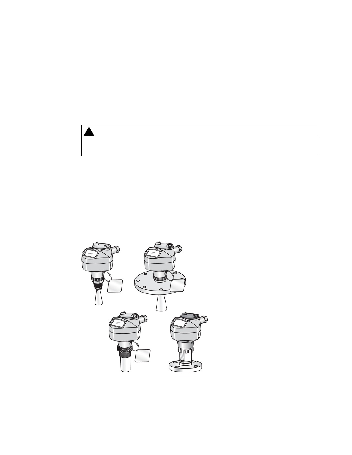
The device consists of an electronic circuit coupled to an antenna and either a threaded or
flange type process connection.
This device supports PROFIBUS PA communication protocol, and SIMATIC PDM software.
Signals are processed using Process Intelligence which has been field-proven in over 1,000,000
applications worldwide (ultrasonic and radar). This device supports acyclic communications from
both a PROFIBUS Class I and Class II master.
SITRANS LR250 (PROFIBUS PA)
Operating Instructions, 01/2014, A5E32221386-AB
13

Description
3.2
Programming
3.3
Applications
3.4
Approvals and certificates
Note
For further details see
Process Connections
3.2 Programming
This device is very easy to install and configure via a graphical local user interface (LUI). You
can modify the built in parameters either locally via the Siemens infrared handheld programmer,
or from a remote location using one of the following options:
● SIMATIC PDM
● FDT/DTM platform (such as PACTware™ or FieldCare)
● liquids and slurries
● bulk storage vessels
● simple process vessels
SITRANS LR250 is available with General Purpose approval, or for hazardous areas. In all
cases, check the nameplate on your device, and confirm the approval rating.
A wide range of process connections and antenna options are available to suit virtually any
vessel configuration.
Approvals (Page 174).
SITRANS LR250 (PROFIBUS PA)
14 Operating Instructions, 01/2014, A5E32221386-AB

4
WARNING
Note
•
•
• Installation shall only be performed by qualified personnel and in accordance with local
governing regulations.
• Handle the device using the enclosure, not the process connection tag, to avoid
damage.
• Take special care when handling the threaded PVDF and Flanged encapsulated
antennas. Any damage to the antenna surface, particularly to the tip/lens, could affect
performance.
• Materials of construction are chosen based on their chemical compatibility (or inertness)
for general purposes. For exposure to specific environments, check with chemical
compatibility charts before installing.
For European Union and member countries, installation must be according to ETSI EN
302372.
Refer to the device nameplate for approval information.
SITRANS LR250 (PROFIBUS PA)
Operating Instructions, 01/2014, A5E32221386-AB
15

Installing/mounting
4.1
Pressure applications
WARNING
Pressure applications
Note
•
•
4.1.1
Pressure Equipment Directive, PED, 97/23/EC
4.2
Mounting location
Note
•
•
4.1 Pressure applications
• Never attempt to loosen, remove, or disassemble process connection or device housing
while vessel contents are under pressure.
• The user is responsible for the selection of bolting and gasket (except for Flanged
encapsulated antenna) materials which will fall within the limits of the process
connection and its intended use and which are suitable for the service conditions.
• For Flanged encapsulated antenna, lens acts as integral gasket, no other required
• Use spring washers for Flanged encapsulated antenna.
• Improper installation may result in loss of process pressure.
The process connection tag shall remain with the process pressure boundary assembly.
(The process pressure boundary assembly comprises the components that act as a
barrier against pressure loss from the process vessel: that is, the combination of process
connection body and emitter, but normally excluding the electrical enclosure).
SITRANS LR250 units are hydrostatically tested, meeting or exceeding the requirements
of the ASME Boiler and Pressure Vessel Code and the European Pressure Equipment
Directive.
SITRANS LR250 (PROFIBUS PA)
16 Operating Instructions, 01/2014, A5E32221386-AB
Siemens Level Transmitters with flanged, threaded, or sanitary clamp type process mounts have
no pressure-bearing housing of their own and, therefore, do not come under the Pressure
Equipment Directive as pressure or safety accessories (see EU Commission Guideline 1/8 and
1/20).
Correct location is key to a successful application.
Avoid reflective interference from vessel walls and obstructions by following the
guidelines below:
Installing/mounting
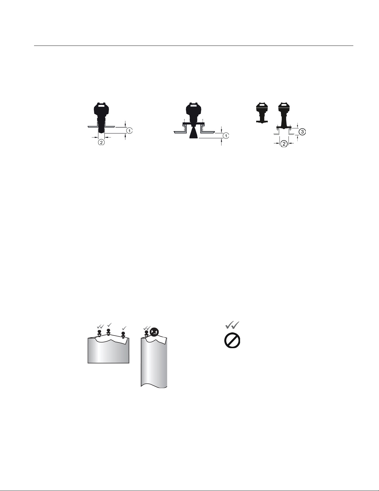
4.2.1
Nozzle design
Threaded PVDF antenna
Stainless steel horn antenna
Flanged encapsulated antenna
①
Minimum clearance: 10 mm (0.4")
②
Minimum diameter: 50 mm (2")
③
Maximum nozzle length: 500
4.2.2
Nozzle location
Preferre
Unde
4.2 Mounting location
● The end of the antenna must protrude a minimum of 10 mm (0.4") to avoid false echoes
being reflected from the nozzle
● Minimum recommended nozzle diameter for the threaded PVDF antenna is 50 mm (2").
● An antenna extension (100 mm/3.93") is available for any version except the Threaded PVDF
and Flanged encapsulated antenna (FEA).
● The maximum nozzle length for the FEA is 500 mm (20").
1)
Not applicable for FEA
● Avoid central locations on tall, narrow vessels
● Nozzle must be vertical
mm (20")
1)
.
d
SITRANS LR250 (PROFIBUS PA)
Operating Instructions, 01/2014, A5E32221386-AB
sirable
17

Installing/mounting
Environment
①
Ambient temperature
②
Process temperature (at process connection)
Antenna ① ②
392 °F)
+392 °F)
(-40 to +176 °F)
(-40 to +176 °F)
(-40 to +176 °F)
(-40 to +338 °F)
Access for programming
4.2 Mounting location
● Provide an environment suitable to the housing rating and materials of construction.
● Provide a sunshield if the device will be mounted in direct sunlight.
Horn -40 to +80 °C
(-40 to +176 °F)
PVDF -40 to +80 °C
Flanged encapsulated -40 to +80 °C
with FKM O-ring:-40 to +200 °C (-40 to
with FFKM O-ring:-20 to +200 °C (-4 to
-40 to +80 °C
-40 to +170 °C
● Provide easy access for viewing the display and programming via the handheld programmer.
SITRANS LR250 (PROFIBUS PA)
18 Operating Instructions, 01/2014, A5E32221386-AB
Installing/mounting
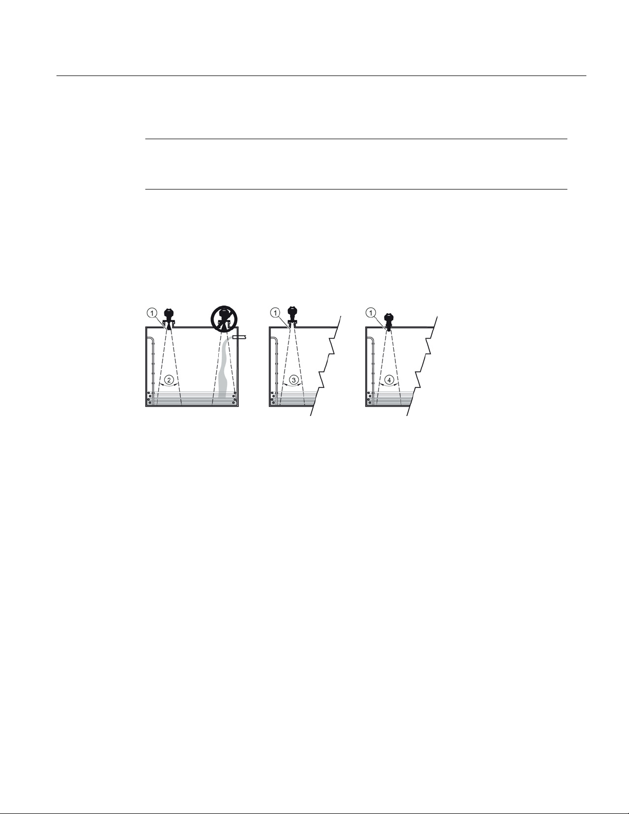
Beam angle
Note
•
•
①
Emission cone
Size
Beam angle
②
Horn
1.5"
19°
2" 15°
3"
10°
4"
8°
③
Flanged encapsulated
2"/DN50/50A
12.8°
3"/DN80/80A
9.6°
4"/DN100/100A
9.6°
6"/DN150/150A
9.6°
④
Threaded PVDF
19°
Emission cone
4.2 Mounting location
Beam width depends on antenna size: see below.
For details on avoiding false echoes, see Auto False Echo Suppression (Page 207).
● Beam angle is the width of the cone where the energy density is half of the peak energy
density.
● The peak energy density is directly in front of and in line with the antenna.
● There is a signal transmitted outside the beam angle, therefore false targets may be
detected.
● Keep emission cone free of interference from ladders, pipes, I-beams, or filling streams.
SITRANS LR250 (PROFIBUS PA)
Operating Instructions, 01/2014, A5E32221386-AB
19

Installing/mounting
4.2.3
Orientation in a vessel with obstructions
Polarization reference point
①
Polarization axis
②
Polarization reference point
③
Display
4.2.4
Mounting on a Stillpipe or Bypass Pipe
4.2 Mounting location
For best results on a vessel with obstructions, or a stillpipe with openings, orient the front or
back of the device toward the obstructions. For an illustration, see Device orientation (Page 21).
A stillpipe or bypass pipe is used for products with a low dK, or when vortex or extremely
turbulent conditions exist. It can also be used to provide optimum signal conditions on foaming
materials. See Dielectric constant of material measured in Performance (Page 170) for more
information.
SITRANS LR250 (PROFIBUS PA)
20 Operating Instructions, 01/2014, A5E32221386-AB
Installing/mounting
4.2.5
Stillpipe or Bypass Pipe requirements
Horn antenna
40 to 100 mm (1.5 to 4")
PVDF antenna
50 mm (2") only
Flanged encapsulated antenna
50 to 100 mm (2 to 4")
Not recommended:
> 100 mm (4")
Bypass vent:
Required at the upper end of the bypass 1)
1)
vessel.
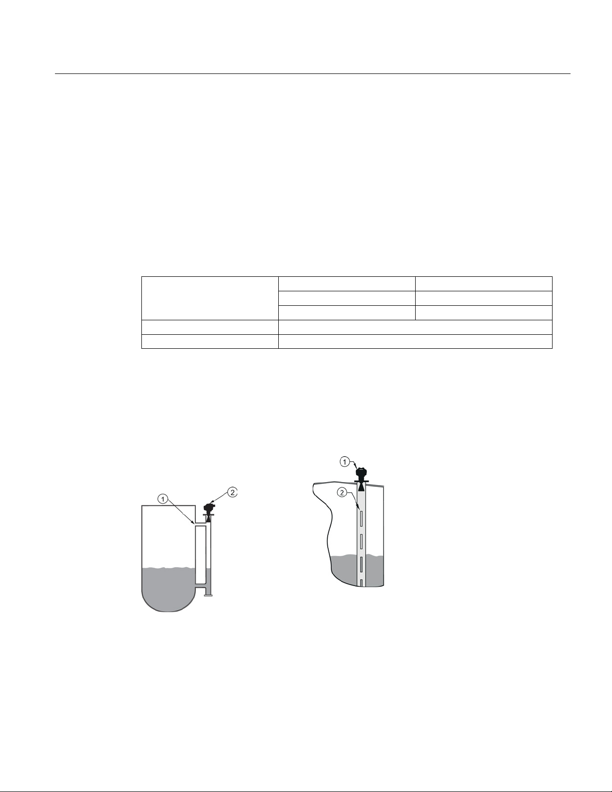
4.2.6
Device orientation
Bypass pipe installation
Stillpipe installation
①
Vent
①
Align front or back of device with stillpipe slots
②
Align front or back of device with
vents1)
②
Slots
4.2 Mounting location
● The pipe diameter must be matched with the antenna size. Use the largest antenna size that
1)
will fit the stillpipe/bypass pipe
. See Threaded Horn dimensions (Page 177) or Raised-Face
Flange per EN 1092-1 (Page 194).
● One continuous length of metallic pipe is preferred, without joints. Bad joints create
reflections.
● Joints (if unavoidable) must be machined to ± 0.25 mm (± 0.010") and must have welded
connecting sleeve on the outside.
1)
Mounting in a pipe greater than 100 mm (4") can cause large errors, and therefore is not
recommended.
Suitable pipe diameters:
To equalize pressure and keep the liquid level in the bypass constant with the liquid level in the
SITRANS LR250 (PROFIBUS PA)
Operating Instructions, 01/2014, A5E32221386-AB
1)
Horn antenna version shown as example
1)
21

Installing/mounting
4.3
Installation instructions
WARNING
Note
•
•
•
Threaded versions
Flanged versions
4.4
Flange bolting, Flanged encapsulated antenna only
Note
•
•
•
4.3 Installation instructions
For pressure applications, it will be necessary to use PTFE tape or other appropriate thread
sealing compound, and to tighten the process connection beyond hand-tight. (The
maximum recommended torque for Threaded versions is 40 N-m (30 ft.lbs.) See Flange
bolting, Flanged encapsulated antenna only (Page 22) for FEA recommended torque
values.)
On devices with a removable head, there is no limit to the number of times a device can
be rotated without damage.
When mounting, orient the front or back of the device towards the closest wall.
Do not rotate the enclosure after programming and vessel calibration, otherwise an error
may occur, caused by a polarity shift of the transmit pulse.
1. Before inserting the device into its mounting connection, check to ensure the threads are
matching, to avoid damaging them.
2. Simply screw the device into the process connection, and hand tighten, or use a wrench.
For pressure applications see Warning above.
See Flanged Horn with extension (Page 182), Raised-Face Flange per EN 1092-1 (Page 194),
Flat-Face Flange (Page 197), and Flanged encapsulated antenna (3"/DN80/80A sizes and
larger) (Page 188) for dimensions.
Use spring washers
Do not use additional gasket
Use recommended torque values for tightening bolts
SITRANS LR250 (PROFIBUS PA)
22 Operating Instructions, 01/2014, A5E32221386-AB

Installing/mounting
Flange bolting: recommended torque
Pressure class
Nominal pipe size
(NPS)
Number of bolts
Recommended torque
(Nm)
ASME B16.5, Class
150
2"
30 – 50
3"
50 – 70
4"
40 – 60
6"
70 – 90
EN1092-1, PN16 /
JIS B 2220, 10K
DN50/50A
4
DN80/80A
DN100/100A
DN150/150A
60 – 80
4.4 Flange bolting, Flanged encapsulated antenna only
4
8
8
30 – 50
SITRANS LR250 (PROFIBUS PA)
Operating Instructions, 01/2014, A5E32221386-AB
23

Installing/mounting
Recommendations for flange bolting:
4.4 Flange bolting, Flanged encapsulated antenna only
● Use cross-pattern sequence as shown
● Check uniformity of the flange gap
● Apply adjustments by selective tightening if required
● Torque incrementally until desired value is reached
● Check/re-torque after 4 to 6 hours
● Check bolts periodically, re-torque as required
● Use new lens, O-ring and spring washers after removal from installation.
For instructions on replacing the lens, see Part replacement (Page 159).
SITRANS LR250 (PROFIBUS PA)
24 Operating Instructions, 01/2014, A5E32221386-AB

5
5.1
Power
WARNING
Note
All field wiring must have insulation suitable for rated voltages.
The DC input terminals shall be supplied from a source providing electrical isolation
between the input and output, in order to meet the applicable safety requirements of IEC
61010-1.
SITRANS LR250 (PROFIBUS PA)
Operating Instructions, 01/2014, A5E32221386-AB
25
Connecting
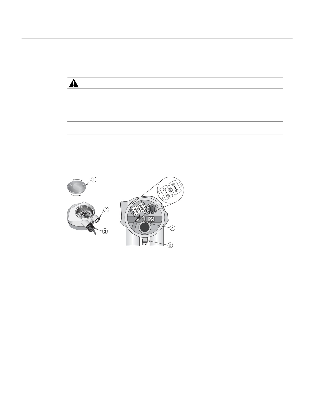
5.2
Connecting SITRANS LR250
WARNING
Note
•
①
Use a 2 mm Allen key to loosen the lid
④
Cable shield
②
Plug (IP 68)
⑤
Ground terminal
③
Optional cable gland
a)
b)
applications.
5.2 Connecting SITRANS LR250
• Check the nameplate on your device, to verify the approval rating.
• Use appropriate conduit seals to maintain IP or NEMA rating.
• See Wiring setups for hazardous area installations (Page 28).
Separate cables and conduits may be required to conform to standard instrumentation
wiring practices or electrical codes.
a) b)
(or NPT cable entry)b)
-lock set screw
May be shipped with the device.
If cable is routed through conduit, use only approved suitable-size hubs for waterproof
SITRANS LR250 (PROFIBUS PA)
26 Operating Instructions, 01/2014, A5E32221386-AB

Connecting
Wiring instructions
Note
•
•
•
PROFIBUS PA (
5.2 Connecting SITRANS LR250
1. Strip the cable jacket for approximately 70 mm (2.75") from the end of the cable, and thread
the wires through the gland. (If cable is routed through conduit, use only approved suitablesize hubs for waterproof applications.)
2. Connect the wires to the terminals as shown: the polarity is identified on the terminal block.
3. Ground the device according to local regulations.
4. Tighten the gland to form a good seal.
5. Close the lid and secure the locking screw before programming and device configuration.
PROFIBUS PA cable shield must be terminated at both ends of the cable for it to work
properly.
If a Weidmüller or other current limiting junction box is connected to this device, please
ensure that the current limit is set to 40 mA or higher.
Please refer to the PROFIBUS PA User and Installation Guidelines (order number 2.092)
for information on installing PROFIBUS devices at:
http://www.profibus.com/)
SITRANS LR250 (PROFIBUS PA)
Operating Instructions, 01/2014, A5E32221386-AB
27
 Loading...