

Siemens SITRANS LR250 Operating Instructions Manual

SITRANS LR250 (FOUNDATION
FIELDBUS)
___________________
___________________
___________________
___________________
___________________
___________________
___________________
___________________
___________________
___________________
___________________
___________________
___________________
___________
___________________
___________________
___________________
SITRANS
Radar Transmitters
SITRANS LR250 (FOUNDATION
FIELDBUS)
Operating Instructions
08/2014
Introduction
1
Safety information
2
Description
3
Installing/mounting
4
Connecting
5
Commissioning
6
Remote operation
7
Parameter reference
8
Service and maintenance
9
Diagnosing and
troubleshooting
10
Technical data
11
Dimension drawings
12
Appendix A: Technical
reference
A
Appendix B:
Communications via
Foundation Fieldbus
B
Appendix C: Certificates and
support
C
List of abbreviations
13
LCD menu structure
14
A5E32221411-AC
Legal information
Warning notice system
DANGER
will
WARNING
may
CAUTION
NOTICE
Qualified Personnel
personnel qualified
Proper use of Siemens products
WARNING
Trademarks
Disclaimer of Liability
This manual contains notices you have to observe in order to ensure your personal safety, as well as to prevent
damage to property. The notices referring to your personal safety are highlighted in the manual by a safety alert
symbol, notices referring only to property damage have no safety alert symbol. These notices shown below are
graded according to the degree of danger.
indicates that death or severe personal injury
indicates that death or severe personal injury
indicates that minor personal injury can result if proper precautions are not taken.
indicates that property damage can result if proper precautions are not taken.
If more than one degree of danger is present, the warning notice representing the highest degree of danger will be
used. A notice warning of injury to persons with a safety alert symbol may also include a warning relating to property
damage.
The product/system described in this documentation may be operated only by
in accordance with the relevant documentation, in particular its warning notices and safety instructions. Qualified
personnel are those who, based on their training and experience, are capable of identifying risks and avoiding
potential hazards when working with these products/systems.
result if proper precautions are not taken.
result if proper precautions are not taken.
for the specific task
Note the following:
Siemens products may only be used for the applications described in the catalog and in the relevant technical
documentation. If products and components from other manufacturers are used, these must be recommended
or approved by Siemens. Proper transport, storage, installation, assembly, commissioning, operation and
maintenance are required to ensure that the products operate safely and without any problems. The permissible
ambient conditions must be complied with. The information in the relevant documentation must be observed.
All names identified by ® are registered trademarks of Siemens AG. The remaining trademarks in this publication may
be trademarks whose use by third parties for their own purposes could violate the rights of the owner.
We have reviewed the contents of this publication to ensure consistency with the hardware and software described.
Since variance cannot be precluded entirely, we cannot guarantee full consistency. However, the information in this
publication is reviewed regularly and any necessary corrections are included in subsequent editions.
Siemens AG
Industry Sector
Postfach 48 48
90026 NÜRNBERG
GERMANY
Order number: A5E32221411
Ⓟ 05/2014 Subject to change
Copyright © Siemens AG 2014.
All rights reserved

Table of contents
1 Introduction ........................................................................................................................................... 11
2 Safety information ................................................................................................................................. 15
3 Description ............................................................................................................................................ 19
4 Installing/mounting ................................................................................................................................ 21
1.1 LR250 FF manual usage ............................................................................................................. 11
1.2 Purpose of this documentation .................................................................................................... 11
1.3 Document history ......................................................................................................................... 11
1.4 Firmware revision history ............................................................................................................. 12
1.5 Designated use ............................................................................................................................ 12
1.6 Checking the consignment ........................................................................................................... 13
1.7 Transportation and storage .......................................................................................................... 13
1.8 Notes on warranty ........................................................................................................................ 13
2.1 Preconditions for safe use ........................................................................................................... 15
2.1.1 Safety marking symbols ............................................................................................................... 15
2.1.2 Laws and directives ..................................................................................................................... 15
2.1.3 FCC Conformity ........................................................................................................................... 15
2.1.4 Conformity with European directives ........................................................................................... 16
2.1.5 CE Electromagnetic Compatibility (EMC) Conformity.................................................................. 17
2.2 Improper device modifications ..................................................................................................... 17
2.3 Requirements for special applications ......................................................................................... 18
2.4 Use in hazardous areas ............................................................................................................... 18
3.1 SITRANS LR250 overview ........................................................................................................... 19
3.2 Programming ................................................................................................................................ 20
3.3 Applications .................................................................................................................................. 20
3.4 Approvals and certificates ............................................................................................................ 20
4.1 Basic safety information ............................................................................................................... 21
4.1.1 Pressure applications ................................................................................................................... 22
4.1.1.1 Pressure Equipment Directive, PED, 97/23/EC ........................................................................... 23
4.2 Installation location requirements ................................................................................................ 24
4.3 Proper mounting........................................................................................................................... 26
4.3.1 Nozzle design ............................................................................................................................... 27
SITRANS LR250 (FOUNDATION FIELDBUS)
Operating Instructions, 08/2014, A5E32221411-AC
3

Table of contents
5 Connecting ............................................................................................................................................41
6 Commissioning ......................................................................................................................................55
7 Remote operation ..................................................................................................................................79
4.3.2 Nozzle location ............................................................................................................................ 28
4.3.3 Orientation in a vessel with obstructions ..................................................................................... 31
4.3.4 Mounting on a Stillpipe or Bypass Pipe ...................................................................................... 32
4.3.5 Device orientation ....................................................................................................................... 33
4.4 Installation instructions ................................................................................................................ 34
4.4.1 Threaded versions ...................................................................................................................... 36
4.4.2 Flanged versions ......................................................................................................................... 37
4.4.3 Hygienic versions ........................................................................................................................ 39
4.5 Disassembly ................................................................................................................................ 40
5.1 Basic safety information .............................................................................................................. 41
5.2 Connecting SITRANS LR250 ...................................................................................................... 42
5.3 Wiring setups for hazardous area installation ............................................................................. 46
5.3.1 Configuration with Foundation Fieldbus for hazardous areas .................................................... 46
5.3.2 Intrinsically safe wiring ................................................................................................................ 48
5.3.2.1 Intrinsically safe wiring (FM/CSA) ............................................................................................... 48
5.3.3 Non-sparking wiring .................................................................................................................... 51
5.3.4 Non-incendive wiring (US/Canada only) ..................................................................................... 51
5.4 Instructions specific to hazardous area installations ................................................................... 52
5.4.1 (Reference European ATEX Directive 94/9/EC, Annex II, 1/0/6) ............................................... 52
6.1 Basic safety information .............................................................................................................. 55
6.2 Operating via the handheld programmer .................................................................................... 55
6.2.1 Power up ..................................................................................................................................... 56
6.2.2 Handheld programmer functions ................................................................................................. 56
6.2.2.1 The LCD display .......................................................................................................................... 57
6.2.2.2 Handheld programmer (Part No. 7ML1930-1BK) ....................................................................... 59
6.2.3 Programming ............................................................................................................................... 60
6.2.3.1 Quick Start Wizard via the handheld programmer_note ............................................................. 65
6.2.3.2 Auto False Echo Suppression ..................................................................................................... 69
6.2.3.3 Requesting an Echo Profile ........................................................................................................ 70
6.2.3.4 Device Address ........................................................................................................................... 71
6.3 Application examples .................................................................................................................. 71
6.3.1 Liquid resin in storage vessel, level measurement ..................................................................... 72
6.3.2 Horizontal vessel with volume measurement.............................................................................. 74
6.3.3 Application with stillpipe .............................................................................................................. 76
7.1 Operating via AMS Device Manager ........................................................................................... 79
7.1.1 Functions in AMS Device Manager ............................................................................................. 79
7.1.2 Key features of AMS Device Manager Rev. 9.0 ......................................................................... 81
7.1.2.1 Pull-down menu access .............................................................................................................. 82
SITRANS LR250 (FOUNDATION FIELDBUS)
4 Operating Instructions, 08/2014, A5E32221411-AC

Table of contents
8 Parameter reference ........................................................................................................................... 143
7.1.3 Adding a new device .................................................................................................................... 82
7.1.3.1 Electronic Device Description (EDD) ........................................................................................... 82
7.1.4 Master Reset ................................................................................................................................ 84
7.1.5 Scan Device ................................................................................................................................. 84
7.1.6 Sensor calibration ........................................................................................................................ 85
7.1.7 Configuring a new device ............................................................................................................. 85
7.1.7.1 Quick Start Wizard via AMS Device Manager ............................................................................. 85
7.1.8 Changing parameter settings using AMS Device Manager ......................................................... 91
7.1.9 Configure/Setup (Level Transducer Block-LTB) .......................................................................... 92
7.1.9.1 Identification (LTB) ....................................................................................................................... 92
7.1.9.2 Operation (LTB) ........................................................................................................................... 93
7.1.9.3 Setup (LTB) .................................................................................................................................. 95
7.1.9.4 Linearization (LTB) ....................................................................................................................... 97
7.1.9.5 Signal processing ......................................................................................................................... 99
7.1.9.6 Maintenance & Diagnostics (LTB) ............................................................................................. 104
7.1.9.7 Communication (LTB) ................................................................................................................ 107
7.1.10 Configure/Setup (Liquid Crystal Display Block-LCD)................................................................. 107
7.1.10.1 Identification (LCD) .................................................................................................................... 107
7.1.10.2 Operation (LCD) ......................................................................................................................... 108
7.1.10.3 Setup (LCD) ............................................................................................................................... 109
7.1.10.4 Communication (LCD) ............................................................................................................... 109
7.1.11 Configure/Setup (Diagnostic Transducer Block-DIAG) ............................................................. 110
7.1.11.1 Identification (DIAG) ...................................................................................................................
7.1.
11.2 Operation (DIAG) ....................................................................................................................... 110
110
7.1.11.3 Communication (DIAG) .............................................................................................................. 111
7.1.12 Configure/Setup (Resource Block - RESOURCE) ..................................................................... 111
7.1.12.1 Identification (RESOURCE) ....................................................................................................... 111
7.1.12.2 Wizards (RESOURCE) .............................................................................................................. 112
7.1.12.3 Operation (RESOURCE) ........................................................................................................... 113
7.1.12.4 Maintenance & Diagnostics (RESOURCE) ............................................................................... 116
7.1.12.5 Communication (RESOURCE) .................................................................................................. 118
7.1.12.6 Security (RESOURCE) .............................................................................................................. 119
7.1.13 Device Diagnostics (Level Transducer Block - LTB) ................................................................. 119
7.1.13.1 Alarms & Errors (LTB) ................................................................................................................ 120
7.1.13.2 Extended Diagnostics (LTB) ...................................................................................................... 123
7.1.14 Device Diagnostics (Liquid Crystal Display Block - LCD) .......................................................... 124
7.1.14.1 Alarms & Errors (LCD) ............................................................................................................... 124
7.1.15 Device Diagnostics (Diagnostic Transducer Block - DIAG) ....................................................... 124
7.1.15.1 Alarms & Errors (DIAG) ............................................................................................................. 124
7.1.16 Device Diagnostics (Resource Block - RESOURCE) ................................................................ 124
7.1.16.1 Alarms & Errors (RESOURCE) .................................................................................................. 124
7.1.16.2 Extended Diagnostics (RESOURCE) ........................................................................................ 127
7.1.17 Process Variables (Level Transducer Block - LTB) ................................................................... 128
7.1.18 Password Protection .................................................................................................................. 129
7.1.18.1 User Manager utility ................................................................................................................... 129
7.1.19 AMS menu structure ..................................................................................................................
130
SITRANS LR250 (FOUNDATION FIELDBUS)
Operating Instructions, 08/2014, A5E32221411-AC
5

Table of contents
9 Service and maintenance ..................................................................................................................... 197
10 Diagnosing and troubleshooting ........................................................................................................... 203
11 Technical data ..................................................................................................................................... 213
12 Dimension drawings ............................................................................................................................. 221
8.1 Alphabetical parameter list ........................................................................................................ 191
9.1 Basic safety information ............................................................................................................ 197
9.2 Cleaning .................................................................................................................................... 197
9.3 Maintenance and repair work .................................................................................................... 198
9.3.1 Unit repair and excluded liability ............................................................................................... 199
9.3.2 Part replacement ....................................................................................................................... 199
9.4 Disposal .................................................................................................................................... 201
10.1 Device status icons ................................................................................................................... 204
10.2 General fault codes ................................................................................................................... 205
10.3 Operation troubleshooting ......................................................................................................... 210
11.1 Power ........................................................................................................................................ 213
11.2 Performance .............................................................................................................................. 213
11.3 Interface .................................................................................................................................... 215
11.4 Mechanical ................................................................................................................................ 215
11.5 Environmental ........................................................................................................................... 218
11.6 Process ..................................................................................................................................... 218
11.7 Approvals .................................................................................................................................. 219
11.8 Programmer (infrared keypad) .................................................................................................. 220
12.1 Threaded horn antenna............................................................................................................. 221
12.2 Threaded horn antenna with extension ..................................................................................... 224
12.3 Flanged horn antenna ............................................................................................................... 226
12.4 Flanged horn antenna with extension ....................................................................................... 228
12.5 Flanged encapsulated antenna (2"/DN50/50A sizes only) ....................................................... 230
12.6 Flanged encapsulated antenna (3"/DN80/80A sizes and larger) .............................................. 232
12.7 Hygienic encapsulated antenna (2" ISO 2852 sanitary clamp) ................................................ 234
12.8 Hygienic encapsulated antenna (3" ISO 2852 sanitary clamp) ................................................ 235
12.9 Hygienic encapsulated antenna (4" ISO 2852 sanitary clamp) ................................................ 236
12.10 Hygienic encapsulated antenna (DN 50 nozzle/ slotted nut to DIN 11851) .............................. 237
12.11 Hygienic encapsulated antenna (DN 80 nozzle/ slotted nut to DIN 11851) .............................. 238
SITRANS LR250 (FOUNDATION FIELDBUS)
6 Operating Instructions, 08/2014, A5E32221411-AC

Table of contents
A Appendix A: Technical reference ......................................................................................................... 265
12.12 Hygienic encapsulated antenna (DN 100 nozzle/ slotted nut to DIN 11851) ............................ 239
12.13 Hygienic encapsulated antenna (DN 50 aseptic slotted nut to DIN 11864-1) ........................... 240
12.14 Hygienic encapsulated antenna (DN 80 aseptic slotted nut to DIN 11864-1) ........................... 241
12.15 Hygienic encapsulated antenna (DN 100 aseptic slotted nut to DIN 11864-1) ......................... 242
12.16 Hygienic encapsulated antenna (DN 50 aseptic flange to DIN 11864-2) .................................. 243
12.17 Hygienic encapsulated antenna (DN 80 aseptic flange to DIN 11864-2) .................................. 244
12.18 Hygienic encapsulated antenna (DN 100 aseptic flange to DIN 11864-2) ................................ 245
12.19 Hygienic encapsulated antenna (DN 50 aseptic clamp to DIN 11864-3) .................................. 246
12.20 Hygienic encapsulated antenna (DN 80 aseptic clamp to DIN 11864-3) .................................. 247
12.21 Hygienic encapsulated antenna (DN 100 aseptic clamp to DIN 11864-3) ................................ 248
12.22 Hygienic encapsulated antenna (Tuchenhagen Type N) .......................................................... 249
12.23 Hygienic encapsulated antenna (Tuchenhagen Type F) ........................................................... 250
12.24 Threaded PVDF antenna ........................................................................................................... 251
12.25 Threaded connection markings .................................................................................................. 252
12.26 Raised-Face flange per EN 1092-1 for flanged horn antenna ................................................... 253
12.27 Raised-Face flange per EN 1092-1 for flanged encapsulated antenna..................................... 255
12.28 Flat-Face flange ......................................................................................................................... 258
12.29 Aseptic/hygienic flange DN50, DN80, DN100 for DIN 11864-2 ................................................. 261
12.30 Process connection tag (pressure rated versions) .................................................................... 264
A.1 Principles of operation ............................................................................................................... 265
A.2 Echo processing......................................................................................................................... 266
A.2.1 Process Intelligence ................................................................................................................... 266
A.2.2 Echo Selection ........................................................................................................................... 266
A.2.3 CLEF Range .............................................................................................................................. 269
A.2.4 Measurement Response ............................................................................................................ 270
A.2.5 Echo Threshold .......................................................................................................................... 270
A.2.6 Echo Lock .................................................................................................................................. 271
A.2.7 Auto False Echo Suppression .................................................................................................... 271
A.2.8 Measurement Range ................................................................................................................. 273
A.2.9 Damping ..................................................................................................................................... 273
A.2.10 Loss of Echo (LOE) .................................................................................................................... 274
A.2.10.1 LOE Timer .................................................................................................................................. 274
A.3 Maximum Process Temperature Chart ...................................................................................... 274
A.4 Process Pressure/Temperature derating curves ....................................................................... 276
A.4.1 Pressure Equipment Directive, PED, 97/23/EC ......................................................................... 277
SITRANS LR250 (FOUNDATION FIELDBUS)
Operating Instructions, 08/2014, A5E32221411-AC
7

Table of contents
B Appendix B: Communications via Foundation Fieldbus ........................................................................ 291
C Appendix C: Certificates and support ................................................................................................... 293
13 List of abbreviations ............................................................................................................................. 295
14 LCD menu structure ............................................................................................................................. 296
Glossary .............................................................................................................................................. 301
Index ................................................................................................................................................... 307
A.4.2 Horn antenna ............................................................................................................................ 278
A.4.3 Flanged horn antenna ............................................................................................................... 279
A.4.4 Flanged encapsulated antenna ................................................................................................. 284
A.4.5 PVDF antenna ........................................................................................................................... 286
A.4.6 Hygienic encapsulated antenna ................................................................................................ 287
B.1 Field Communicator 375 (F375) ............................................................................................... 291
C.1 Certificates ................................................................................................................................ 293
C.2 Technical support ...................................................................................................................... 293
SITRANS LR250 (FOUNDATION FIELDBUS)
8 Operating Instructions, 08/2014, A5E32221411-AC

Table of contents
SITRANS LR250 (FOUNDATION FIELDBUS)
Operating Instructions, 08/2014, A5E32221411-AC
9


1
1.1
LR250 FF manual usage
Note
1.2
Purpose of this documentation
1.3
Document history
Edition
Remark
This manual applies to the SITRANS LR250 (FOUNDATION™ Fieldbus) only.
FOUNDATION™ Fieldbus is a trademark of Fieldbus Foundation.
Follow these operating instructions for quick, trouble-free installation, and maximum accuracy
and reliability of your device.
We always welcome suggestions and comments about manual content, design, and
accessibility. Please direct your comments to:
Technical publications (mailto:techpubs.smpi@siemens.com
These instructions contain all information required to commission and use the device. It is your
responsibility to read the instructions carefully prior to installation and commissioning. In order to
use the device correctly, first review its principle of operation.
The instructions are aimed at persons mechanically installing the device, connecting it
electronically, configuring the parameters and commissioning it, as well as service and
maintenance engineers.
The following table notes major changes in the documentation compared to the previous edition.
January 2014
August 2014
• Flanged encapsulated antenna version added.
• Hygienic encapsulated antenna version added.
)
SITRANS LR250 (FOUNDATION FIELDBUS)
Operating Instructions, 08/2014, A5E32221411-AC
11

Introduction
1.4
Firmware revision history
Firmware
rev.
PDM EDD
rev.
Date
Changes
1.5
Designated use
Note
Use in a domestic environment
1.4 Firmware revision history
This history establishes the correlation between the current documentation and the valid
firmware of the device.
The documentation of this edition is applicable for the following firmware:
1.01.00 1.01.00 25 Feb 2010
1.01.04 1.01.00 2 Aug 2011
1.01.05 1.01.00 31 Oct 2012
Use the device to measure process media in accordance with the information in the operating
instructions.
This is a Class A Group 1 equipment intended for use in industrial areas.
In a domestic environment this device may cause radio interference.
• Initial release.
• Threaded PVDF antenna supported.
• Antenna parameter removed.
• Quickstart on local display enhancements.
SITRANS LR250 (FOUNDATION FIELDBUS)
12 Operating Instructions, 08/2014, A5E32221411-AC

Introduction
1.6
Checking the consignment
WARNING
Using a damaged or incomplete device
1.7
Transportation and storage
CAUTION
Insufficient protection during storage
1.8
Notes on warranty
1.6 Checking the consignment
1. Check the packaging and the device for visible damage caused by inappropriate handling
during shipping.
2. Report any claims for damages immediately to the shipping company.
3. Retain damaged parts for clarification.
4. Check the scope of delivery by comparing your order to the shipping documents for
correctness and completeness.
Danger of explosion in hazardous areas.
• Do not use damaged or incomplete devices.
To guarantee sufficient protection during transport and storage, observe the following:
● Keep the original packaging for subsequent transportation.
● Devices/replacement parts should be returned in their original packaging.
● If the original packaging is no longer available, ensure that all shipments are properly
packaged to provide sufficient protection during transport. Siemens cannot assume liability
for any costs associated with transportation damages.
The packaging only provides limited protection against moisture and infiltration.
• Provide additional packaging as necessary.
The contents of this manual shall not become part of or modify any prior or existing agreement,
commitment or legal relationship. The sales contract contains all obligations on the part of
Siemens as well as the complete and solely applicable warranty conditions. Any statements
regarding device versions described in the manual do not create new warranties or modify the
existing warranty.
The content reflects the technical status at the time of publishing. Siemens reserves the right to
make technical changes in the course of further development.
SITRANS LR250 (FOUNDATION FIELDBUS)
Operating Instructions, 08/2014, A5E32221411-AC
13

2
2.1
Preconditions for safe use
2.1.1
Safety marking symbols
In manual
On product
Description
2.1.2
Laws and directives
2.1.3
FCC Conformity
US Installations only: Federal Communications Commission (FCC) rules
WARNING
This device left the factory in good working condition. In order to maintain this status and to
ensure safe operation of the device, observe these instructions and all the specifications
relevant to safety.
Observe the information and symbols on the device. Do not remove any information or symbols
from the device. Always keep the information and symbols in a completely legible state.
Observe the test certification, provisions and laws applicable in your country during connection,
assembly and operation.
Changes or modifications not expressly approved by Siemens Milltronics could void the
user’s authority to operate the equipment.
(Label on product:
yellow
background.)
WARNING: refer to accompanying documents (manual) for
details.
SITRANS LR250 (FOUNDATION FIELDBUS)
Operating Instructions, 08/2014, A5E32221411-AC
15

Safety information
Note
2.1.4
Conformity with European directives
potentially explosive atmospheres.
2.1 Preconditions for safe use
• This equipment has been tested and found to comply with the limits for a Class A digital
device, pursuant to Part 15 of the FCC Rules. These limits are designed to provide
reasonable protection against harmful interference when the equipment is operated in a
commercial environment.
• This equipment generates, uses, and can radiate radio frequency energy and, if not
installed and used in accordance with the instruction manual, may cause harmful
interference to radio communications. Operation of this equipment in a residential area is
likely to cause harmful interference to radio communications, in which case the user will
be required to correct the interference at his own expense.
The CE marking on the device symbolizes the conformity with the following European directives:
Electromagnetic
compatibility EMC
2004/108/EC
Low voltage directive LVD
2006/95/EC
Atmosphère explosible
ATEX
94/9/EC
Directive of the European Parliament and of the Council on the
approximation of the laws of the Member States relating to
electromagnetic compatibility and repealing Directive
89/336/EEC.
Directive of the European Parliament and of the Council on the
harmonisation of the laws of Member States relating to
electrical equipment designed for use within certain voltage
limits.
Directive of the European Parliament and the Council on the
approximation of the laws of the Member States concerning
equipment and protective systems intended for use in
Radio and
telecommunications terminal
equipment R&TTE
1999/5/EC
The applicable directives can be found in the EC conformity declaration of the specific device.
SITRANS LR250 (FOUNDATION FIELDBUS)
16 Operating Instructions, 08/2014, A5E32221411-AC
Directive of the European Parliament and of the Council on
radio equipment and telecommunications terminal equipment
and the mutual recognition of their conformity.

Safety information
2.1.5
CE Electromagnetic Compatibility (EMC) Conformity
EMC Standard
Title
2.2
Improper device modifications
WARNING
Improper device modifications
2.2 Improper device modifications
This equipment has been tested and found to comply with the following EMC Standards:
CISPR 11:2009 + A1:2010/EN
55011:2009 + A1:2010, CLASS A
EN 61326:2013
(IEC 61326:2012)
EN61000-4-2:2009 Electromagnetic Compatibility (EMC) Part 4-2:
EN61000-4-3:2006 + A1:2008 + A2:2010 Electromagnetic Compatibility (EMC) Part 4-3:
EN61000-4-4:2004 + A1:2010 Electromagnetic Compatibility (EMC) Part 4-4:
EN61000-4-5:2006 Electromagnetic Compatibility (EMC) Part 4-5:
EN61000-4-6:2010 Electromagnetic Compatibility (EMC) Part 4-6:
EN61000-4-8:2010 Electromagnetic Compatibility (EMC) Part 4-8:
Limits and methods of measurements of radio
disturbance characteristics of industrial, scientific,
and medical (ISM) radio-frequency equipment
Electrical Equipment for Measurement, Control and
Laboratory Use – Electromagnetic Compatibility.
Testing and measurement techniques –
Electrostatic discharge immunity test.
Testing and measurement techniques – Radiated,
radio-frequency, electromagnetic field immunity test
2006 + A1:2008 + A2:2010.
Testing and measurement techniques – Electrical
fast transient/burst immunity test.
Testing and measurement techniques – Surge
immunity test.
Testing and measurement techniques – Immunity to
conducted disturbances, induced by radiofrequency fields.
Testing and measurement techniques – Power
frequency magnetic field immunity test.
SITRANS LR250 (FOUNDATION FIELDBUS)
Operating Instructions, 08/2014, A5E32221411-AC
Danger to personnel, system and environment can result from modifications to the device,
particularly in hazardous areas.
• Only carry out modifications that are described in the instructions for the device. Failure
to observe this requirement cancels the manufacturer's warranty and the product
approvals.
17

Safety information
2.3
Requirements for special applications
Note
Operation under special ambient conditions
2.4
Use in hazardous areas
Qualified personnel for hazardous area applications
WARNING
Loss of safety of device with type of protection "Intrinsic safety Ex i"
2.3 Requirements for special applications
Due to the large number of possible applications, each detail of the described device versions
for each possible scenario during commissioning, operation, maintenance or operation in
systems cannot be considered in the instructions. If you need additional information not covered
by these instructions, contact your local Siemens office or company representative.
We highly recommend that you contact your Siemens representative or our application
department before you operate the device under special ambient conditions as can be
encountered in nuclear power plants or when the device is used for research and
development purposes.
Persons who install, connect, commission, operate, and service the device in a hazardous area
must have the following specific qualifications:
● They are authorized, trained or instructed in operating and maintaining devices and systems
according to the safety regulations for electrical circuits, high pressures, aggressive, and
hazardous media.
● They are authorized, trained, or instructed in carrying out work on electrical circuits for
hazardous systems.
● They are trained or instructed in maintenance and use of appropriate safety equipment
according to the pertinent safety regulations.
If the device has already been operated in non-intrinsically safe circuits or the electrical
specifications have not been observed, the safety of the device is no longer ensured for use
in hazardous areas. There is a danger of explosion.
• Connect the device with type of protection "Intrinsic safety" solely to an intrinsically safe
circuit.
• Observe the specifications for the electrical data on the certificate.
SITRANS LR250 (FOUNDATION FIELDBUS)
18 Operating Instructions, 08/2014, A5E32221411-AC
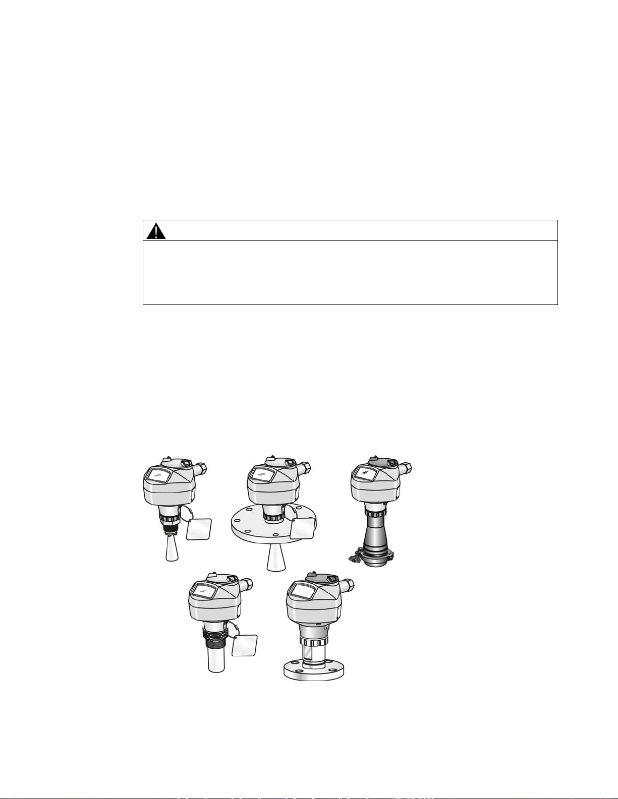
3
3.1
SITRANS LR250 overview
WARNING
Loss of protection
Danger to personnel, system and environment can result from improper use of the device.
• SITRANS LR250 is to be used only in the manner outlined in this manual, otherwise
protection provided by the device may be impaired.
SITRANS LR250 is a 2-wire 25 GHz pulse radar level transmitter for continuous monitoring of
liquids and slurries in storage vessels including high pressure and high temperature, to a range
of 20 meters (66 feet). It is ideal for small vessels, material such as chemicals, food, beverages,
solvents (including those of corrosive or aggressive nature), and low dielectric media.
The device consists of an electronic circuit coupled to an antenna and either a threaded or
flange type process connection.
This device supports Foundation Fieldbus (FF) communication protocol. Signals are processed
using Process Intelligence which has been field proven in over 1,000,000 applications worldwide
(ultrasonic and radar). This device can be configured as an FF (H1) Link Master.
SITRANS LR250 (FOUNDATION FIELDBUS)
Operating Instructions, 08/2014, A5E32221411-AC
19

Description
3.2
Programming
3.3
Applications
3.4
Approvals and certificates
Note
Process Connections
3.2 Programming
This device is very easy to install and configure via a graphical local user interface (LUI). You
can modify the built in parameters either locally via the Siemens infrared handheld programmer,
or from a remote location using one of the following options:
● FF host system
● AMS Device Manager
● liquids and slurries
● bulk storage vessels
● simple process vessels
● corrosive and aggressive
● hygienic/sanitary
For further details see Approvals (Page 219).
SITRANS LR250 is available with approvals for General purpose, sanitary or hygienic and for
hazardous areas. In all cases, check the nameplate on your device, and confirm the approval
rating.
A wide range of process connections and antenna options are available to suit virtually any
vessel configuration.
SITRANS LR250 (FOUNDATION FIELDBUS)
20 Operating Instructions, 08/2014, A5E32221411-AC

4
4.1
Basic safety information
Note
Material compatibility
WARNING
Unsuitable connecting parts
WARNING
Exceeded maximum ambient or process media temperature
WARNING
Open cable inlet or incorrect cable gland
Siemens can provide you with support concerning selection of sensor components wetted by
process media. However, you are responsible for the selection of components. Siemens
accepts no liability for faults or failures resulting from incompatible materials.
Danger of injury or poisoning.
In case of improper mounting hot, toxic and corrosive process media could be released at
the connections.
• Ensure that connecting parts (such as flange gaskets and bolts) are suitable for
connection and process media.
Danger of explosion in hazardous areas.
Device damage.
• Make sure that the maximum permissible ambient and process media temperatures of
the device are not exceeded.
Danger of explosion in hazardous areas.
• Close the cable inlets for the electrical connections. Only use cable glands or plugs
which are approved for the relevant type of protection.
SITRANS LR250 (FOUNDATION FIELDBUS)
Operating Instructions, 08/2014, A5E32221411-AC
21
Installing/mounting
WARNING
Incorrect conduit system
4.1.1
Pressure applications
DANGER
Pressure applications
WARNING
Pressure applications
WARNING
Exceeded maximum permissible operating pressure
4.1 Basic safety information
Danger of explosion in hazardous areas as result of open cable inlet or incorrect conduit
system.
• In the case of a conduit system, mount a spark barrier at a defined distance from the
device input. Observe national regulations and the requirements stated in the relevant
approvals.
Danger to personnel, system and environment will result from improper disassembly.
• Never attempt to loosen, remove, or disassemble process connection while vessel
contents are under pressure.
Danger to personnel, system and environment can result from improper installation.
• Improper installation may result in loss of process pressure.
Danger of injury or poisoning.
The maximum permissible operating pressure depends on the device version. The device
can be damaged if the operating pressure is exceeded. Hot, toxic and corrosive process
media could be released.
• Make sure that the device is suitable for the maximum permissible operating pressure of
your system.
SITRANS LR250 (FOUNDATION FIELDBUS)
22 Operating Instructions, 08/2014, A5E32221411-AC

Installing/mounting
Note
Note
4.1.1.1
Pressure Equipment Directive, PED, 97/23/EC
4.1 Basic safety information
• The process connection tag shall remain with the process pressure boundary assembly.
(The process pressure boundary assembly comprises the components that act as a
barrier against pressure loss from the process vessel: that is, the combination of process
connection body and emitter, but normally excluding the electrical enclosure). In the
event the device package is replaced, the process connection tag shall be transferred to
the replacement unit.
• SITRANS LR250 units are hydrostatically tested, meeting or exceeding the requirement
of the ASME Boiler and Pressure Vessel Code and the European Pressure Equipment
Directive.
• The serial numbers stamped in each process connection body, (flange, threaded, or
sanitary), provide a unique identification number indicating date of manufacture.
Example: MMDDYY – XXX (where MM = month, DD = day, YY = year, and XXX=
sequential unit produced)
• Further markings (space permitting) indicate flange configuration, size, pressure class,
material, and material heat code.
Siemens Level Transmitters with flanged, threaded, or sanitary clamp type process mounts have
no pressure-bearing housing of their own and, therefore, do not come under the Pressure
Equipment Directive as pressure or safety accessories (see EU Commission Guideline 1/8 and
1/20).
SITRANS LR250 (FOUNDATION FIELDBUS)
Operating Instructions, 08/2014, A5E32221411-AC
23

Installing/mounting
4.2
Installation location requirements
WARNING
Aggressive atmospheres
CAUTION
Direct sunlight
4.2 Installation location requirements
Danger to personnel, system and environment can result from unsuitable environment.
• Provide an environment suitable to the housing rating and materials of construction.
Device damage.
The device can overheat or materials become brittle due to UV exposure.
• Protect the device from direct sunlight.
• Make sure that the maximum permissible ambient temperature is not exceeded. Refer
to the information in Chapter "Technical data".
SITRANS LR250 (FOUNDATION FIELDBUS)
24 Operating Instructions, 08/2014, A5E32221411-AC

Installing/mounting
①
②
③
④
⑤
Antenna
①
③
Note
4.2 Installation location requirements
Ambient temperature
Device nameplate
Device tag
Process temperature (at process connection)
Process connection tag (contains process connection related information)
Horn -40 to +80 °C
(-40 to +176 °F)
PVDF -40 to +80 °C
(-40 to +176 °F)
Flanged encapsulated -40 to +80 °C
(-40 to +176 °F)
Hygienic encapsulated -40 to +80 °C
(-40 to +176 °F)
with FKM O-ring:-40 to +200 °C (-40 to
392 °F)
with FFKM O-ring:-20 to +200 °C (-4 to
+392 °F)
-40 to +80 °C
(-40 to +176 °F)
-40 to +170 °C
(-40 to +338 °F)
-40 to +170 °C
(-40 to +338 °F)
with FKM seals used on process connection:
-20 to +170 °C (-4 to +338 °F)
with EPDM seals used on process
connection:
-40 to +120 °C (-40 to +248 °F)
Details about the process connection, process temperature and materials are laser etched
into the body of the flanged and hygienic versions. All other SITRANS LR250 versions have
details listed on a tag.
SITRANS LR250 (FOUNDATION FIELDBUS)
Operating Instructions, 08/2014, A5E32221411-AC
25

Installing/mounting
4.3
Proper mounting
Note
NOTICE
Incorrect mounting
Note
4.3 Proper mounting
• Correct location is key to a successful application.
• Avoid reflective interference from vessel walls and obstructions by following guidelines in
this chapter.
The device can be damaged, destroyed, or its functionality impaired through improper
mounting.
• Before installing ensure there is no visible damage to the device.
• Make sure that process connectors are clean, and suitable gaskets and glands are
used.
• Mount the device using suitable tools. Refer to the information in Installation instructions
(Page 34) for installation torque requirements.
• On devices with a removable head, there is no limit to the number of times a device can
be rotated without damage.
• When mounting, orient the front or back of the device towards the closest vessel wall or
obstruction.
• Do not rotate the enclosure after programming and vessel calibration, otherwise an error
may occur, caused by a polarity shift of the transmit pulse.
SITRANS LR250 (FOUNDATION FIELDBUS)
26 Operating Instructions, 08/2014, A5E32221411-AC
Installing/mounting
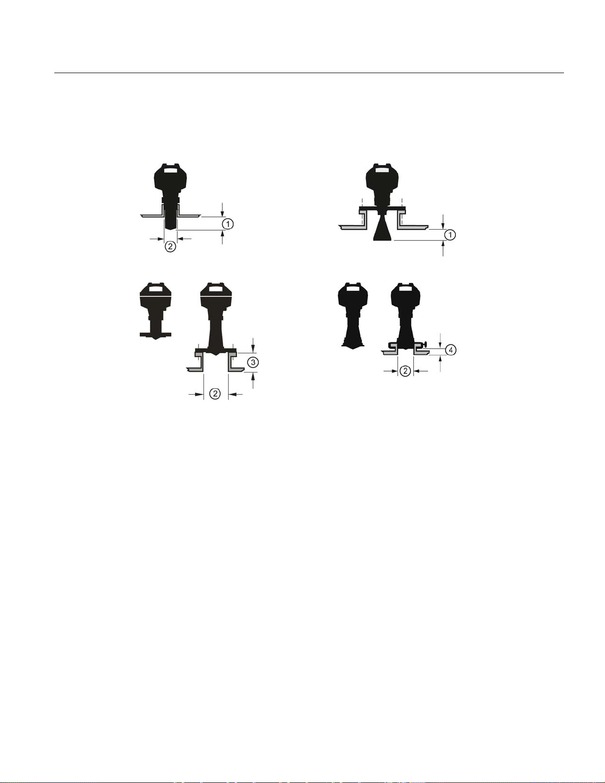
4.3.1
Nozzle design
Threaded PVDF antenna
Stainless steel horn antenna
Flanged encapsulated antenna (FEA)
Hygienic encapsulated antenna (HEA)
4.3 Proper mounting
Minimum clearance: 10 mm (0.4")
①
Minimum diameter: 50 mm (2")
②
Maximum nozzle length
③
Maximum length/diameter ratio 1:1
④
● The end of the antenna must protrude a minimum of 10 mm (0.4") to avoid false echoes
being reflected from the nozzle
● Minimum recommended nozzle diameter for the threaded PVDF antenna is 50 mm (2").
● An antenna extension (100 mm/3.93") is available for the horn antenna only.
1)
.
● The maximum nozzle length for the FEA is 500 mm (19.68") when the nozzle diameter is
DN150 (6"). Only shorter lengths are recommended for smaller diameters.
● When installing the SITRANS LR250 with hygienic process connection, it is good hygienic
practice to install the antenna in a nozzle that has a maximum length/diameter ratio of 1:1.
For example, 2" (DN50) diameter nozzle should be no longer than 2" (50 mm).
● When removing any sanitary/hygienic clamp version of the HEA to clean the lens, ensure it is
re-installed in the exact position it was removed from, to avoid re-commissioning the device.
1)
Not applicable for FEA or HEA
SITRANS LR250 (FOUNDATION FIELDBUS)
Operating Instructions, 08/2014, A5E32221411-AC
27
Installing/mounting
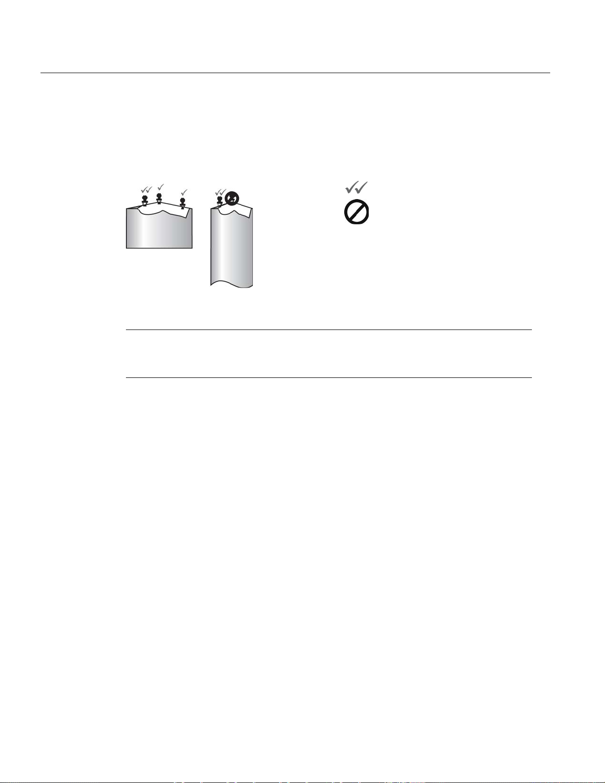
4.3.2
Nozzle location
Beam angle
Note
4.3 Proper mounting
● Avoid central locations on tall, narrow vessels
● Nozzle must be vertical and clear of imperfections
Preferred
Undesirable
• Beam width depends on antenna size and is approximate: see below.
• For details on avoiding false echoes, see Auto False Echo Suppression (Page 271).
● Beam angle is the width of the cone where the energy density is half of the peak energy
density.
● The peak energy density is directly in front of and in line with the antenna.
● There is a signal transmitted outside the beam angle, therefore false targets may be
detected.
SITRANS LR250 (FOUNDATION FIELDBUS)
28 Operating Instructions, 08/2014, A5E32221411-AC
Installing/mounting
Horn antenna
Flanged encapsulated antenna
Threaded PVDF antenna
Hygienic encapsulated antenna
4.3 Proper mounting
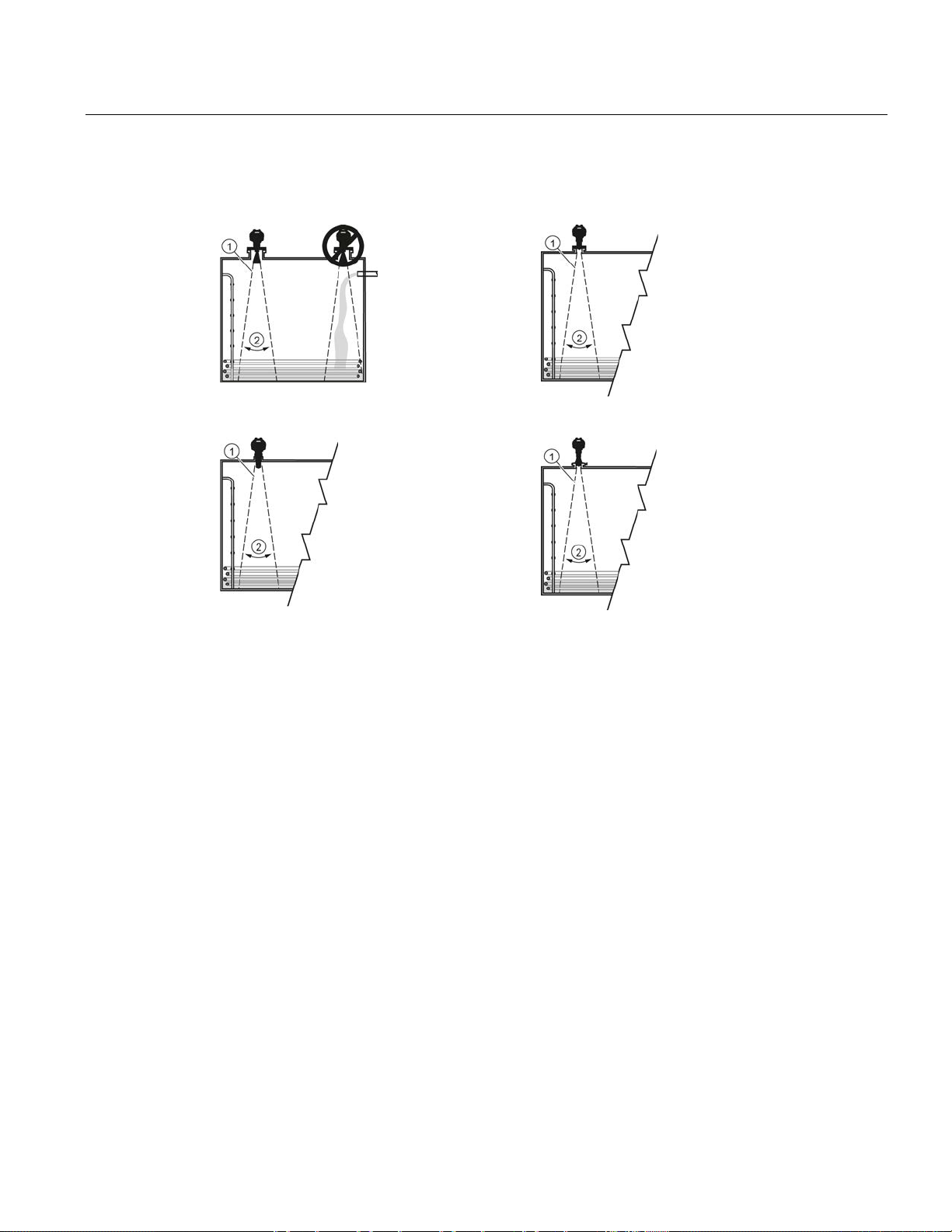
①
②
Emission cone
Beam angle
SITRANS LR250 (FOUNDATION FIELDBUS)
Operating Instructions, 08/2014, A5E32221411-AC
29

Installing/mounting
Emission cone type and beam angle
Antenna type
Antenna size
Beam angle
Process connection
size
Process connection type
Emission cone
Access for programming
4.3 Proper mounting
Horn 1.5" 19°
2" 15°
3" 10°
4" 8°
Threaded PVDF 19°
Flanged encapsulated 2" Class 150 ASME B16.5 12.8°
3, 4, 6" Class 150 ASME B16.5 9.6°
50A 10K JIS B 2220 12.8°
80A/100A/150A 10K JIS B 2220 9.6°
DN50 PN10/16 EN1092-1 12.8°
DN80/DN100/DN150 PN10/16 EN1092-1 9.6°
Hygienic encapsulated 2" Sanitary Clamp according to
3, 4" 9.6°
DN50 Aseptic/Hygienic nozzle/slotted
DN80/DN100 9.6°
DN50 Aseptic/Hygienic flanged
DN80/DN100 9.6°
DN50 Aseptic/Hygienic Clamp
DN80/DN100 9.6°
DN50 Hygienic nozzle/slotted nut
DN80/DN100 9.6°
Type F (50 mm)
and Type N
(68 mm)
ISO 2852
nut according to DIN 11864-1
[Form A]
according to DIN 11864-2
[Form A]
according to DIN 118643 [Form A]
according to DIN 11851
Tuchenhagen Varivent 12.8°
12.8°
12.8°
12.8°
12.8°
12.8°
● Keep emission cone free of interference from obstructions such as ladders, pipes, I-beams,
or filling streams.
● Provide easy access for viewing the display and programming via the handheld programmer.
SITRANS LR250 (FOUNDATION FIELDBUS)
30 Operating Instructions, 08/2014, A5E32221411-AC
 Loading...