

Siemens SITRANS LR25 Quick Start Manual
Radar Transmitters
SITRANS LR250 (Foundation Fieldbus)
Quick Start Manual 01/2012
SITRANS

SITRANS LR250 (Foundation Fieldbus)
Quick Start Manual
This manual outlines the essential features and functions of the SITRANS LR250 (Foundation
Fieldbus). We strongly advise you to acquire the detailed version of the manual so you can use
your instrument to its fullest potential. The complete manual can be downloaded from the
product page of our web site at: www.siemens.com/LR250
your local Siemens representative.
Questions about the contents of this manual can be directed to:
Siemens AG
Siemens Milltronics Process Instruments
1954 Technology Drive, P.O. Box 4225
Peterborough, Ontario, Canada, K9J 7B1
Email: techpubs.smpi@siemens.com
. The printed manual is available from
English
Copyright Siemens AG 2011.
All Rights Reserved
We encourage users to purchase authorized bound manuals, or to view electronic versions as designed and
authored by Siemens Milltronics Process
Instruments Inc. Siemens Milltronics
Process Instruments Inc. will not be
responsible for the contents of partial or
whole reproductions of either bound or
electronic versions.
MILLTRONICS® is a registered trademark of Siemens Milltronics Process Instruments Inc .
While we have verified the contents of this manual
for agreement with the instrumentation described,
variations remain possible. Thus we cannot guarantee full agreement. The contents of this manual
are regularly reviewed and corrections are
included in subsequent editions. We welcome all
suggestions for improvement.
Technical data subject to change.
Disclaimer of Liability
Technical Support
Support is available 24 hours a day.
To find your local Siemens Automation Office address, phone number and fax number go to:
www.siemens.com/automation/partner:
• Click on the tab Contact, select Service, then click Service again to find your product
group (+Automation Technology > +Sensor Systems >+Process Instrumentation > +Level
Measurement > +Continuous). Select Radar.
• Select the country followed by the City/Region.
• Select Technical Support under Service.
For on-line technical support go to: www.siemens.com/automation/support-request
• Enter the instrument name (SITRANS LR250) or order number, then click on Search, and
select the appropriate product type. Click on Next.
• Enter a keyword describing your issue. Click on Next. Then either browse the relevant
documentation, or click on Next to E-mail a description of your issue to Siemens
Technical Support staff.
Siemens IA/DT Technical Support Center: phone +49 (0)911 895 7222
7ML19985XN82 SITRANS LR250 (FF) – QUICK START MANUAL Page EN-1

Safety Guidelines
Warning notices must be observed to ensure personal safety as well as that of others, and to
protect the product and the connected equipment. These warning notices are accompanied by
a clarification of the level of caution to be observed.
1)
English
WARNING: relates to a caution symbol on the product, and means that failure to
observe the necessary precautions can result in death, serious injury, and/or
considerable material damage.
WARNING
in death, serious injury, and/or considerable material damage.
1
: means that failure to observe the necessary precautions can result
Note: means important information about the product or that part of the operating manual.
FCC Conformity
US Installations only: Federal Communications Commission (FCC) rules
WARNING: Changes or modifications not expressly approved by Siemens
Milltronics could void the user’s authority to operate the equipment.
Notes:
• This equipment has been tested and found to comply with the limits for a Class A digital
device, pursuant to Part 15 of the FCC Rules. These limits are designed to provide
reasonable protection against harmful interference when the equipment is operated in a
commercial environment.
• This equipment generates, uses, and can radiate radio frequency energy and, if not
installed and used in accordance with the instruction manual, may cause harmful
interference to radio communications. Operation of this equipment in a residential area is
likely to cause harmful interference to radio communications, in which case the user will
be required to correct the interference at his own expense.
SITRANS LR250
WARNING: SITRANS LR250 is to be used only in the manner outlined in this manual,
otherwise protection provided by the equipment may be impaired.
Note: This product is intended for use in industrial areas. Operation of this equipment in a
residential area may cause interference to several frequency based communications.
SITRANS LR250 is a 2-wire 25 GHz pulse radar level transmitter for continuous monitoring of
liquids and slurries in storage vessels including high pressure and high temperature, to a range
of 20 m (66 ft). It is ideal for small vessels and low dielectric media.
The instrument consists of an electronic component coupled to a horn antenna and either a
threaded or flange type process connection. A threaded PVDF antenna is also available.
SITRANS LR250 supports Foundation Fieldbus (FF) communication protocol. Signals are
processed using Process Intelligence which has been field-proven in over 1,000,000
applications worldwide (ultrasonic and radar). This instrument can be configured as an FF (H1)
Link Master.
1)
This symbol is used when there is no corresponding caution symbol on the product.
Page EN-2 SITRANS LR250 (FF) – QUICK START MANUAL 7ML19985XN82

Specifications
standard horn antenna:
- with FKM O-ring: –40
o
C to +200 oC (–40 oF to +392 oF)
- with FFKM O-ring: –20
o
C to +200 oC (–4 oF to +392 oF)
2" NPT / BSPT / G Threaded PVDF antenna:
−40 to +80 °C (−40 to +176 °F)
ambient temperature
(surrounding enclosure)
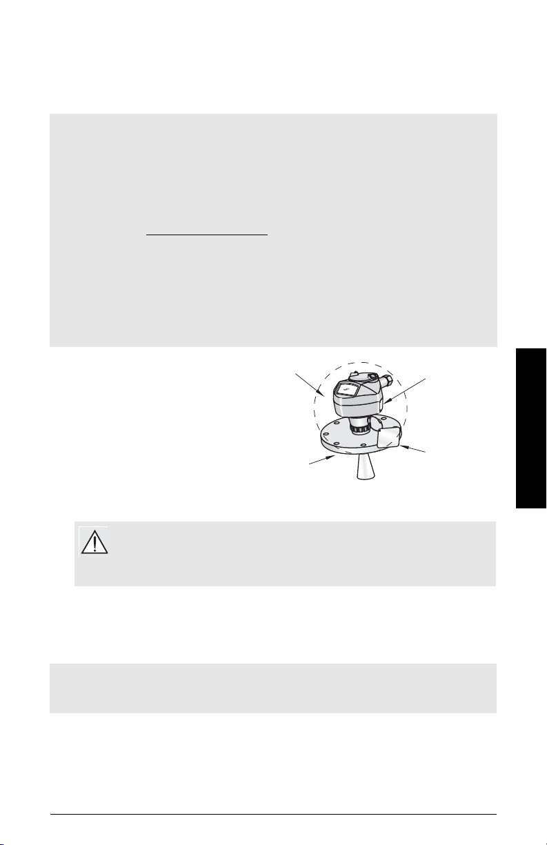
–40 °C to 80 °C (–40 °F to 176 °F)
device
nameplate
process
connection
tag
For a complete listing, see the SITRANS LR250 (FF) Operating Instructions manual. For
Approvals information, please refer to the process device tag.
Ambient/Operating Temperature
Notes:
• The maximum temperature is dependent on the process connection, antenna materials,
and vessel pressure: see
more detailed information see Process Pressure/Temperature derating curves in the full
manual.
• Process temperature and pressure capabilities are dependent upon information on the
process connection tag. The reference drawing listed on the tag is available on the
product page of our website at www.siemens.com/LR250
drawings/Level Measurement/Installation Drawings/LR250. Additional information on
process connections is available on the Installation Drawings page under Process
Connection Diagrams.
• Signal amplitude increases with antenna diameter, so use the largest practical size.
• Optional extensions can be installed below the threads.
• See
Maximum Process Temperature Chart
Wiring Setups for hazardous area installations
, under More Info/Installation
on page 24, for more details.
on page 9. For
English
Power
General Purpose:
Intrinsically Safe:
Non-Sparking/Energy Limited:
9-32 V DC
Non-incendive:
• Bus powered 9-32 V DC, per IEC 61158-2 (Foundation Fieldbus)
• Current consumed: 20 mA
Approvals
Notes:
• The device nameplate lists the approvals that apply to your device.
• Use appropriate conduit seals to maintain IP or NEMA rating.
• General CSA
, CE, FM, NE 21, C-TICK, KC
US/C
• Radio FCC, Industry Canada and Europe ETSI EN 302-372
7ML19985XN82 SITRANS LR250 (FF) – QUICK START MANUAL Page EN-3

Approvals (continued)
• Hazardous
Intrinsically Safe
(Europe) ATEX II 1G, Ex ia IIC T4 Ga
(International) IECEx SIR 09.0148X, Ex ia IIC T4 Ga
English
(US/Canada) FM/CSA
(Brazil) INMETRO TUV 11.0309 X, Ex ia IIC T4 Ga
(China) NEPSI Ex ia IIC T4/ DIP A20 T
Non-sparking/Energy Limited
(Europe) ATEX II 3G, Ex nA/nL IIC T4 Gc
(China) NEPSI Ex nA II T4/ Ex nL IIC T4
Non-incendive
(US/Canada) FM/CSA Class I, Div. 2, Groups A, B, C, D T5
• Marine Lloyd’s Register of Shipping
ABS Type Approval
1)
3)
Bureau Veritas
ATEX II 1D, Ex tD A20 IP67 T90 °C Da
Ex tD A20 IP67 T90 °C Da
Class I, Div. 1, Groups A, B, C, D
Class II, Div. 1, Groups E, F, G
Class III T4
Ex ia IIIC T90 ºC Da IP65/IP67
TUV #: OCP 0004
2)
A,
Pressure Application
WARNINGS:
• Never attempt to loosen, remove, or disassemble process connection or
instrument housing while vessel contents are under pressure.
• The user is responsible for the selection of bolting and gasket materials which
will fall within the limits of the flange and its intended use and which are suitable
for the service conditions.
• Improper installation may result in loss of process pressure.
Notes:
• The process connection tag shall remain with the process pressure boundary assembly
In the event the instrument package is replaced, the process connection tag shall be
transferred to the replacement unit.
• SITRANS LR250 units are hydrostatically tested, meeting or exceeding the requirements
of the ASME Boiler and Pressure Vessel Code and the European Pressure Equipment
Directive.
4)
T90 oC IP6X
1)
.
1)
See
Intrinsically Safe wiring1.
2)
See
Non-Sparking/Energy Limited wiring2.
3)
See
Non-incendive wiring (only for USA/Canada)3.
4)
The process pressure boundary assembly comprises the components that act as a barrier against
pressure loss from the process vessel: that is, the combination of process connection body and
emitter, but normally excluding the electrical enclosure.
on page 11
on page 12.
on page 13.
Page EN-4 SITRANS LR250 (FF) – QUICK START MANUAL 7ML19985XN82

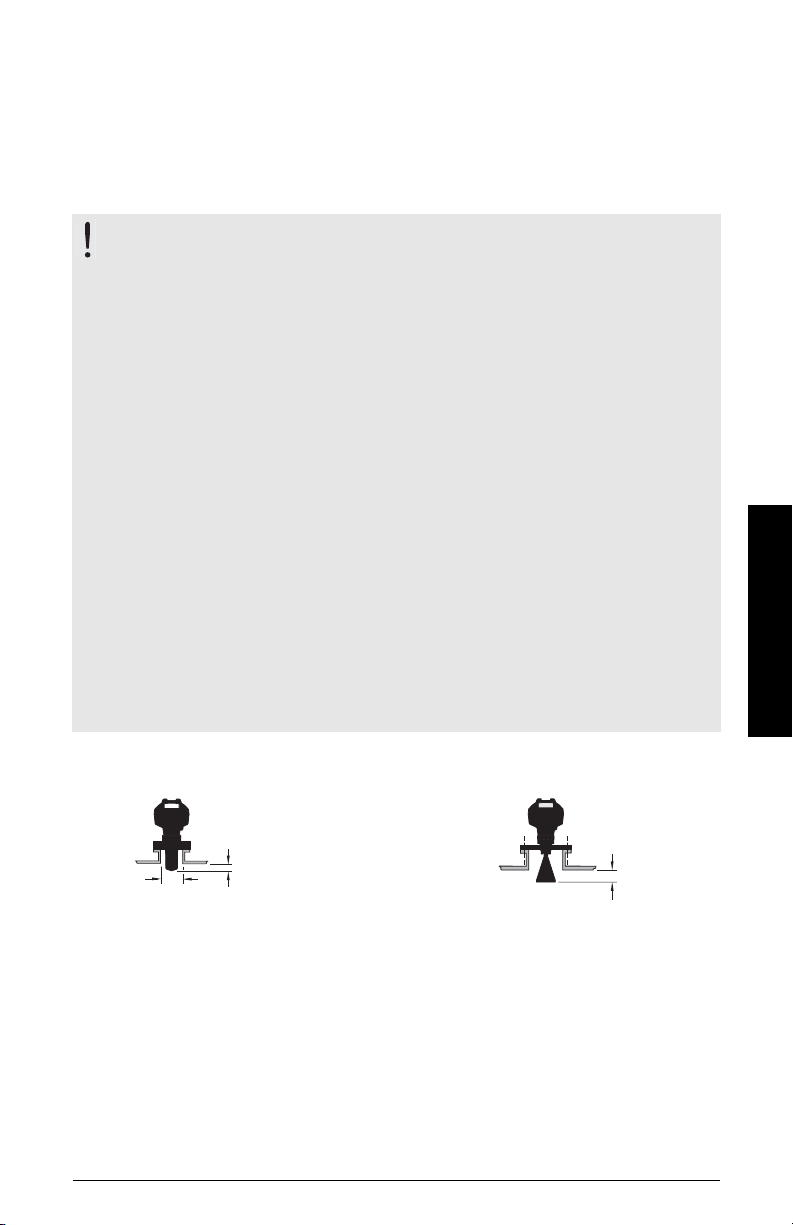
Pressure Equipment Directive, PED, 97/23/EC
min. clearance:
10 mm (0.4")
Threaded PVDF Antenna Stainless Steel Horn Antenna
Min. dia. 50 mm (2")
min. clearance:
10 mm (0.4")
Siemens Level Transmitters with flanged, threaded, or sanitary clamp type process mounts
have no pressure-bearing housing of their own, and therefore do not come under the Pressure
Equipment Directive as pressure or safety accessories (see EU Commission Guideline 1/8 and
1/20).
Installation
WARNINGS:
• Installation shall be performed only by qualified personnel and in
accordance with local governing regulations.
• Handle the device using the enclosure, not the antenna or the process
connection tag, to avoid damage.
• Take special care when handling the threaded PVDF antenna. Any damage
to the antenna surface, particularly to the tip, could affect performance.
• Materials of construction are chosen based on their chemical compatibility
(or inertness) for general purposes. For exposure to specific environments,
check with chemical compatibility charts before installing.
Notes:
• For European Union and member countries, installation must be according to ETSI EN
302372.
• Refer to the device nameplate for approval information.
• The serial numbers stamped in each process connection body provide a unique
identification number indicating date of manufacture.
Example: MMDDYY – XXX (where MM = month, DD = day, YY = year, and XXX= sequential
unit produced)
• Further markings (space permitting) indicate flange configuration, size, pressure class,
material, and material heat code.
English
Nozzle design
• The end of the antenna must protrude a minimum of 10 mm (0.4”) to avoid false echoes
being reflected from the nozzle.
• Minimum recommended nozzle diameter for the threaded PVDF antenna is 51 mm (2").
• An antenna extension (100 mm/ 3.93") is available for any version except the threaded
PVDF antenna.
7ML19985XN82 SITRANS LR250 (FF) – QUICK START MANUAL Page EN-5
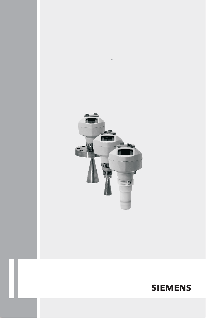
Nozzle location
preferred
undesirable
beam angle:
threaded PVDF
antenna = 19°
1.5" horn = 19°
2" horn = 15°
3" horn = 10°
4" horn = 8°
beam
angle
emission
cone
Avoid central locations on tall, narrow vessels.
Environment
• Provide an environment suitable to the housing
rating and materials of construction.
English
• Provide a sunshield if the device will be mounted
in direct sunlight.
Beam angle
• Beam angle is the width of the cone
where the energy density is half of the
peak energy density.
• Peak energy density is directly in front
of and in line with the antenna.
• Signal is transmitted outside the beam
angle; therefore false targets may be
detected.
Emission Cone
• Keep emission cone free of interference
from ladders, pipes, I-beams or filling
streams.
Access for programming
• Provide easy access for viewing the display and programming via the handheld
programmer
Mounting instructions
WARNING: For pressure applications use PTFE tape or other appropriate thread
sealing compound and tighten the process connection beyond hand-tight. The
maximum recommended torque is 40 N-m (30 ft.lbs.)
Note:
• There is no limit to the number of times an instrument can be rotated without damage.
• When mounting, orient the front or back of the instrument towards the closest wall.
• Do not rotate the enclosure after programming and vessel calibration, otherwise an error
may occur, caused by a polarity shift of the transmit pulse.
Threaded Versions
1) Before inserting the instrument into its mounting connection, check to ensure the threads
are matching to avoid damaging them.
2) Simply screw the instrument into the process connection, and hand tighten, or use a
wrench. For pressure applications see Warning note above.
Flanged Versions
WARNING: The user is responsible for the selection of bolting and gasket materials
which will fall within the limits of the flange and its intended use, and which are
suitable for the service conditions.
Page EN-6 SITRANS LR250 (FF) – QUICK START MANUAL 7ML19985XN82
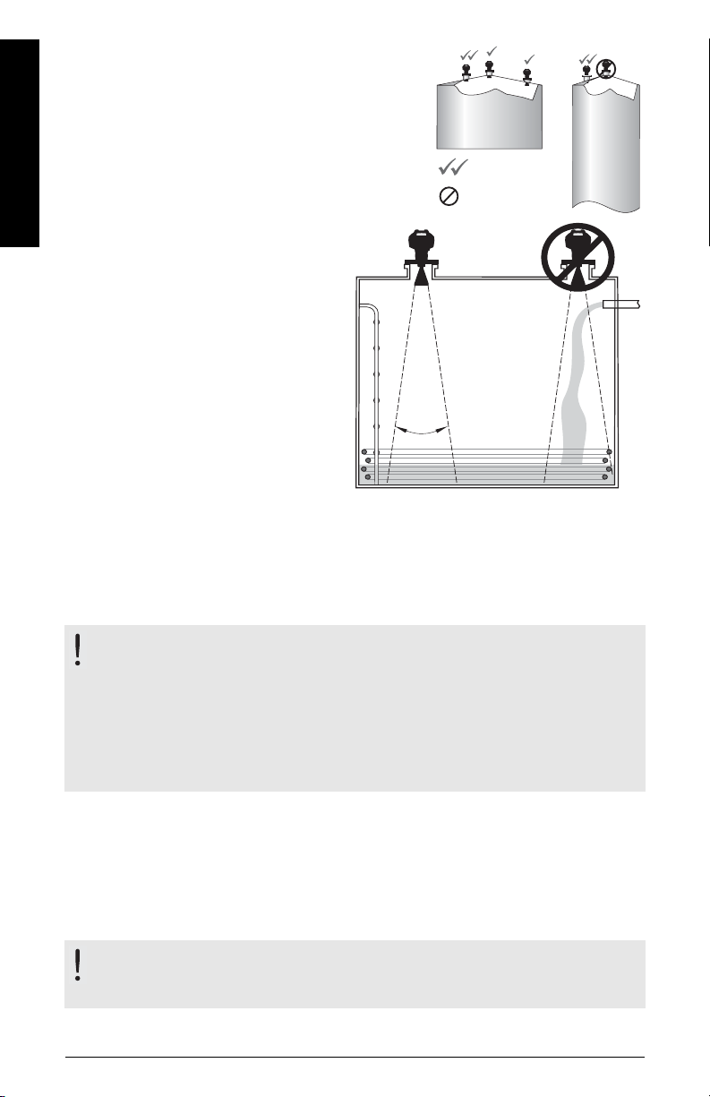
Wiring
cable shield
device shield
connection
1)
external
ground lug
plug (IP 68)
optional cable gland
2) 3)
(or NPT cable entry
3)
)
Use a 2 mm Allen key to
loosen the lid-lock set
screw.
Power
WARNINGS:
The DC input terminals shall be supplied from a source providing electrical
isolation between the input and output, in order to meet the applicable safety
requirements of IEC 61010-1.
All field wiring must have insulation suitable for rated voltages.
Connecting SITRANS LR250
1) 2)
WARNINGS:
• Check the device nameplate to verify the approval rating.
• Use appropriate conduit seals to maintain IP or NEMA rating.
• See
Wiring Setups for hazardous area installations
For detailed wiring instructions refer to the full LR250 FF Operating Instructions.
Note:
on page 9.
English
1) Strip the cable jacket for approximately 70 mm (2.75") from the end of the Foundation
Fieldbus cable, and thread the wires through the gland
3)
.
2) Connect the wires to the terminal as shown (SITRANS LR250 FF is not polarity sensitive).
3) Ground the instrument according to local regulations.
4)
4) Tighten the gland to form a good seal.
5) Close the lid and secure the locking ring before programming and instrument
configuration.
(continued on next page)
1)
The device shield connection is internally connected to the external ground lug.
2)
May be shipped with the instrument.
3)
If cable is routed through conduit, use only approved suitable-size hubs for waterproof applications.
4)
7ML19985XN82 SITRANS LR250 (FF) – QUICK START MANUAL Page EN-7
For optimum EMC protection, it is recommended that the FF H1 cable shield be connected to ground at
every node.
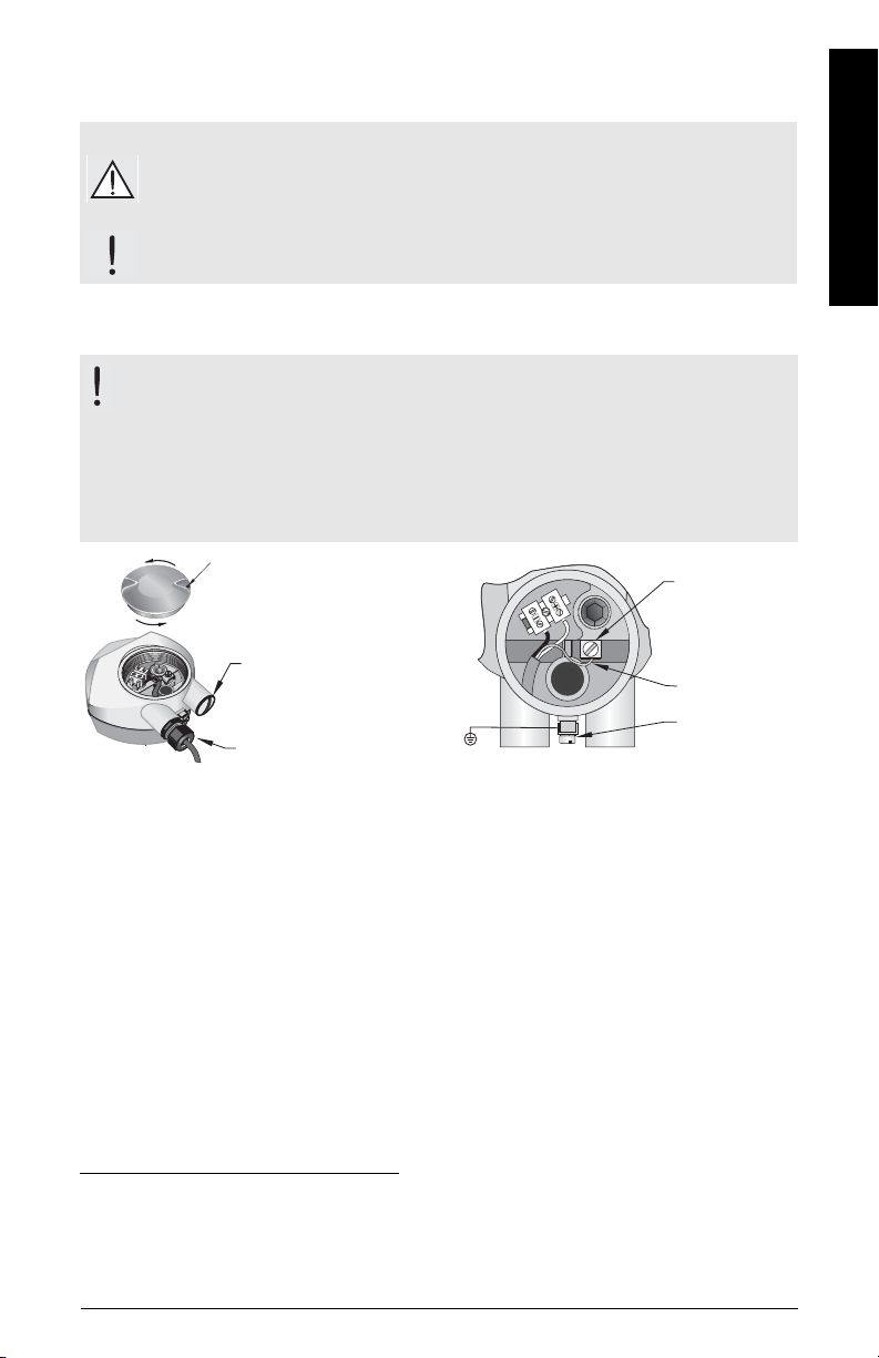
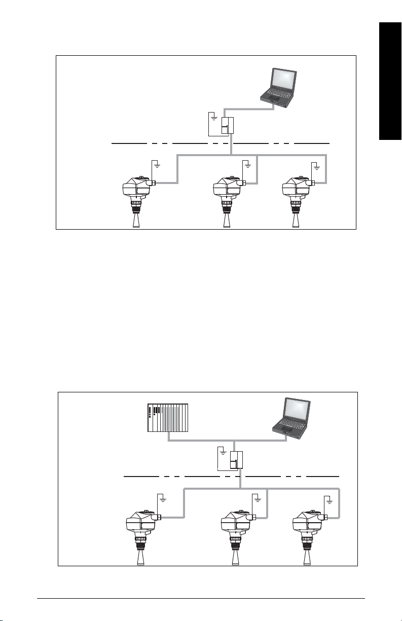
Notes:
controller
Rosemount
3420 HSE/H1
Gateway
configurator
software
LR250 FF
LR250 FF LR250 FF
PC/laptop
FF (H1)
controller
HSE/H1
Linking Device
LR250 FF
LR250 FF
LR250 FF
PC/laptop
FF (H1)
Configuration via
Gateway
Configuration via
Linking Device
FF (HSE)
FF (HSE)
Basic Configuration cont’d on next page.
configurator
software
• Foundation Fieldbus (H1) must be terminated at both extreme ends of the cable for it to
work properly.
• Please refer to the
2.0
, available from www.fieldbus.org, for information on installing FF (H1) devices.
English
Basic Configuration with Foundation Fieldbus (H1)
Foundation Fieldbus System Engineering Guidelines (AG-181) Revision
Page EN-8 SITRANS LR250 (FF) – QUICK START MANUAL 7ML19985XN82
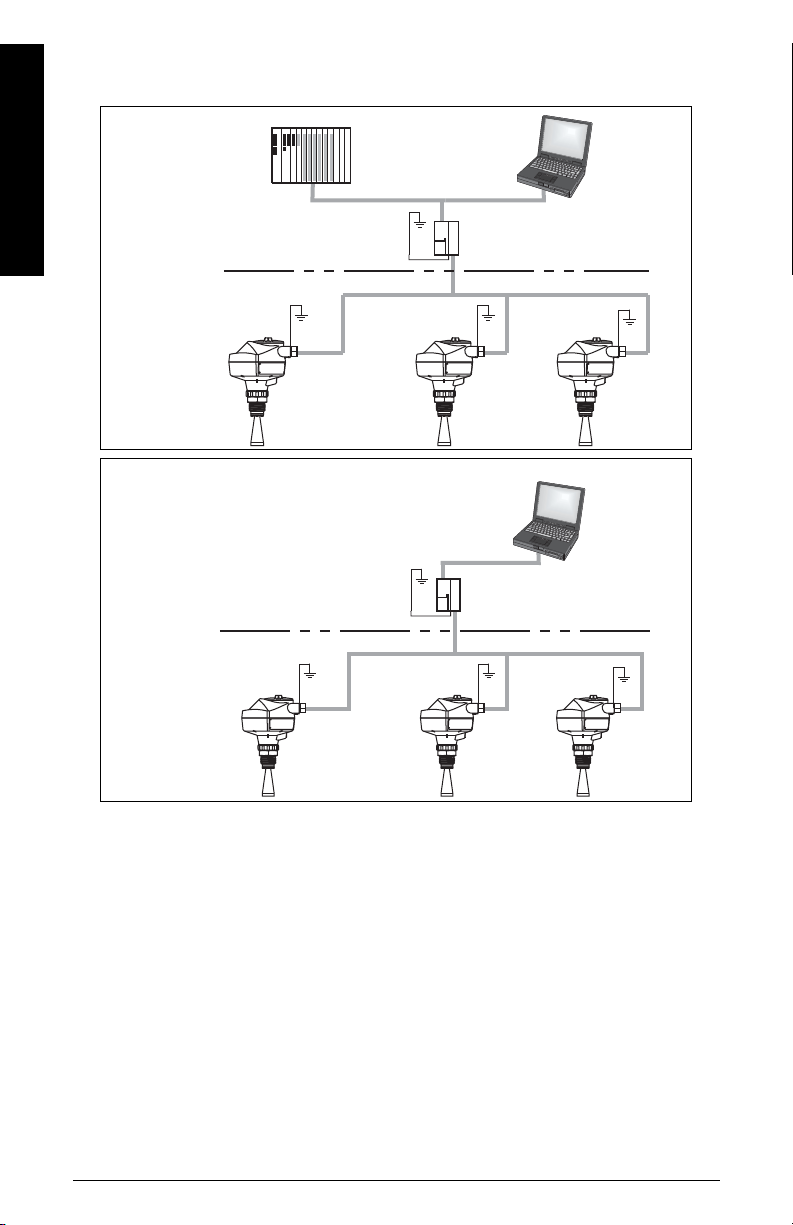
Wiring Setups for hazardous area installations
H1 Interface
LR250 FF
LR250 FF LR250 FF
PC/laptop
FF (H1)
Configuration via
PCI/PCMCIA Card
PCI/PCMCIA bus
Basic Configuration cont’d.
configurator
software
Hazardous Area
Non-hazardous Area
controller
EEx ia type
HSE/H1
LR250 FF
LR250 FF
LR250 FF
PC/laptop
FF (H1)
Configuration via
Gateway
FF (HSE)
configurator
software
There are three wiring options for hazardous area installations:
•
Intrinsically Safe wiring
Non-Sparking/Energy Limited wiring
•
Non-incendive wiring (only for USA/Canada)
•
In all cases, check the device nameplate and process connection tag to verify the approval
rating.
on page 11
on page 12
on page 13.
English
Configuration with Foundation Fieldbus for hazardous
areas
7ML19985XN82 SITRANS LR250 (FF) – QUICK START MANUAL Page EN-9
English
Hazardous Area
Non-hazardous Area
controller
EEx ia type
HSE/H1
Linking Device
LR250 FF
LR250 FF
LR250 FF
PC/laptop
FF (H1)
Configuration via
Linking Device
Hazardous Area
Non-hazardous Area
EEx ia type
H1 Interface
LR250 FF
LR250 FF LR250 F F
PC/laptop
FF (H1)
Configuration via
PCI/PCMCIA Card
FF (HSE)
PCI/PCMCIA bus
Configuration for hazardous areas continued
configurator
software
configurator
software
Page EN-10 SITRANS LR250 (FF) – QUICK START MANUAL 7ML19985XN82
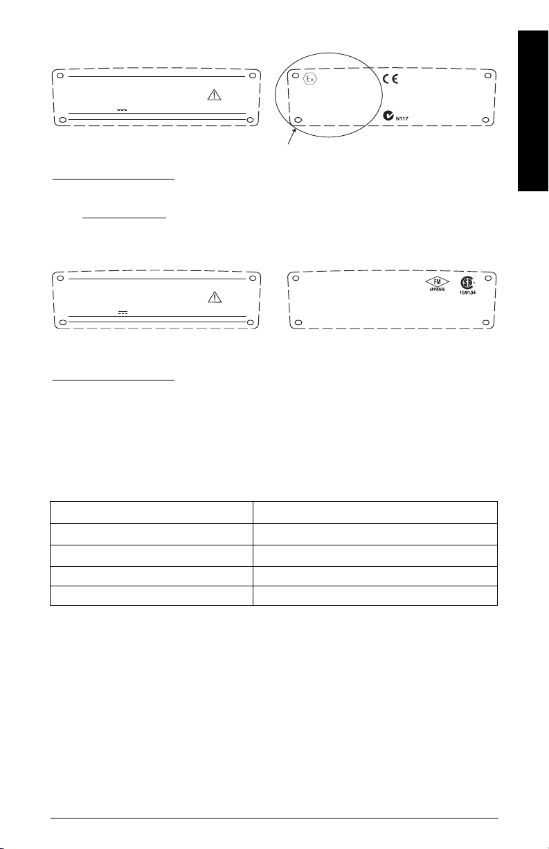
1.Intrinsically Safe wiring
1 G D EEx ia IIC T4
Ex tD A20 IP67 T90 °C
II
SIRA 09ATEX2353X
Fisco:
Ui = 17.5 V
Ii = 380 mA
Pi = 5.32 W
Ci=0nF
Li=0mH
Entity:
Ui=24V
Ii = 250 mA
Pi = 1.2 W
Ci=0nF
Li=0mH
IECEx SIR 09.0148X
Ex ia IIC T4
Ex tD A20 IP67 T90 °C
0518
SITRANS LR250
Made in Canada
Siemens Milltronics Process Instruments Inc., Peterborough
7MLxxxx-xxxxx-xxxx
Encl.: NEMA / TYPE 4X, 6, IP67, IP68
Amb.Temp.:– 40 °C to 80 °C
Power Rating: 32 V
Max., 20 mA
Serial No: GYZ / A1034567
s
FOUNDATIONFIELDBUS
The ATEX certificates listed on the nameplate
can be downloaded from the product page of our website at:
www.siemens.com/LR250
. Go to More Info > Certificates.
Device nameplate (ATEX/IECEx/C-TICK)
The IECEx certificate listed on the nameplate can be viewed on the IECEx website.
Go to: http://iecex.iec.ch
> Ex Equipment Certificates of Conformity and enter the certificate
number IECEx SIR 09.0148X.
Exia per drawing: A5E02358161
R
Fisco:
Ui = 17.5 V
Ii = 380 mA
Pi = 5.32 W
Ci=0nF
Li=0mH
Entity:
Ui=24V
Ii = 250 mA
Pi = 1.2 W
Ci=0nF
Li=0mH
Class I, Div 1, Gr.A, B,C, D
Class II, Div 1, Gr.E, F, G
Class III T4
This device complies with Part 15 of the FCC Rules. Operation is subject to the followingtwo
conditions 1)This device may notcause harmful interference and 2)This device must accept
any interferencereceived, including interference that may cause undesired operation
IC: 267P-LR250
FCC ID: NJA-LR250
SITRANS LR250
Made in Canada
Siemens Milltronics Process Instruments Inc., Peterborough
7MLxxxx-xxxxx-xxxx
Encl.: NEMA / TYPE 4X, 6, IP67, IP68
Amb.Temp.:– 40 °C to 80 °C
Power Rating: 32 V
Max., 20 mA
Serial No: GYZ / A1034567
s
FOUNDATIONFIELDBUS
The FM/CSA Intrinsically Safe connection drawing
number A5E02358161 can be downloaded from the product page of our website at:
www.siemens.com/LR250
.
Go to More Info > Installation Drawings > Level Measurement > SITRANS LR250.
Device nameplate (FM/CSA)
• For wiring requirements: follow local regulations.
• Approved dust-tight and water-tight conduit seals are required for outdoor NEMA 4X /
type 4X / NEMA 6, IP67, IP68 locations.
• Refer to
Instructions specific to hazardous area installations
on page 13.
English
Under the entity evaluation concept, SITRANS LR250 has the following characteristics:
(input voltage) U
(input current) I
(input power) P
i
= 250 mA
i
i
= 24 V
= 1.2 W
(internal capacitance) Ci = 0
(internal inductance) Li = 0
Entity Concept:
The Entity Concept allows interconnection of Intrinsically Safe apparatus to associated
apparatus not specifically examined in such combination. The criteria for interconnection is
that the voltage and current which Intrinsically Safe apparatus can receive and remain
Intrinsically Safe, considering faults, must be equal to or greater than the output voltage (Uo)
and output current (Io) levels which can be delivered by the associated apparatus, considering
faults and applicable factors. In addition, the maximum unprotected capacitance (Ci) and
Inductance (Li) of the Intrinsically Safe apparatus, including interconnecting wiring, must be
equal to or less than the capacitance and inductance which can be safely connected to
associated apparatus.
7ML19985XN82 SITRANS LR250 (FF) – QUICK START MANUAL Page EN-11
FISCO Concept
SITRANS LR250
Made in Canada
Siemens Milltronics Process Instruments Inc., Peterborough
7MLxxxx-xxxxx-xxxx
Encl.: NEMA / TYPE 4X, 6, IP67, IP68
Amb.Temp.: – 40 °C to80 °C
Power Rating: 32 V
Max., 20 mA
Serial No: GYZ / A1034567
Warning:
Potential Electrostatic ChargingHazard Do Not Clean
Probe With A Dry Cloth.
Do Not Install Where Build-Up Of Charge Is Likely.
Use Cable Rated > 90°C
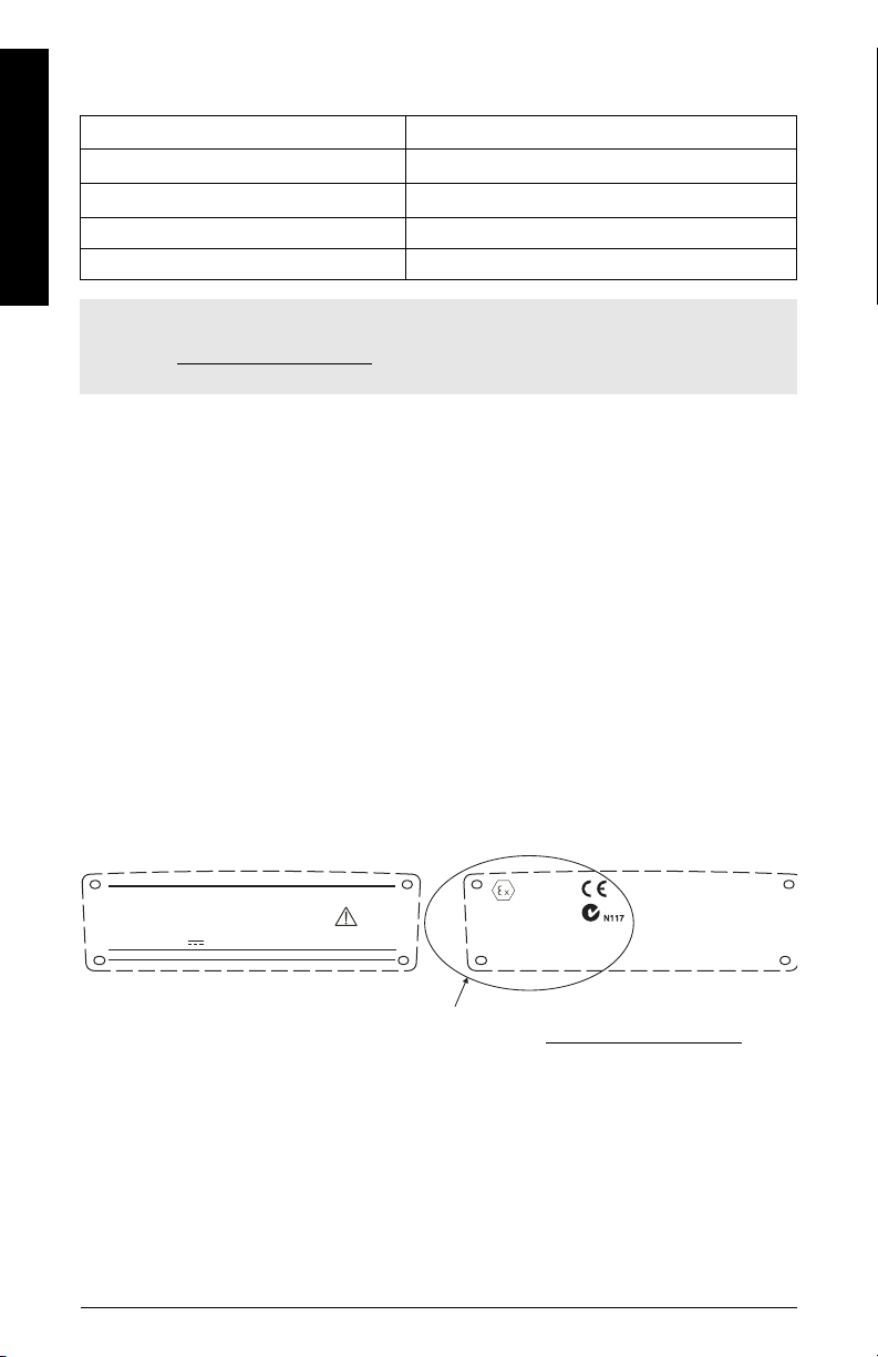
3GII
SIRA 09ATEX4354X
EEx nL IIC T4 Gc
FNICO:
Ui = 17.5 V
Ii = 570 mA
Pi = 7.98 W
Ci<5nF
Li<20µH
Entity:
Ui=32V
Ci<5nF
Li<20µH
EEx nA II T4 Gc
Un=32V
s
FOUNDATIONFIELDBUS
The ATEX certificate listed on the nameplate
can be downloaded from the product page of our website at: www.siemens.com/LR250
.
Go to More Info > Installation Drawings > Level Measurement > SITRANS LR250.
Under the FISCO evaluation concept, SITRANS LR250 has the following characteristics:
(input voltage) U
(input current) I
(input power) P
English
i
= 380 mA
i
i
(internal capacitance) Ci = 0
(internal inductance) Li = 0
Note: For complete details and instructions regarding the FISCO Concept The FM/CSA
connection drawing number A5E02358161 can be downloaded from the product page of our
website at: www.siemens.com/LR250
Measurement > SITRANS LR250.
The FISCO Concept allows interconnection of Intrinsically Safe apparatus to associated
apparatus not specifically examined in such combination. The criteria for interconnection is
that the voltage (Ui or Vmax), the current (Ii, or Imax) and the power (Pi, or Pmax) which
Intrinsically Safe apparatus can receive and remain Intrinsically Safe, considering faults, must
be equal to or greater than the voltage (Uo or Voc or Vi), the current (lo or Isc or li), and the
power (Po or Pmax) levels which can be delivered by the associated apparatus, considering
faults and applicable factors. In addition, the maximum unprotected capacitance (Ci) and
inductance (Li) of each apparatus (other than the termination) connected to the fieldbus must
be less than or equal to 5 nF and 10 μH respectively.
In each segment only one active device, normally the associated apparatus, is allowed to
provide the necessary energy for the fieldbus system. The allowed voltage Uo (or Voc or Vt) of
the associated apparatus is limited to the range of 14V dc to 24V dc. All other equipment
connected to the bus cable has to be passive, meaning that they are not allowed to provide
energy to the system, except for a leakage current of 50 μA for each connected device.
Separately powered equipment needs a galvanic isolation to assure that the Intrinsically Safe
fieldbus circuit remains passive.
= 17.5 V
= 5.32 W
. Go to More Info > Installation Drawings > Level
2.Non-Sparking/Energy Limited wiring
• For wiring requirements: follow local regulations.
• Approved dust-tight and water-tight conduit seals are required for outdoor NEMA 4X /
type 4X / NEMA 6, IP67, IP68 locations.
Page EN-12 SITRANS LR250 (FF) – QUICK START MANUAL 7ML19985XN82
3.Non-incendive wiring (only for USA/Canada)
Class I, Div. 2,
Gr.A,B,C,D;
Temp. Code: T5
This device complies with Part 15 of the FCC Rules.
Operation is subject to the following two conditions
1)This device may not cause harmful interference and
2)This device must accept any interference received,
including interference that may cause undesired operation
IC: 267P-LR250
FCC ID: NJA-LR250
159134
SITRANS LR250
Made in Canada
Siemens Milltronics Process Instruments Inc., Peterborough
7MLxxxx-xxxxx-xxxx
Encl.: NEMA / TYPE 4X, 6, IP67, IP68
Amb.Temp.:–40°Cto80°C
Power Rating: 32 V
Max., 20 mA
Serial No: GYZ / A1034567
s
FOUNDATIONFIELDBUS
FM/CSA Class 1, Div 2 connection drawing number 23650673
can be downloaded from the product page of our website at: www.siemens.com/LR250
.
Go to More Info > Installation Drawings > Level Measurement > SITRANS LR250.
• For wiring requirements: follow local regulations.
• Approved dust-tight and water-tight conduit seals are required for outdoor NEMA 4X /
type 4X / NEMA 6, IP67, IP68 locations.
• Refer to
Instructions specific to hazardous area installations
below.
Instructions specific to hazardous area installations
(Reference European ATEX Directive 94/9/EC,
Annex II, 1/0/6)
The following instructions apply to equipment covered by certificate number SIRA
09ATEX2353X and 09ATEX4354X:
1) For use and assembly, refer to the main instructions.
2) The equipment is certified for use as Category 1GD equipment per SIRA 09ATEX2353X
certificate and as Category 3G per SIRA 09ATEX4354X certificate.
3) The equipment may be used with flammable gases and vapors with apparatus group IIC,
IIB and IIA and temperature classes T1, T2, T3 andT4.
4) The equipment has a degree of ingress protection of IP67 and a temperature class of
5) The equipment is certified for use in an ambient temperature range of –40
6) The equipment has not been assessed as a safety related device (as referred to by
7) Installation and inspection of this equipment shall be carried out by suitably trained
8) The equipment is non-repairable.
9) The certificate numbers have an ’X’ suffix, which indicates that special conditions for safe
o
C and may be used with flammable dusts.
T90
o
C to +80oC.
Directive 94/9/EC Annex II, clause 1.5).
personnel in accordance with the applicable code of practice (EN 60079-14 and EN 6007917 in Europe).
use apply. Those installing or inspecting this equipment must have access to the
certificates.
English
7ML19985XN82 SITRANS LR250 (FF) – QUICK START MANUAL Page EN-13

10) If the equipment is likely to come into contact with aggressive substances, then it is the
responsibility of the user to take suitable precautions that prevent it from being adversely
affected, thus ensuring that the type of protection is not compromised.
11) Aggressive substances:e.g. acidic liquids or gases that may attack metals, or solvents
that may affect polymeric materials.
English
• Suitable precautions:e.g. establishing from the material’s data sheet that it is
resistant to specific chemicals.
Programming SITRANS LR250
A Quick Start Wizard provides an easy step-by-step guide to help you configure the instrument
for a simple application.
Quick Start Wizard via the handheld programmer
• See
Quick Start Wizard via AMS Device Manager
• See
on page 19.
on page 23.
Settings can be modified locally via the Local User Interface (see
the handheld programmer
Interface (LUI) consists of an LCD display and a handheld programmer.
on page 16) or remotely via AMS Device Manager. The Local User
Accessing parameters via
Activating SITRANS LR250
Out of the box, SITRANS LR250 will not begin measurements, and all blocks will be Out of
Service until the instrument has been configured via the local user interface (LUI), or a remote
configuration tool.
Follow these steps to configure the instrument via the LUI:
• Power up the instrument
• The LCD at startup will show LANGUAGE. Edit or cancel this selection. When complete,
the instrument will show QUICK START.
• Complete the Quick Start Wizard (see
on page 19). Completing the Quick Start Wizard or writing any parameter via the LUI
causes the instrument to begin measuring.
• The Resource Block (RES) and Level Transducer Block (LTB) will move to Automatic
mode.
• AIFB 1 and AIFB 2 will remain Out of Service (as displayed on the LCD). These blocks can
only be configured and scheduled using a network configuration tool. For more details,
see System Integration in manual
(7ML19985MP01).
Quick Start Wizard via the handheld programmer
Foundation Fieldbus for Level Instruments
Page EN-14 SITRANS LR250 (FF) – QUICK START MANUAL 7ML19985XN82
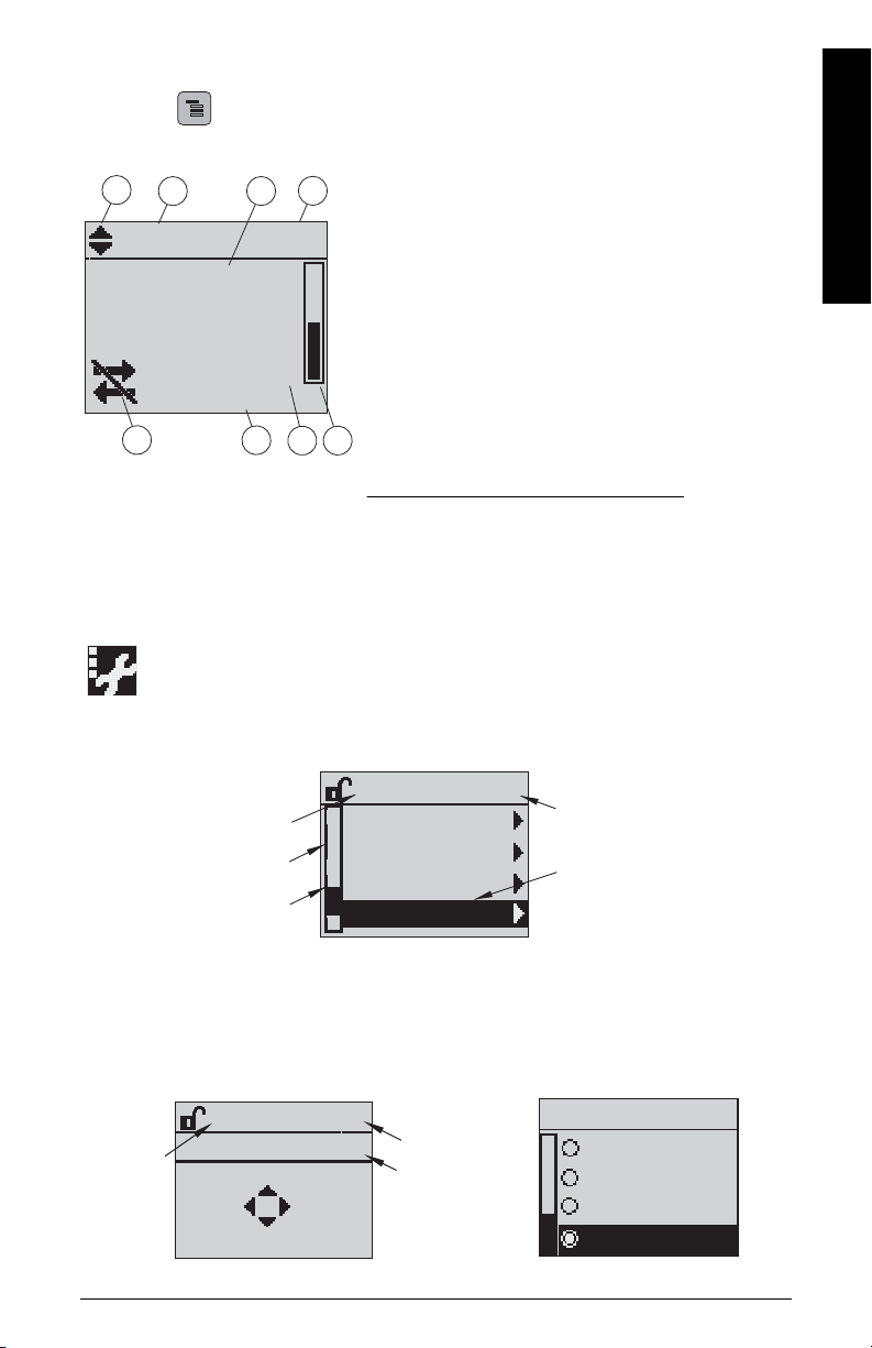
The LCD Display
M
[]
FB 1
21.40 °C
NO DATAEXCH.
18.91
1 – toggle indicator1) to switch between AIFB 1/AIFB 2
(displayed as FB 1/FB 2)
2 – identifies which block is source of displayed value
3 – measured value (level, space, distance, or volume)
4 – units
5 – bar graph indicates level
6 – secondary region indicates on request
2)
electronics
temperature, echo confidence, or distance
7 – text area displays status messages
8 – device status indicator
1)
Press UP or DOWN arrow to switch.
2)
In response to a key press request. For details, see
Quick Start Wizard via the handheld programmer
on page 19
.
678
1342
5
S: 0 LOE
7 – text area displays a fault code and an error message
8 – service required icon appears
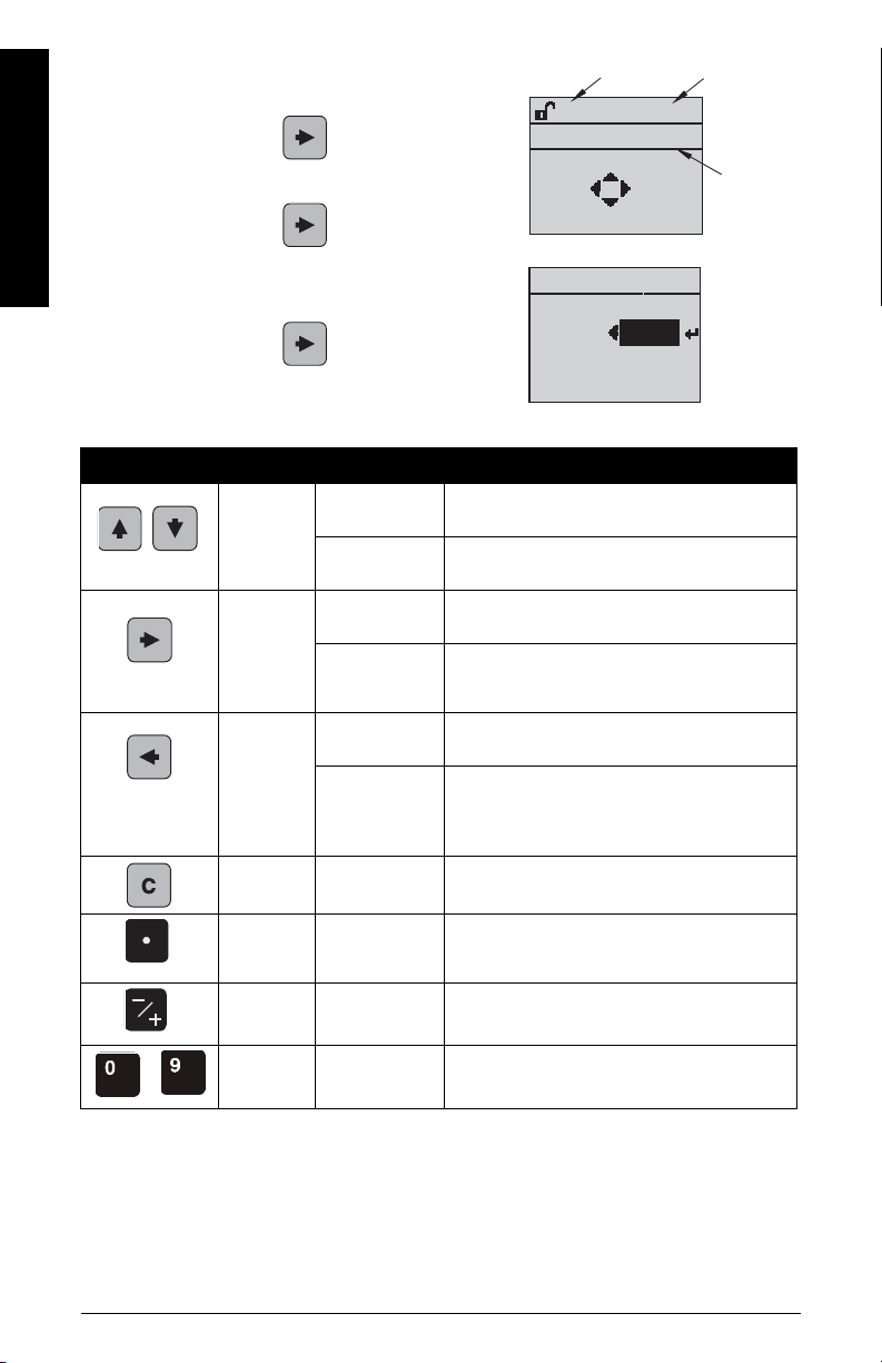
current item
number
current item
current menu
menu bar
Navigation view
item band
SIGNAL PRO..
TVT SETUP
SAMPLING
ECHO QUALITY
2.5.10
ECHO SELECT
parameter
valu e/
selection
parameter
number
parameter
name
Edit view
Parameter view
%
LEVEL UNIT
PREVIOUS
NEXT
EDITBACK
2.3.2
LEVEL UNIT
MM
FT
2.3.2
IN
%
Press Mode to toggle between Measurement and Program Mode.
Measurement mode (normal operation)
Fault present
English
PROGRAM mode display
• A visible menu bar indicates the menu list is too long to display all items.
• The depth and relative position of the item band on the menu bar indicates the length of
the menu list, and approximate position of the current item in the list.
7ML19985XN82 SITRANS LR250 (FF) – QUICK START MANUAL Page EN-15
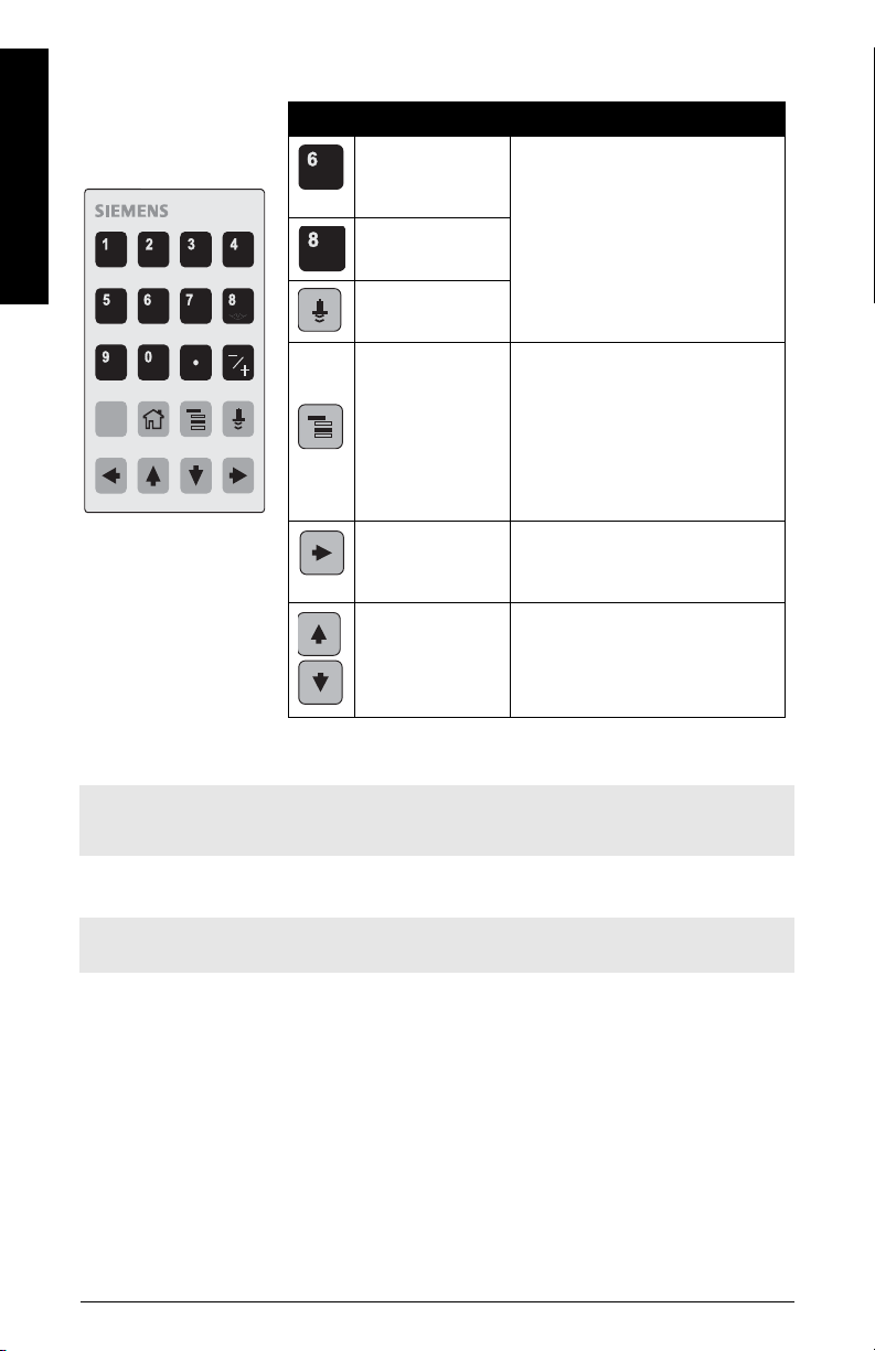
Handheld Programmer
Key Function Result
Updates internal
enclosure temperature reading.
New value is displayed in LCD
secondary region.
Updates echo
confidence value.
Updates distance
measurement.
Mode opens
PROGRAM mode–
Opens the menu level last displayed in this power cycle, unless
power has been cycled since exiting PROGRAM mode or more than
10 minutes have elapsed since
PROGRAM mode was used. Then
top level menu will be displayed.
Right ARROW
opens PROGRAM
mode–
Opens the top level menu.
Up or Down
ARROW
toggles between
AIFB 1 and AIFB 2.
Identifies which AIFB is the
source of the displayed value.
C
(Ordered separately:
Part No. 7ML1930-1BK)
1. QUICK START
2. SETUP
2.1. IDENTIFICATION
2.2. DEVICE
..................
2.4. LINEARIZATION
2.4.1. VOLUME
2.4.1.1.VESSEL SHAPE
English
Accessing parameters via the handheld programmer
Note: SITRANS LR250 automatically returns to Measurement mode after a period of
inactivity in PROGRAM mode (between 15 seconds and 10 minutes, depending on the menu
level).
Parameter menus
Note: For the complete list of parameters with instructions, see the full LR250 FF Operating
Instructions manual.
Parameters are identified by name and organized
into function groups. For the complete list of
parameters with instructions, see the full LR250 FF
Operating Instructions manual.
Page EN-16 SITRANS LR250 (FF) – QUICK START MANUAL 7ML19985XN82
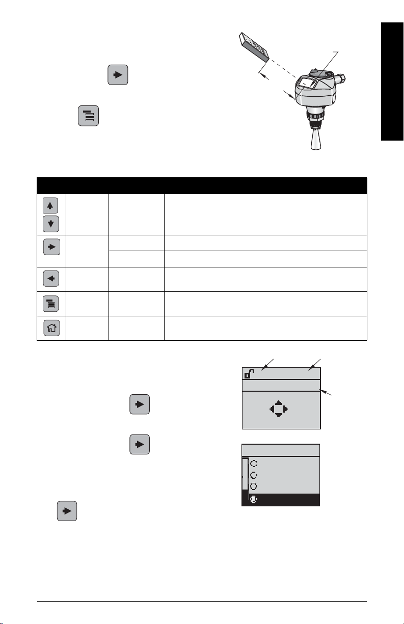
1. Enter PROGRAM mode
display
handheld programmer
Max. 300 mm
(1 ft)
parameter name
parameter
number
current
selection
%
LEVEL UNIT
PREVIOUS
NEXT
EDITBACK
2.3.2
LEVEL UNIT
MM
FT
2.3.2
IN
%
• Point the programmer at the display (from a
maximum distance of 300 mm [1 ft]).
• Right ARROW activates PROGRAM mode
and opens menu level 1.
• Mode opens the menu level last displayed
in PROGRAM mode within the last 10 minutes, or
menu level 1 if power has been cycled since then.
2. Navigating
Key Name Menu level Function
Up/Down
ARROW
menu or
parameter
Scroll to previous or next menu or parameter.
English
Right
ARROW
Left
ARROW
Mode
Home
menu Go to first parameter in selected menu/open next menu.
parameter Open Edit mode.
menu or
parameter
menu or
parameter
menu or
parameter
Open parent menu.
Change to MEASUREMENT mode.
Open top level menu: menu 1.
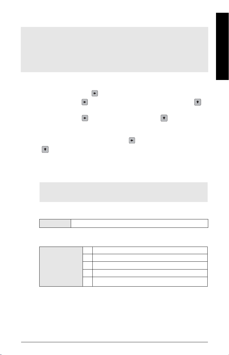
3. Editing in PROGRAM mode
Selecting a listed option:
• Navigate to the desired parameter.
• Press Right ARROW to open parameter
view.
• Press Right ARROW again to open Edit
•
• Scroll to a new selection. Press Right ARROW
• The LCD returns to parameter view and displays the new selection.
mode. The current selection is highlighted.
to accept it
7ML19985XN82 SITRANS LR250 (FF) – QUICK START MANUAL Page EN-17
4. Changing a numeric value:
0.200 M
+0.200
NEAR RANGE
2.5.1
0.200 M
NEAR RANGE
PREVIOUS
NEXT
EDITBACK
2.5.1
current
value
parameter
number
parameter name
• Navigate to the desired parameter.
• Press Right ARROW to open parameter
view. The current value is displayed.
English
• Press Right ARROW again to open Edit
mode. The current value is highlighted.
• Key in a new value.
• Press Right ARROW to accept it. The LCD
returns to parameter view and displays the new
selection.
Key Name Function
Up or
Down
ARROW
Right
ARROW
Left
ARROW:
Clear
Decimal
point
Plus or
minus sign
Numeral
to
Selecting
options
Numeric
editing
Selecting
options
Numeric
editing
Selecting
options
Numeric
editing
Numeric
editing
Numeric
editing
Numeric
editing
Numeric
editing
• Scrolls to item.
• Increments or decrements digits
• Toggles plus and minus sign
• Accepts data (writes the parameter)
• Changes from Edit to Navigation mode
• Moves cursor one space to the right
• or with cursor on Enter sign, accepts data and
switches from Edit to Navigation mode
•Cancels Edit mode without changing the parameter
• Moves cursor to plus/minus sign if this is the
first key pressed
• or moves cursor one space to the left
• or with cursor on Enter sign, cancels the entry.
• Erases the display.
• Enters a decimal point
• Captures the current path and displays corresponding value in LCD secondary region
• Changes the sign of the entered value.
• Enters the corresponding character.
Page EN-18 SITRANS LR250 (FF) – QUICK START MANUAL 7ML19985XN82
Quick Start Wizard via the handheld programmer
Notes:
• The Quick Start Wizard is a complete package and the settings are inter-related and
changes apply only after you select FINISH in Wizard Complete.
• Each time the Quick Start Wizard is initiated, the start-up settings are factory defaults. The
Wizard will not recall previous user-defined settings
• Default settings in the Quick Start Wizard are indicated with an asterisk (*) unless
explicitly stated.
1. Quick Start
a) Point the programmer at the display [from a maximum distance of 300 mm (1 ft)],
then press RIGHT arrow to activate PROGRAM mode and open menu level 1.
b) Press RIGHT arrow twice to navigate to menu item 1.1 and DOWN arrow to
enter the Quick Start Wizard.
c) Press RIGHT arrow to open Edit mode or DOWN arrow to accept default
values and move directly to the next item.
d) To change a setting, scroll to the desired item or key in a new value.
e) After modifying a value, press RIGHT arrow to accept it and press DOWN arrow
to move to the next item.
f) Quick Start settings take effect only after you select Finish in Wizard Complete.
1.1. Quick Start Wizard
Introduction
English
Note: The introduction screen is displayed only on the instrument when using the
handheld programmer. This screen is not part of the Quick Start Wizard when using
AMS Device Manager.
Introduction to Quick Start Wizard showing purpose of wizard: to setup common
applications easily.
Options
Language
CANCEL, NEXT
Selects the language to be used on the LCD and takes effect immediately.
* ENGLISH
DEUTSCH
Options
7ML19985XN82 SITRANS LR250 (FF) – QUICK START MANUAL Page EN-19
FRANÇAIS
ESPAÑOL
简体中文
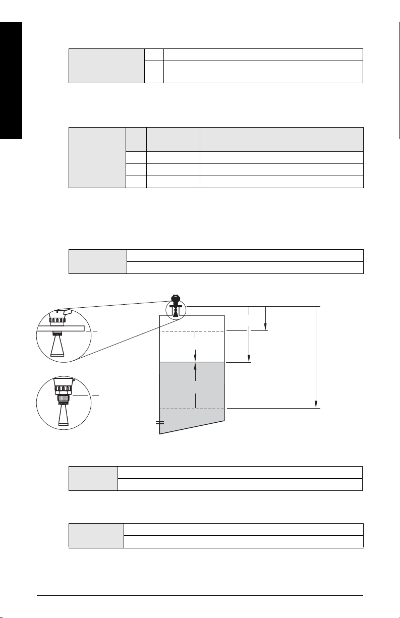
Material
High Cal.
Pt.
(process
full level)
Low Cal. Pt.
(process
empty
level)
level
space
distance
sensor
reference
point
sensor
reference
point
sensor
reference
point
flanged versions
threaded versions
Selects the appropriate echo processing algorithms for the material.
* LIQUID
Options
LIQUID LOW DK (low dielectric liquid – CLEF
enabled
)
algorithm
English
Response Rate
Sets the reaction speed of the instrument to measurement changes in the target
range.
Options
Response
Rate
* SLOW 0.1 m/min (0.32 ft/min)
MED 1.0 m/min (3.28 ft/min)
FAST 10.0 m/min (32.8 ft/min)
Fill Rate per Minute/Empty Rate per Minute
Use a setting just faster than the maximum filling or emptying rate (whichever is
greater).
Units
Sensor measurement units.
Options
M, CM, MM, FT, IN
Default: M
Low Calibration Point
Page EN-20 SITRANS LR250 (FF) – QUICK START MANUAL 7ML19985XN82
Distance from Sensor Reference to Low Calibration Point: usually process empty
level.
Values
High Calibration Point
Distance from Sensor Reference to High Calibration Point: usually process full level.
Values
Range: 0.0 0 to 20.00 m
Default: 20.00 m
Range: 0.00 to 20.00 m
Default: 0.00 m

Wizard Complete
Note: Wizard Complete is only displayed on the instrument when using the
handheld programmer. This step is not part of the Quick Start Wizard when using
AMS Device Manager.)
In order to save the Quick Start settings it is necessary to select FINISH to apply
changes.
Options
Press Mode to return to Measurement mode. The Level Transducer Block (LTB) will now
be operational. To view a measurement reading over the network, one of the Analog Input
Function Blocks (AIFB) will need to be setup and scheduled using a network configuration
software tool.
Note: If your application has a tank with obstructions, please see the full manual for details
on using Auto False Echo Suppression.
BACK, CANCEL, FINISH (Display returns to 1.1 Quick Start Wizard menu
when Quick Start is successfully completed.)
Communications via Foundation Fieldbus
Notes:
• The following instructions assume that the user is familiar with Foundation Fieldbus.
• You will need the full LR250 FF Operating Instructions manual to acquire the list of
applicable parameters.
AMS Device Manager
AMS Device Manager is a software package used to commission and maintain SITRANS
LR250 and other process instruments. Please consult the operating instructions or online help
for details on using AMS Device Manager. (You can find more information at
http://www.emersonprocess.com/AMS/.)
English
Electronic Device Description (EDD)
Note: SITRANS LR250 requires the EDD for AMS Device Manager version 9.0.
Check the product page of our website at: www.siemens.com/LR250, under Downloads, for the
latest version of EDD: SITRANS LR250 FF - Foundation Fieldbus - AMS V9.0.
1) Check that you have the latest version of the EDD for AMS Device Manager that matches
the firmware revision of your instrument, and if necessary download it from the product
page listed above. Save the files to your computer, and extract the zipped file to an easily
accessed location.
2) Launch AMS Device Manager – Add Device Type, browse to the unzipped EDD file and
select it.
3) The device is shipped with a unique tag, consisting of a manufacturer id and serial
number. The device tag can only be read from the device. It is not necessary to change
the device tag to make the device operational, however if you wish to change it, use AMS
Device Manager.
(continued on next page)
7ML19985XN82 SITRANS LR250 (FF) – QUICK START MANUAL Page EN-21

Set Device Tag via AMS Device Manager:
a) Launch AMS Device Manager – AMS Device Manager.
b) From the Device Connection View, right click on the FF Network icon and select
Rebuild Hierarchy.
c) Right click on the device icon, and choose Rename from the menu.
English
d) Enter a device tag and press Enter.
Startup
1) Launch AMS Device Manager – AMS Device Manager. (If AMS already running, go to
step 4.
2) From the Device Connection View, right click on the FF Network icon and select Rebuild
Hierarchy.
3) Double-click the device icon to open the startup screen. The startup screen shows device
identification details, and a navigation window on the left-hand side of the screen. (The
Block Status will show Out of Service at initial startup.)
4) Next, complete a master reset.
Master Reset
A master reset is recommended before first configuring a new device. (Block Status must be
Out of Service to perform a Master Reset.)
1) Navigate to Configure/Setup > Resource > Operation > Methods and click to open the
dialog window.
2) In the General field, click on Master Reset and click Next to perform reset to factory
defaults. Click Next to accept default reset to Factory Defaults.
3) Click FINISH then restart AMS to reload settings. Next, scan the device.
Scan Device
Scan Device uploads parameters from the device (synchronizes parameters) to AMS Device
Manager.
1) Open the pull-down menu Actions – Scan Device (upload parameters from the device to
AMS).
2) The next step when adding a new device is to configure and calibrate the device via the
Quick Start Wizard.
Sensor calibration
The LR250 FF does not need to be calibrated, only configured using the Quick Start Wizard
below.
Configuring a new device
Configure a new device using the Quick Start Wizard, found in the Resource Block of the
function group Configure/Setup.
Page EN-22 SITRANS LR250 (FF) – QUICK START MANUAL 7ML19985XN82
Quick Start Wizard via AMS Device Manager
Notes:
• Complete the steps in order. Click on Apply after revising parameters in each step, or
CANCEL to exit step without saving changes. (Note: Apply will write changes to the
device. OK will write changes to the device and exit to the Device Connection View.
CANCEL will exit to the Device Connection View without applying changes.)
• Do not use the Quick Start Wizard to modify individual parameters: see instead the AMS
chapter in the full LR250 FF Operating Instructions manual. (Perform customization only
after the Quick Start has been completed.)
• Values set using the Quick Start Wizard via AMS Device Manager are saved and recalled
each time it is initiated (unlike the Quick Start Wizard initiated via the handheld
programmer).
• To run the Quick Start Wizard for this device, the RESOURCE block must first be set to Out
of Service (OOS) mode, before any configuration changes (changes to parameters
affecting block output) can be written. (Setting RESOURCE block to OOS also sets LTB to
OOS.)
• After completing steps 1-4, review all settings in
further changes are required.
• After completing the Quick Start Wizard from AMS, you must manually place the
RESOURCE block in Automatic mode.
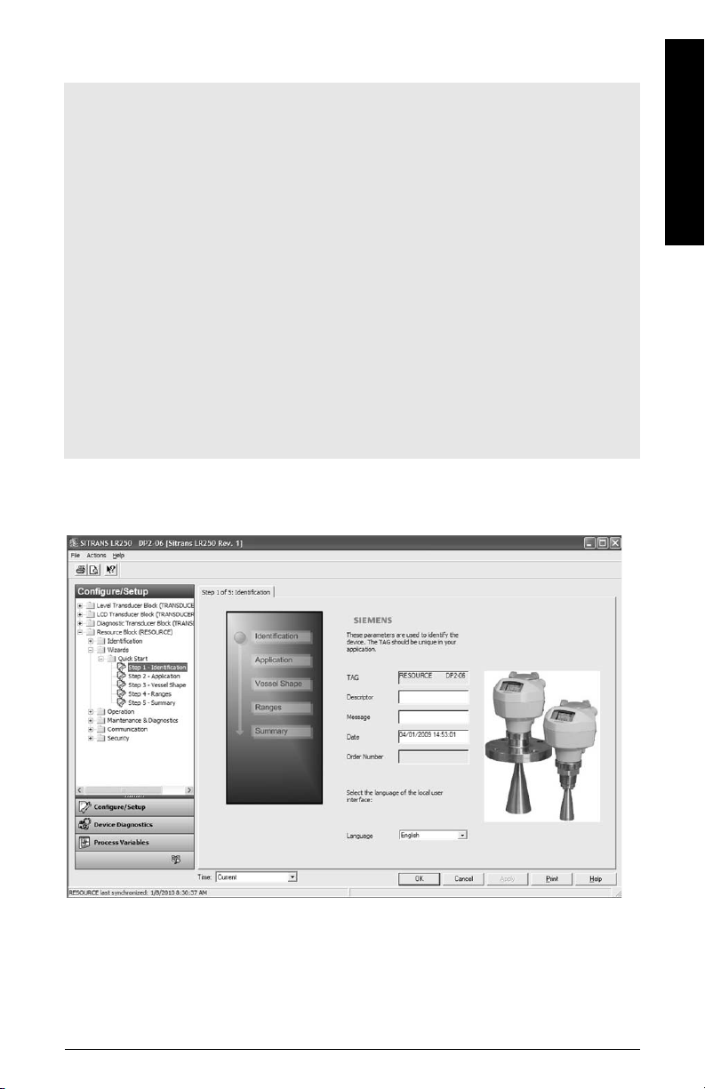
Launch AMS Device Manager and double-click the device icon from the Device Connection
View to open the startup screen. Navigate to Configure/Setup > Resource Block > Wizards >
Quick Start, and click on Step 1 - Identification.
Step 5 - Summary
. Return to steps1-4 if
English
Modify parameters as required, and click on Apply to save settings in each Step 1 to 4. Review
all parameter settings in Step 5 - Summary. Return to individual steps if further changes are
necessary. The Quick Start Wizard is now complete.
7ML19985XN82 SITRANS LR250 (FF) – QUICK START MANUAL Page EN-23
Maintenance
process
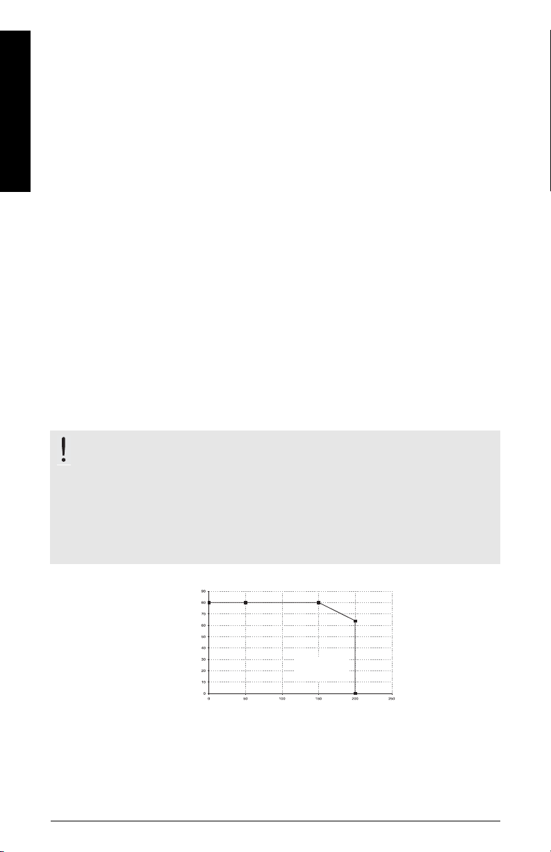
temperature
Ambient Temperature (
o
C)
Process
Temperature (
o
C)
Maximum Process
Temperatures versus
allowable ambient
SITRANS LR250 requires no maintenance or cleaning under normal operating conditions.
Under severe operating conditions, the antenna may require periodic cleaning. If cleaning
becomes necessary:
• Note the antenna material and the process medium, and select a cleaning solution that
English
will not react adversely with either.
• Remove the instrument from service and wipe the antenna clean using a cloth and
suitable cleaning solution.
Unit Repair and Excluded Liability
For detailed information, please see the inside back cover.
Antenna or electronics/enclosure replacement
• If the antenna requires replacement due to damage or failure, it may be replaced without
the need for re-calibration.
• Changing to a different antenna type may be performed by a Siemens authorized repair
center or personnel.
• If the electronics or enclosure require replacement due to damage or failure, please
ensure the correct antenna version is used, otherwise a re-calibration will need to be
performed by Siemens authorized personnel.
Maximum Process Temperature Chart
Flange Adapter versions of SITRANS LR250
WARNING: Internal temperature must not exceed +80 °C (+176 °F).
Notes:
• The chart is for guidance only and does not represent every possible process connection
arrangement. For example, it will NOT apply if you are mounting SITRANS LR250 directly
on a metallic vessel surface.
• It does not take into consideration heating from direct sunshine exposure.
• Use Minimum Value (3.3.1) and Maximum Value (3.3.2) to monitor the internal temperature.
Page EN-24 SITRANS LR250 (FF) – QUICK START MANUAL 7ML19985XN82
.

SITRANS LR250 (Foundation Fieldbus)
Kvikstart manual
Denne manual opridser de væsentligste karakteristika og funktioner af SITRANS LR250
(Foundation Fieldbus). Vi anbefaler kraftigt at anskaffe den detaljerede version af denne manual
for at kunne anvende apparatet fuldt ud. Den komplette manual kan downloades fra
produktsiden på vort website: www.siemens.com/LR250
lokale Siemens repræsentant.
Spørgsmål vedrørende indholdet af denne manual kan rettes til:
Siemens AG
Siemens Milltronics Process Instruments
1954 Technology Drive, P.O. Box 4225
Peterborough, Ontario, Canada, K9J 7B1
E-mail: techpubs.smpi@siemens.com
. Den trykte manual kan fås hos Deres
Copyright Siemens AG 2011.
Alle rettigheder forbeholdes
Vi opfordrer brugerne til at anskaffe de
autoriserede, indbundne manualer eller
læse de elektroniske versioner, der er
udarbejdet og skrevet af Siemens
Milltronics Process Instruments Inc.
Siemens Milltronics Process Instruments
Inc. påtager sig intet ansvar for indholdet
af delvise eller fuldstændige gengivelser
af indbundne eller elektroniske versioner.
MILLTRONICS® er et registreret varemærke, der tilhører Siemens Milltronics Process Instruments Inc.
Skønt vi har kontrolleret, at indholdet af denne
manual stemmer overens med de beskrevne
instrumenter, kan der stadig forekomme
variationer. Vi kan derfor ikke garantere en
fuldstændig overensstemmelse. Indholdet af
denne manual revideres jævnligt, og eventuelle
rettelser inkluderes i de efterfølgende udgaver. Vi
modtager gerne forslag til forbedringer.
Retten til ændringer af de tekniske data
forbeholdes.
Ansvarsfragåelse
Teknisk Support
Support er tilgængelig 24 timer i døgnet.
Adresse, telefon- og faxnummer på Siemens Automations lokale kontor kan findes på:
www.siemens.com/automation/partner:
• Klik på fanen Contact (Kontakt), vælg Service og klik derefter en gang til på
Service for at finde den relevante produktgruppe (+Automation Technology
(Automatiseringsteknik) > +Sensor Systems (Følersystemer) > +Process
Instrumentation (Procesinstrumentering) > +Level Measurement (Niveaumåling)
> +Continuous (Kontinuert)). Vælg Radar.
• Vælg land og derefter by/egn.
•Vælg Technical Support (Teknisk support) under Service.
For on-line teknisk support, gå til: www.siemens.com/automation/support-request
• Indtast apparatets navn (SITRANS LR250) eller ordrenummeret, klik på Search (Søg) og
vælg den relevante produkttype. Klik på Next.
• Indtast et nøgleord, der beskriver problemet. Gennemløb derefter den relevante
dokumentation eller klik på Next for at e-maile en beskrivelse af problemet til personalet i
Siemens Tekniske Support.
Siemens IA/DT Technical Support Center: telefon +49 (0)911 895 7222
Dansk
7ML19985XN82 SITRANS LR250 (FF) – KVIKSTART MANUAL Side DA-1

Sikkerhedsvejledning
De anførte advarsler skal overholdes for at sikre egen og andres sikkerhed samt for at
beskytte produktet og det tilknyttede udstyr. Disse advarsler ledsages af en tydeliggørelse af
graden af forsigtighed, der bør overholdes.
ADVARSEL: vedrører et advarselssymbol på produktet og betyder, at en
manglende overholdelse af de nødvendige forholdsregler kan føre til død,
alvorlig personskade og/eller omfattende materielle skader.
ADVARSEL
forholdsregler kan føre til død, alvorlig personskade og/eller omfattende
materielle skader.
1
: betyder, at en manglende overholdelse af de nødvendige
1
Bemærk: betyder vigtige oplysninger om produktet eller denne del af brugsvejledningen.
FCC-overensstemmelse
Kun for installationer i USA: Regler fra Federal Communications Commission (FCC)
ADVARSEL: Ændringer eller modifikationer, der ikke er udtrykkeligt godkendt af
Siemens Milltronics, kan ophæve brugerens ret til at benytte udstyret.
Bemærk:
• Dette udstyr er blevet testet og fundet at overholde grænserne for en klasse A digital
anordning i henhold til Afsnit 15 i FCC-reglerne. Disse grænser er beregnet til at yde en
rimelig beskyttelse mod skadelige interferenser, når anordningen anvendes i
kommercielle omgivelser.
• Dette udstyr frembringer, bruger og kan udstråle radiofrekvent energi, og kan, såfremt
det ikke installeres og bruges i overensstemmelse med instruktionsbogen, forårsage
Dansk
interferens, der kan virke forstyrrende for radiokommunikationen. Brugen af dette udstyr
i et beboelsesområde vil sandsynligvis forårsage skadelig interferens med radiokommunikationer, som brugeren i givet fald vil være nødsaget til at udbedre for egen regning.
SITRANS LR250
ADVARSEL: SITRANS LR250 bør kun anvendes som beskrevet i denne manual, da den
beskyttelse, apparatet yder, ellers kan forringes.
Bemærk: Dette produkt er beregnet til at anvendes i industriområder. Brugen at dette udstyr
i et beboelsesområde kan forårsage interferens med diverse frekvensbaserede
kommunikationsmidler.
SITRANS LR250 er en totråds 25 GHz pulsradarniveautransmitter til kontinuert overvågning af
væsker og opslæmninger i lagertanke, inklusive ved højt tryk og høj temperatur, i en afstand af
op til 20 m (66 ft). Den er ideelt egnet til små tanke og medier med lav dielektricitetskonstant.
Dette apparat består af et elektronisk kredsløb, der er koblet til en hornantenne og en
procestilslutning af enten gevind- eller flangetypen. Der fås også en PVDF-antenne med gevind.
SITRANS LR250 understøtter kommunikationsprotokollen Foundation Fieldbus (FF) .
Signalbehandlingen anvender Process Intelligence, der har vist sit værd i felten i over
1.000.000 applikationer verden over (ultralyd og radar). Dette instrument kan opsættes som en
FF (H1) Link Master.
1.
Dette symbol anvendes, når der ikke er noget tilsvarende advarselssymbol på produktet.
Side DA-2 SITRANS LR250 (FF) – KVIKSTART MANUAL 7ML19985XN82
Tekniske data
omgivelsestemperatur
(omkring instrumenthuset)
–40 °C til 80 °C (–40 °F til +176 °F)
apparatets
navneplade
procestilslutningsskilt
procestemperaturen ved procestilslutningen:
standard hornantenne:
- med FKM O-ring: –40
o
C til +200 oC (-40 oF til +392 oF)
- med FFKM O-ring: –20
o
C til +200 oC (-4 oF til +392 oF)
PVDF-antenne med 2" NPT / BSPT / G-gevind:
−40 til +80 °C (−40 til +176 °F)
For en fuldstændig liste, se SITRANS LR250 (FF) Betjeningsvejledning. For oplysninger om
godkendelser henvises der til procesmærkeskiltet.
Omgivende temperatur/Driftstemperatur
Bemærk:
• Den maksimale temperatur afhænger af procestilslutningen, antennematerialerne og
trykket i beholderen: se
For yderligere oplysninger, se kurver over procestryk- og temperaturreduktionen i den
komplette manual.
• De tilladelige procestemperaturer og –tryk afhænger af oplysningerne på procestilslutningsskiltet. Referencetegningen, der er angivet på skiltet, kan fås på produktsiden på
vort website på www.siemens.com/LR250
diagrammer) > Level Measurement (Niveaumåling) > Continuous - Radar (Kontinuert Radar). Yderligere oplysninger om procestilslutninger kan fås på siden Installation Drawings (Installationsdiagrammer) under Process Connection Diagrams (Procestilslutningsdiagrammer).
• Signalamplituden stiger med horndiameteren, så brug den største anvendelige størrelse.
• Eventuelle forlængelser (ekstraudstyr) kan installeres under gevindet.
•Se
Diagram over maksimale procestemperaturer
Elektriske opsætninger ved installationer i risikoområder
, Support > Installation Drawings (Installations-
på side 24 for yderligere detaljer.
på side 9.
Dansk
Strømforsyning
Almen brug:
Grundlæggende sikker:
Ikke-gnistdannende/Energibegrænset:
Ikke-antændingsfarlig:
• Strømforsynes gennem bussen 9-32 V DC, ifølge IEC 61158-2 (Foundation Fieldbus)
• Strømforbrug 20 mA
Godkendelser
Bemærk:
• Apparatets navneplade angiver de godkendelser, der gælder for netop Deres apparat.
• Brug passende kabelrørstætninger for at bevare IP- eller NEMA-klassificeringen.
• Almen brug CSA
• Radio FCC, Industry Canada, Europa ETSI EN 302-372
7ML19985XN82 SITRANS LR250 (FF) – KVIKSTART MANUAL Side DA-3
USA/C
, CE, FM, NE 21, C-TICK, KC
9-32 V DC

Godkendelser (fortsat)
• Risikoområder
Egensikker
(International) IECEx SIR 09.0148X, Ex ia IIC T4 Ga
Ex tD A20 IP67 T90 °C Da
(USA/Canada) FM/CSA
Klasse I, Div. 1, Gruppe A, B, C, D
Klasse II, Div. 1, Gruppe E, F, G
Klasse III T4
(Brasilien) INMETRO TUV 11.0309 X, Ex ia IIC T4 Ga
Ex ia IIIC T90 ºC Da IP65/IP67
TUV #: OCP 0004
Ikke-gnistdannende/Energibegrænset
Ikke-antændingsfarlig
• Maritimt Lloyd’s Skibsregister
1
(Europa) ATEX II 1G, Ex ia IIC T4 Ga
ATEX II 1D, Ex tD A20 IP67 T90 °C Da
(Kina) NEPSI Ex ia IIC T4/ DIP A20 T
2
(Europa) ATEX II 3G Ex nA/nL IIC T4 Gc
(Kina) NEPSI Ex nA II T4/ Ex nL IIC T4
3
(USA/Canada) FM/CSA Klasse I, Div. 2, Gruppe A, B, C, D T5
ABS Typegodkendelse
Bureau Veritas
T90 °C IP6X
A,
Dansk
Anvendelser under tryk
4
ADVARSLER:
• Forsøg aldrig at løsne, afmontere eller adskille procestilslutningen eller
instrumenthuset, mens indholdet er under tryk.
• Brugeren er ansvarlig for at vælge sammenboltnings- og pakningsmaterialer, der ligger inden for flangens begrænsninger og dens påtænkte anvendelse, og som passer til anvendelsesforholdene.
• Ukorrekt installation kan medføre tab af procestryk.
Bemærk:
• Procestilslutningsskiltet skal forblive sammen med grænsefladen til procestrykket
Såfremt instrumentpakken udskiftes, skal procestilslutningsskiltet overføres til den nye
enhed.
• SITRANS LR250 enhederne er testet hydrostatisk og opfylder eller overskrider kravene i
ASME Boiler and Pressure Vessel Code samt det europæiske Trykudstyrsdirektiv.
1.
Se
Egensikker elinstallation
2.
Se
Ikke-gnistdannende/Energibegrænset elinstallation
3.
Se
Ikke-antændingsfarlig elinstallation (kun for USA/Canada)
4.
Grænsefladen til procestrykket omfatter de komponenter, der fungerer som en barriere mod tryktab
fra procestanken: det vil sige kombinationen af procestilslutningsdelen og emitteren, men normalt
eksklusive den elektriske indkapsling.
Side DA-4 SITRANS LR250 (FF) – KVIKSTART MANUAL 7ML19985XN82
på side 11.
på side 12.
på side 13.
4)
.
Trykudstyrsdirektivet, 97/23/EF
min. afstand:
10 mm (0,4")
PVDF-antenne med gevind Hornantenne af rustfrit stål
Min. diam. 50 mm (2")
min. afstand:
10 mm (0,4")
Siemens niveautransmittere med procesmontering af typen flange, gevind eller sanitær
klemme omfatter ikke eget trykbærende hus og er derfor ikke underlagt Trykudstyrsdirektivet
som tryk- og sikkerhedshjælpemidler (jf. EU-Kommissionens vejledning 1/8 og 1/20).
Installation
ADVARSLER:
• Installationen må kun udføres af kvalificeret personale og i overensstemmelse med de lokale bestemmelser.
• Håndtér altid apparatet ved at tage fat i instrumenthuset, aldrig procestilslutningsskiltet, for at undgå beskadigelse.
• Pas særligt på ved håndtering af PVDF-antennen med gevind. Enhver beskadigelse af antennens overflade, navnlig på spidsen, kan påvirke ydelserne.
• Konstruktionsmaterialerne er valgt på basis af deres kemiske kompatibilitet
(eller inerti) ved almindelig brug. Hvis de skal udsættes for særlige omgivelser, bør foreneligheden kontrolleres i tabeller over kemiske kompatibiliteter
inden installationen.
Bemærk:
• I den Europæiske Union og medlemslandene heraf skal installationen foretages i henhold
til ETSI EN 302372.
• For oplysninger om godkendelser henvises der til apparatets navneskilt.
• Det serienummer, der er præget i hver procestilslutningsdel, udgør et unikt
identifikationsnummer med angivelse af fabrikationsdatoen.
Eksempel: MMDDYY – XXX (hvor MM = måned, DD = dag, YY = år og XXX= fortløbende
nummer på den fremstillede enhed)
• Yderligere er angivet (hvis pladsen tillader det) flangekonfiguration, størrelse, trykkategori,
materiale og materialets varmekode.
Dansk
Mundstykkets udformning
• Antennens ende skal rage mindst 10 mm (0,4”) frem for at undgå, at falske ekkoer
tilbagekastes fra mundstykket.
• For PVDF-antennen med gevind er den mindste anbefalede diameter af mundstykket
51 mm (2").
• Der fås en antenneforlængelse (100 mm/ 3,93") for alle versioner på nær PVDF-antennen
med gevind.
7ML19985XN82 SITRANS LR250 (FF) – KVIKSTART MANUAL Side DA-5
 Loading...