

Siemens SITRANS LPS200 Operating Instructions Manual
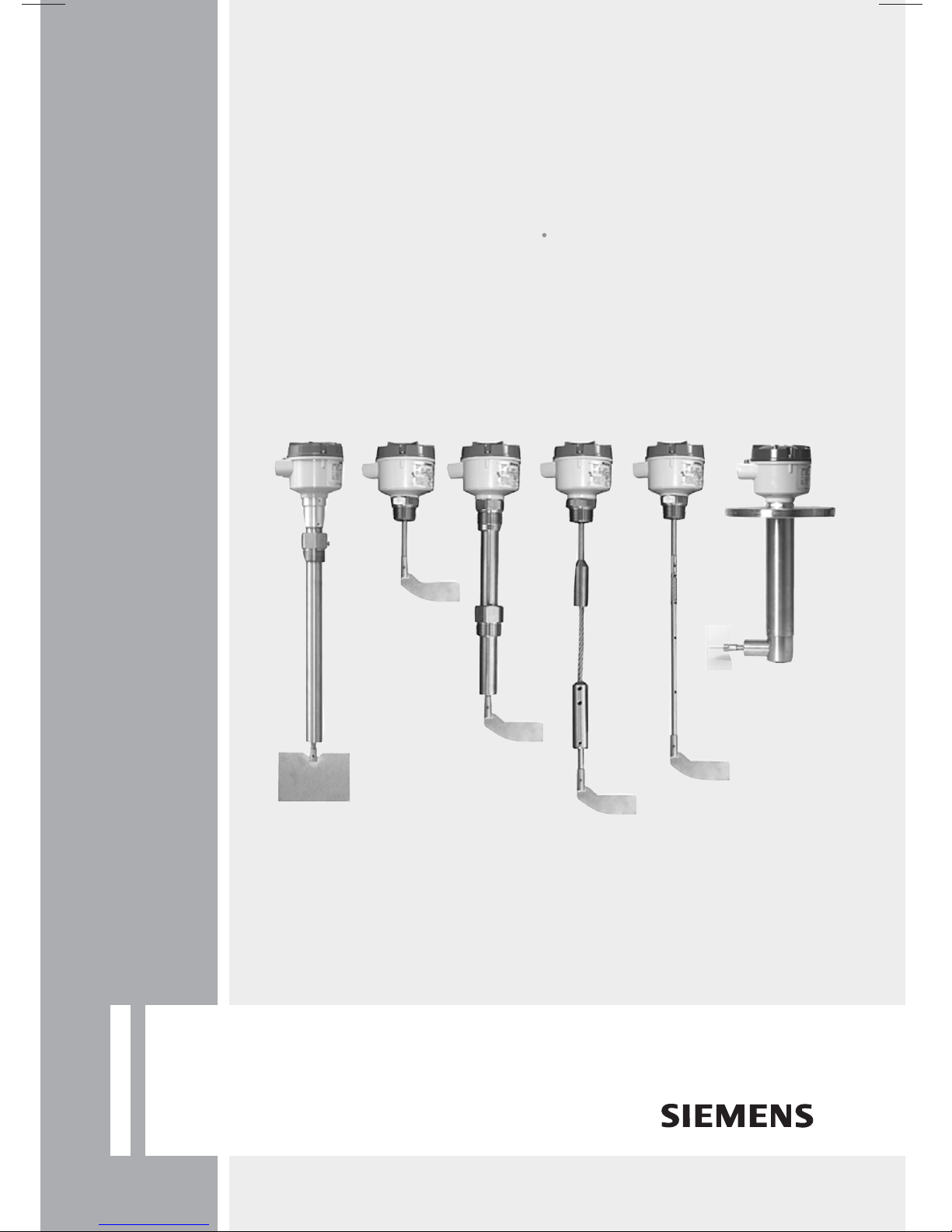
Rotating Paddle Switch
SITRANS LPS200
Operating Instructions 08/2012
SITRANS

Safety Notes
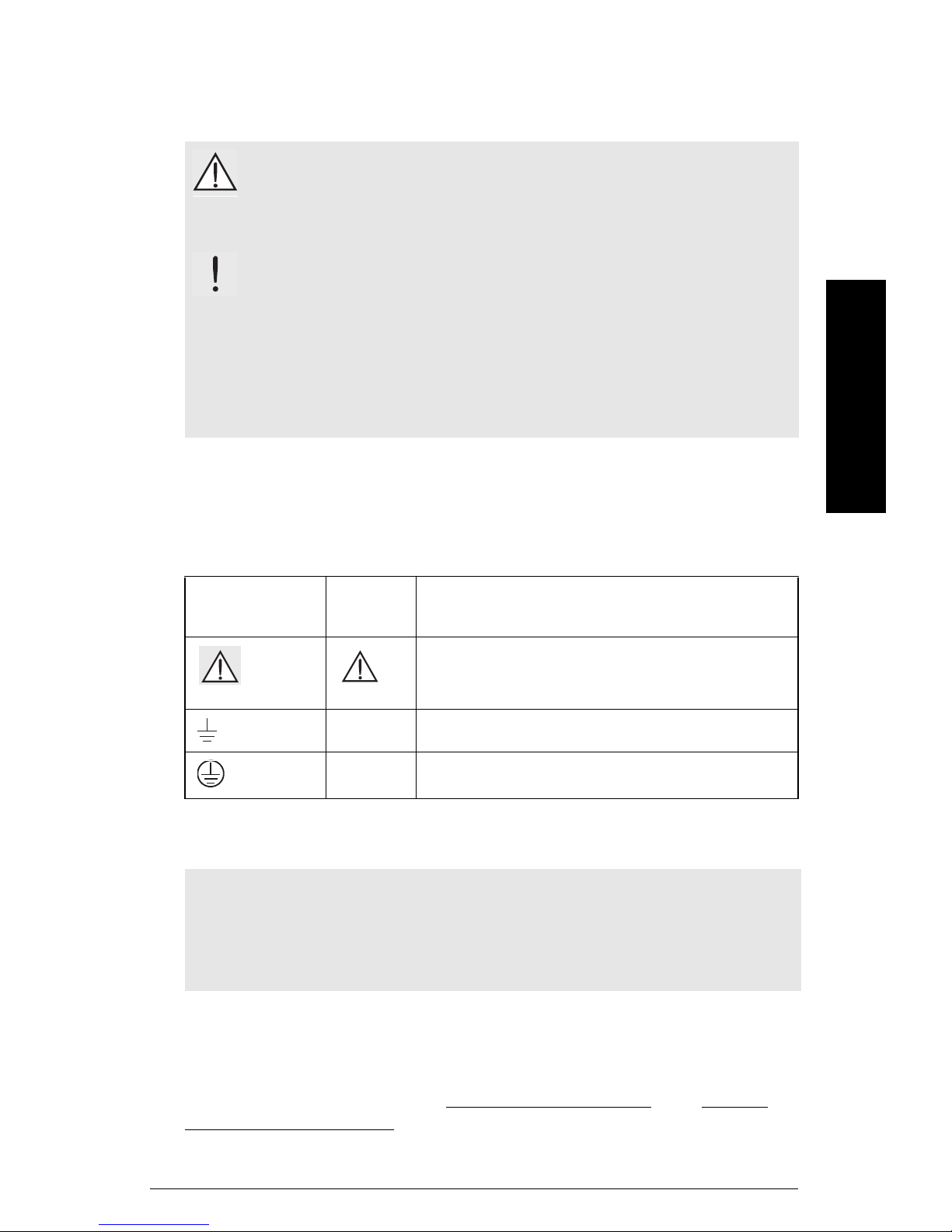
Special attention must be paid to warnings and notes highlighted from the rest of the text
by grey boxes.
WARNING: relates to a caution symbol on the product, and means
that failure to observe the necessary precautions can result in
death, serious injury, and/or considerable material damage.
English
mmmmm
WARNING
1
: means that failure to observe the necessary
precautions can result in death, serious injury, and/or considerable
material damage.
CAUTION: means that failure to observe the necessary precautions can
result in considerable material damage.
Note:
manual.
1.
means important information about the product or that part of the operating
This symbol is used when there is no corresponding caution symbol on the
product.
Safety marking symbols
In
manual
On
Product
Description
(Label on product: yellow background.)
Caution: refer to accompanying documents (manual) for details.
Earth (ground) Terminal
Protective Conductor Terminal
The Manual
Notes:
• Please follow the installation and operating procedures for a quick, trouble-free
installation and to ensure the maximum accuracy and reliability of your SITRANS LPS200.
• This manual applies to SITRANS LPS200 only.
This manual will help you set up your SITRANS LPS200 for optimum performance. We
always welcome suggestions and comments about manual content, design, and
accessibility.
Please direct your comments to techpubs.smpi@siemens.com
Siemens Milltronics manuals, go to www.siemens.com/processautomation
. For the complete library of
.
7ML19985FS62 SITRANS LPS200 – OPERATING INSTRUCTIONS Page EN-1

mmmmm
SITRANS LPS200 Introduction
Notes
• Installation, maintenance, and commissioning must be performed by qualified
English
SITRANS LPS200 Features
technical personnel.
• SITRANS LPS200 must be used only in the manner outlined in this instruction
manual.
• This product is intended for use in industrial areas. Operation of this equipment in a
residential area may cause interference to several frequency based
communications.
The SITRANS LPS200 rotating paddle switch is used for level monitoring of bulk
materials. It can be used to detect full, demand, or empty conditions in silos, hoppers, or
storage vessels of materials such as grain, feed, cement, plastic granulate, and wood
chips. The paddle switch measures bulk densities as low as 100 g/l (6.2 lb/ft
standard measuring vane, 35 g/l (2.2 lb/ft3) with the optional hinged vane, or 15 g/l
(0.9 lb/ft3) with the optional rectangular vane.
• High integrity mechanical seal
• AC, DC, or switch-selectable power supply
• Unique friction clutch mechanism. When the measuring vane encounters sudden
resistance, the friction clutch slips to prevent internal component damage.
• Optional fail-safe function alarms on fault conditions or component failure
• Rotatable enclosure
• Optional vanes for use with high and low bulk densities to 15 g/l (0.9 lb/ft
• Compact, rigid extension (top mounted only), angled rigid extension, and cable
extension configurations available
• High temperature and high pressure models available
• Optional extension kit available for the compact version
3
) with the
3
)
SITRANS LPS200 Applications
• Grain, feed, cement, plastic granulate, wood chips, rice, soybeans, etc.
• Low or high bulk density materials
Principle of Operation
A low revolution gearing motor drives a rotating measuring vane. When material reaches
the rotating vane, rotation stops, actuating a microswitch contact closure. When the
vane is no longer covered, rotation resumes and the microswitch reverts to its normal
condition.
The synchronous induction motor is freely suspended within the housing. When the
rotation is slowed by the material, the reaction torque is used to operate a micro-switch
that gives an electrical signal to stop the motor. When the material level moves away
from the rotating vane, a spring draws the motor back into operating position, the
microswitch returns to operating position, and the motor is switched back on.
Two motor speeds are available: 1 rpm, for storage silos
Page EN-2 SITRANS LPS200 – OPERATING INSTRUCTIONS 7ML19985FS62
5 rpm, for faster process requirements

Specifications
Note: Siemens Milltronics makes every attempt to ensure the accuracy of these
specifications but reserves the right to change them at any time.
Power
• 115 V AC, 50 to 60 Hz, 4 VA
• 230 V AC, 50 Hz, 6 VA
• 24 or 48 V AC
• 24 V DC, 2.5 W
All voltages ± 15 % (including ± 10 % according to IEC 61010-1)
Performance
Alarm delay
• 1 rpm model (storage applications) approx. 1.3 s
• 5 rpm model (process applications) approx. 0.26 s
Sensitivity
• adjustable spring tension position
• optional measuring vanes available, depending on customer sensitivity
requirements
English
mmmmm
Approximate minimum material density
Standard measuring vane
• 100 g/l (6.2 lb/ft
• 200 g/l (12.5 lb/ft
Hinged measuring vane
• 35 g/l (2.2 lb/ft
• 70 g/l (4.4 lb/ft
Rectangular measuring vane (98 x 250 mm)
• 15 g/l (0.9 lb/ft
• 20 g/l (1.2 lb/ft
• See “Measuring Vanes” on page 10 for more information.
3
) when vane is covered by 10 cm (4") of material
3
) when vane is covered by more than 10 cm (4") of material
3
) when vane is covered by 10 cm (4") of material
3
) when vane is covered by more than 10 cm (4") of material
3
) when vane is covered by 10 cm (4") of material
3
) when vane is covered by more than 10 cm (4") of material
Alarm Output
• microswitch SPDT or DPDT contact 5 A at 250 VAC, non-inductive
microswitch SPDT or DPDT contact 4 A at 30 V DC, non-inductive
7ML19985FS62 SITRANS LPS200 – OPERATING INSTRUCTIONS Page EN-3

mmmmm
Mechanical
English
Process Connections
• threaded connection 1", 1¼”, 1½" NPT or 1", 1¼”, 1½" BSP
• material: stainless steel 303 (1.4305) or 316L
(1.4404), optional aluminum
• flanged connection DN 32 PN 6, DN 100 PN 6, DN 100 PN 16,
2", 3", 4" ASME, 150 lb, B 16.5 (1.4541/321)
• Tri-clamp 2" DN50 ISO 2852
Enclosure
• construction epoxy coated aluminum
• conduit entry 2 x M20 x 1.5, or
2 x ½” NPT
• ingress protection Type 4X/NEMA 4X/IP66
• vane and shaft construction stainless steel 304 and 303 (1.4301 and 1.4305)
or 316L (1.4404)
Weight
Standard temperature:
• compact 1.8 kg (4.0 lb)
• extended 2.2 kg (4.9 lb)
• angled extended 4.0 kg (8.8 lb)
• cable 3.2 kg (7.1 lb)
High temperature:
• compact 2.6 kg (5.7 lb)
• extended 3.0 kg (6.6 lb)
• angled extended 5.2 kg (11.4 lb)
• cable 4.0 kg (8.8 lb)
Environmental
• location indoor/outdoor
• altitude max. 2000 m (6562 ft)
• ambient temperature –25 to +60 °C (–13 to +140 °F)
• relative humidity 0 to 100 %, suitable for outdoor (ingress
• Installation category III
• Pollution degree 2
protection: Type 4X/NEMA 4X/IP66)
Note: With the heated enclosure option, the ambient temperature rating improves to
–40 to +60 °C (–40 to +140 °F).
Page EN-4 SITRANS LPS200 – OPERATING INSTRUCTIONS 7ML19985FS62

Process
Temperature
Standard model:
• –25 to +80 °C (–13 to +176 °F)
• CSA temperature code: T5
• maximum surface temperature +120 ºC (+248 ºF) [ATEX relevant]
High temperature option:
• CE and General Purpose –25 to +600 °C (–13 to +1112 °F)
• FM/ATEX Hazardous –25 to +250 °C (–13 to +482 °F)
• CSA Class II Group E, F –25 to +195 °C (–13 to +383 °F), CSA
temperature code: T2D
• CSA Class II Group G –25 to +160 °C (–13 to +320 °F), CSA
temperature code: T3B
• maximum surface temperature +220 ºC (+428 ºF) [ATEX relevant]
Pressure
• standard model max. 0.8 bar, gauge (11.6 psi, gauge)
• high pressure options max. 5 bar, gauge (72.5 psi, gauge)
max. 10 bar, gauge (145 psi, gauge)
Note: The device construction allows over-pressure between –0.2 and 0.1 bar in
hazardous areas.
English
mmmmm
WARNINGS:
• This product is designated as a Pressure Accessory per Directive
97 / 23 / EC, and is not
intended for use as a safety device.
• Materials of construction are chosen based on their chemical
compatibility (or inertness) for general purposes. For exposure to
specific environments, check with chemical compatibility charts
before installing.
Approvals
• FM/CSA Class II, Div. 1, Group E, F, G, Class III
• ATEX II 1/2 D (dust explosion)
• IECEx t IIIC Da/Db
•CE
•C-TICK
•FM/
CSA
C
(see product nameplate for approval details)
General Purpose
USA
7ML19985FS62 SITRANS LPS200 – OPERATING INSTRUCTIONS Page EN-5

mmmmm
Installation
Mounting
English
Notes:
• Installation shall be performed by qualified personnel and in accordance with local
governing regulations.
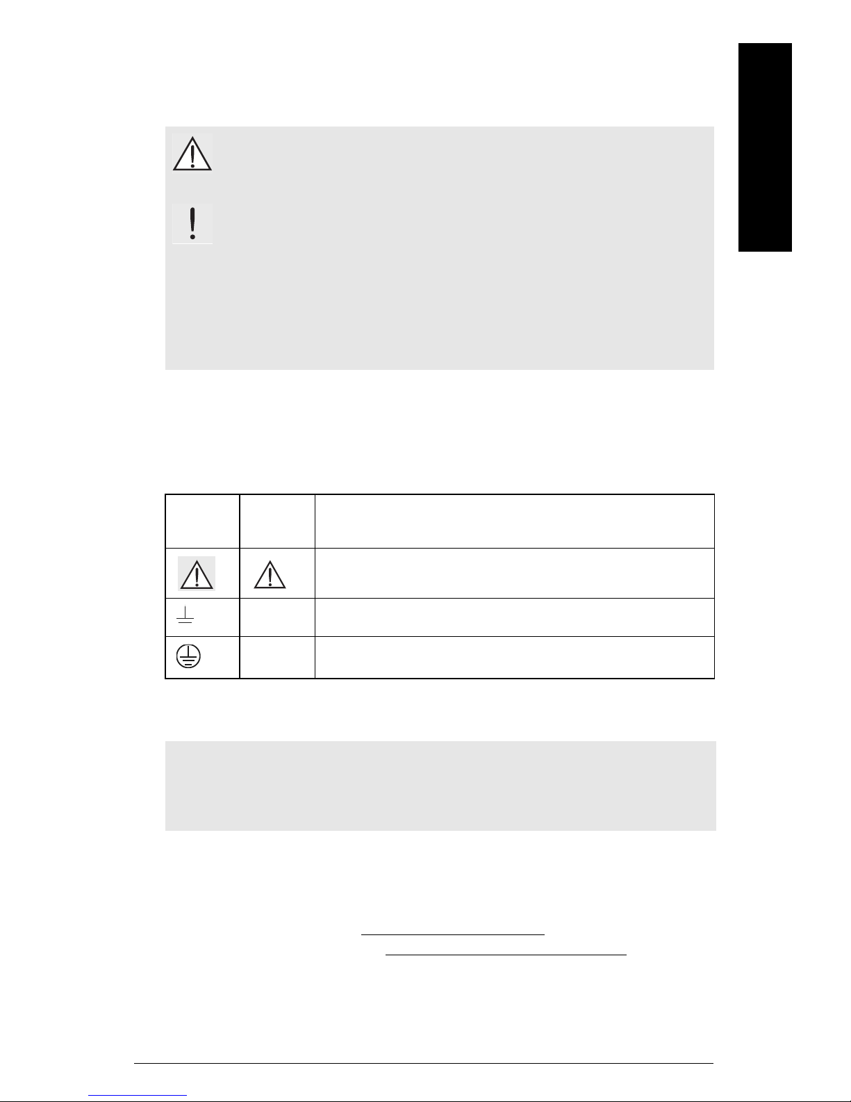
• For heavy material, only top mounting of paddle switch is recommended.
• Compact SITRANS LPS200 is recommended for side mounting on bins for low or
intermediate levels.
• For SITRANS LPS200 Cable extension, the maximum pull force of the rope must not
exceed 4 kN (28 kN with reinforced option).
• When installing LPS200 with rigid extension kit, ensure product is top mounted and
never side or angle mounted.
WARNINGS:
• This product is designated as a Pressure Accessory per
Directive 97/23/EC, and is not
• Improper installation may result in loss of process pressure.
intended for use as a safety device.
SITRANS LPS200 is normally mounted into the vessel top (full detector) or through the
tank wall at the detection level (full, demand or empty detector). SITRANS LPS200 can be
installed through a standard 1¼" NPT or 1½" BSPT pipe coupling, depending on the
chosen process thread.
Page EN-6 SITRANS LPS200 – OPERATING INSTRUCTIONS 7ML19985FS62
English
After mounting and as a precaution
against water ingress into the
housing, turn the housing clockwise
until the cable entries point
downward.
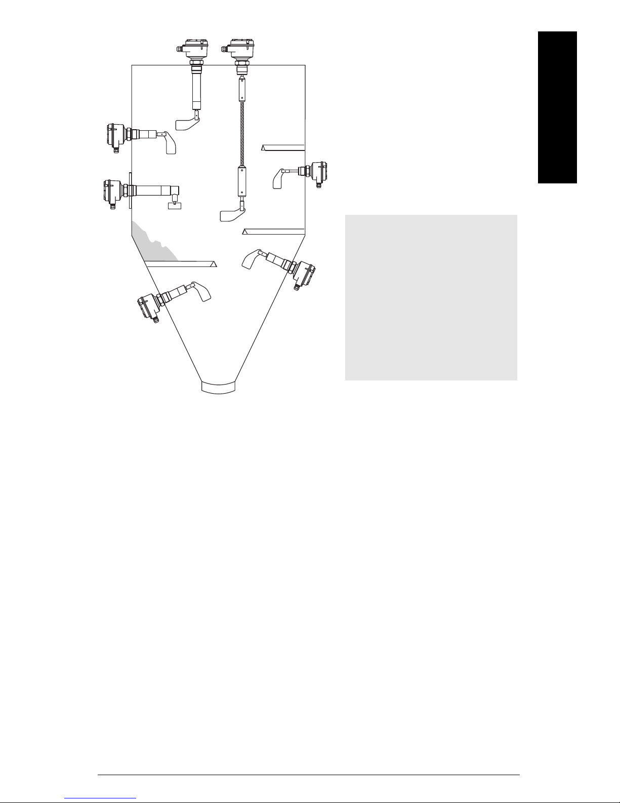
Notes:
• Ensure measuring vane is out of
any region that is susceptible to
build-up.
• For heavy material loads and
protection against falling
material, provide angled
protection.
• Ensure cable gland faces
downward to avoid water
intrusion.
mmmmm
7ML19985FS62 SITRANS LPS200 – OPERATING INSTRUCTIONS Page EN-7
mmmmm
Caution: Keep SITRANS LPS200
out of path of falling material.
Caution: Protect shaft and
measuring vane from falling
material.
sensitivity
spring
low
medium
high
AC (SPDT relay) version shown
Process Cautions
English
Sensitivity
To adjust the sensitivity of SITRANS LPS200, use pliers to move the sensitivity spring to
the appropriate position (factory setting is medium). The optional measuring vanes can
also improve sensitivity.
Page EN-8 SITRANS LPS200 – OPERATING INSTRUCTIONS 7ML19985FS62
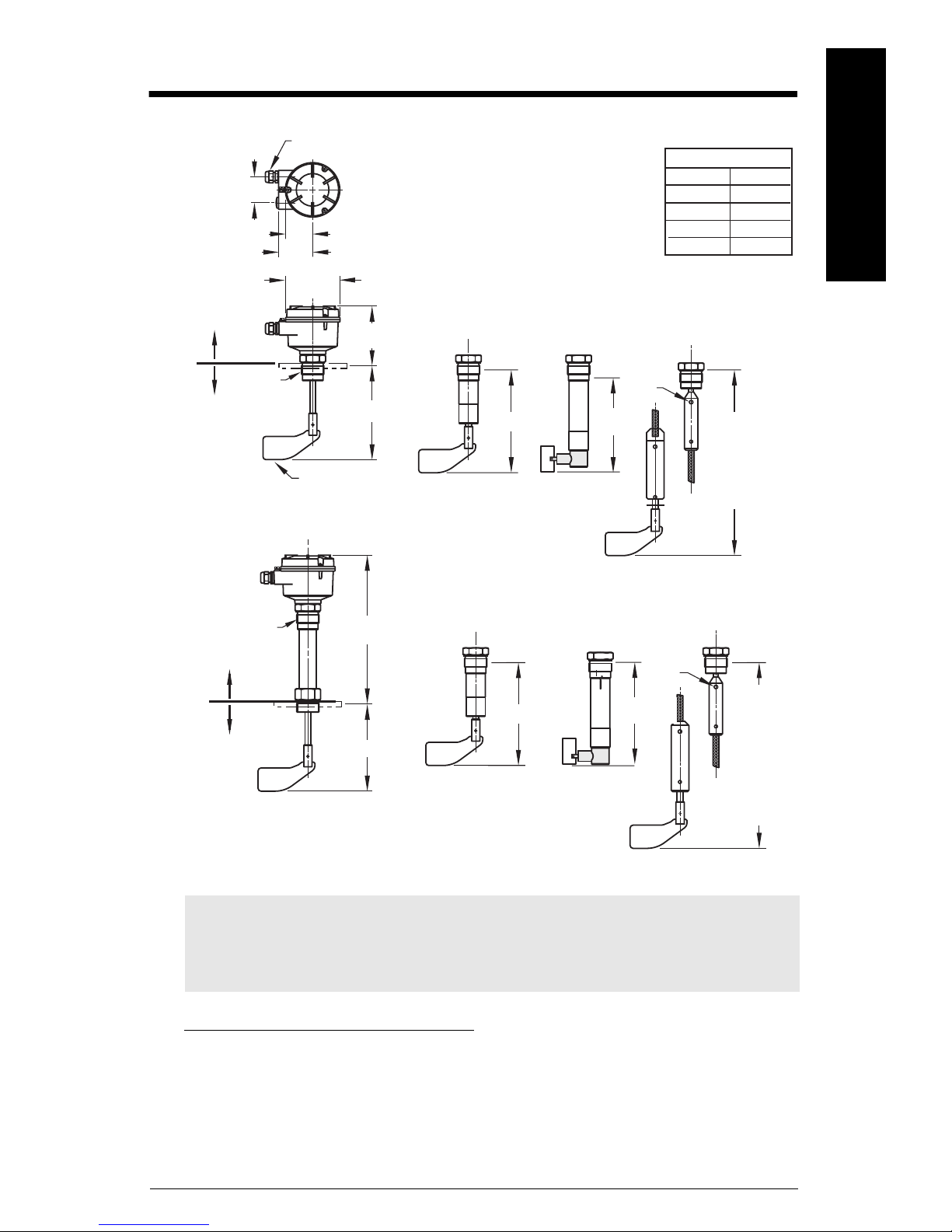
Dimensions and Temperature Ranges
L = Length
150 mm
5.91"
200 mm
250 mm
300 mm
7.87"
9.84"
11.81"
100 mm
3.94"
60 mm (2.36")
75 mm (2.95")
60 mm (2.36")
BSP: 20.5 mm (0.81")
NPT: 24 mm (0.94")
measuring vane
rope
fixing
conduit connection M20 or ½” NPT
123 mm (4.84")
120 mm
(4.72")
A
2)
rope
fixing
Zone 21 (ATEX
Category 2D
IECEx EPL Db)
Zone 20 (ATEX
Category 1D
IECEx EPL Db)
High Temperature Model: compact version
2000 mm
(78.74")
standard,
can be
shortened
by the
customer,
total length
available
10000 mm
(393.7")
2000 mm
(78.74")
standard: can
be shortened
by the
customer
process
temperature
–25 to +80 oC
(–13 to +176 oF)
ambient
temperature:
–25 to +60 oC
(–13 to +140 oF)
process
temperature
3)
–25 to +250 °C
(–13 to +482 °F)
extended angle extension rope option
ambient
temperature:
–25 to +60 oC
(–13 to +140 oF)
125 to 300 mm
(4.92 to 8.46")
125 to 300 mm
(4.92 to 8.46")
thread length:
L
1)
L
1)
L
1)
L
1)
optional
process
range
thread length:
BSP: 20.5 mm (0.81")
NPT: 24 mm (0.94")
extended angle extension rope option
Zone 21 (ATEX
Category 2D
IECEx EPL Db)
Zone 20 (ATEX
Category 1D
IECEx EPL Db)
Standard Model: compact version
1) 2) 3)
English
mmmmm
Notes:
• For heavy material, only top mounting of paddle switch is recommended.
• Compact LPS200 is recommended for side mounting on bins for low or intermediate
material levels.
1)
For 35 x 106 mm boot-shaped, and 65 x 210 mm hinged measuring vanes, add 16 mm (0.63")
to extension length.
2)
A = 200 mm (7.87") for 250 ºC (482 ºF);
= 400 mm (15.74") for 600 ºC (1112 ºF);
3)
For use with all approval options except CSA Class II. See “Temperature” on page 5 for
more details.
7ML19985FS62 SITRANS LPS200 – OPERATING INSTRUCTIONS Page EN-9
mmmmm
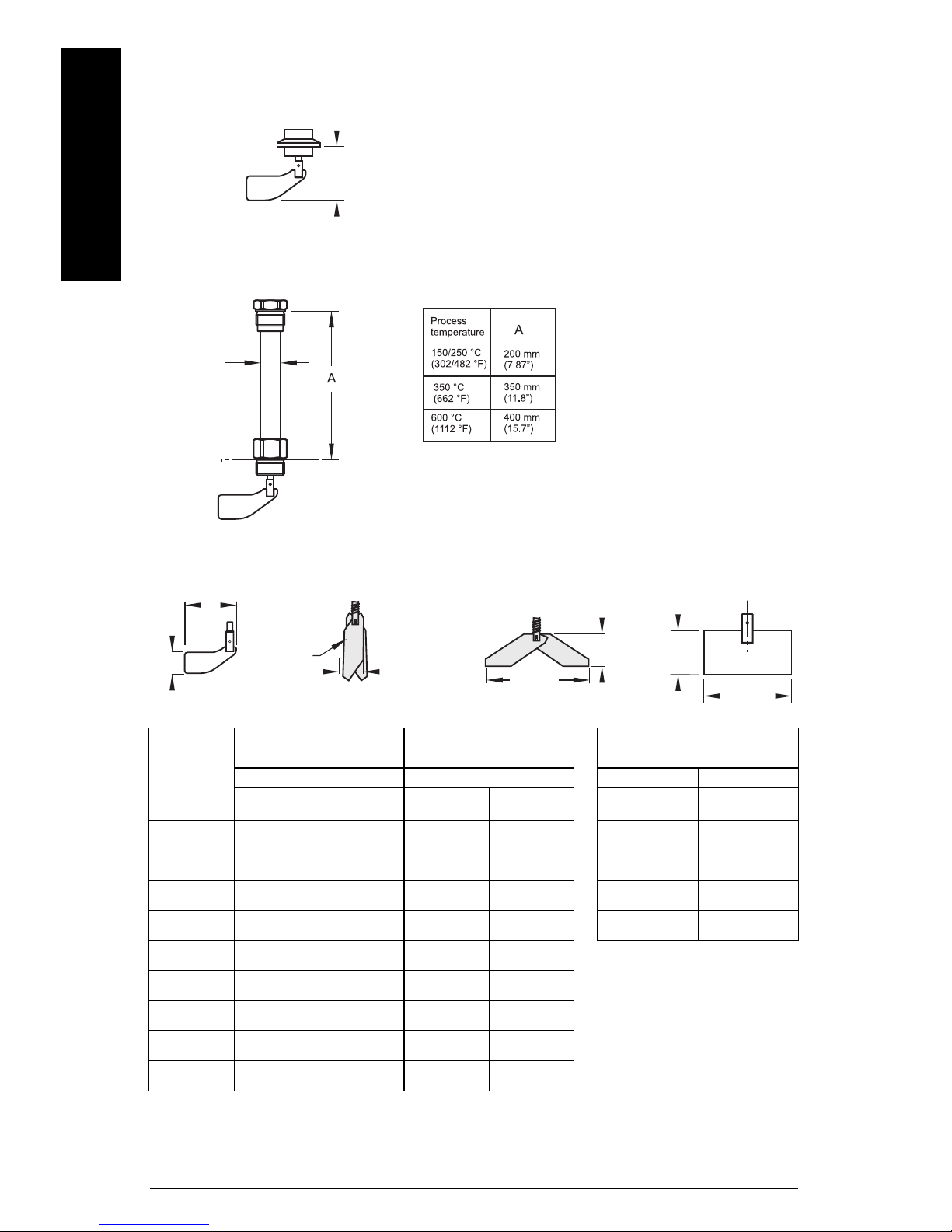
Standard Model: Triclamp
70 to 1500 mm
(2.76 to 59")
High Temperature Model: Temperature Extended Shaft
ø33 mm
(ø1.3")
fold together
to lead into
mounting hole
min. 37 mm
(1.46")
210 mm
(8.27")
65 mm
(2.56")
35 mm
(1.38")
106 mm
(4.17")
Hinged
Rectangular
A
B
Standard
Extensions
English
Measuring Vanes
Vane completely covered
with bulk material
Van e
boot shaped
35 x 106 mm
boot shaped
28 x 98 mm
rectangular
50 x 98 mm
rectangular
50 x 150 mm
rectangular
50 x 250 mm
rectangular
98 x 150 mm
rectangular
98 x 250 mm
hinged
65x 210 mm
hinged
60 x 200 mm
Spring Adjustment Spring Adjustment A B
Light Central
(factory setting)
200 g/l
(12.5 lb/ft³)
300 g/l
(18.7 lb/ft³)
300 g/l
(18.7 lb/ft³)
80 g/l
(5.0 lb/ft³)
30 g/l
(1.9 lb/ft³)
30 g/l
(1.9 lb/ft³)
20 g/l
(1.2 lb/ft³)
70 g/l
(4.4 lb/ft³)
70 g/l
(4.4 lb/ft³)
300 g/l
(18.7 lb/ft³)
500 g/l
(31.2 lb/ft³)
500 g/l
(31.2 lb/ft³)
120 g/l
(7.5 lb/ft³)
50 g/l
(3.1 lb/ft³)
50 g/l
(3.1 lb/ft³)
30 g/l
(1.9 lb/ft³)
100 g/l
(6.2 lb/ft³)
100 g/l
(6.2 lb/ft³)
Bulk material covers the
vane up to 10 cm (3.93")
(6.2 lb/ft³)
(9.4 lb/ft³)
(9.4 lb/ft³)
(2.5 lb/ft³)
(0.9 lb/ft³)
(0.9 lb/ft³)
(0.9 lb/ft³)
(2.2 lb/ft³)
(2.2 lb/ft³)
Light Central
(factory setting)
100 g/l
150 g/l
150 g/l
40 g/l
15 g/l
15 g/l
15 g/l
35 g/l
35 g/l
150 g/l
(9.4 lb/ft³)
150 g/l
(9.4 lb/ft³)
250 g/l
(15.6 lb/ft³)
60 g/l
(3.7 lb/ft³)
25 g/l
(1.6 lb/ft³)
25 g/l
(1.6 lb/ft³)
15 g/l
(0.9 lb/ft³)
50 g/l
(3.1 lb/ft³)
50 g/l
(3.1 lb/ft³)
Rectangular vane options
50 mm (1.97") 98 mm (3.86")
50 mm (1.97") 150 mm (5.90")
50 mm (1.97") 250 mm (9.84")
98 mm (3.86") 150 mm (5.90")
98 mm (3.86") 250 mm (9.84")
Page EN-10 SITRANS LPS200 – OPERATING INSTRUCTIONS 7ML19985FS62

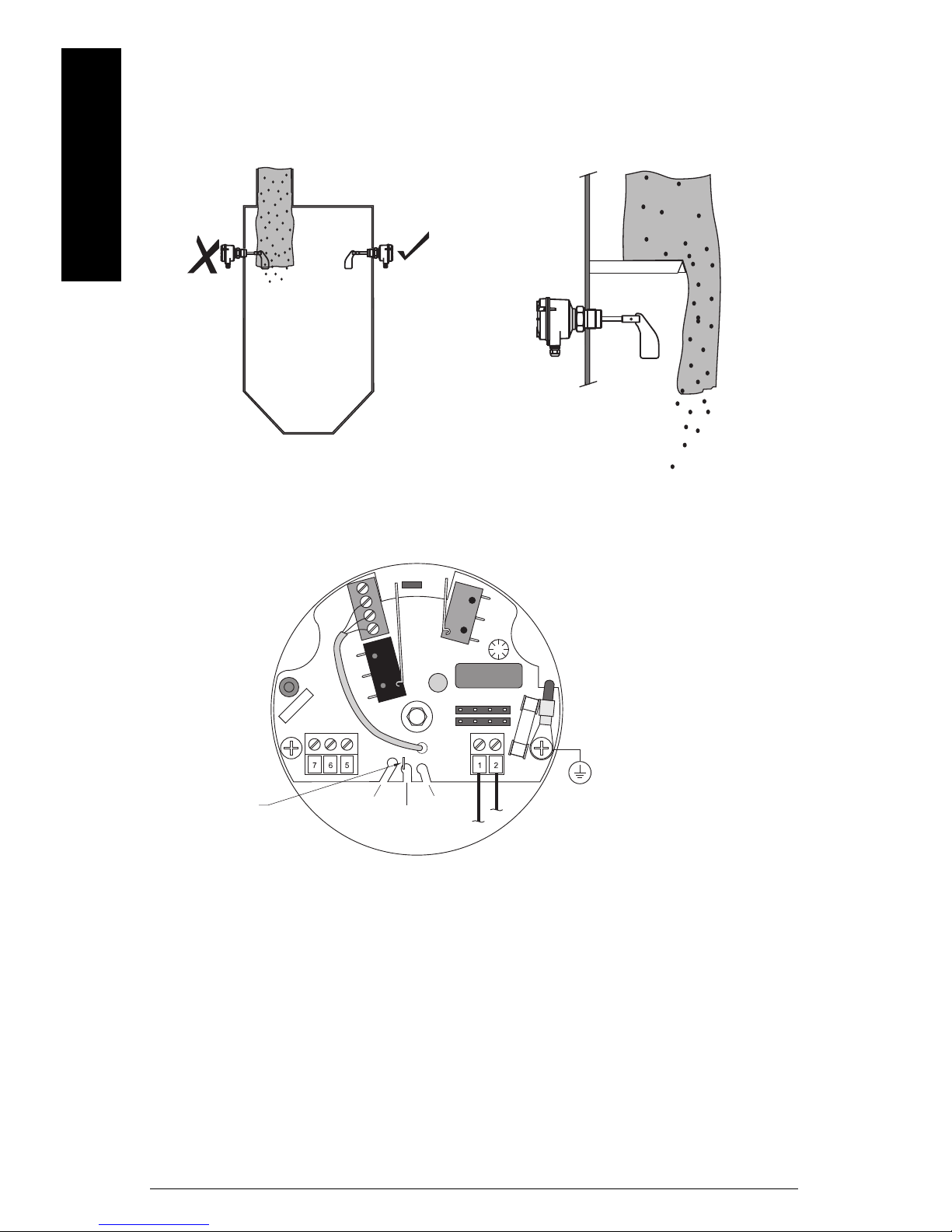
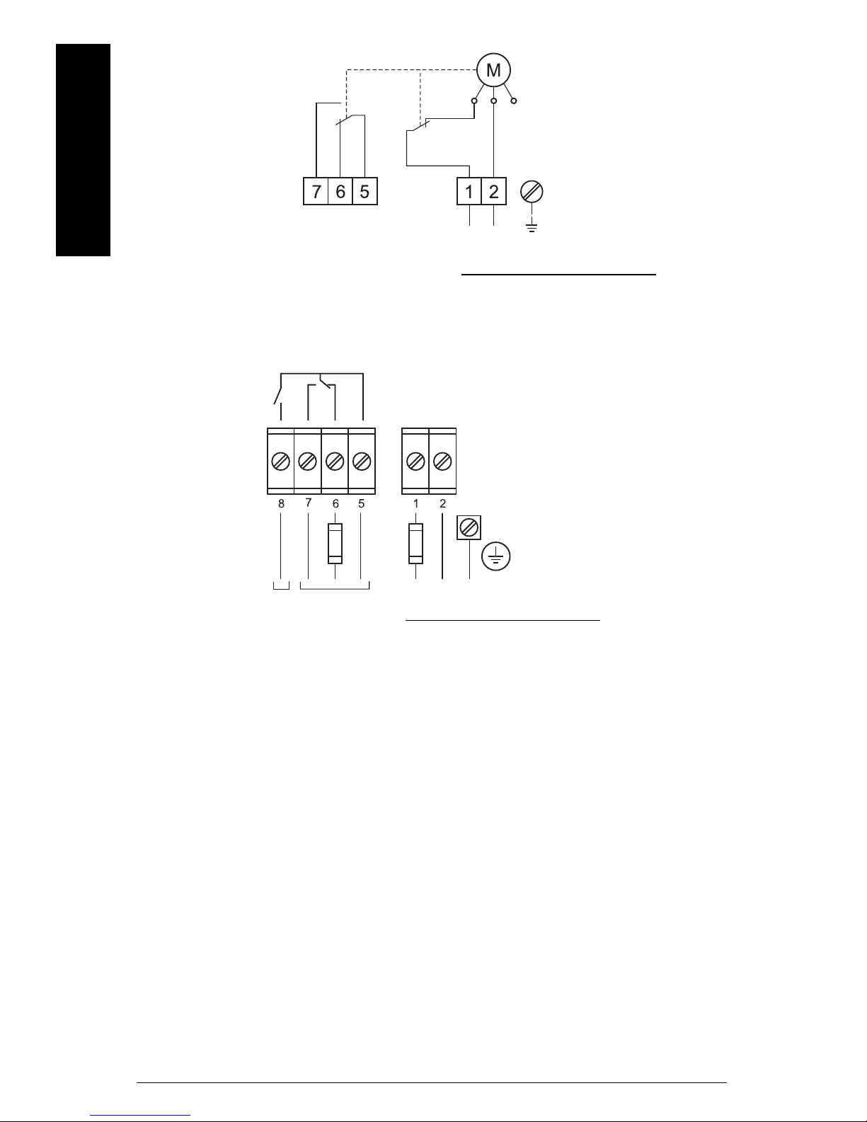
Wiring
voltage
jumper
lamp
protective earth
terminal
WARNINGS:
• Open SITRANS LPS200 only when supply voltage is switched off.
• For switch-selectable voltage version, select correct voltage using
manual voltage jumper before switching on the power supply.
Notes:
• All field wiring must have insulation suitable for at least 250 V AC.
• A disconnect switch shall be in close proximity to the equipment and within easy
reach of the operator.
• Unused cable conduit fittings must be locked with a closing element or plug.
• Commissioning must be done only with a closed device.
• Observe all pertinent rules and regulations of the country of installation.
European Standards
• Cable glands and conduit system for ATEX IECEx (Dust and Gas Hazardous Locations):
Installation according to the regulations of the country where the unit is installed.
Not used entries have to be closed with blanking elements certified for this purpose.
Where available, factory provided parts must be used.
A strain relief must be provided for the field wiring cables, when the device is installed with
the factory provided cable glands.
The diameter of the field wiring cable must match to the clamping range of the cable clamp.
If parts other than the factory provided parts are used, the following must be ensured:
The parts must have an approval adequate to the approval of the level sensor (certificate and
type of protection).
The approved temperature range must be from the minimum ambient temprature of the level
sensor to the maximum ambient temperature of the level sensor increased by 10K.
The parts must be mounted according to the instructions of the supplier.
• Conduit system for FM and CSA (Dust and Gas Hazardous Locations):
General requirements: In addition, the regulations of the country must be observed. The used
flameproof seals and blanking elements must have an adequate type approval and a
temperature range of at least -40 to 80 °C (-40 to 176 °F). In addition, they shall be suitable for
the conditions and correctly installed. Where available, the provided original parts of the
manufacturer must be used.
English
mmmmm
Connections
Switch-selectable voltage, SPDT relay
Select the voltage by placing the voltage jumper over the pins as illustrated below.
7ML19985FS62 SITRANS LPS200 – OPERATING INSTRUCTIONS Page EN-11
mmmmm
24 V DC, 2.5 W
All voltages ± 15 %
alarm output
relay
L
N
+
–
115 V AC, 50 to 60 Hz, 4 VA
230 V AC, 50 Hz, 6 VA
or:
24 V DC, 2.5 W
All voltages ± 15 %
alarm
output
L
N
+
–
24 V or 48 V or 115 V or 230 V AC,
50/60 Hz, 5 VA
or:
signal
output
PE
PE
Switching and timing behaviour:
If the vane is not covered, the
rotating vane shaft will send
pulses at 20 second intervals. In
case of fault, the pulses are
missed. After 30 seconds, the
alarm relay will open.
English
AC or DC version, SPDT relay, fail-safe
Connection Notes
• Before opening the lid, ensure there are no dust deposits around the SITRANS LPS200.
Ensure that the atmosphere around SITRANS LPS200 is settled.
• Use a fuse for the signal output (max. 6 A).
• Make sure the main voltage does not exceed the maximum voltage listed on the
product label and the setting of the voltage selector.
• In case of inexpert handling or handling malpractice, the electric safety of the
device cannot be guaranteed.
• Provide protection for relay contacts to protect the device against spikes if inductive
loads are connected.
Page EN-12 SITRANS LPS200 – OPERATING INSTRUCTIONS 7ML19985FS62
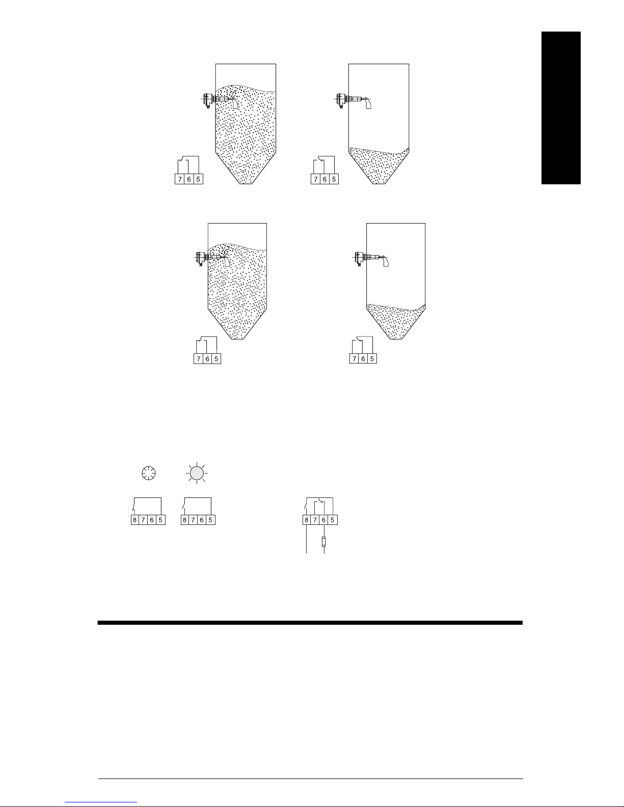
Switching Logic (switch-selectable voltage)
LED
red
LED
green
No
Fault
LED 2
off
Fault
LED 2
red
signal
output
Connection example
Full detector with fail-safe option.
Output signal signals a fault if level reaches
high level switching point, the main voltage
fails, there is a faulty connection, or if the
unit is faulty.
Switching Logic (non-switch selectable)
English
mmmmm
Alarm output - Fail-safe option
Maintenance
SITRANS LPS200 requires no maintenance or cleaning under normal operating
conditions. Under severe operating conditions, the measuring vane may require periodic
cleaning. Brush off any accumulated deposits, taking care not to bend the vane.
7ML19985FS62 SITRANS LPS200 – OPERATING INSTRUCTIONS Page EN-13

Unit Repair and Excluded Liability
All changes and repairs must be done by qualified personnel, and applicable safety
regulations must be followed. Please note the following:
mmmmm
English
• The user is responsible for all changes and repairs made to the device.
• All new components must be provided by Siemens Milltronics Process Instruments Inc.
• Restrict repair to faulty components only.
• Do not re-use faulty components.
Page EN-14 SITRANS LPS200 – OPERATING INSTRUCTIONS 7ML19985FS62
Sicherheitshinweise
Warn- und Hinweistexte müssen besonders beachtet werden. Diese sind grau hinterlegt
vom übrigen Text abgesetzt.
WARNUNG: bezieht sich auf ein Warnsymbol auf dem Produkt und
bedeutet, dass bei Nicht-Einhalt der entsprechenden Vorsichtsmaßnahmen Tod, schwere Körperverletzung und/oder erheblicher Sachschaden eintreten können.
WARNUNG
1
: bedeutet, dass bei Nicht-Einhalt der entsprechenden
Vorsichtsmaßnahmen Tod, schwere Körperverletzung und/oder
erheblicher Sachschaden eintreten können.
VORSICHT: bedeutet, dass bei Nicht-Einhalt der entsprechenden Vorsichtsmaßnahmen erheblicher Sachschaden eintreten kann.
Hinweis:
Betriebsanleitung, auf den besonders aufmerksam gemacht werden soll.
1.
Dieses Symbol wird verwendet, wenn sich kein entsprechendes Vorsichtssymbol auf dem Produkt befindet.
steht für eine wichtige Information über das Produkt selbst oder den Teil der
Sicherheitssymbole
In der Betriebsanleitung:
Auf dem
Produkt
Beschreibung
(Etikett auf dem Produkt: gelber Hintergrund.)
Vorsicht: Details sind in zugehörigen Dokumenten
(Betriebsanleitung) aufgeführt.
Deutsch
mmmmm
Erde (Masseklemme)
Schutzleiterklemme
Das Gerätehandbuch
Hinweise:
• Bitte beachten Sie die Vorschriften für Installation und Betrieb, um eine schnelle,
problemlose Inbetriebnahme, sowie maximale Genauigkeit und Zuverlässigkeit Ihres
SITRANS LPS200 zu gewährleisten.
• Dieses Gerätehandbuch bezieht sich ausschließlich auf den SITRANS LPS200.
Mit Hilfe des vorliegenden Gerätehandbuchs können Sie Ihren SITRANS LPS200 optimal
einstellen. Für Vorschläge und Bemerkungen zu Inhalt, Aufbau und Verfügbarkeit des
Gerätehandbuchs sind wir jederzeit offen.
Bitte richten Sie Ihre Kommentare an techpubs.smpi@siemens.com
mens.com/processautomation finden Sie ein vollständiges Archiv aller Siemens Milltronics Gerätehandbücher.
. Unter www.sie-
7ML19985FS62 SITRANS LPS200 – BETRIEBSANLEITUNG Seite DE-1

SITRANS LPS200, Einleitung
Hinweise:
• Installation, Wartung und Inbetriebnahme müssen durch qualifiziertes, technisches
Personal vorgenommen werden.
• Der SITRANS LPS200 darf nur gemäß den Anweisungen in dieser Betriebsanleitung verwendet werden.
• Dieses Produkt ist für den Einsatz im Industriebereich vorgesehen. Bei Verwendung
in Wohngebieten kann es zu Störungen von verschiedenen Funkanwendungen
kommen.
Der Drehflügelmelder Pointek LPS200 überwacht den Füllstand von Schüttgütern. Das
Drehflügelprinzip eignet sich für die Voll-, Bedarfs- oder Leermeldung bei Materialien wie
Getreide, Futterstoffe, Zement, Kunststoffgranulat und Holzspäne in Silos, Trichtern oder
mmmmm
Deutsch
Lagerbehältern. Mit dem Standardmessflügel misst der Drehflügelmelder bei niedrigen
Schüttdichten von 100 g/l (6.2 lb/ft
und mit dem optionalen Rechteckflügel sogar bis 15 g/l (0.9 lb/ft
3
), mit dem optionalen Klappflügel bis 35 g/l (2.2 lb/ft3)
3
).
SITRANS LPS200, Funktionen
• Mechanische Dichtung
• AC-, DC- oder per Schalter wählbare Spannungsversorgung
• Einzigartige Rutschkupplung. Stößt der Messflügel auf plötzlichen Widerstand, so
verhindert die Rutschkupplung eine Beschädigung interner Bauteile.
• Optionale Laufüberwachung für Alarm bei Fehlerbedingungen oder Ausfall eines
Bauteils
• Verdrehbares Gehäuse
• Optionale Messflügel für den Einsatz bei hoher oder niedriger Schüttdichte bis 15 g/l
• Kurze Ausführung, Ausführung mit Verlängerungsrohr senkrecht (nur Einbau von
oben), Winkelausführung und Seilverlängerungen verfügbar
• Ausführungen für hohe Temperaturen und für hohen Druck verfügbar
• Optionales Verlängerungsset für die kompakte Ausführung verfügbar
SITRANS LPS200, Anwendungsbereiche
• Getreide, Futter, Zement, Plastikgranulat, Holzspäne, Reis, Sojabohnen, usw.
• Materialien mit hoher oder geringer Dichte
Funktionsprinzip
Ein drehgelagerter Messflügel wird von einem Synchrongetriebemotor angetrieben.
Erreicht das Füllgut den Messflügel, so wird dieser angehalten. Es kommt zu einem Kontaktschluss des Relais. Wenn der Messflügel nicht mehr bedeckt ist, dreht er sich erneut
und das Relais kehrt in seinen normalen Zustand zurück.
Der synchronisierte Induktionsmotor ist frei im Gehäuse aufgehängt. Wenn die Drehbewegung durch das Material gebremst wird, entsteht ein Reaktionsdrehmoment, das ein
elektrisches Signal zum Stoppen des Motors ausgibt. Sobald sich der Materialfüllstand
vom Drehflügel entfernt, bringt eine Feder den Motor in seine Betriebsstellung zurück.
Zwei Motorgeschwindigkeiten sind verfügbar: 1 U/min, für Lagertanks
Seite DE-2 SITRANS LPS200 – BETRIEBSANLEITUNG 7ML19985FS62
5 U/min, für höhere Geschwindigkeitsanforderungen des Prozesses
 Loading...