

Siemens SITRANS L Pointek ULS200 Operating Instructions Manual

Pointek ULS200
SITRANS L
Ultrasonic non-contacting switch
Pointek ULS200
Operating Instructions
7ML1510-.....(ULS200)
01/2019
A5E32268616-AB
Introduction
1
Safety notes
2
Description
3
Installing/mounting
4
Operating
5
Application examples
6
Connection
7
Service and maintenance
8
Troubleshooting
9
Technical data
10
Dimension drawings
11
Certificates and support
A

Siemens AG
Digital Industries
Postfach 48 48
90026 NÜRNBERG
GERMANY
Document order number: A5E32268616
Ⓟ 05/2019 Subject to change
Copyright © Siemens AG 2019.
All rights reserved
Legal information
Warning notice system
This manual contains notices you have to observe in order to ensure your personal safety, as well as to prevent
damage to property. The notices referring to your personal safety are highlighted in the manual by a safety alert
symbol, notices referring only to property damage have no safety alert symbol. These notices shown below are
graded according to the degree of danger.
DANGER
indicates that death or severe personal injury will result if proper precautions are not taken.
WARNING
indicates that death or severe personal injury may result if proper precautions are not taken.
CAUTION
indicates that minor personal injury can result if proper precautions are not taken.
NOTICE
indicates that property damage can result if proper precautions are not taken.
If more than one degree of danger is present, the warning notice representing the highest degree of danger will
be used. A notice warning of injury to persons with a safety alert symbol may also include a warning relating to
property damage.
Qualified Personnel
The product/system described in this documentation may be operated only by personnel qualified for the specific
task in accordance with the relevant documentation, in particular its warning notices and safety instructions.
Qualified personnel are those who, based on their training and experience, are capable of identifying risks and
avoiding potential hazards when working with these products/systems.
Proper use of Siemens products
Note the following:
WARNING
Siemens products may only be used for the applications described in the catalog and in the relevant technical
documentation. If products and components from other manufacturers are used, these must be recommended
or approved by Siemens. Proper transport, storage, installation, assembly, commissioning, operation and
maintenance are required to ensure that the products operate safely and without any problems. The permissible
ambient conditions must be complied with. The information in the relevant documentation must be observed.
Trademarks
All names identified by ® are registered trademarks of Siemens AG. The remaining trademarks in this publication
may be trademarks whose use by third parties for their own purposes could violate the rights of the owner.
Disclaimer of Liability
We have reviewed the contents of this publication to ensure consistency with the hardware and software
described. Since variance cannot be precluded entirely, we cannot guarantee full consistency. However, the
information in this publication is reviewed regularly and any necessary corrections are included in subsequent
editions.

Pointek ULS200
Operating Instructions, 01/2019, A5E32268616-AB 3
Table of contents
1 Introduction ................................................................................................................................................ 5
1.1 Operating instructions scope .................................................................................................... 5
1.2 Industrial usage ......................................................................................................................... 5
2 Safety notes ............................................................................................................................................... 6
3 Description ................................................................................................................................................. 7
3.1 Device overview ........................................................................................................................ 7
4 Installing/mounting ..................................................................................................................................... 8
4.1 Mounting location ...................................................................................................................... 8
4.2 Mounting instructions .............................................................................................................. 10
4.3 Instructions specific to hazardous area installations (Reference European ATEX
Directive 94/9/EC, Annex II, 1/0/6) ......................................................................................... 10
5 Operating ................................................................................................................................................. 12
5.1 Startup .................................................................................................................................... 12
5.2 Display/operation status ......................................................................................................... 12
5.3 Quick start ............................................................................................................................... 13
5.4 Operating adjustments ............................................................................................................ 15
5.4.1 Operating adjustments ............................................................................................................ 15
5.4.2 Output function ........................................................................................................................ 17
5.4.3 Setpoints ................................................................................................................................. 19
5.4.4 Relay delay ............................................................................................................................. 19
5.4.5 Relay deadband (reset) .......................................................................................................... 20
5.4.6 Blanking .................................................................................................................................. 21
5.4.7 Range limit .............................................................................................................................. 21
5.4.8 Speed of response .................................................................................................................. 23
5.4.9 Fail-safe mode ........................................................................................................................ 24
5.4.10 Fail-safe timer ......................................................................................................................... 24
5.4.11 Units ........................................................................................................................................ 24
6 Application examples ............................................................................................................................... 25
6.1 Applications ............................................................................................................................. 25
6.2 High level alarm switch ........................................................................................................... 27
6.3 High/low level alarm switch ..................................................................................................... 28
6.4 Low level alarm switch ............................................................................................................ 29
6.5 Dual pump control ................................................................................................................... 30
6.6 Pump control with level alarm ................................................................................................. 31

Table of contents
Pointek ULS200
4 Operating Instructions, 01/2019, A5E32268616-AB
7 Connection .............................................................................................................................................. 32
7.1 Interface ................................................................................................................................. 32
7.1.1 Relay output - DC contact voltage and current limits ............................................................. 34
7.2 Wiring ..................................................................................................................................... 35
7.2.1 Power ..................................................................................................................................... 36
7.2.2 Minimum supply voltage - DC relay version .......................................................................... 36
8 Service and maintenance ........................................................................................................................ 37
8.1 Maintenance ........................................................................................................................... 37
8.2 Unit Repair and Excluded Liability ......................................................................................... 37
9 Troubleshooting ....................................................................................................................................... 38
10 Technical data ......................................................................................................................................... 39
10.1 AC version .............................................................................................................................. 39
10.1.1 Power ..................................................................................................................................... 39
10.1.2 Fuse ....................................................................................................................................... 39
10.1.3 Output .................................................................................................................................... 39
10.2 DC version ............................................................................................................................. 39
10.2.1 Power ..................................................................................................................................... 39
10.2.2 Output .................................................................................................................................... 40
10.3 Operating conditions .............................................................................................................. 40
10.4 Process pressure ................................................................................................................... 40
10.5 Switching range ...................................................................................................................... 40
10.6 Memory .................................................................................................................................. 40
10.7 Programming .......................................................................................................................... 41
10.8 Temperature compensation ................................................................................................... 41
10.9 Display ................................................................................................................................... 41
10.10 Construction ........................................................................................................................... 41
10.11 Approvals ............................................................................................................................... 42
11 Dimension drawings ................................................................................................................................ 43
11.1 Standard ................................................................................................................................. 43
11.2 Sanitary .................................................................................................................................. 45
11.3 Dimension notes .................................................................................................................... 46
A Certificates and support ........................................................................................................................... 47
A.1 Certificates ............................................................................................................................. 47
A.2 Technical support ................................................................................................................... 47

Pointek ULS200
Operating Instructions, 01/2019, A5E32268616-AB 5
1
1.1 Operating instructions scope
This manual outlines the essential features and functions of the device.
1.2 Industrial usage
Note
This product is intended for use in industrial areas. Operation of this equipment in a
residential area may cause interference to several frequency based communications.

Pointek ULS200
6 Operating Instructions, 01/2019, A5E32268616-AB
2
Warning notices must be observed to ensure personal safety as well as that of others, and to
protect the product and the connected equipment. These warning notices are accompanied
by a clarification of the level of caution to be observed.

Pointek ULS200
Operating Instructions, 01/2019, A5E32268616-AB 7
3
WARNING
Improper device modifications
Risk to personnel, system and environment can result from modifications to the device,
particularly in hazardous areas.
• Only carry out modifications that are described in the instructions for the device. Failure
to observe this requirement cancels the manufacturer's warranty and the product
approvals.
Note
The device is to be used only in the manner outlined in this manual, otherwise protection
provided by the equipment may be impaired.
3.1 Device overview
The device is an ultrasonic based process level switch providing high or low switch action on
liquids or solids. The sensor is ETFE or PVDF, allowing it to be used in a wide variety of
industries. The device is used to measure liquids, slurries, and fluid materials, as well as
chemicals and plugged chute detection.
The device contains an ultrasonic transducer and temperature sensing element. The
transducer emits a series of ultrasonic pulses. Each pulse is reflected as an echo from the
material and sensed by the transducer. The device processes the echo using Siemens’
proven Sonic Intelligence techniques. Filtering is applied to help discriminate between the
true echo from the material and the false echoes from acoustical and electrical noises and
agitator blades in motion. The time for the pulse to travel to the material and back is
temperature compensated and then converted into distance for display and relay actuation.
The device is an excellent primary detection device, but should not be used as a backup
device. For backup devices use a contacting technology such as the Pointek CLS200.
Pointek ULS200
8 Operating Instructions, 01/2019, A5E32268616-AB
4
WARNING
Materials of construction compatibility
Materials of construction are chosen based on their chemical compatibility (or inertness) for
general purposes. For exposure to specific environments, check with chemical compatibility
charts before installing.
WARNING
Explosion hazard
Substitution of components may impair suitability for Class I, Division 2 applications.
WARNING
Device functionality
This product can only function properly and safely if it is correctly transported, stored,
installed, set up, operated, and maintained.
WARNING
Selecting bolting and gasket material
The user is responsible for the selection of bolting and gasket materials which will fall within
the limits of the flange and its intended use, and which are suitable for the service
conditions.
4.1 Mounting location
Recommendations:
● Ambient temperature within -40 to +60 °C (-40 to +140 °F), -20 °C (-4 °F) if metal
mounting.
● Easy access for viewing the display and programming via two push buttons.
● An environment suitable to the housing rating and materials of construction.
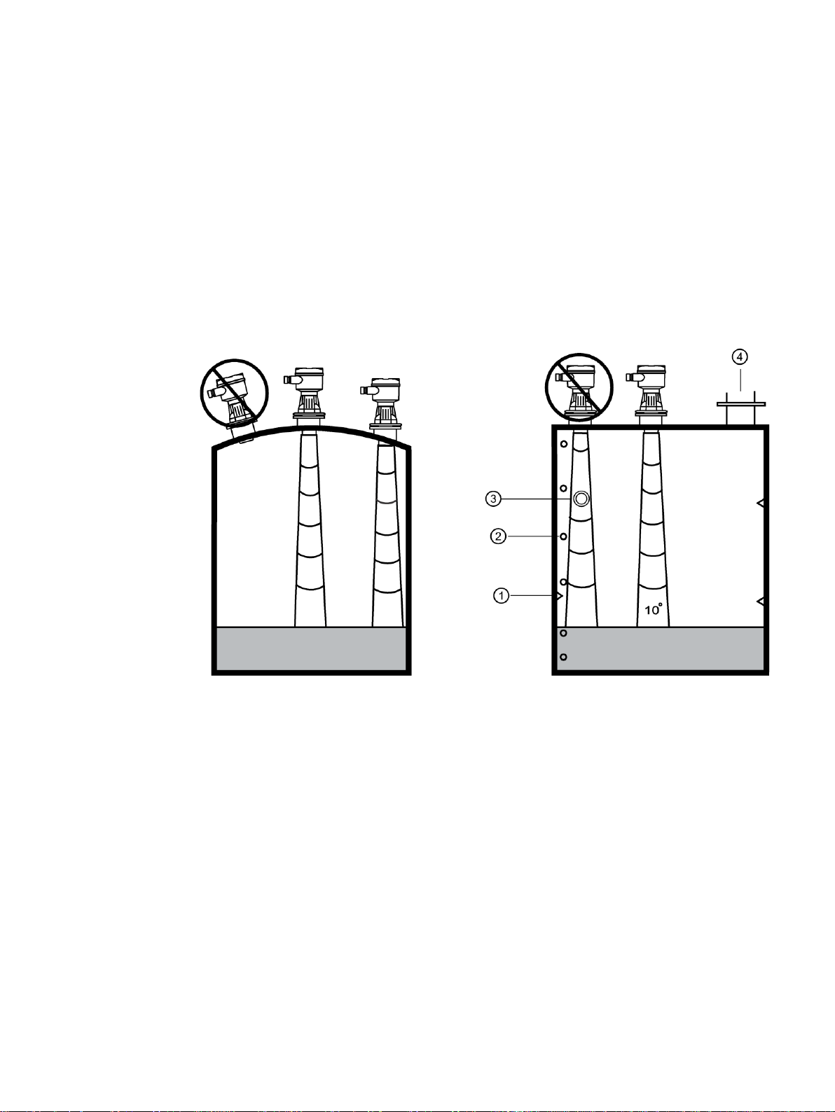
● Keep the sound path perpendicular to the material surface.
Pointek ULS200
Operating Instructions, 01/2019, A5E32268616-AB 9
Precautions:
● Avoid proximity to high voltage or current wiring, high voltage or current contacts, and to
variable frequency motor speed controllers.
● Avoid interference to the sound path from obstructions or from the fill path.
The sound path should be:
● Perpendicular to the monitored surface
● Clear of rough walls, seams, rungs, or other obstructions
● Clear of the fill path
①
Seams
②
Rungs
③
Pipe
④
Fill

Pointek ULS200
10 Operating Instructions, 01/2019, A5E32268616-AB
4.2 Mounting instructions
Note
Ideally, mount the device so that the face of the transducer is at least 250 mm (9.84 inch)
above the highest anticipated level.
The device is available in three thread types: 2" NPT, 2" BSPT, or 2" G.
Before inserting the device into its mounting connection, ensure that the threads are of the
same type to avoid damaging them. Simply screw the device into the process connection,
and hand tighten.
4.3 Instructions specific to hazardous area installations (Reference
European ATEX Directive 94/9/EC, Annex II, 1/0/6)
The following instructions apply to equipment covered by certificate number SIRA
00ATEX1205:
1. The equipment may be used with flammable gases and vapours with apparatus group IIC
and temperature class T5.
2. The equipment is certified for use in an ambient temperature range of -20 to +60 °C
(-4 to +140 °F).
3. The equipment has not been assessed as a safety related device (as referred to by
Directive 94/9/EC Annex II, clause 1.5).
4. Installation and inspection of this equipment shall be carried out by suitably trained
personnel in accordance with the applicable code of practice (EN 60079-14 and
EN 60079-17 in Europe).
5. Repair of this equipment shall be carried out by suitably trained personnel in accordance
with the applicable code of practice (e.g. EN 60079-19 within Europe).
6. Components to be incorporated into or used as replacements in the equipment shall be
fitted by suitably trained personnel in accordance with the manufacturer’s documentation.

Pointek ULS200
Operating Instructions, 01/2019, A5E32268616-AB 11
7. The certification of this equipment relies upon the following materials used in its
construction:
Aluminum alloy T356 T6 (main enclosure) and A356 T6 (lid)
GE Lexan 943A polycarbonate
Two-part epoxy encapsulant
Silicon based coating
Santoprene 111-55 gasket
Master Bond Polysulphide EP21LPT or Dow Corning 3-4207 encapsulant
(transducer)
ETFE (transducer)
Epoxy syntactic foam (transducer)
If the equipment is likely to come in contact with aggressive substances, then it is the
responsibility of the user to take suitable precautions that prevent it from being adversely
affected, thus ensuring that the type of protection is not compromised.
Aggressive substances:
e.g. acidic liquids or gases that may attack
metals, or solvents that may affect polymeric
materials
Suitable precautions:
e.g. regular checks as part of routine inspec-
tions or establishing from the material’s data
sheet that it is resistant to specific chemicals.
8. Equipment Marking:
The equipment marking contains at least the information on the product nameplate,
shown on the inside front cover of this manual.
9. Special Condition for Safe Use: The apparatus must only be supplied from a circuit
containing a suitable rate fuse having a breaking capacity of at least 4 000 A.
Pointek ULS200
12 Operating Instructions, 01/2019, A5E32268616-AB
5
5.1 Startup
With the device correctly installed (or aimed at a wall 0.25 to 5 m away), apply power and
view the startup sequence. It will light all possible LED values, show product revision
number, product model number, and will enter run mode. Then, the display shows the
measurement of the distance from the transducer face to the material level in the units
indicated.
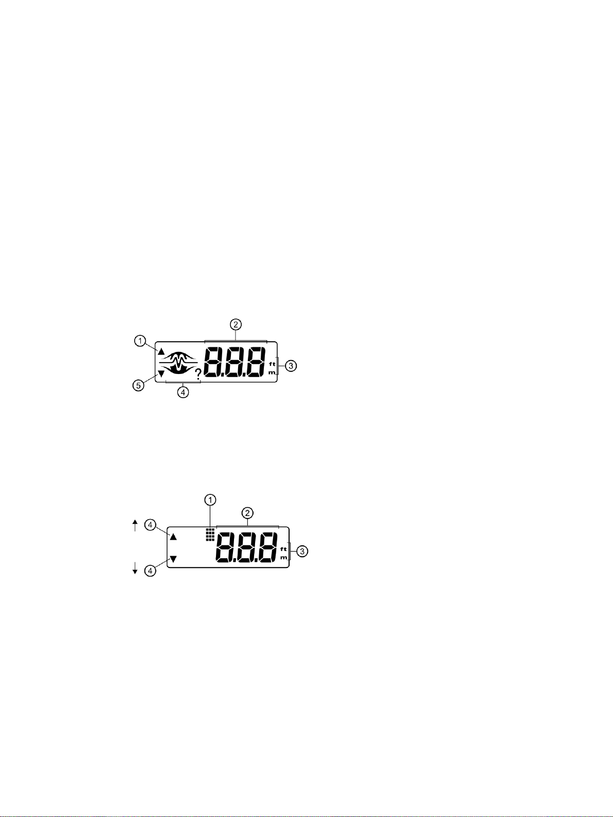
5.2 Display/operation status
①
Output 1
②
Reading
③
Units
④
Operation status
⑤
Output 2
①
Program mode
②
Adjustment value
③
Units
④
Key
Pointek ULS200
Operating Instructions, 01/2019, A5E32268616-AB 13
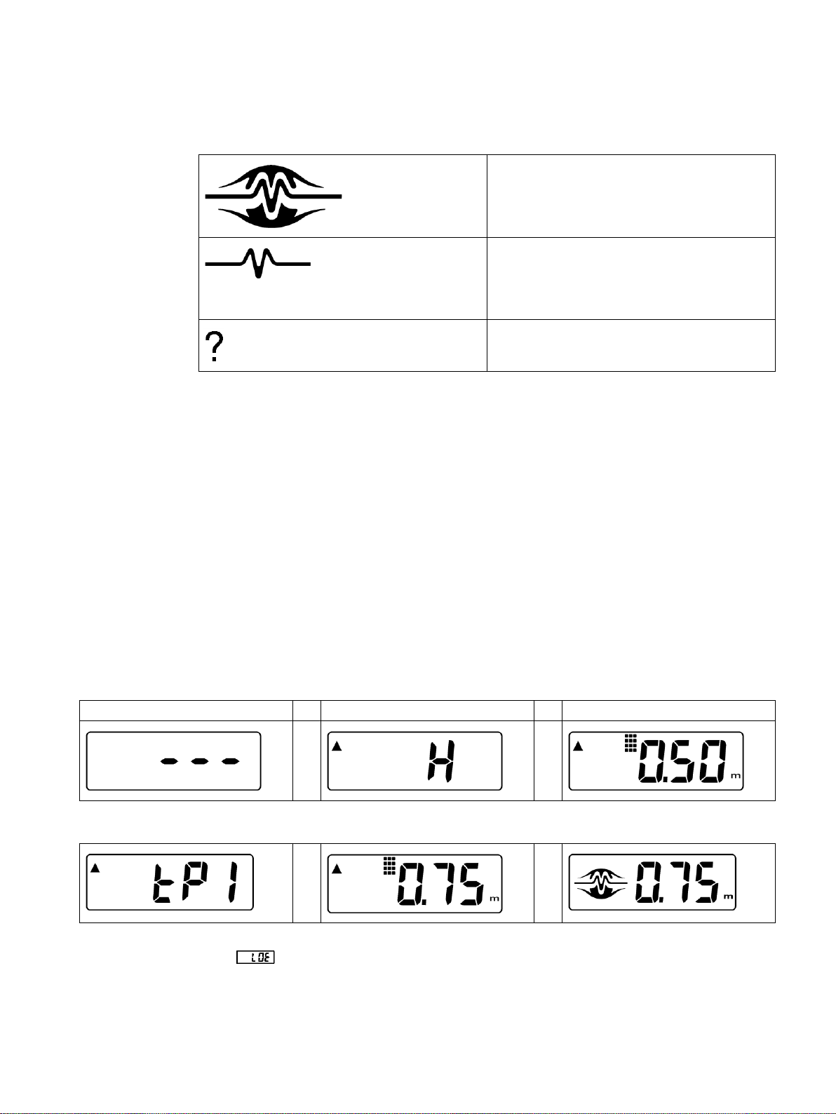
Operation status - run mode
Echoes are valid and within range.
Echoes are lost due to poor conditions or out of
range. This may be typical in applications where
there are deep vessels and the material level is
normally out of range. Refer to Troubleshooting
(Page 38).
Extended loss of echo period. Operation has
gone into fail-safe. Refer to Troubleshooting
(Page 38).
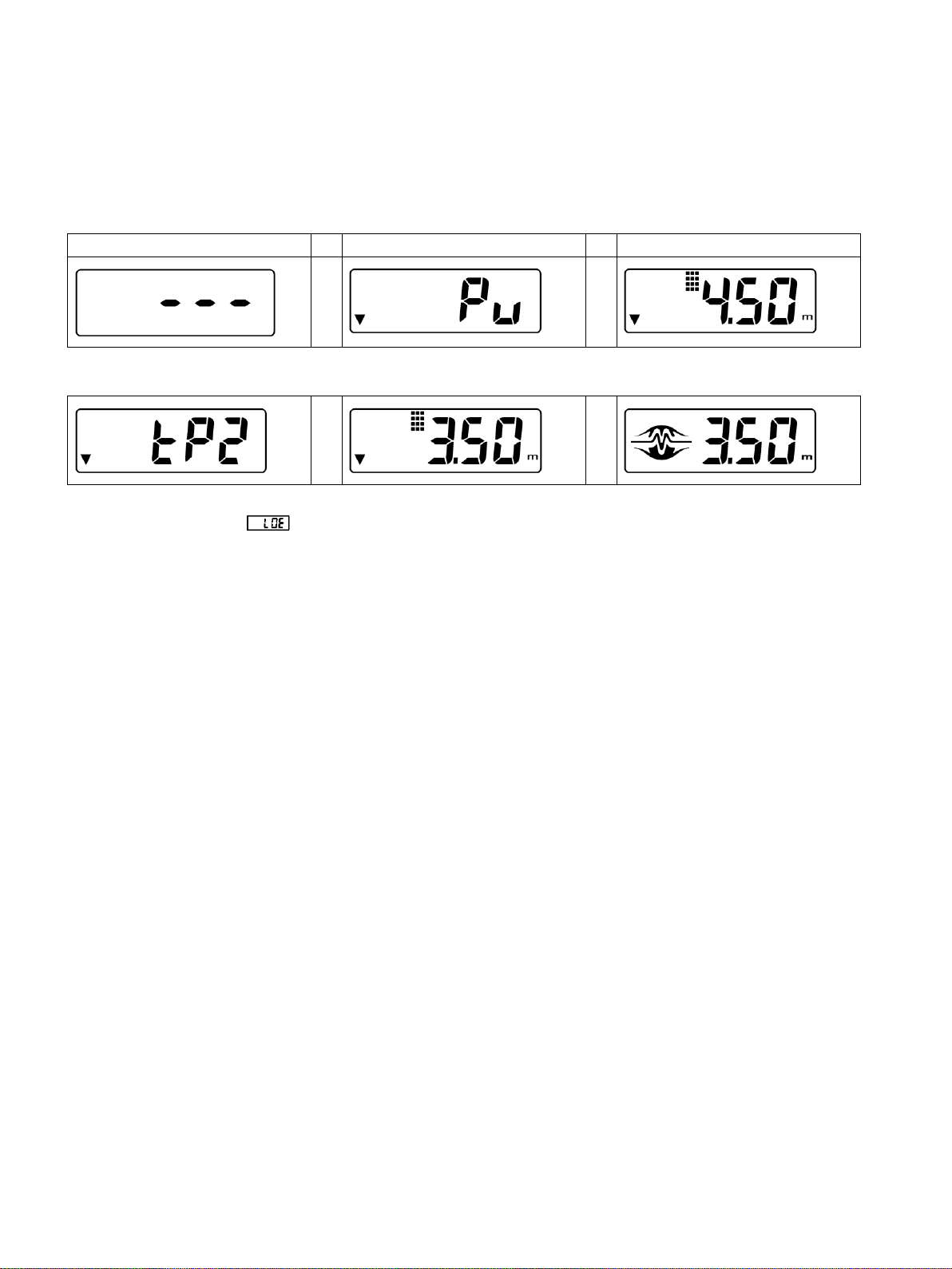
5.3 Quick start
To set a basic high/low application where you can easily adjust the measured distance, use
the method below. The device relays are preset as: relay 1 = alarm 1, high alarm at 0.25 m;
relay 2 = alarm 2, low alarm at 5.00 m.
To change the setpoints by reference method, set the material or target to the distance as
displayed. Press the 1/↑ or 2/↓ key. The display shows the current setpoint function and
value. Press the alarm key a second time so the device changes the setpoint to the value
currently being measured. After viewing or changing the setpoint, the device reverts to the
run mode.
Relay 1
1. Position the unit so that it reads 0.75 m.
2. Press 1/↑
Function display: high alarm
Current setpoint, 0.5 m
⇒ ⇒
3. Press 1/↑
⇒ ⇒
4. Once installed, the unit will register a high alarm at 0.75 m from the sensor face. If Loss of
Echo appears, complete steps 1 to 3 again.
Pointek ULS200
14 Operating Instructions, 01/2019, A5E32268616-AB
Relay 2
1. Position the unit do that it reads 3.50 m.
2. Press 2/↓.
Function display: pump up control
⇒ ⇒
3. Press 2/↓.
⇒ ⇒
4. Once installed, the unit will register a low alarm at 3.50 m from the sensor face. If Loss of
Echo appears, complete steps 1 to 3 again.
Pointek ULS200
Operating Instructions, 01/2019, A5E32268616-AB 15
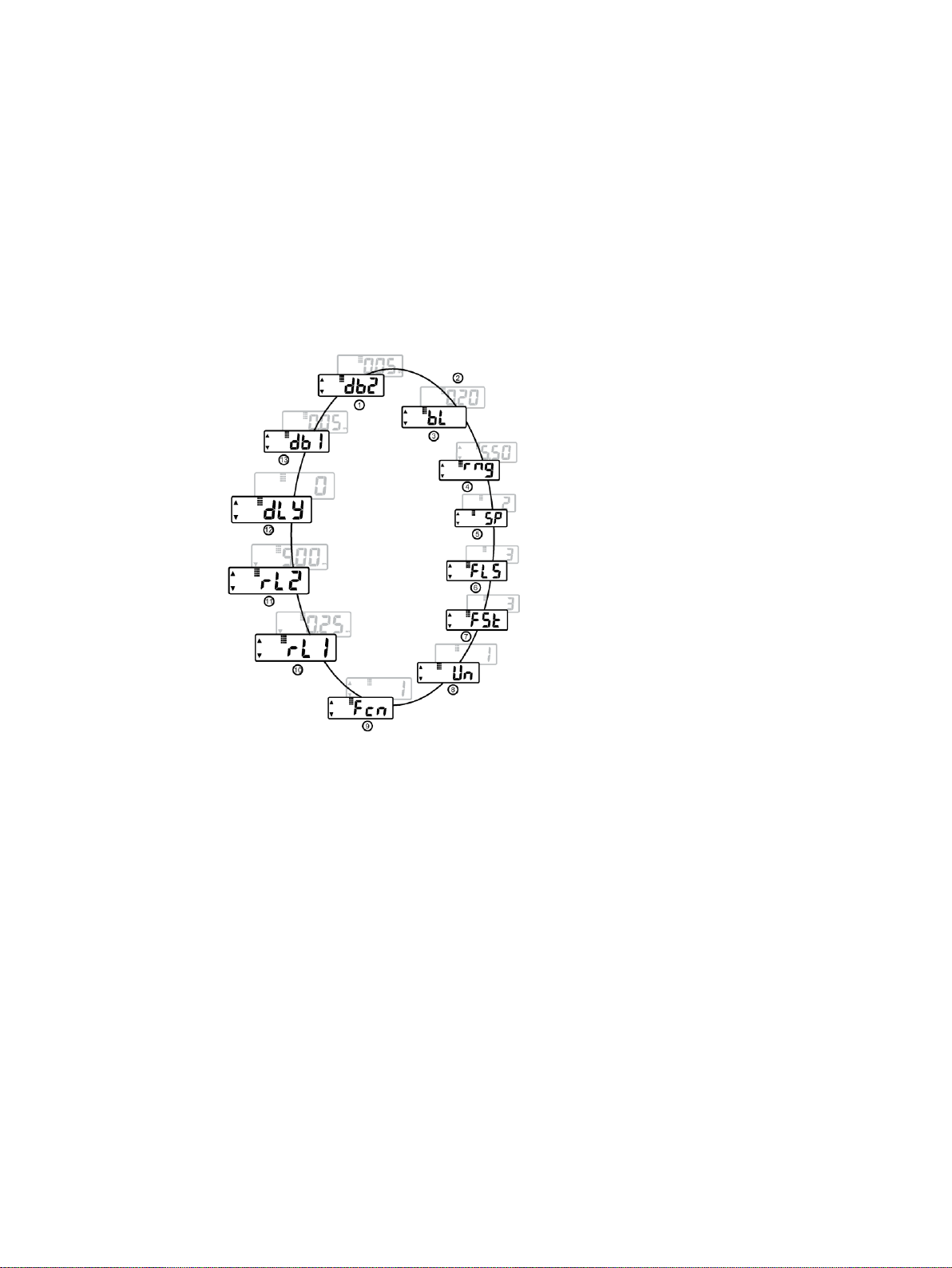
5.4 Operating adjustments
5.4.1 Operating adjustments
To access the operating adjustments, simultaneously press both keys repeatedly until the
desired adjustment is obtained. A viewing period of the adjustment value is initiated. During
this time the value can be changed by pressing either the 'up' or 'down' key. After viewing or
changing, operation automatically reverts to the run mode.
①
Deadband 2
②
On setpoint
③
Blanking
④
Range limit
⑤
Speed of Response
⑥
Fail-safe
⑦
Fail-safe timer
⑧
Units
⑨
Relay function
⑩
Relay 1
⑪
Relay 2
⑫
Delay
⑬
Deadband 1
 Loading...