

Page 1
Additional Operating Instructions
SITRANS F
Vortex flowmeters
SITRANS FX330 Ex-i
09/2018Edition
www.siemens.com/flow
Page 2

CONTENTS
SITRANS FX330
1 Safety instructions 3
1.1 General notes ................................................................................................................... 3
1.2 EU conformity ................................................................................................................... 3
1.3 Approval according to the IECEx scheme ........................................................................ 3
1.4 Safety instructions............................................................................................................ 4
2 Device description 5
2.1 Device description ............................................................................................................ 5
2.2 Marking............................................................................................................................. 5
2.3 Flammable products ........................................................................................................ 7
2.4 Equipment category .........................................................................................................7
2.5 Types of protection ........................................................................................................... 8
2.6 Ambient temperature / temperature classes.................................................................. 8
2.7 Electrical data................................................................................................................. 16
3 Installation 17
3.1 Mounting ......................................................................................................................... 17
3.2 Special conditions........................................................................................................... 18
4 Electrical connections 19
4.1 General notes ................................................................................................................. 19
4.2 Power supply .................................................................................................................. 19
4.3 Inputs / Outputs.............................................................................................................. 20
4.4 Grounding and equipotential bonding............................................................................ 20
4.5 Flow sensor circuits (remote version only) ................................................................... 22
5 Operation 23
5.1 Start-up........................................................................................................................... 23
5.2 Operation ........................................................................................................................ 23
5.3 Electrostatic charge .......................................................................................................23
6 Service 24
6.1 Maintenance ................................................................................................................... 24
6.2 Dismantling .................................................................................................................... 24
7 Notes 26
2
www.siemens.com/flow 09/2018 - A5E39673922-AB
Page 3

SITRANS FX330
1.1 General notes
This additional instruction applies to explosion-protected versions of vortex flowmeters with
protection type intrinsic safety "i", equipment category II 2 G and EPL Gb.
It completes the standard manual for the non-explosion protected versions.
The information given in this instruction contains only the data relevant to explosion protection.
The technical details given in the manual for the non-explosion protected versions remain
unchanged unless they will be excluded or replaced by this instruction.
1.2 EU conformity
The manufacturer declares with the EU declaration of conformity on his own responsibility
conformity with the protection goals of directive 2014/34/EU for use in hazardous areas with gas.
The EU declaration of conformity for the equipment category II 2 G is based on the EU type
examination certificate of the KIWA ExVision:
KIWA 16 ATEX 0044X
KIWA 16 ATEX 0044X
KIWA 16 ATEX 0044XKIWA 16 ATEX 0044X
SAFETY INSTRUCTIONS
1
The "X" after the certificate number refers to special conditions for safe use of the device, which
have been listed in these instructions.
If necessary, the EU type examination certificate can be downloaded from the manufacturer's
website.
1.3 Approval according to the IECEx scheme
Conformity of the vortex flowmeter for use in hazardous areas with gas was tested in accordance
with the "IECEx Certification Scheme for Explosive Atmospheres" according to IEC 60079-0 and
IEC 60079-11.
The number of the IEC certificate is:
IECEx KIWA 16.0021X
IECEx KIWA 16.0021X
IECEx KIWA 16.0021XIECEx KIWA 16.0021X
The "X" after the certificate number refers to special conditions for safe use of the device, which
have been listed in these instructions.
If needed, the IEC certificate can be downloaded from the manufacturer's website.
www.siemens.com/flow09/2018 - A5E39673922-AB
3
Page 4

1
SAFETY INSTRUCTIONS
1.4 Safety instructions
If these instructions are not followed, there is a risk of explosion.
Assembly, installation, start-up and maintenance may only be performed by personnel trained in
explosion protection!
CAUTION!
The operator or his agent is responsible for observing any additional standards, directives or
laws if required due to operating conditions or place of installation.
This applies in particular to the use of easily detachable process connections when measuring
flammable media.
SITRANS FX330
4
www.siemens.com/flow 09/2018 - A5E39673922-AB
Page 5
SITRANS FX330
2.1 Device description
Vortex flowmeters measure and display the flow of flammable and non-flammable gases and
liquids. The signal converter includes either a 4...20 mA signal output with optional HART
communication or a bus connection. There are bus connections available according to the FISCO
model for connecting to the Foundation Fieldbus or Profibus PA. Signal converters with signal
output have a separate binary output and a separate current input.
The SITRANS FX330 remote version consists of the SITRANS FXS300 flow sensor and the
SITRANS FXT030 signal converter.
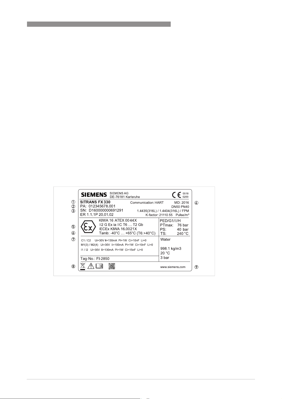
2.2 Marking
The marking of the devices in accordance with the description code is shown on the nameplates
below. On both the compact devices and the remote versions, the main plate is located on the
signal converter housing. On the remote versions there is an additional marking on the flow
sensor.
Compact versions with two signal converters for dual measurement (dual version) are each
marked with a nameplate, which is attached to each of the signal converter housings.
The details relevant to explosion protection are identical on both nameplates.
DEVICE DESCRIPTION
®
2
Figure 2-1: Example of a nameplate for the compact version
1 Device version SITRANS FX330
2 Production order number
3 Serial number
4 Year of manufacture
5 Ex data according to KIWA 16 ATEX 0044X or IECEx KIWA 16.0021X
6 Permissible ambient temperature range
7 Maximum values intrinsically safe circuits
8 Safety instructions, disposal and data matrix
9 Internet address of the manufacturer
www.siemens.com/flow09/2018 - A5E39673922-AB
5
Page 6
2
DEVICE DESCRIPTION
SITRANS FX330
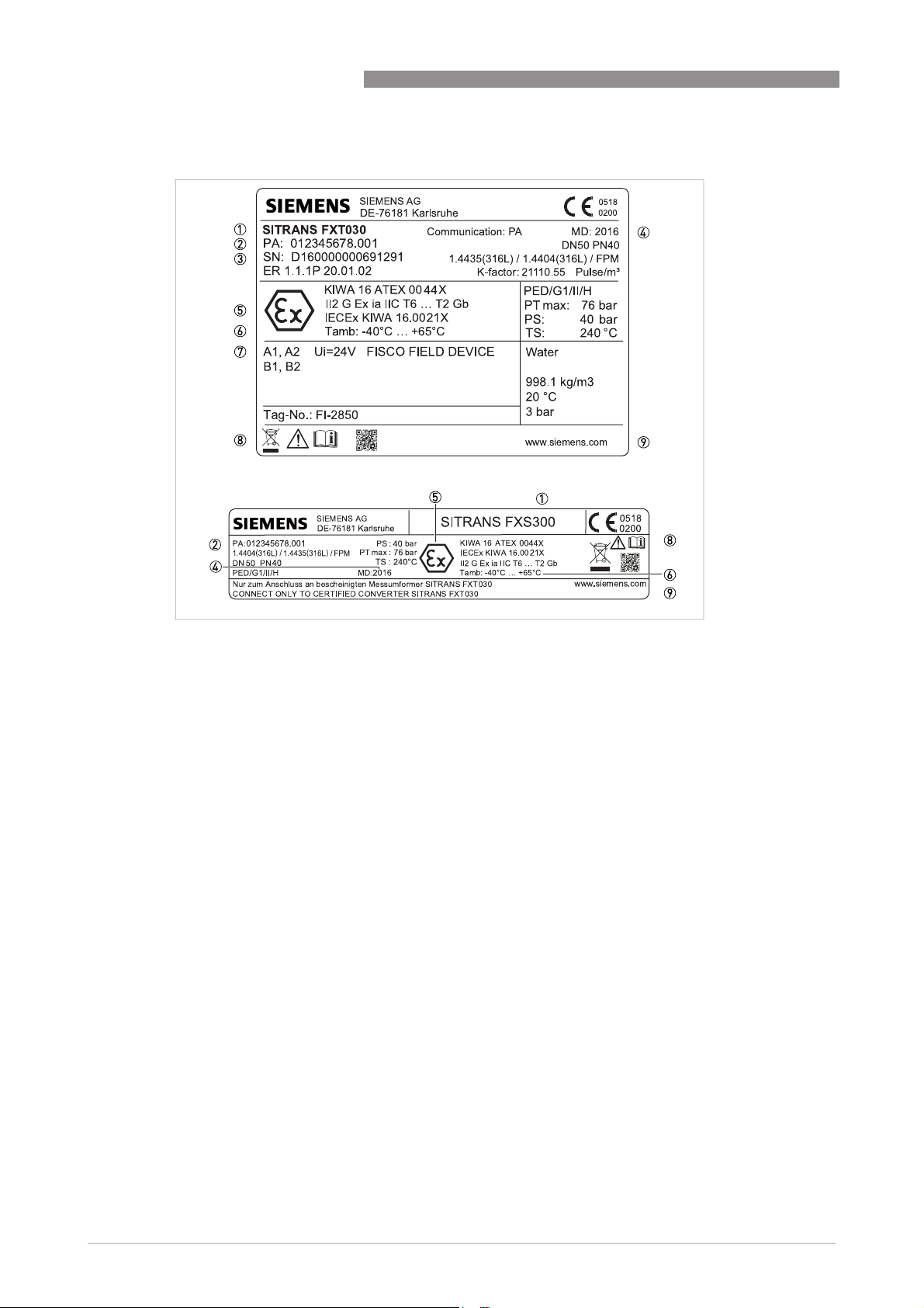
Figure 2-2: Example of the nameplates for the remote version
1 Device version SITRANS FXT030 / SITRANS FXS300
2 Production order number
3 Serial number
4 Year of manufacture
5 Ex data according to KIWA 16 ATEX 0044X or IECEx KIWA 16.0021X
6 Permissible ambient temperature range
7 Maximum values intrinsically safe circuits
8 Safety instructions, disposal and data matrix
9 Internet address of the manufacturer
6
www.siemens.com/flow 09/2018 - A5E39673922-AB
Page 7

SITRANS FX330
2.3 Flammable products
Atmospheric conditions
An explosive atmosphere is a mixture of air and flammable gases, vapours, mists or dusts under
atmospheric conditions.
It is defined by the following values T
11.6...15.9 psi.
Outside of this range, for most mixtures no key figures are available for the ignition behaviour.
Operating conditions
Vortex flowmeters operate outside of atmospheric conditions, which means that explosion
protection according to the ATEX directive, regardless of the zone assignment, is fundamentally
not applicable due to the lack of key safety data for the interior of the measuring section.
CAUTION!
Operation with flammable products is only permitted as long as no explosive fuel/air mixture
builds up on the inside of the flowmeter under operating conditions. The operator is responsible
to ensure that the flowmeter is operated safely in terms of the temperature and pressure of the
products used.
In case of operation with flammable products the measuring units must be included in the
periodic pressure tests of the system.
DEVICE DESCRIPTION
= -20...+60°C / -4...+140°F and P
atm
= 0.8...1.1 bar /
atm
2
2.4 Equipment category
Vortex flowmeters are designed in category II 2 G and EPL Gb according to EN 60079-0 and
EN 60079-11 for use in zone 1. The inside of the measuring unit is also approved for zone 1.
Vortex flowmeters are designed according to the "IECEx-Scheme" according to "Equipment
Protection Level [EPL] Gb".
INFORMATION!
Definition of zone 1 according to EN 1127-1, Appendix B:
An area in which an explosive atmosphere, as a result of the mixture of flammable substances in
the form of gas, steam or mist with air, under normal operation may occasionally occur.
www.siemens.com/flow09/2018 - A5E39673922-AB
7
Page 8

2
DEVICE DESCRIPTION
2.5 Types of protection
The marking is:
ATEX II 2 G Ex ia IIC T6...T2 Gb
IECEx Ex ia IIC T6...T2 Gb
The marking contains the following information:
The marking contains the following information:
The marking contains the following information:The marking contains the following information:
II
II Explosion protection, group II
IIII
2222 Equipment category 2
GGGG Gas explosion protection
Ex ia
Ex ia Intrinsically safe, level of protection "ia"
Ex iaEx ia
IIC
IIC Gas group, suitable for gas groups IIC, IIB and IIA
IICIIC
T6...T2
T6...T2 Temperature class range
T6...T2T6...T2
T6
T6 Temperature class
T6T6
Gb
Gb EPL, suitable for zone 1
GbGb
II 2 G Ex ia IIC T6...T2 Gb
II 2 G Ex ia IIC T6...T2 GbII 2 G Ex ia IIC T6...T2 Gb
(compact version, flow sensor in remote version)
or
II 2 G Ex ia IIC T6 Gb
II 2 G Ex ia IIC T6 Gb
II 2 G Ex ia IIC T6 GbII 2 G Ex ia IIC T6 Gb
(signal converter in remote version)
Ex ia IIC T6...T2 Gb
Ex ia IIC T6...T2 GbEx ia IIC T6...T2 Gb
(compact version, flow sensor in remote version)
or
Ex ia IIC T6 Gb
Ex ia IIC T6 Gb
Ex ia IIC T6 GbEx ia IIC T6 Gb
(signal converter in remote version)
(compact version, flow sensor in remote version)
(signal converter in remote version)
SITRANS FX330
INFORMATION!
In principle, operation is possible in all ranges of the temperature classes T1...T6.
2.6 Ambient temperature / temperature classes
Because of the influence of the temperature of the product, no fixed temperature class is
assigned to vortex flowmeters. The temperature class of these devices is rather a function of the
product temperature and ambient temperature that is present and the specific device version.
The classification is outlined in the following tables.
The tables take into account the following parameters:
• Ambient temperature T
• Product temperature T
• Nominal size DN
• Heat resistance of the connecting cable
amb
m
8
www.siemens.com/flow 09/2018 - A5E39673922-AB
Page 9
SITRANS FX330
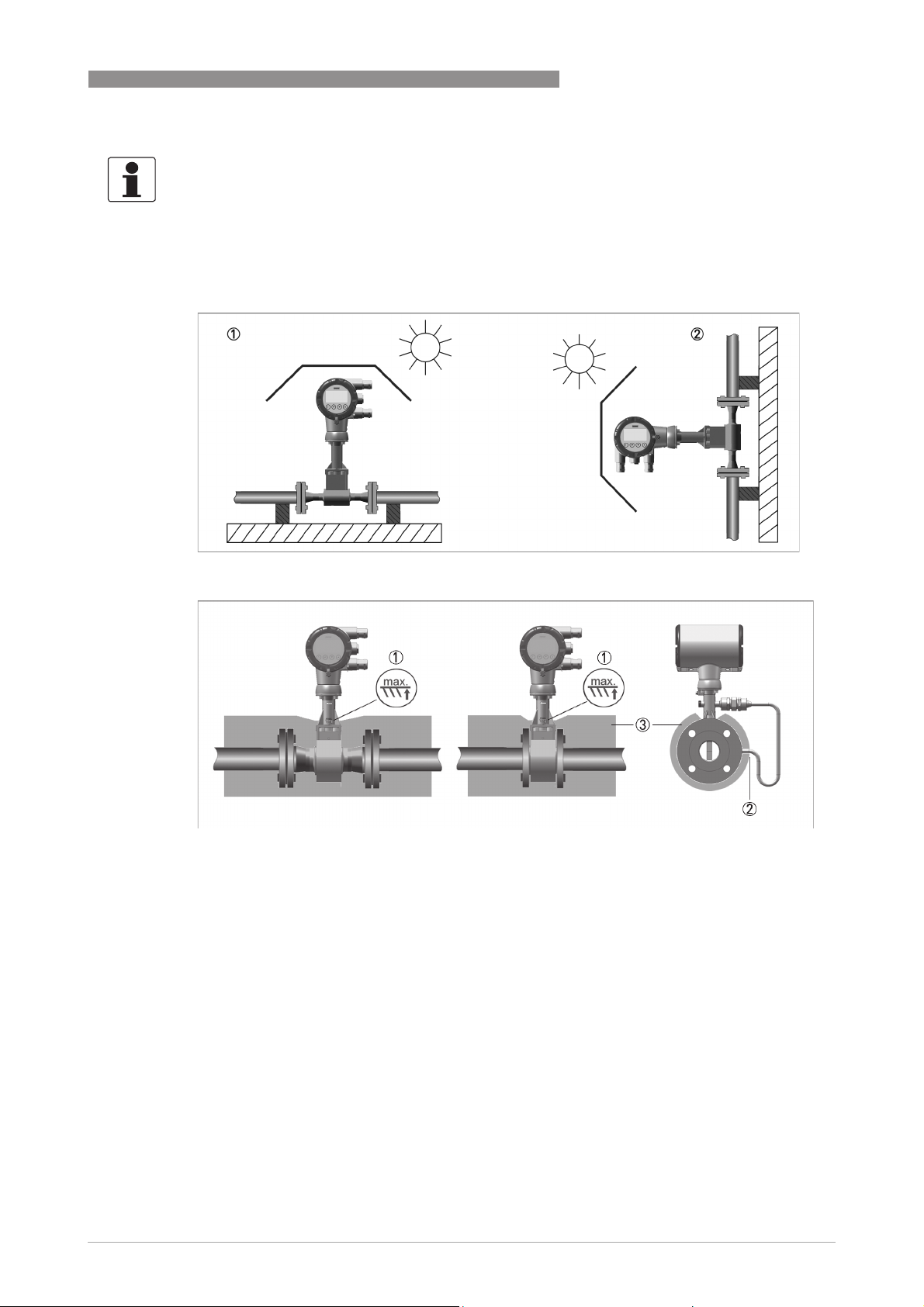
INFORMATION!
The maximum permissible product temperatures listed in the tables are valid under
the following conditions:
•
•
DEVICE DESCRIPTION
2
The measuring device is installed and operated in accordance with the manufacturer's
installation instructions.
It must be ensured that the flowmeter is not heated by the effects of additional heat radiation
(sunshine, neighbouring system components) and thus operated above the permissible
ambient temperature range.
•
Insulation must be limited to the piping. Unobstructed ventilation of the signal converter
must be ensured.
The permitted ambient temperature range is indicated on the nameplate; depending on the
device version it is T
The minimum product temperature is -40°C/ -40°F.
= -40...+65°C / -40...+149°F.
amb
www.siemens.com/flow09/2018 - A5E39673922-AB
9
Page 10

2
DEVICE DESCRIPTION
Max. permissible product and ambient temperatures with signal converter or
connection box mounted above the flow sensor
SITRANS FX330
Temperature class in °C
Temperature class T6 T5 T4 T3 T2
T
in °C 40 60 60 65 40 60 65 40 60 65
amb
Nominal size
DN15…25 85 65 135 135
DN40…50 75 65 135 135
DN80…100 70 65 135
1
DN150...300 80 65 135 135
1 Permanent service temperature of connecting cable and cable entry min. 80°C
135
1
1
1
1
200 200
200 195
200 165
200 200
1
1
1
1
185
165
145
170
1
240 210
1
240 195
1
240
1
240 200
1
Temperature class in °F
Temperature class T6 T5 T4 T3 T2
T
in °F 104 140 140 149 104 140 149 104 140 149
amb
Nominal size
DN15…25 185 149 275 275
DN40…50 167 149 275 275
DN80…100 158 149 275
1
DN150...300 176 149 275 275
1 Permanent service temperature of connecting cable and cable entry min. 176°F
275
1
1
1
1
392 392
392 383
392 329
392 392
1
1
1
1
365
329
293
338
1
464 410
1
464 383
1
464
1
464 392
1
165
329
1
1
1
1
1
1
1
1
185
165
145
170
365
329
293
338
1
1
1
1
1
1
1
1
10
www.siemens.com/flow 09/2018 - A5E39673922-AB
Page 11

SITRANS FX330
DEVICE DESCRIPTION
Max. permissible product and ambient temperatures with signal converter or
connection box mounted at side or underneath the flow sensor
Temperature class in °C
Temperature class T6 T5 T4 T3 T2
T
in °C 40 60 60 65 40 60 65 40 60 65
amb
2
Nominal size
DN15…25 85 90 135 135 200 200 200
DN40…50 85 80 135 135 200 200 200
DN80…100 85 75 135 135
1
200 200
1
DN150...300 85 80 135 135 200 200 200
1 Permanent service temperature of connecting cable and cable entry min. 80°C
200
1
240 240 240
1
240 240 240
1
240 240
1
240 240 240
Temperature class in °F
Temperature class T6 T5 T4 T3 T2
T
in °F 104 140 140 149 104 140 149 104 140 149
amb
Nominal size
DN15…25 185 194 275 275 392 392 392
DN40…50 185 176 275 275 392 392 392
DN80…100 185 167 275 275
1
392 392
1
DN150...300 185 176 275 275 392 392 392
1 Permanent service temperature of connecting cable and cable entry min. 176°F
392
1
464 464 464
1
464 464 464
1
464 464
1
464 464 464
1
1
240
464
1
1
1
1
1
1
1
1
www.siemens.com/flow09/2018 - A5E39673922-AB
11
Page 12

2
DEVICE DESCRIPTION
Max. permissible product and ambient temperatures for devices with painted flow
sensors / signal converters or connection box mounted above the flow sensor
Temperature class in °C
Temperature class T6 T5 T4 T3 T2
T
in °C 40 60 60 65 40 60 65 40 60 65
amb
Nominal size
SITRANS FX330
DN15…25 60 60 120
DN40…50 55 60 120
DN80…100 55 60 110
DN150...300 60 60 120
1 Permanent service temperature of connecting cable and cable entry min. 80°C
1
1
1
1
120
115
105
115
1
1
1
1
120 120
120 120
120 110
120 120
1
120 1120 120
1
115 1120 120
1
105 1120 110
1
115 1120 120
Temperature class in °F
Temperature class T6 T5 T4 T3 T2
T
in °F 104 140 140 149 104 140 149 104 140 149
amb
Nominal size
DN15…25 140 140 248
DN40…50 131 140 248
DN80…100 131 140 230
DN150...300 140 140 248
1 Permanent service temperature of connecting cable and cable entry min. 176°F
1
1
1
1
248
239
221
239
1
1
1
1
248 248
248 248
248 230
248 248
1
248 1248 248
1
239 1248 248
1
221 1248 230
1
239 1248 248
1
1
1
1
1
1
1
1
120
115
105
115
248
239
221
239
1
1
1
1
1
1
1
1
12
www.siemens.com/flow 09/2018 - A5E39673922-AB
Page 13

SITRANS FX330
DEVICE DESCRIPTION
Max. permissible product and ambient temperatures for devices with painted flow
sensors / signal converters or connection box mounted at side or underneath the flow
sensor
Temperature class in °C
Temperature class T6 T5 T4 T3 T2
T
in °C 40 60 60 65 40 60 65 40 60 65
amb
Nominal size
2
DN15…25 85 65 120 120
DN40…50 70 65 120
DN80…100 70 65 120
1
1
DN150...300 75 65 120 120
1 Permanent service temperature of connecting cable and cable entry min. 80°C
120
120
1
1
1
1
120 120 120
120 120
120 120
1
1
120
120
120 120 120
1
120 120 120
1
120 120
1
120 120
1
120 120 120
Temperature class in °F
Temperature class T6 T5 T4 T3 T2
T
in °F 104 140 140 149 104 140 149 104 140 149
amb
Nominal size
DN15…25 185 149 248 248
DN40…50 158 149 248
DN80…100 158 149 248
1
1
DN150...300 167 149 248 248
1 Permanent service temperature of connecting cable and cable entry min. 176°F
248
248
1
1
1
1
248 248 248
248 248
248 248
1
1
248
248
248 248 248
1
248 248 248
1
248 248
1
248 248
1
248 248 248
1
1
1
1
120
120
248
248
1
1
1
1
1
1
1
1
www.siemens.com/flow09/2018 - A5E39673922-AB
13
Page 14

2
DEVICE DESCRIPTION
Max. permissible product and ambient temperatures with signal converter in stainless
steel (bright) or connection box in stainless steel (bright) mounted above the flow
sensor
Temperature class in °C
Temperature class T6 T5 T4 T3 T2
T
in °C 40 60 60 65 40 60 65 40 60 65
amb
Nominal size
SITRANS FX330
DN15…25 70 60 135 135
DN40…50 65 60 135
DN80…100 60 60 135
DN150...300 65 60 135
1 Permanent service temperature of connecting cable and cable entry min. 80°C
1
1
1
135
125
135
1
1
1
1
200 180
200 160
200 1140
200 165
1
1
1
1
155
140
125
145
1
225 180
1
235 160
1
200
1
220 165
1
Temperature class in °F
Temperature class T6 T5 T4 T3 T2
T
in °F 104 140 140 149 104 140 149 104 140 149
amb
Nominal size
DN15…25 158 140 275 275
DN40…50 149 140 275
DN80…100 140 140 275
DN150...300 149 140 275
1 Permanent service temperature of connecting cable and cable entry min. 176°F
1
1
1
275
257
275
1
1
1
1
392 356
392 320
392 284
392 329
1
1
1
1
311
284
257
293
1
437 356
1
455 320
1
392
1
428 329
1
140
284
1
1
1
1
1
1
1
1
155
140
125
145
311
284
257
293
1
1
1
1
1
1
1
1
14
www.siemens.com/flow 09/2018 - A5E39673922-AB
Page 15

SITRANS FX330
DEVICE DESCRIPTION
Max. permissible product and ambient temperatures with signal converter in stainless
steel (bright) or connection box in stainless steel (bright) mounted at side or
underneath the flow sensor
Temperature class in °C
Temperature class T6 T5 T4 T3 T2
T
in °C 40 60 60 65 40 60 65 40 60 65
amb
Nominal size
2
DN15…25 85 60 135 135 200 200 200
DN40…50 85 60 135 135
DN80…100 85 60 135 135
1
1
200 200 200
200 200
1
DN150...300 85 60 135 135 200 200 200
1 Permanent service temperature of connecting cable and cable entry min. 80°C
200
1
240 240 240
1
240 240
1
240 240
1
240 240 240
Temperature class in °F
Temperature class T6 T5 T4 T3 T2
T
in °F 104 140 140 149 104 140 149 104 140 149
amb
Nominal size
DN15…25 185 140 275 275 392 392 392
DN40…50 185 140 275 275
DN80…100 185 140 275 275
1
1
392 392 392
392 392
1
DN150...300 185 140 275 275 392 392 392
1 Permanent service temperature of connecting cable and cable entry min. 176°F
392
1
464 464 464
1
464 464
1
464 464
1
464 464 464
1
1
1
1
225
225
437
437
1
1
1
1
1
1
1
1
www.siemens.com/flow09/2018 - A5E39673922-AB
15
Page 16

2
DEVICE DESCRIPTION
2.7 Electrical data
Signal circuits
Signal circuits
Signal circuitsSignal circuits
The vortex flowmeter signal circuits may only be connected to separate, certified, intrinsically
safe isolating amplifiers or zener barriers connected to separate, intrinsically safe circuits with
the following maximum values per circuit:
SITRANS FX330
Device version Circuit
Maximum values
Terminals
Ui [V] Ii [mA] Pi [W] Ci [nF] Li [μH]
SITRANS FX330
SITRANS FXT030
4...20 mA version
SITRANS FX330
SITRANS FXT030
Foundation Fieldbus version
SITRANS FX330
SITRANS FXT030
Profibus PA version
Flow sensor circuits
Flow sensor circuits
Flow sensor circuitsFlow sensor circuits
Current output 4...20 mA
C1, C2
Binary output
M1, M2, M3, M4
Current input
I1, I2
Bus terminal
A1, A2
B1, B2
FISCO FIELD DEVICE
Bus terminal
A1, A2
B1, B2
FISCO FIELD DEVICE
30 130 1 10 ~ 0
30 100 1 10 ~ 0
30 130 1 15 ~ 0
24 380 5.32 ~ 0 ~ 0
24 380 5.32 ~ 0 ~ 0
For the compact versions, the intrinsically safe flow sensor circuits are designed as internal
circuits.
For the remote versions, the intrinsically safe flow sensor circuits are led through. The
maximum permissible safety values of the flow sensor circuits are listed below:
16
Remote signal converter, flow sensor circuit (terminal 1 to 7, colour-coded)
Remote signal converter, flow sensor circuit (terminal 1 to 7, colour-coded)
Remote signal converter, flow sensor circuit (terminal 1 to 7, colour-coded)Remote signal converter, flow sensor circuit (terminal 1 to 7, colour-coded)
U
=6.65V; Io= 1107 mA; Po= 650 mW; Co=1.5µF; Lo=73µH
o
Remote flow sensor (terminal 1 to 7, colour-coded)
Remote flow sensor (terminal 1 to 7, colour-coded)
Remote flow sensor (terminal 1 to 7, colour-coded)Remote flow sensor (terminal 1 to 7, colour-coded)
=7V; Ii= 1107 mA; Pi= 650 mW; Ci=0; Li=0
U
i
INFORMATION!
The verification of intrinsic safety for the interconnection between the flow sensor an the signal
converter is not necessary, if the cable length does not exceed 50 m / 164 ft and the supplied
cable is used.
www.siemens.com/flow 09/2018 - A5E39673922-AB
Page 17

SITRANS FX330
3.1 Mounting
Mounting and setup must be carried out according to the applicable installation standards
(e.g. EN 60079-14) by qualified personnel trained in explosion protection.
The information given in the manual and these instructions must always be observed.
Vortex flowmeters must be installed in such a way that
• no external forces are affecting the indication unit.
• the device is accessible for any necessary visual inspections and can be viewed from all sides.
• the nameplate is clearly visible.
• it can be operated from a location with secure footing.
CAUTION!
The manufacturer is not liable for any damage resulting from improper use or use other than the
intended purpose. This applies in particular to hazards due to insufficient corrosion resistance
and suitability of the materials in contact with product.
Aligning the signal converter
The signal converter and the connection box for the remote versions may be aligned on the base
or the wall bracket up to a maximum of ± 180 . For this reason, the M4 hexagon socket screw
connecting the base and the signal converter or the connection box must be loosened. Once the
signal converter or the connection box has been turned, it must be screwed back on to the base
again (tightening torque 2 Nm).
INSTALLATION
3
Figure 3-1: Aligning the signal converter
1 M4 hexagon socket screw on connection housing
• De-energise the signal converter.
• Loosen the hexagon socket screw 1.
• Turn the signal converter or the connection box.
• Screw signal converter or connection box back to the base again.
www.siemens.com/flow09/2018 - A5E39673922-AB
17
Page 18

3
INSTALLATION
3.2 Special conditions
Electrostatics
If the installation takes place in hazardous areas of group IIC, the instructions for electrostatics
must be observed. For further information refer to
Thermal and electrical data
Observe the maximum ambient and product temperatures and electrical data. For further
information refer to
Electrical data
on page 16.
Electrostatic charge
Ambient temperature / temperature classes
SITRANS FX330
on page 23.
on page 8 and refer to
18
www.siemens.com/flow 09/2018 - A5E39673922-AB
Page 19

SITRANS FX330
4.1 General notes
The separate intrinsically safe signal circuits are electrically connected in the terminal
compartment of the signal converter. The circuits are designed in protection type "intrinsically
safe" and galvanically isolated from ground (test voltage ≥ 500 V
The intrinsically safe flow sensor circuits are connected in the connection boxes on the wall
bracket and on the flow sensor.
The connecting cables should be selected according to the applicable installation standards
(e.g. EN 60079-14) and the maximum operating temperature.
The connecting cable between the flow sensor and the wall bracket for remote versions is part of
the supply.
• The connecting cables must be fixed and laid so they are sufficiently protected against
damage.
• All cores that are not used must be securely connected to the ground potential of the
hazardous area or carefully insulated against each other and against ground (test voltage
≥ 500 V
• Lay cables so as to ensure that there is sufficient distance between surfaces of the flow
sensor and the connecting cable.
• Supplied blind plugs / cable entries guarantee protection against foreign objects and water
(protection category) IP66/67 according to EN 60529.
• Before connecting or loosening the equipotential bonding cable, ensure there are no
differences in potential.
• Any existing cable shields should be connected to ground according to applicable installation
regulations (EN 60079-14). A terminal in the terminal compartment permits a short way
grounding of the cable shields.
• The outer diameter of the connecting cable must be within the sealing range of the cable
entry (6...12 mm / 0.24...0.47").
• Unused cable entries are to be closed.
eff
ELECTRICAL CONNECTIONS
).
eff
).
4
Ensure that the gaskets and incised gasket ring are tight.
4.2 Power supply
Vortex flowmeters do not require a separate power supply.
The required supply for the built-in electronics is provided via the 4...20 mA current output or the
bus connection.
www.siemens.com/flow09/2018 - A5E39673922-AB
19
Page 20

4
ELECTRICAL CONNECTIONS
4.3 Inputs / Outputs
The terminal assignment is described in the manual. The signal circuits of the vortex flowmeters
may only be connected to certified intrinsically safe slave units or circuits.
For more information refer to chapter "Electrical data".
The current output, the current input and the binary output are designed for connection to a
certified, intrinsically safe circuit in protection type "intrinsic safety Ex ia IIC or Ex ib IIC".
The bus connections are designed for connection to a certified, intrinsically safe circuit in
protection type "intrinsic safety Ex ia IIC or Ex ib IIC" according to the FISCO model.
The current output, the current input and the binary output are reliably separated up to a peak
voltage of 60 V. All signal circuits are electrically isolated from the ground.
4.4 Grounding and equipotential bonding
CAUTION!
Equipotential bonding
Equipotential bonding
Equipotential bondingEquipotential bonding
Vortex signal converters and flow sensors must be included in the on-site equipotential bonding
system according to EN 60079-14! They are connected to the PA terminals.
SITRANS FX330
For compact versions and measuring devices with flange connections, the flow sensor is
conductively connected to the pipeline.
For compact versions and measuring device of the type "sandwich", a separate conductor
connected either to the internal or external PA terminal must be provided to connect to the
equipotential bonding.
Figure 4-1: Ground connection of the compact version
1 Electrical grounding connection on connection piece between the flow sensor and the signal converter
2 Electrical grounding terminal in the housing
20
www.siemens.com/flow 09/2018 - A5E39673922-AB
Page 21

SITRANS FX330
For remote versions with pressure sensor, the connection of the flow sensor can either be made
via the PA connection in the signal converter terminal compartment or via the external PA
connection.
Figure 4-2: Ground connection of the remote version
1 Electrical grounding connection on the flow sensor
2 Electrical grounding connection on the housing of the signal converter
ELECTRICAL CONNECTIONS
4
www.siemens.com/flow09/2018 - A5E39673922-AB
21
Page 22

4
ELECTRICAL CONNECTIONS
4.5 Flow sensor circuits (remote version only)
Observe the following points when connecting the flow sensor to the signal converter:
• Use only the supplied connecting cable (max. length 50 m / 164 ft).
• Before connecting or loosening the equipotential bonding cable, ensure there are no
differences in potential.
• Connect the connecting cable shield to the equipotential bonding of the hazardous area in the
wall bracket. On the flow sensor side, the shield must be carefully isolated from the earth
(test voltage 500 V
the terminal block.
• The terminal compartments of the flow sensor circuits are supplied with a bridge between
the internal PA connection and the terminal with the designation "gnye". This connection
must not be separated.
) and connected via the terminal end to the corresponding connector on
eff
SITRANS FX330
r
n
ye
g
k
b
u
b
rd
g
nye
g
rd
bu
ye
gn
bk
gr
gn ye
Figure 4-3: Connection of the remote version
1 Connection terminal flow sensor
2 Connection terminal signal converter
3 Connection shielding flow sensor
4 Shielding (drain wire and overall shield)
5 Connection shielding signal converter
6 Heat shrink tubing
gr
bk
ye
bu
rd
gn
gnye
22
The flow sensor circuit is designed in protection type "intrinsic safety Ex ia IIC".
www.siemens.com/flow 09/2018 - A5E39673922-AB
Page 23

SITRANS FX330
5.1 Start-up
Start-up is only permitted when the measuring device:
• is correctly installed in the system and connected.
• has been checked for the proper state with regard to its installation and connection
requirements.
The operator of the system has to check prior to start-up, if the start-up was in compliance with
the national regulations for checks.
5.2 Operation
Vortex flowmeters must be operated in such a way that they remain within the maximum and
minimum permissible temperatures and pressures and the electrical limit values.
Vortex flowmeters may only be operated if the equipment parts necessary for safety are effective
in the long run, and are not rendered inoperable during operation.
In case of operation with flammable products the measuring units must be included in the
periodic pressure tests of the system.
OPERATION
5
Operating the converter insert during operation is permitted. To do so, remove the housing
cover. Close the housing cover immediately after adjustment of the converter insert.
Terminal compartments (protection type "intrinsic safety") may be opened even in an energised
state in hazardous area.
Work on electrical connections (e.g. configuration via the HART
an energised state. Terminal compartments must be closed immediately upon completion of the
work.
5.3 Electrostatic charge
In order to avoid ignition hazards due to electrostatic charge, vortex flowmeters may
not be used in areas with:
• processes that generate strong charges,
• mechanical friction and cutting processes,
• spraying of electrons (e.g. in the vicinity of electrostatic painting systems) or
• pneumatically conveyed dust is exposed.
CAUTION!
Electrostatic charging of the housing surface by friction must be avoided.
The devices must not be dry cleaned.
®
interface) is also permitted in
www.siemens.com/flow09/2018 - A5E39673922-AB
23
Page 24

6
SERVICE
6.1 Maintenance
Maintenance work of a safety-relevant nature within the meaning of explosion protection may
only be carried out by the manufacturer, his authorised representative or under the supervision
of authorised inspectors.
SITRANS FX330
Treat cover threads as necessary with the lubricating paint UNIMOLY C220
For systems in hazardous areas, regular tests are required in order to maintain the proper
condition.
The following checks are recommended:
• Check the housing, the cable entries and the feed lines for corrosion and/or damage.
• Checking the measuring unit and the piping connections for leakage.
• Check the measuring unit and the indicator for dust deposits.
• Including the flowmeter in the regular pressure test of the process line.
6.2 Dismantling
Exchanging the built-in equipment
The dismantling and installation is within the responsibility of the operator.
Due to the modular design of the vortex flowmeters, from a safety perspective, the electrical
equipment built into the display can be replaced with identical spare parts. To do so, remove the
housing cover. Close the housing cover immediately after the spare parts are exchanged.
Ensure that the cover seal is tight.
General notes
Exchanging and dismantling should take place in a de-energised state, if at all possible. If that is
not possible, the basic conditions for intrinsic safety (e.g. no grounding or connection of different
intrinsically safe circuits to one another) must be observed during dismantling.
®
.
24
Display
The display can be rotated in 90° increments. It is connected to the connector as shown in the
following figure.
Exchanging the converter insert
It is permitted to replace the entire SITRANS FXT030 converter insert with a brand-new version
identical in construction.
www.siemens.com/flow 09/2018 - A5E39673922-AB
Page 25

SITRANS FX330
Take special note of the following figure and:
• ensure that the construction is the same by checking the nameplates.
• the connecting cable of the flow sensor circuits is to be laid in the cutout provided between
• proper connection of the flow sensor 5 and the display connector 1.
• tighten the mounting screws M4 7 evenly.
SERVICE
the converter insert and housing. Avoid damage such as that caused by crushing.
6
Figure 6-1: Connection of the signal converter module
1 Connector for LC display
2 Service connector
3 SIL jumper
4 Display clamps
5 Connection to the flow sensor
6 Nameplate of the converter insert
7 Fixing screw
Exchanging the entire device
The dismantling and installation is within the responsibility of the operator.
Before disconnecting the electric connecting cable of the device, make sure that all cables
leading to the indication unit are isolated from the ground of the hazardous area. This also
applies to functional earthing conductors (FE) and equipotential bonding conductors (PA).
CAUTION!
•
Pressurised pipes have to be depressurised before removing the measuring unit.
•
In the case of environmentally critical or hazardous products, appropriate safety precautions
must be taken with regard to residual liquids in the measuring unit.
•
New gaskets have to be used when re-installing the device in the piping.
www.siemens.com/flow09/2018 - A5E39673922-AB
25
Page 26

7
NOTES
SITRANS FX330
26
www.siemens.com/flow 09/2018 - A5E39673922-AB
Page 27

SITRANS FX330
NOTES
7
www.siemens.com/flow09/2018 - A5E39673922-AB
27
Page 28

For more information
www.siemens.com/flow
www.siemens.com/processautomation
Siemens AG
Process Industries and Drives
Process Automation
76181 Karlsruhe
Germany
Product
Information
 Loading...