

Siemens SITRANS F Series, SITRANS FUT1010 Quick Start Manual
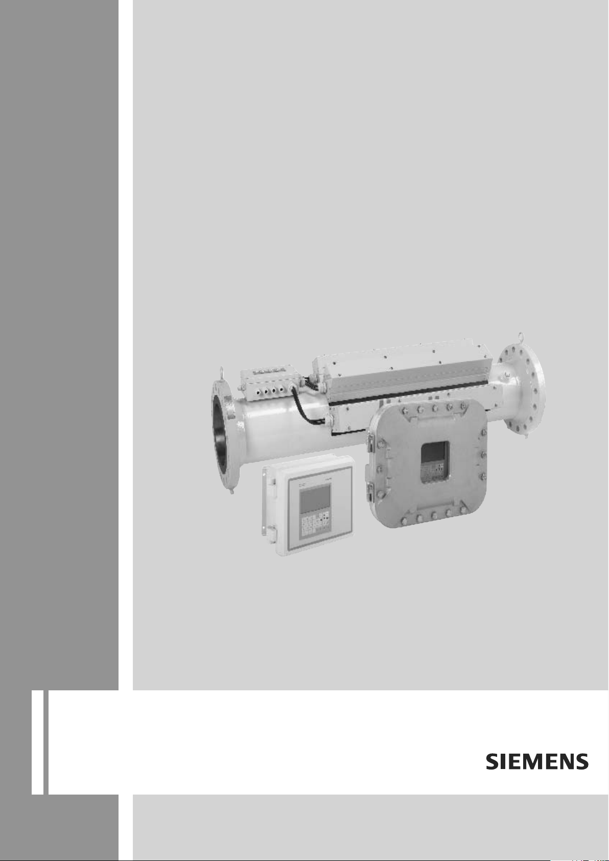
Ultrasonic flowmeters
SITRANS FUT1010 IP65 NEMA 4X & IP66 NEMA 7
7ME362 Liquid Flowmeter
Quick Start - June 2010
SITRANS F

SITRANS F
Introduction
Installing/mounting
Connecting
Commissioning
1
2
3
4
Flowmeters
FUT1010 IP65 NEMA 4X & IP66
NEMA 7 Liquid Quick Start
Operating Instructions
Troubleshooting
Appendix A
5
A
6/2010
A5E02639182A Revision 02
Legal information
Warning notice system
This manual contains notices you have to observe in order to ensure your personal safety, as well as to prevent
damage to property. The notices referring to your personal safety are highlighted in the manual by a safety alert
symbol, notices referring only to property damage have no safety alert symbol. These notices shown below are
graded according to the degree of danger.
DANGER
indicates that death or severe personal injury will result if proper precautions are not taken.
WARNING
indicates that death or severe personal injury may result if proper precautions are not taken.
CAUTION
with a safety alert symbol, indicates that minor personal injury can result if proper precautions are not taken.
CAUTION
without a safety alert symbol, indicates that property damage can result if proper precautions are not taken.
NOTICE
indicates that an unintended result or situation can occur if the corresponding information is not taken into account.
If more than one degree of danger is present, the warning notice representing the highest degree of danger will be
A notice warning of injury to persons with a safety alert symbol may also include a warning relating to property
used.
damage.
Qualified Personnel
The product/system described in this documentation may be operated only by personnel qualified for the specific
task in accordance with the relevant documentation for the specific task, in particular its warning notices and safety
instructions. Qualified personnel are those who, based on their training and experience, are capable of identifying
risks and avoiding potential hazards when working with these products/systems.
Proper use of Siemens products
Note the following:
WARNING
Siemens products may only be used for the applications described in the catalog and in the relevant technical
documentation.
approved by Siemens. Proper transport, storage, installation, assembly, commissioning, operation and
maintenance are required to ensure that the products operate safely and without any problems. The permissible
ambient conditions must be adhered to. The information in the relevant documentation must be observed.
Trademarks
All names identified by ® are registered trademarks of the Siemens AG. The remaining trademarks in this publication
may be trademarks whose use by third parties for their own purposes could violate the rights of the owner.
Disclaimer of Liability
We have reviewed the contents of this publication to ensure consistency with the hardware and software described.
Since variance cannot be precluded entirely, we cannot guarantee full consistency. However, the information in
this publication is reviewed regularly and any necessary corrections are included in subsequent editions.
Siemens AG
Industry Sector
Postfach 48 48
90026 NÜRNBERG
GERMANY
If products and components from other manufacturers are used, these must be recommended or
order number: A5E02639182A
Ⓟ 06/2010
Copyright © Siemens AG 2010.
Technical data subject to change

Table of contents
1 Introduction...................................................................................................................................................5
1.1 Items supplied...............................................................................................................................5
1.2 Safety Notes..................................................................................................................................5
1.3 Pressure Equipment Safety Notes................................................................................................9
2 Installing/mounting......................................................................................................................................11
2.1 Application Guidelines.................................................................................................................11
2.2 Mounting the Transmitter.............................................................................................................11
2.3 Sensor Label Information............................................................................................................13
2.4 Sensor Installation Procedure.....................................................................................................14
3 Connecting.................................................................................................................................................19
3.1 Transmitter Wiring.......................................................................................................................19
3.1.1 Connecting Power.......................................................................................................................19
3.1.2 Connecting Sensor Cables to Transmitter...................................................................................21
3.1.3 Wiring Temperature Sensor to Transmitter.................................................................................22
3.2 Sensor Wiring..............................................................................................................................25
3.2.1 Connecting Sensor Cables to Sensor.........................................................................................25
3.2.2 Wiring Temperature Cable to Sensor..........................................................................................28
4 Commissioning...........................................................................................................................................29
4.1 General requirements..................................................................................................................29
4.2 Commissioning............................................................................................................................29
4.3 Navigating the Menu....................................................................................................................31
5 Troubleshooting..........................................................................................................................................33
5.1 Troubleshooting...........................................................................................................................33
5.2 Alarm Letter Codes and Descriptions..........................................................................................34
A Appendix A.................................................................................................................................................37
A.1 I/O Connections and Wiring.........................................................................................................37
A.2 Technical Data.............................................................................................................................42
Tables
Table 2-1 Hazardous Area Ratings.............................................................................................................17
Table 3-1 TB3 and TB4 Wiring....................................................................................................................25
Table 4-1 Keypad Function Chart...............................................................................................................31
FUT1010 IP65 NEMA 4X & IP66 NEMA 7 Liquid Quick Start
Operating Instructions, 6/2010, A5E02639182A Revision 02
3

Table of contents
Table 5-1 Troubleshooting Tips...................................................................................................................33
Table 5-2 Alarm Codes and Descriptions....................................................................................................34
Table A-1 Connection Diagrams and Part Numbers....................................................................................37
Table A-2 Input/Output Wiring (TB2) - 7ME39400AL03 Expanded I/O Module...........................................37
Table A-3 Input/Output Wiring (TB3) - 7ME39400AL03 Expanded I/O Module...........................................39
Table A-4 Input/Output Wiring (TB4) - 7ME39400AL03 Expanded I/O Module...........................................40
Table A-5 Open Collector User Resistor Recommendations.......................................................................41
Figures
Figure 2-1 Pipe Mounting and Mounting Locations for Transmitter..............................................................12
Figure 2-2 Sample Sensor Label..................................................................................................................14
Figure 2-3 Sensor Installation.......................................................................................................................16
Figure 2-4 Hazard Location Sensor Installation............................................................................................16
Figure 3-1 Input Power Plug (P10) Wiring....................................................................................................19
Figure 3-2 Sensor Cable Connections..........................................................................................................21
Figure 3-3 Analog Input Module Access.......................................................................................................23
Figure 3-4 Temperature Sensor to Junction Box Wiring...............................................................................24
Figure 3-5 Sensor Overview.........................................................................................................................25
Figure 3-6 Sensor Cable Installation.............................................................................................................26
Figure 3-7 Sensor Interconnection Diagram.................................................................................................27
Figure 3-8 Temperature Sensor Board to Junction Box Wiring....................................................................28
Figure 4-1 Splash Screen.............................................................................................................................30
Figure 4-2 KeyPad........................................................................................................................................31
Figure 4-3 Typical Installation Menu Screen.................................................................................................32
Figure A-1 7ME39400AL03 Expanded I/O Module.......................................................................................37
Figure A-2 7ME39400AL03 TB2 Expanded I/O Wiring.................................................................................38
Figure A-3 7ME39400AL03 TB3-I/O Relay Wiring........................................................................................39
Figure A-4 7ME39400AL03 TB4 Expanded I/O Wiring.................................................................................40
Figure A-5 7ME39400AL03 Main Board I/O Wiring......................................................................................41
FUT1010 IP65 NEMA 4X & IP66 NEMA 7 Liquid Quick Start
4
Operating Instructions, 6/2010, A5E02639182A Revision 02
Introduction
This Quick Start is for Siemens SITRANS FUT1010 IP65 (NEMA 4X) liquid flowmeters. The
flowmeter
and is shipped with factory installed sensors and preset Site Setups.
1
includes the Transmitter and the Sensor Body with the TransLocTM Mounting System
CAUTION
The flowmeter menu parameters are pre-set at the factory. It is not recommended to change
the factory preset parameters. If changes are desired, use care when changing Site Setup
and Transducer Install menu cells.
Note
Quick Start applies to the following FUT1010 IP65 NEMA 4X operating systems: Version
This
3.03.00 and later / Version 5.03.00 and later.
1.1 Items supplied
●
SITRANS F Flowmeter (Transmitter and Sensor Body)
● SITRANS F literature CD
● Quick Start
● For additional items refer to your packing slip.
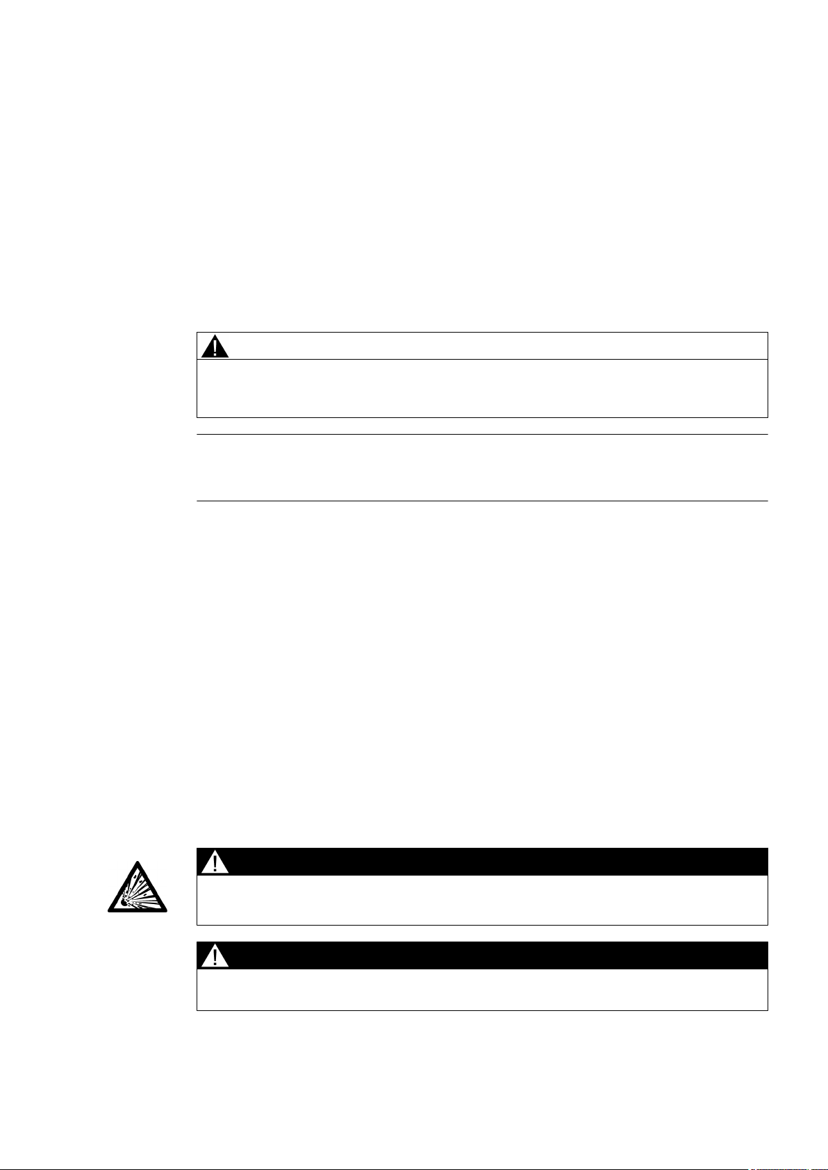
1.2 Safety Notes
Safety Information for Hazardous Areas
DANGER
Explosion Hazard. Will Cause Death, Serious Injury or Property Damage.
Restrict use and repair to qualified personnel.
FUT1010 IP65 NEMA 4X & IP66 NEMA 7 Liquid Quick Start
Operating Instructions, 6/2010, A5E02639182A Revision 02
DANGER
Death or severe personal injury and/or equipment and property damage will result if proper
Hazardous (Classified) Locations installation precautions are not taken.
5
Introduction
1.2 Safety Notes
DANGER
The use of unauthorized parts in the repair of the equipment, tampering by unqualified
personnel, or operation with the cover open in a Hazardous (Classified) Location will result
dangerous conditions which will cause death, serious injury, and/or equipment and property
in
damage.
Follow all safety instructions contained or referenced herein.
DANGER
Explosion hazard
Death or severe personal injury and/or equipment and property damage will result due to
improper installation or use of this equipment when located in a Hazardous (Classified)
Location.
● Install as directed.
● Disconnect power source before servicing.
● Keep cover closed when equipment is operating.
WARNING
Qualified personnel
This flowmeter system may only be set up and used in conjunction with this document and
the
instructions on the electronic media provided. Installation, maintenance and operation of
the flowmeter system may only be performed by qualified personnel. Within the context of
this Document, qualified persons are defined as persons who have the skills and knowledge
related to the construction and operation of the electrical equipment and installations and
have received safety training to recognize and avoid the potentially explosive hazards
involved.
Qualified personnel posses the following qualifications
1. Is trained and authorized to energize, de-energize, clear, ground and tag circuits and
equipment in accordance with established safety practices.
2. Is trained in the proper care and use of protective equipment such as rubber gloves, hard
hat, safety glasses or face shields, flash clothing, etc., in accordance with established
safety practices.
3. Is trained in rendering first aid.
Note
This document does not purport to cover all details or variations in equipment, or to provide
for every possible contingency to be met in connection with installation, operation or
maintenance. Should further information be desired or should particular problems arise,
are not covered sufficiently for the purchaser's purposes, the matter should be referred
which
to the local Siemens sales office (www.automation.siemens.com/partner). The contents of
this Document shall not become part of or modify any prior or existing agreement,
commitment or relationship. The sales contract contains the entire obligation of Siemens.
The warranty contained in the contact between the parties is the sole warranty of Siemens.
Any statements contained herein do not create new warranties or modify the existing warranty.
FUT1010 IP65 NEMA 4X & IP66 NEMA 7 Liquid Quick Start
6
Operating Instructions, 6/2010, A5E02639182A Revision 02

Safety Information for Hazardous Areas
Note
Ratings under this heading apply to specific model families.
Check Your Model Number: FUT1010, 7ME362x.
FM-CSA installation
Read, understand and follow all safety instructions on the electronic media provided. This
equipment is rated for use in hazardous (classified) locations as stated below and must be
installed
according to the 1010-304 installation drawing provided on the media. Failure to install
the equipment in the prescribed manner will result in unsafe operation. Follow all local
jurisdictional safety codes when operating this equipment. When properly installed the
equipment meets the following FM – CSA ratings.
Transmitter
● Intrinsically safe connections Class I and II, Division 1, Groups A, B, C, D, E, F and G;
● Nonincendive for Class I, Division 2, Groups A, B, C and D;
Introduction
1.2 Safety Notes
● Suitable for Class II, Division 2, Groups E, F and G outdoor (Type 4X), Class III (CSA only)
● Temperature code T5 at an ambient of 40°C
Sensors
● Intrinsically safe Class I and II, Division 1, Groups A, B, C, D, E, F and G;
● Nonincendive for Class I, Division 2, Groups A, B, C and D;
● Suitable for Class II, Division 2, Groups E, F and G outdoor (Type 4X), Class III (CSA only)
● Temperature code T6 at an ambient of 40°C
ATEX installation
Read, understand and follow all safety instruction on the electronic media provided. This
equipment complies with Directive 94/9/EC and is rated for use in potentially explosive
atmospheres. The equipment markings are shown and explained below. Equipment must be
installed according to the 1010-389 installation drawing provided on the media. Failure to install
the equipment in the prescribed manner will result in unsafe operation. Follow all regional
safety laws when operating this equipment. When properly installed the equipment meets the
following ATEX ratings as stated in EC-Type Examination Certificate KEMA03ATEX1134
Transmitter Markings and Explanations
●
II (1) G [Ex ia] IIC – Transmitter located in the non-hazardous area with intrinsically safe
circuits of category Ex ia, which can be connected to Category 1 Sensors
●
II 3 (1) G Ex nC [ia] IIC T5 – Category 3 Transmitter located in Zone 2 for use in potentially
explosive atmosphere containing gases with intrinsically safe circuits of category Ex ia,
which can be connected to Category 1 Sensors in Zone 0
● IP65
– Ingress protection against solid bodies, rating of dust-tight and against liquid, rating
of water jets
FUT1010 IP65 NEMA 4X & IP66 NEMA 7 Liquid Quick Start
Operating Instructions, 6/2010, A5E02639182A Revision 02
7

Introduction
1.2 Safety Notes
Sensor Markings and Explanations
●
II 1 G Ex ia IIC T5 – Category 1 Sensors located in Zone 1 hazardous area with
intrinsically safe circuits of category Ex ia for use in potentially explosive atmosphere
containing gases
● IP65 – Ingress protection against solid bodies, rating of dust-tight and against liquid, rating
of water jets
Safety Information for Hazardous Areas
Note
Ratings under this heading apply to specific model families.
Check Your Model Number: FUT1010, 7ME362x.
FM-CSA installation
Read, understand and follow all safety instruction on the electronic media provided. This
equipment is rated for use in hazardous (classified) locations as stated below and must be
installed
according to the 1010-443 installation drawing provided on the media. Failure to install
the equipment in the prescribed manner will result in unsafe operation. Follow all local
jurisdictional safety codes when operating this equipment. When properly installed the
equipment meets the following FM – CSA ratings:
Transmitter
● Explosionproof for Class I, Division1, Groups B, C, D;
● Dust-ignitionproof for Class II, Division 1, Groups E, F and G;
● Intrinsically safe connections for Class I and II, Division 1, Groups A, B, C, D, E, F and G;
● Nonincendive for Class I, Division 2, Groups A, B, C and D;
● Suitable for Class II, Division 2, Groups E, F and G outdoor (Type 4X), Class III (CSA only)
Sensors
● Intrinsically safe connections Class I and II, Division 1, Groups A, B, C, D, E, F and G;
● Nonincendive for Class I, Division 2, Groups A, B, C and D;
● Suitable for Class II, Division 2, Groups E, F and G outdoor (Type 4X), Class III (CSA only)
● Temperature code T6 at an ambient of 40°C
ATEX installation
Read, understand and follow all safety instruction on the electronic media provided. This
equipment is rated for use in explosive atmospheres as stated below and must be installed
according to the 1010-464 installation drawing provided on the media. Failure to install the
equipment in the prescribed manner will result in unsafe operation. Follow all regional safety
laws when operating this equipment. When properly installed the equipment meets the
following ATEX ratings as stated in EC-Type Examination Certificate KEMA03ATEX1134
FUT1010 IP65 NEMA 4X & IP66 NEMA 7 Liquid Quick Start
8
Operating Instructions, 6/2010, A5E02639182A Revision 02
Introduction
1.3 Pressure Equipment Safety Notes
Transmitter Markings and Explanations
●
II (1) G [Ex ia] IIC– Transmitter located in the non-hazardous area with intrinsically safe
circuits of category Ex ia, which can be connected to Category 1 Sensors for use in
potentially explosive atmosphere containing gases
●
II 3 (1) G Ex nC [ia] IIC T5 (Tamb = 0° To + 60°C) – Category 3 Transmitter located in
Zone 2 hazardous area with intrinsically safe circuits of category Ex ia, which can be
connected to Category 1 Sensors in Zone 0 for use in potentially explosive atmosphere
containing gases
●
II 2 (1) G Ex d [ia IIC] IIB T5 (Tamb = 0° To + 50°C) – Category 2 Transmitter located
in Zone 1 hazardous area with intrinsically safe circuits of category Ex ia, which can be
connected to Category 1 Sensors for use in potentially explosive atmosphere containing
gases
● IP66 – Ingress protection against solid bodies, rating of dust-tight and against liquid, rating
of heavy seas
Sensor Markings and Explanations
●
II 1 G Ex ia IIC T5 – Category 1 Sensors located in Zone 1 hazardous area with
intrinsically safe circuits of category Ex ia for use in potentially explosive atmosphere
containing gases
● IP65 – Ingress protection against solid bodies, rating of dust-tight and against liquid, rating
of water jets
1.3 Pressure Equipment Safety Notes
WARNING
HOT SURFACE - External Sensor temperature can exceed 93°C (200°F).
WARNING
Exceeding rated pressure identified as MAOP may cause Sensor failure.
WARNING
User is responsible for ensuring that all Sensor ports are properly sealed.
WARNING
It is the responsibility of the user to account for any potential confusion or misuse of gas
equipment with liquid equipment or visa versa.
WARNING
Materials of construction are chosen based on their chemical compatibility (or inertness) for
general
purposes. For exposure to specific environments, check with chemical compatibility
charts before installing.
FUT1010 IP65 NEMA 4X & IP66 NEMA 7 Liquid Quick Start
Operating Instructions, 6/2010, A5E02639182A Revision 02
9
Introduction
1.3 Pressure Equipment Safety Notes
WARNING
Sensors have been designed to account for loads to internal pressures in accordance with
ASME codes. It is the responsibility of the user to access and account for other externally
applied loads due to earthquakes, pipe movement and other environmental conditions.
WARNING
During vertical Sensor installation use appropriate equipment to ensure safety.
WARNING
The user is responsible for the selection of bolting and gasket materials which will fall within
limits of the flange and its intended use and which are suitable for the service conditions.
the
WARNING
Never attempt to loosen, remove, or disassemble process connection or instrument housing
while contents are under pressure.
WARNING
Remove all condensation from Sensor before installing into line.
10
FUT1010 IP65 NEMA 4X & IP66 NEMA 7 Liquid Quick Start
Operating Instructions, 6/2010, A5E02639182A Revision 02

Installing/mounting
2.1 Application Guidelines
Basic Requirements
Avoid vertical pipes flowing in a downward direction.
●
● Select a location with the longest straight run of pipe.
● Identify upstream piping configuration (elbow, reducer, etc.).
2
Additonal Requirements for Liquid Applications
● Avoid pressure reduction components upstream.
Note
Flowmeter
flow.
●
Pipe must be full to achieve proper operation.
Application Data menu [Pipe Config] parameter is preset for [Fully Developed]
2.2 Mounting the Transmitter
Wall Mounting
The transmitter can be mounted on any wall surface including wood, metal or concrete. Use
the appropriate bolts and screws as needed for your mounting application and adhere to local
codes. (See figure below for mounting bracket locations.)
Pipe Mounting
For installation on pipe use Pipe Mount Kit CQO:1012NMB-1 (optional - see catalog). See
FUT1010 IP65 NEMA 4X & IP66 NEMA 7 Liquid Quick Start
Operating Instructions, 6/2010, A5E02639182A Revision 02
figure below.
Note
Pipe mounting kit CQO:1012NMB-1 is not available for NEMA 7 enclosures.
11
Installing/mounting
2.2 Mounting the Transmitter
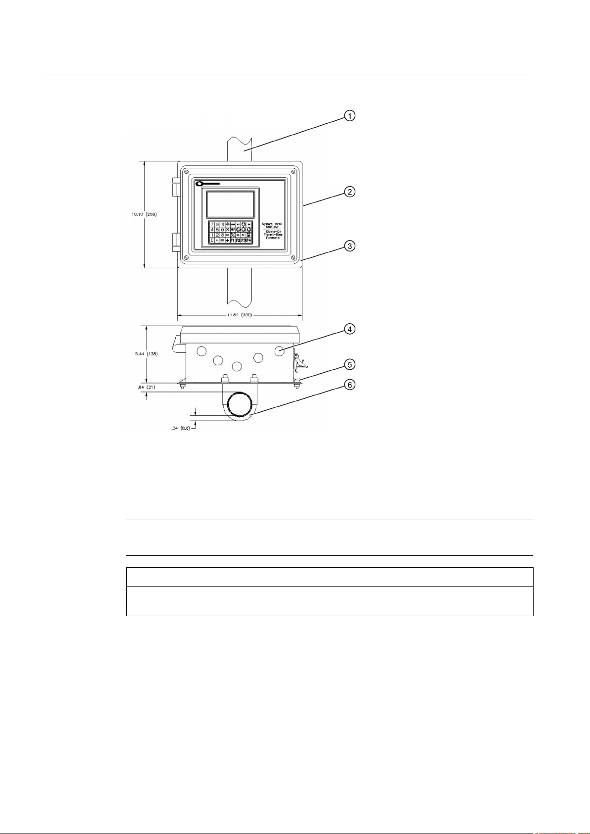
① Pipe ④ Cable Entry Ports
② Transmitter ⑤ Mounting Flange (also use for wall mounting)
③ Mounting Plate ⑥ U-Bolt Assembly for standard 2-inch pipe (6 cm / 2 in)
Figure 2-1 Pipe Mounting and Mounting Locations for Transmitter
Note
Use conduit fittings or cable glands on all cables.
CAUTION
Install weather tight seals at all unused holes using proper cable conduit and close additional
holes to IP65 standards.
12
FUT1010 IP65 NEMA 4X & IP66 NEMA 7 Liquid Quick Start
Operating Instructions, 6/2010, A5E02639182A Revision 02
2.3 Sensor Label Information
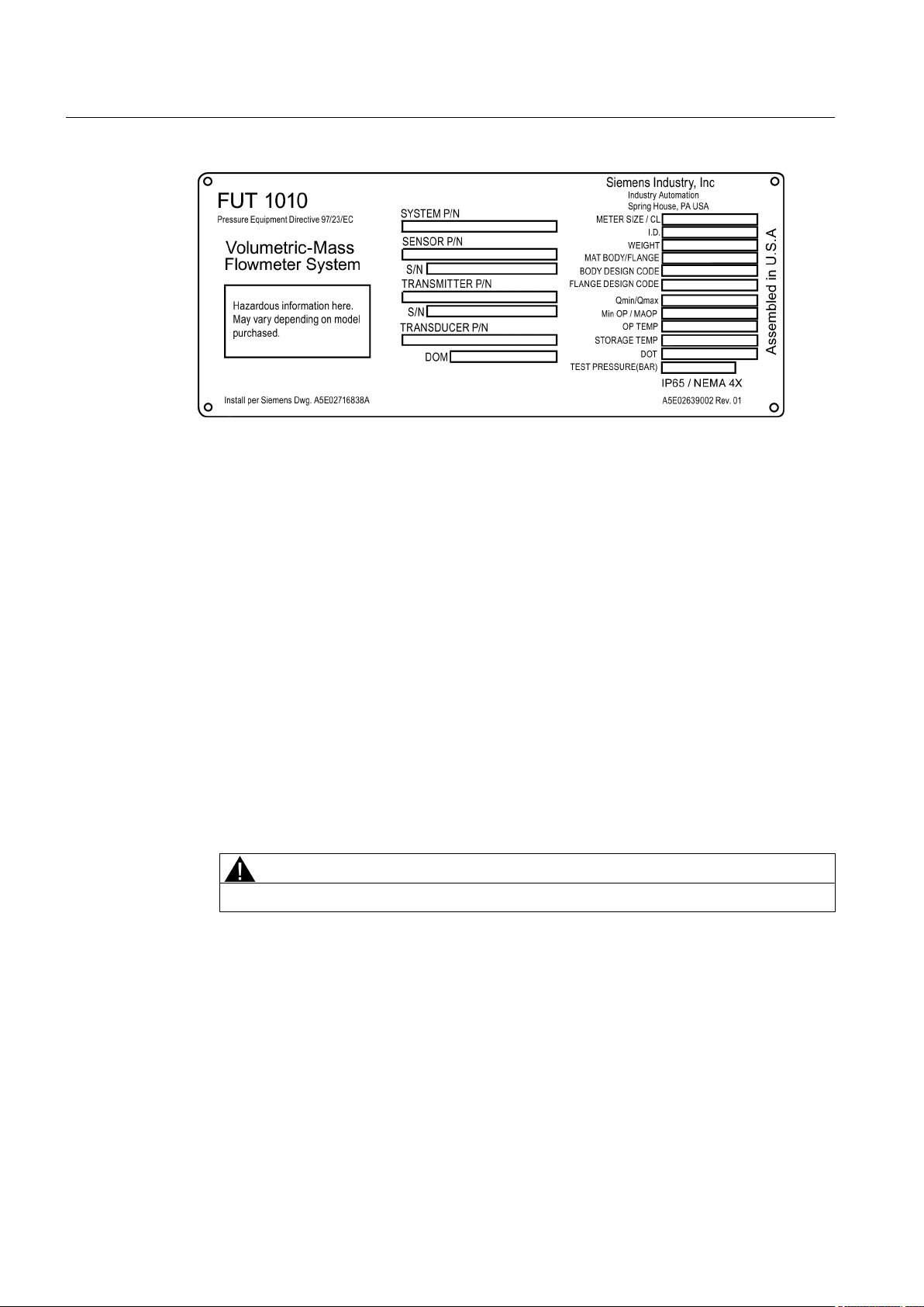
Sensor Label Markings
All Sensors are supplied with a metallic nameplate attached directly to the surface of the
Sensor. The nameplate displays information regarding the operating limits of the Sensor as
well as dimensional and other information required to insure the proper application and
operation of the flowmeter. The information included in the Sensor nameplate is listed below:
● SIEMENS (Manufacturer of this flowmeter)
● METER BODY MODEL and SERIAL # (Code contains Sensor material, size and flange
class)
● FLOWMETER P/N and SERIAL # (Indicates the specific transmitter electronics configured
for this Sensor)
● TRANSDUCER P/N (Indicates part number of the transducers installed in this Sensor)
● DOM (Date of Manufacture MM/DD/YY)
● METER SIZE / CL (Meter size with ANSI or DIN flange class rating)
Installing/mounting
2.3 Sensor Label Information
● I.D. (Internal Diameter of Sensor)
● WEIGHT (Weight of Sensor indicated in either Lbs or Kg)
● MAT BODY/FLANGE (Material of Sensor and flanges)
● BODY DESIGN CODE (Design code to which Sensor is fabricated)
● FLANGE DESIGN CODE (Design code to which flowmeter flanges are fabricated)
● Qmin / Qmax (Minimum and maximum actual flow that can be measured within AGA8
accuracy guidelines)
● Min OP (minimum operating pressure required for accurate flow measurement)
● MAOP (maximum allowable operating pressure of Sensor)
● OP TEMP (Operating temperature range of Sensor, including transducers)
● STORAGE TEMP (Recommended storage temperature of Sensor)
● HYDROSTATIC TEST PRESSURE (DOT MM/DD/YY)
WARNING
HOT SURFACE - External spool temperature can exceed 93°C (200°F).
WARNING
Exceeding rated pressure identified as MAOP may cause Sensor failure.
FUT1010 IP65 NEMA 4X & IP66 NEMA 7 Liquid Quick Start
Operating Instructions, 6/2010, A5E02639182A Revision 02
13
Installing/mounting
2.4 Sensor Installation Procedure
Figure 2-2 Sample Sensor Label
2.4 Sensor Installation Procedure
Pre-Installation Check List
All
Sensors are assembled with the final transducers and are mated to the selected transmitter
electronics prior to delivery. The transmitter is pre-programmed with the installation parameters
specific to this Sensor, therefore the installer should verify that the transmitter serial number
matches the transmitter serial number indicated on the Sensor nameplate.
Perform the following checklist before installing the Sensor into the line:
1. Verify that the line operating conditions (flow velocity, pressure, temperature range) and
line MAOP are within the limits specified for the flowmeter.
2. Verify that the transmitter electronics is paired with the serial number listed on the Sensor
nameplate.
3. Check the condition of any pressure taps or Thermowell ports that may be provided with
the Sensor. Install block valves, Thermowell, or plugs as necessary.
WARNING
User is responsible for ensuring that all Sensor ports are properly sealed.
14
FUT1010 IP65 NEMA 4X & IP66 NEMA 7 Liquid Quick Start
Operating Instructions, 6/2010, A5E02639182A Revision 02
Installing/mounting
2.4 Sensor Installation Procedure
4. User must verify that fluid is compatible with construction of Sensor material.
WARNING
It is the responsibility of the user to account for any potential misuse of gas equipment
confused with liquid equipment or visa versa.
WARNING
Materials of construction are chosen based on their chemical compatibility (or inertness)
for general purposes. For exposure to specific environments, check with chemical
compatibility charts before installing.
WARNING
Sensors have been designed to account for loads to internal pressures in accordance
with ASME codes. It is the responsibility of the user to access and account for other
externally applied loads due to earthquakes, pipe movement and other environmental
conditions.
5. It is the responsibility of the user to avoid excessive corrosion, erosion or chemical attack
due to the use of incompatible fluids or severe conditions.
Installation Procedure
Sensor is supplied with flanges suitable for handling. Lifting device should be within 10 degrees
of vertical of the axis of the lifting eye.
WARNING
During vertical installation of the Sensor use appropriate equipment to ensure safety.
WARNING
The user is responsible for the selection of bolting and gasket materials which will fall within
limits of the flange and its intended use and which are suitable for the service conditions.
the
WARNING
Never attempt to loosen, remove, or disassemble process connection or instrument housing
while contents are under pressure.
Each Sensor is labeled with a flow direction arrow indicating the direction of positive (POS)
FLOW. Although the flowmeter allows bi-directional flow, this arrow simply indicates the
direction
of positive flow so that the transducer cables can be installed without confusion. Install
the Sensor into the lines with careful attention to this flow direction arrow and also the rotational
orientation as described below.
WARNING
Remove all condensation from Sensor before installing into line.
FUT1010 IP65 NEMA 4X & IP66 NEMA 7 Liquid Quick Start
Operating Instructions, 6/2010, A5E02639182A Revision 02
15
Installing/mounting
2.4 Sensor Installation Procedure
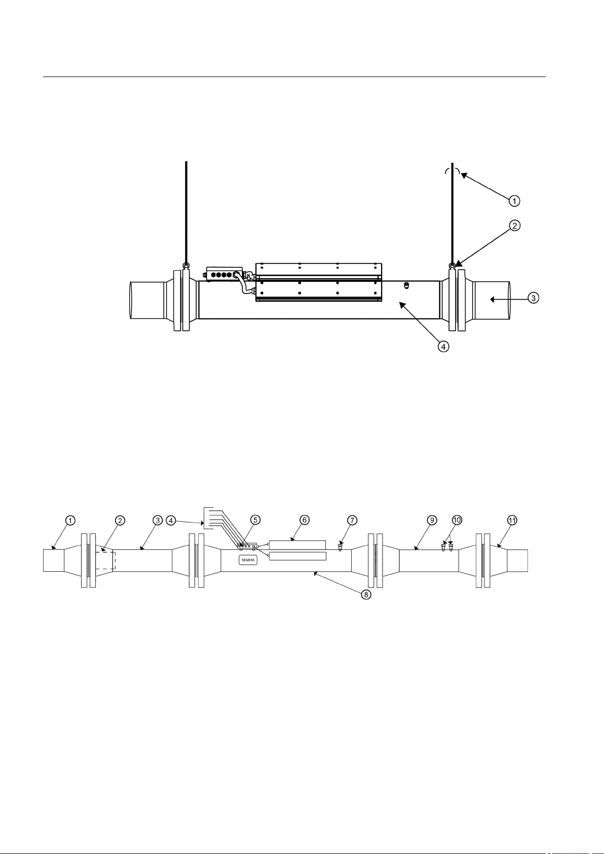
Installation of the Sensor should be installed with the lifting eyes at or near the top of the Sensor
(see figure below). Vertical installations have no restrictions since there are no cavities or
Sensor ports to collect condensate and debris.
① Lifting cable within 10° of vertical ③ Horizontal Alignment
② Lifting Eye ④ Sensor
Figure 2-3 Sensor Installation
Always
size and class of the Sensor flange. Flange Isolation kits (not supplied) should be utilized when
indicated by the facility.
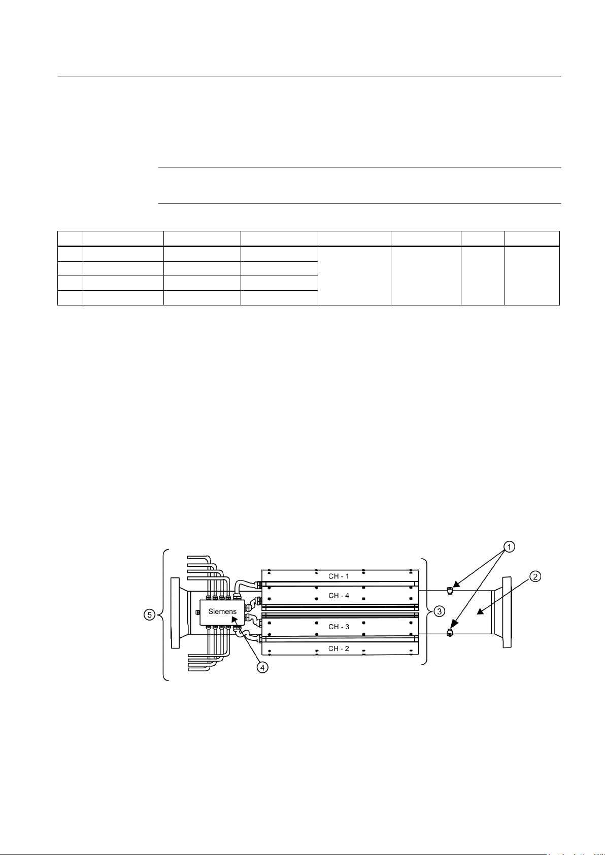
The following figure illustrates the hazardous location installation of the Sensor. It is shown
connected to the upstream and downstream pipes with the optional flow conditioner installed
and connected to the customer's pipe.
use flange bolts and nuts (not supplied unless requested) that are appropriate for the
① Customer's Pipe ⑥ Transducer Enclosure (2, 3 or 4 places. See Note 1)
② Flow Conditioner (Optional) ⑦ Line Taps (2) (See Note 3)
③ Upstream Pipe (Optional) ⑧ Sensor (See Note 4)
④ To Transmitter (See Note 1) ⑨ Downstream Pipe (Optional)
⑤ Junction Box (See Note 1) ⑩ Line Taps (2) (Refer to Note 3)
⑪ Customer's Pipe
Figure 2-4 Hazard Location Sensor Installation
16
FUT1010 IP65 NEMA 4X & IP66 NEMA 7 Liquid Quick Start
Operating Instructions, 6/2010, A5E02639182A Revision 02
Installing/mounting
2.4 Sensor Installation Procedure
Note
1
HazLoc qualified transducers type 7ME39501xxxx and 7ME39502xxxx are installed in the
enclosures
and prewired to the Junction Box. All connections to the transmitter are made in
the Junction Box, which also houses the Resistive Temperature Device (RTD).
Note
2
See table below for the appropriate drawing defining the circuit connection restrictions
dependent on transmitter type and hazardous area ratings.
Note
3
spool meter body has two line taps for end user temperature, pressure and other sensors.
The
Ensure that any devices used are appropriate for the area rating.
Note
4
Sensor Model numbers 7ME362... and 7ME363... can be used with any of the transmitter
types indicated in the Hazardous Area Ratings table below. The area ratings shown define
the permitted locations for sensor installation. Refer to the specific drawings for additional
restrictions of the transmitter location area rating.
Note
Not all transmitter models are offered with this configuration.
Table 2-1 Hazardous Area Ratings
Transmitter Area Rating (see Note 4)
Siemens Model No. Legacy Model No. ATEX Zone 0/1 ATEX Zone 2 FM/CSA Division
1 and 2
7ME3500... 1010N 1010-389 1010-391 1010-304
7ME3530... 1010MN, 1010N
7ME3600...
7ME3610...
7ME3532... 1010WX 1010-464 1010-443
7ME3533...
7ME3602...
7ME3603...
7ME3612...
7ME3613...
FUT1010 IP65 NEMA 4X & IP66 NEMA 7 Liquid Quick Start
Operating Instructions, 6/2010, A5E02639182A Revision 02
17

Installing/mounting
2.4 Sensor Installation Procedure
Transmitter Area Rating (see Note 4)
7ME3531... 1010X 1010-422 1010-423 1010-341
7ME3601...
7ME3611...
18
FUT1010 IP65 NEMA 4X & IP66 NEMA 7 Liquid Quick Start
Operating Instructions, 6/2010, A5E02639182A Revision 02
Connecting
3.1 Transmitter Wiring
3.1.1 Connecting Power
3
DANGER
Turn off main power before installing AC connections to the transmitter. Contact with exposed
wiring may lead to fire, electric shock, or serious personal injury.
1. Open the transmitter top cover.
2.
Unscrew the two power supply access cover fasteners and remove access cover.
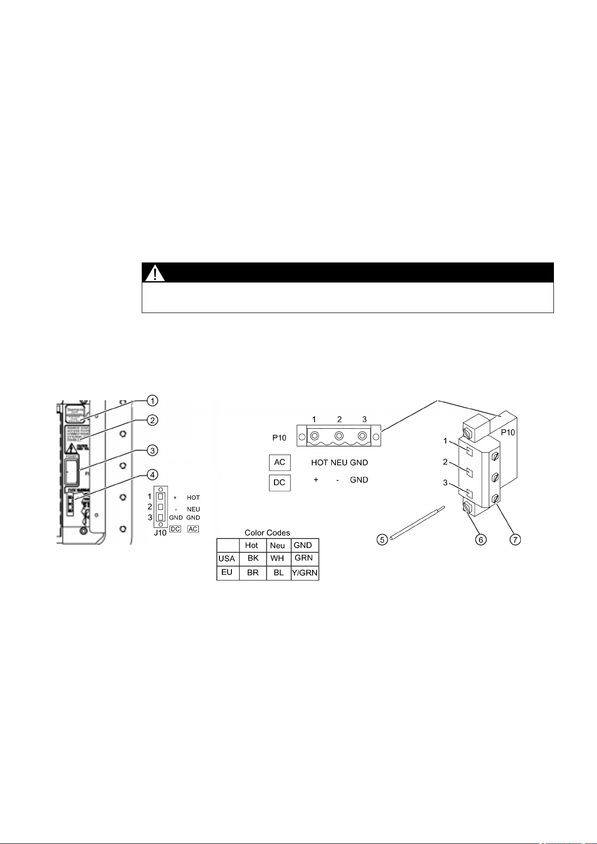
3. Locate power supply connector J10. Using a flat blade screwdriver, remove plug P10 from
connector J10. Set aside.
① Power Supply ⑤ Stripped Wire
② Power Supply Access Cover ⑥ Connector Mounting Screws
③ Fuse F1 ⑦ Wire Clamp Screws
④ Input Power Conn. J10
Figure 3-1 Input Power Plug (P10) Wiring
4. Pull
FUT1010 IP65 NEMA 4X & IP66 NEMA 7 Liquid Quick Start
Operating Instructions, 6/2010, A5E02639182A Revision 02
the desired length of input power wires through a cable gland and into transmitter case
before wiring connector.
19
Connecting
3.1 Transmitter Wiring
5. As
6. Insert wires into wire entry holes and secure by tightening wire clamp screws (see figure
7. Plug input power plug P10 into connector J10 and secure using two captive connector
8.
per local electric codes, wire input power connector P10 for AC or DC power depending
on power supply provided.
Note
Dress cables and make sure cable length is not excessive as to impede proper
replacement of access cover.
above).
Note
Power Supply connector wires should be stripped AWG 12 - 18 stranded wire or solid
conductors.
mounting screws.
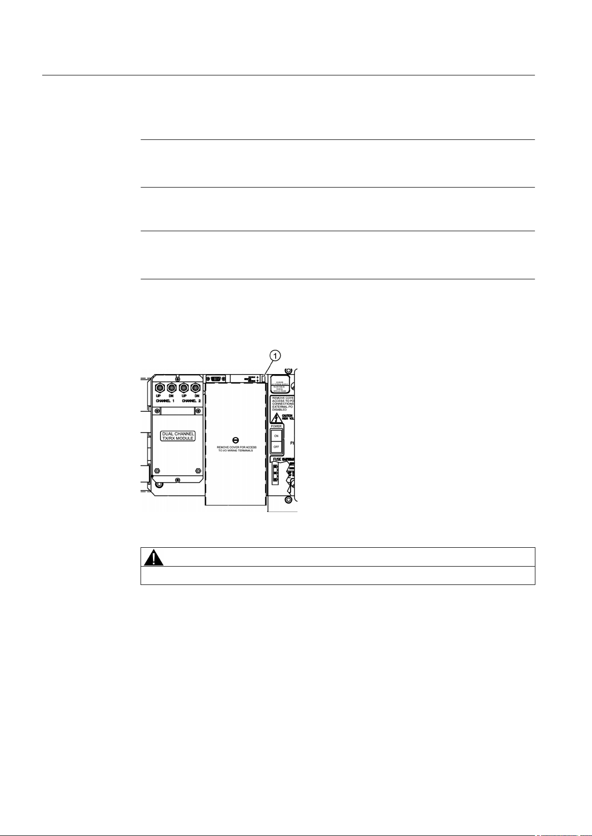
Replace access cover. Make sure Keypad Enable switch is in the "Enable" position (see
below).
20
① Enable Switch
9. Connect the power cables to the appropriate power source (100-250 VAC @ 50/60 Hz or
CAUTION
Improper power connections will damage power supply.
9-36 Vdc). Close top cover.
FUT1010 IP65 NEMA 4X & IP66 NEMA 7 Liquid Quick Start
Operating Instructions, 6/2010, A5E02639182A Revision 02
3.1.2 Connecting Sensor Cables to Transmitter
1.
Open the transmitter top cover. Using a flat blade screwdriver, remove the Cable Strain
Relief bracket.
Connecting
3.1 Transmitter Wiring
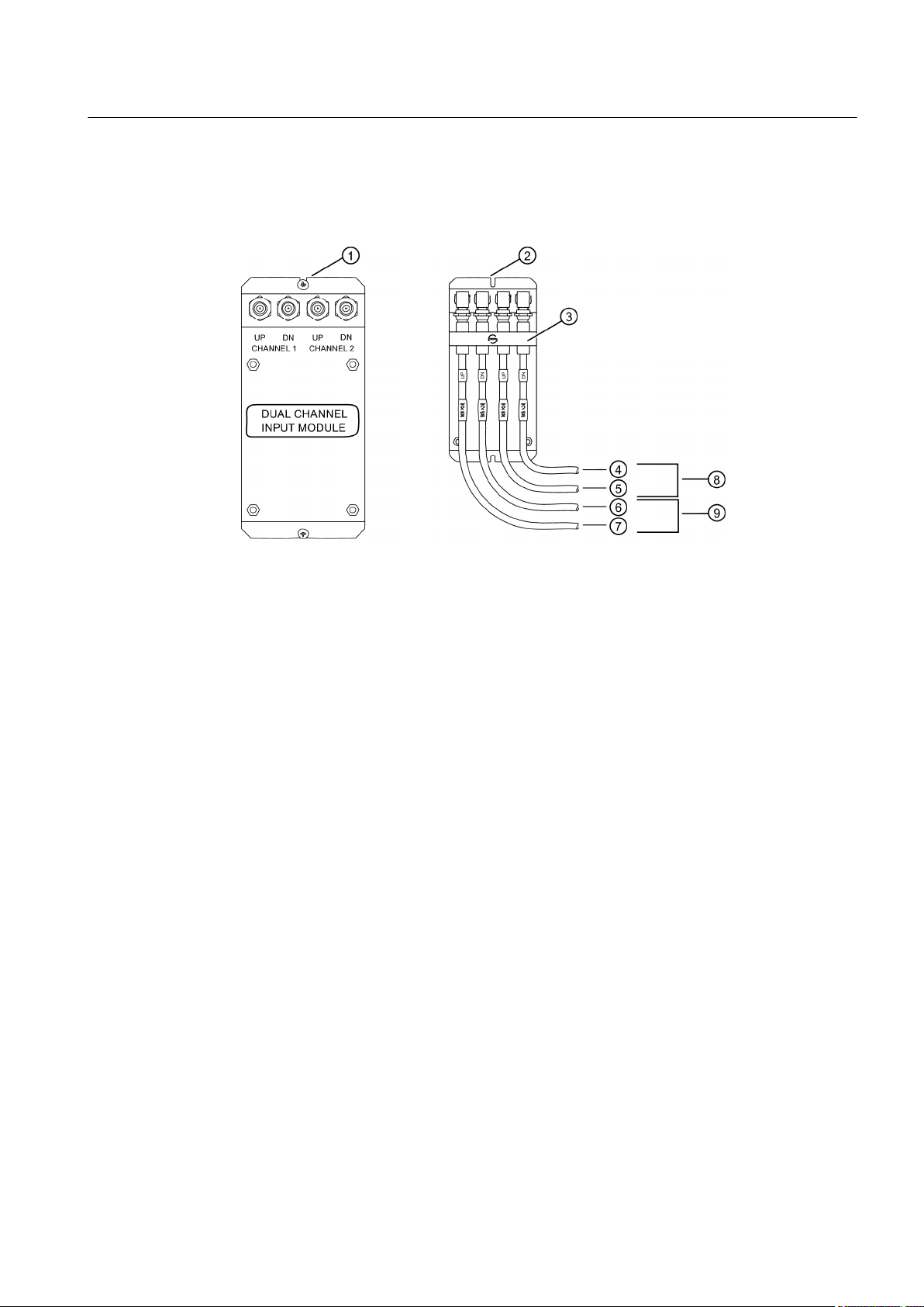
① Transmitter Input Module ⑤ To CH-2 UP
② Transducer Cables Connected to
Transmitter
⑥ To CH-1 DN
③ Cable Strain Relief Bracket ⑦ To CH-1 UP
④ To CH-2 DN ⑧ Channel 2 to Junction Box
⑨ Channel 1 to Junction Box
Figure 3-2 Sensor Cable Connections
2. Observing
cable glands.
3. Attach the Sensor cables to Channel 1 and Channel 2 UP and DN Input Module Fconnectors. Repeat for additional paths as necessary.
4. Replace the Cable Strain Relief bracket. Close transmitter top cover.
5. If not installing a Temperature Sensor, proceed to Sensor Wiring.
the upstream to downstream orientation, pull Sensor cables through transmitter
FUT1010 IP65 NEMA 4X & IP66 NEMA 7 Liquid Quick Start
Operating Instructions, 6/2010, A5E02639182A Revision 02
21

Connecting
3.1 Transmitter Wiring
3.1.3 Wiring Temperature Sensor to Transmitter
Wiring Temperature Sensor Board to Transmitter
DANGER
Set transmitter and instrumentation power to OFF when inserting or removing the Analog
Input Module, or when making connections to TB1, TB2, TB3 and TB4.
1. Disconnect power to the transmitter.
2. Open transmitter top cover by releasing the cover latch.
3. Loosen the captive screw securing the Access Cover and remove Access Cover.
4. Using a flat-blade screwdriver, remove four screws securing the I/O Module board. Remove
board and set it aside.
22
FUT1010 IP65 NEMA 4X & IP66 NEMA 7 Liquid Quick Start
Operating Instructions, 6/2010, A5E02639182A Revision 02
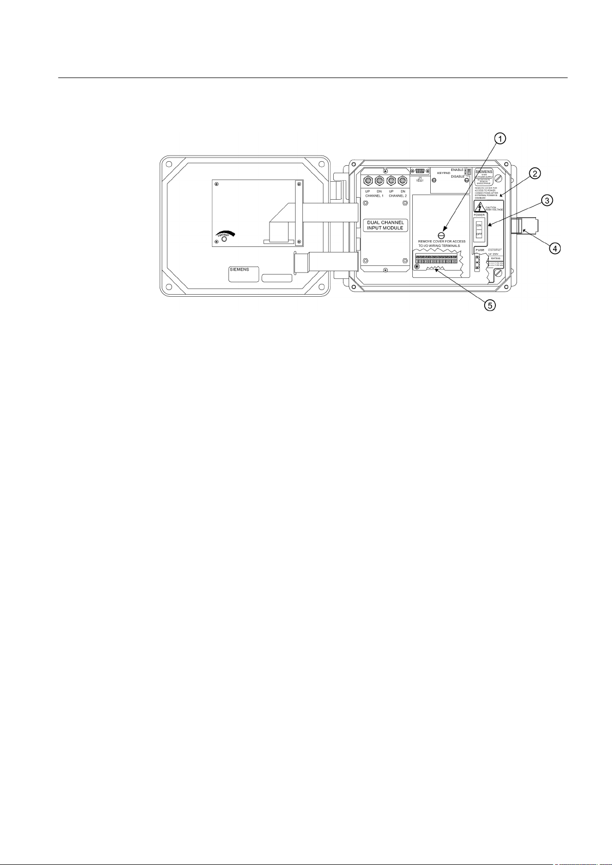
3.1 Transmitter Wiring
① Access Cover Screw ④ Latch
② Flowmeter ⑤ Access to Analog Input Module
③ Power Switch
Connecting
Figure 3-3 Analog Input Module Access
FUT1010 IP65 NEMA 4X & IP66 NEMA 7 Liquid Quick Start
Operating Instructions, 6/2010, A5E02639182A Revision 02
23
Connecting
3.1 Transmitter Wiring
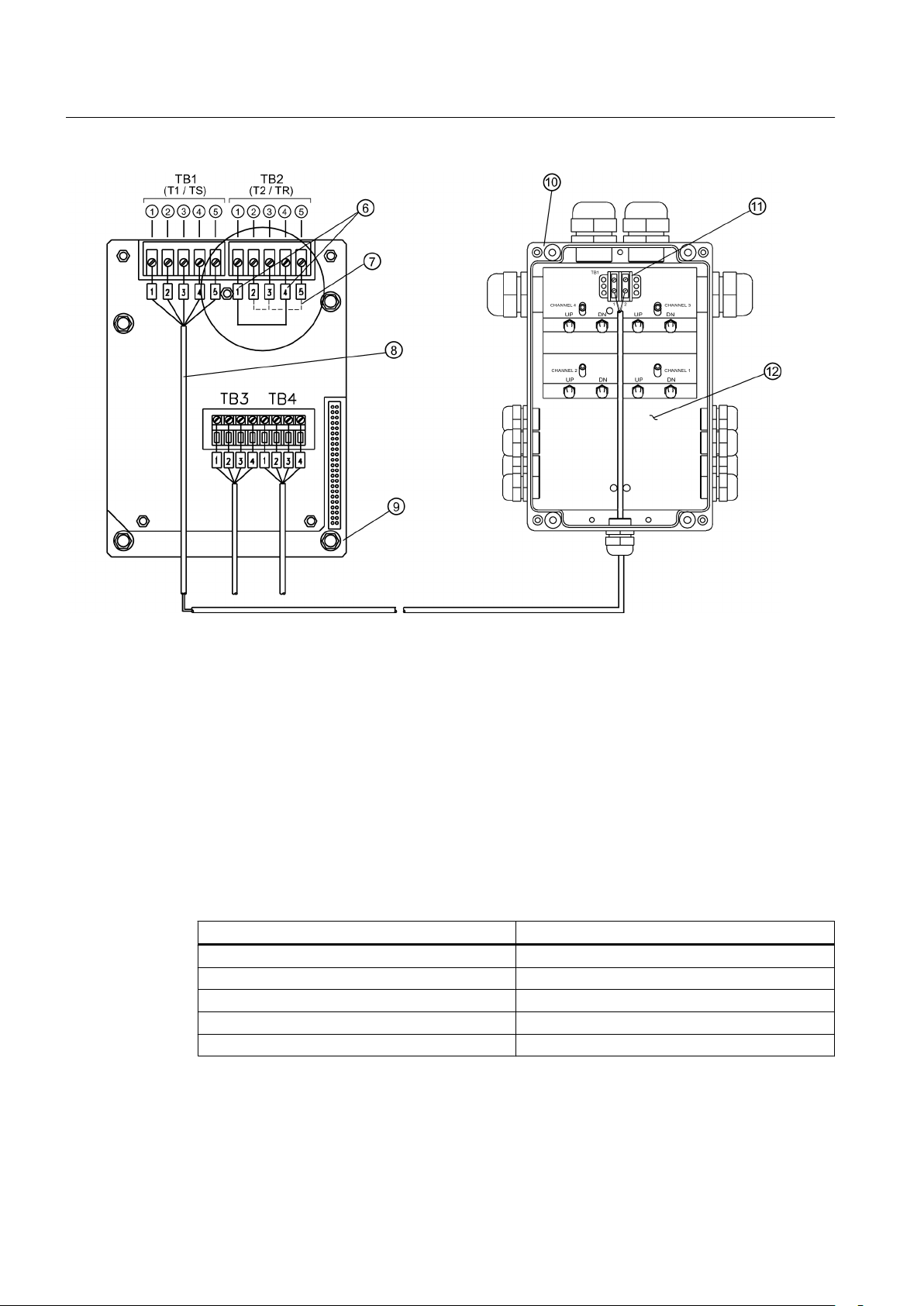
① Black ⑦ Ground Terminals 2 and 3 to Terminal 5
② Orange ⑧ 1012EC Series Cable
③ Brown ⑨ Module 7ME39400SA00
④ Red ⑩ Sensor Body Junction Box
⑤ Blue ⑪ Temperature Sensor Terminal Board TB1
⑥ Short Terminals 1 and 4 ⑫ Junction Box shown with cover removed
Figure 3-4 Temperature Sensor to Junction Box Wiring
Wiring Temperature Sensor Board
Using a flat-blade screwdriver, loosen Terminal Block TB1 and TB2 screws.
1.
Wire the RTD 1012EC temperature cable as shown in the table below:
2.
1012EC Series Cable Terminal TB1
Wire #1 (Black) To TB1--1
Wire #2 (Orange) To TB1--2
Wire #3 (Brown) To TB1--3
Wire #4 (Red) To TB1--4
Wire #5 GND/SHLD (Blue) To TB1--5
3. Complete the temperature sensor current loop by shorting together terminals 1 and 4 of
the unused TB2 temperature sensor terminal block.
24
4. Ground the voltage sensing leads (terminals 2 and 3 of TB2) by connecting them both to
terminal 5.
FUT1010 IP65 NEMA 4X & IP66 NEMA 7 Liquid Quick Start
Operating Instructions, 6/2010, A5E02639182A Revision 02
Connecting
3.2 Sensor Wiring
5. Tighten all TB1 and TB2 terminal block screws.
6. Replace I/O Board and secure with four screws paying careful attention to pin alignment.
7. Replace Access Cover, tighten captive screw and close transmitter case.
Note
TB3 and TB4 are also active analog inputs. See wiring table below.
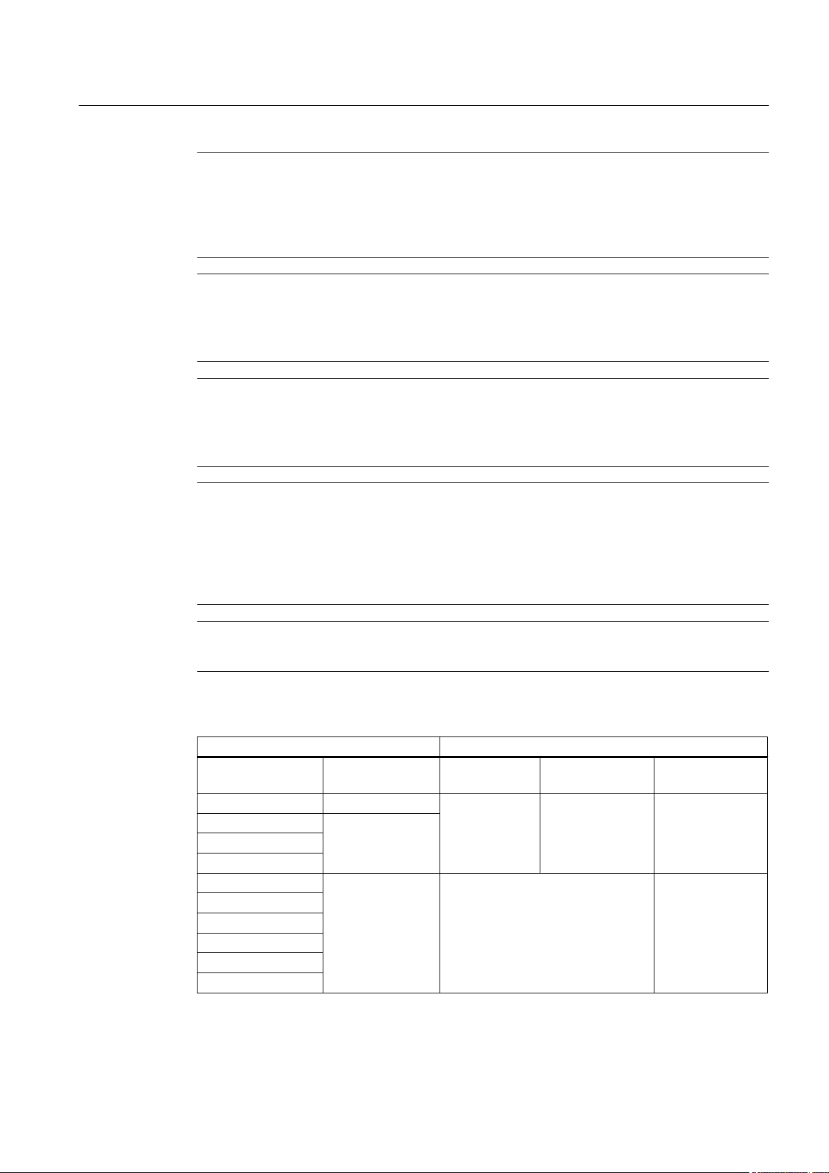
Table 3-1 TB3 and TB4 Wiring
Pin TB3 Function TB4 Function Use Description Behaviour Load Wiring
1 AUX. 1 IN AUX. 3 IN Iin1 Input Analog current
2 AUX. 1 COM AUX. 3 COM Iin1 Common
3 AUX. 2 IN AUX. 4 IN Iin2 Input
4 AUX. 2 COM AUX. 4 COM Iin2 Common
input
referenced to
meter ground.
4 to 20mA 200Ω 1000 ft.
Max w/o
factory
approval
Notes on Analog Input Modules
Dual Path Models
● All models use T1 to report temperature.
● The Analog Input of temperature takes priority over the built-in RTD (Resistive Thermal
Device) measurement of temperature when provided.
3.2 Sensor Wiring
3.2.1 Connecting Sensor Cables to Sensor
① Line Taps (1/4" and 3/4") ④ Junction Box
② Sensor Pipe Section ⑤ Upstream and Downstream I/O Cables
③ Sensor Enclosures
Figure 3-5 Sensor Overview
FUT1010 IP65 NEMA 4X & IP66 NEMA 7 Liquid Quick Start
Operating Instructions, 6/2010, A5E02639182A Revision 02
25
Connecting
3.2 Sensor Wiring
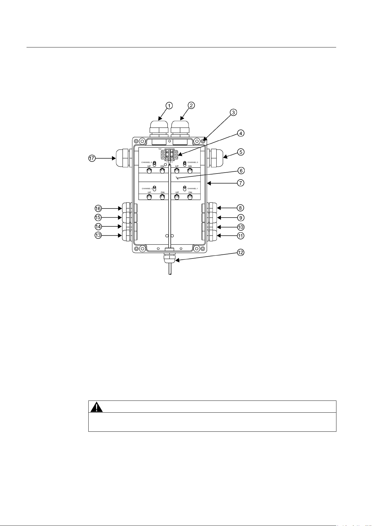
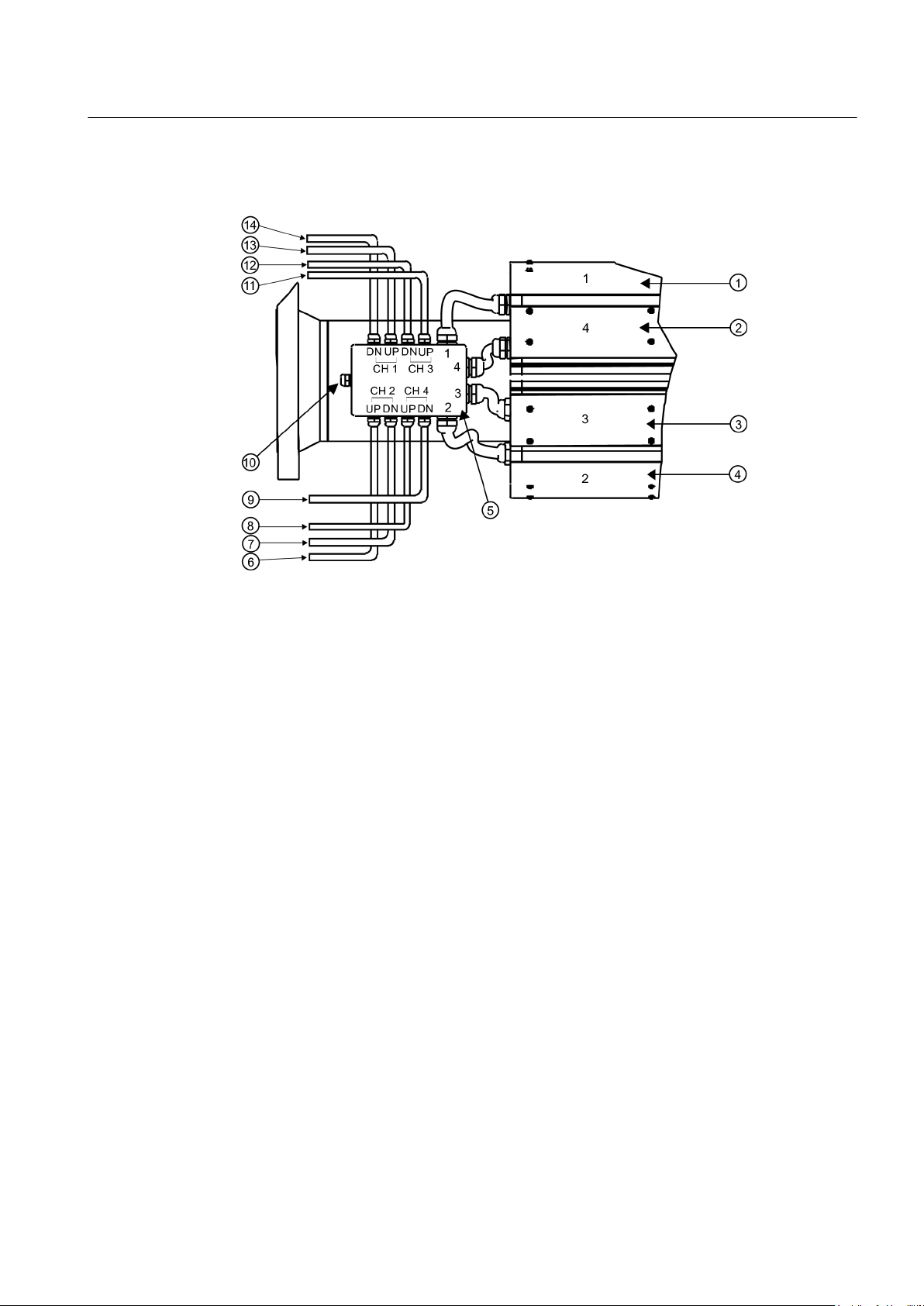
1. Remove four (4) #10 bolts securing Junction Box top cover. Remove cover and set aside
bolts.
① CH 4-Sensor to Junction Box Gland ⑨ CH 4 - UP to Transmitter
② CH 3-Sensor to Junction Box Gland ⑩ CH 2 - DN to Transmitter
③ Top Cover #10 bolts (4) ⑪ CH 2 - UP to Transmitter
④ Temperature Sensor Terminal Board TB1 ⑫ Temperature Sensor Gland
⑤ CH 2-Sensor to Junction Box Gland ⑬ CH 1 - DN to Transmitter
⑥ Transducer Channel F-Connectors ⑭ CH 1 - UP to Transmitter
⑦ Junction Box without top cover ⑮ CH 3 - DN to Transmitter
⑧ CH4 - DN to Transmitter ⑯ CH 3 UP to Transmitter
⑰ CH 1-Sensor to Junction Box Gland
Figure 3-6 Sensor Cable Installation
2. Observing the upstream to downstream orientation, pull Channel-1 and Channel-2 UP and
DN Sensor cables into the corresponding CH-1 and CH-2 Junction Box glands.
CAUTION
When connecting sensor cables inside Junction Box cable bend radius should not exceed
bend tighter than 8 cm (3 in.) or damage to cables may result.
26
FUT1010 IP65 NEMA 4X & IP66 NEMA 7 Liquid Quick Start
Operating Instructions, 6/2010, A5E02639182A Revision 02
Connecting
3.2 Sensor Wiring
3. Secure
finger tight.
cables to CH-1 and CH-2 UP and DN F-connectors making sure the connection is
① Channel 1 Transducers ⑧ CH 4 UP to Transmitter
② Channel 4 Transducers ⑨ CH 4 DN to Transmitter
③ Channel 3 Transducers ⑩ Temperature Sensor Cable Gland
④ Channel 2 Transducers ⑪ CH 3 UP to Transmitter
⑤ Junction Box ⑫ CH 3 DN to Transmitter
⑥ CH 2 UP to Transmitter ⑬ CH 1 DN to Transmitter
⑦ CH 2 DN to Transmitter ⑭ CH 1 UP to Transmitter
Figure 3-7 Sensor Interconnection Diagram
Repeat for additional paths, if necessary.
4.
FUT1010 IP65 NEMA 4X & IP66 NEMA 7 Liquid Quick Start
Operating Instructions, 6/2010, A5E02639182A Revision 02
27
Connecting
3.2 Sensor Wiring
3.2.2 Wiring Temperature Cable to Sensor
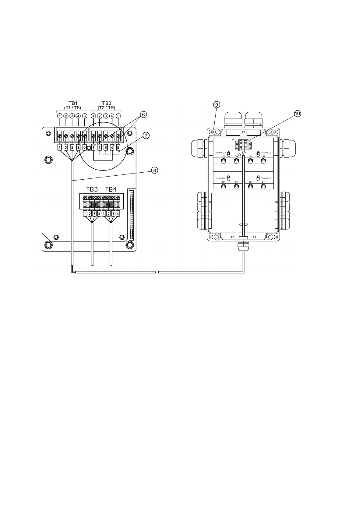
1. Locate Temperature Sensor terminal block TB1 connection screws.
2.
Insert Temperature Sensor cable from transmitter into Junction Box gland.
① Black ⑥ Short Terminals 1 and 4
② Orange ⑦ Ground Terminals 2 and 3 to Terminal 5
③ Brown ⑧ 1012EC Series Cable
④ Red ⑨ Junction Box with cover removed
⑤ Blue ⑩ Temperature Sensor Connections: TB1-1 Black/
Orange and TB1-2-Brown/Red. Tie off Blue
Figure 3-8 Temperature Sensor Board to Junction Box Wiring
3. Connect
● Insert Black and Orange wires into lug (supplied), crimp lug and connect lug to TB1-1.
● Insert Brown and Red wires into lug (supplied), crimp lug and connect lug to TB1-2.
● Tie off Blue wire.
● Make sure all terminal block lug connections are hand-tight.
4. Replace Junction Box top cover.
5. Reinstall and hand-tighten four (4) Junction Box securing bolts. Using a torque wrench,
torque each bolt to 6.8 to 8.1 Nm (5 to 6 ft-lbs).
Temperature
Sensor PCB wires to Junction Box Sensor terminal board as follows:
28
FUT1010 IP65 NEMA 4X & IP66 NEMA 7 Liquid Quick Start
Operating Instructions, 6/2010, A5E02639182A Revision 02
 Loading...