

Ultrasonic flowmeters
SITRANS FUP1010 IP67 7ME3510 Portable Flowmeter
Operating Instructions - March 2012

SITRANS F
Answers for industry.
SIEMENS
SIEMENS
SITRANS F
Ultrasonic Flowmeters FUP1010 IP67 Portable
Operating Instructions
| Introduction | 1 |
|---|---|
| Safety notes | 2 |
| Description | 3 |
| Installing/mounting | 4 |
| Connecting | 5 |
| Commissioning | 6 |
| Functions | 7 |
| Alarm, error, and system messages | 8 |
| Maintenance and service | 9 |
| Troubleshooting | 10 |
| Technical data | 11 |
| Appendix | Α |
| Appendix | В |

Legal information
Warning notice system
This manual contains notices you have to observe in order to ensure your personal safety, as well as to prevent damage to property. The notices referring to your personal safety are highlighted in the manual by a safety alert symbol, notices referring only to property damage have no safety alert symbol. These notices shown below are graded according to the degree of danger.
indicates that death or severe personal injury will result if proper precautions are not taken.
indicates that death or severe personal injury may result if proper precautions are not taken.
with a safety alert symbol, indicates that minor personal injury can result if proper precautions are not taken.
CAUTION
without a safety alert symbol, indicates that property damage can result if proper precautions are not taken.
NOTICE
indicates that an unintended result or situation can occur if the relevant information is not taken into account
If more than one degree of danger is present, the warning notice representing the highest degree of danger will be used. A notice warning of injury to persons with a safety alert symbol may also include a warning relating to property damage.
Qualified Personnel
The product/system described in this documentation may be operated only by personnel qualified for the specific task in accordance with the relevant documentation, in particular its warning notices and safety instructions. Qualified personnel are those who, based on their training and experience, are capable of identifying risks and avoiding potential hazards when working with these products/systems.
Proper use of Siemens products
Note the following:
Siemens products may only be used for the applications described in the catalog and in the relevant technical documentation. If products and components from other manufacturers are used, these must be recommended or approved by Siemens. Proper transport, storage, installation, assembly, commissioning, operation and maintenance are required to ensure that the products operate safely and without any problems. The permissible ambient conditions must be complied with. The information in the relevant documentation must be observed.
Trademarks
All names identified by ® are registered trademarks of Siemens AG. The remaining trademarks in this publication may be trademarks whose use by third parties for their own purposes could violate the rights of the owner.
Disclaimer of Liability
We have reviewed the contents of this publication to ensure consistency with the hardware and software described. Since variance cannot be precluded entirely, we cannot guarantee full consistency. However, the information in this publication is reviewed regularly and any necessary corrections are included in subsequent editions.
Siemens AG Industry Sector Postfach 48 48 90026 NÜRNBERG GERMANY
Order number: A5E02951522 © 03/2012 Technical data subject to change
Copyright © Siemens AG 2012. All rights reserved
Table of contents
| 1 | Introdu | uction | 9 |
|---|---|---|---|
| 1.1 | Preface | 9 | |
| 1.2 | Items supplied | 9 | |
| 1.3 | History | 9 | |
| 1.4 | Further Information | 10 | |
| 2 | Safety | notes | 11 |
| 2.1 | Laws and directives | 11 | |
| 2.2 | Lithium batteries | 12 | |
| 2.3 | Certificates | 12 | |
| 3 | Descri | ption | 13 |
| 3.1 | FUP1010 features | 13 | |
| 3.2 | Applications | 14 | |
| 3.3 | Theory of Operation | 15 | |
| 4 | Installi | ing/mounting | |
| 4.1 | Installation safety precautions | 21 | |
| 4.2 | Use according to specifications | 21 | |
| 4.3 | Application Guidelines | ||
| 4.4 | AC Battery Charger | ||
| 5 | Conne | ecting | |
|
5.1
5.1.1 5.1.2 |
Transmitter Wiring
Forming the Internal Battery Connecting AC Power Adapter/Charger |
||
|
5.2
5.2.1 5.2.2 5.2.3 5.2.4 5.2.5 5.2.6 5.2.7 |
Sensor Wiring
Preliminary Installation Procedures Sensor Identification and Selection Navigating the Menu Setting the Parameters Reflect Mount Direct Mount 1012T Mounting Tracks |
||
| 5.3 | Zero Flow Adjust Menu | 61 | |
| 6 | Comm | lissioning | |
| 6.1 | General requirements | ||
| 6.2 | Commissioning | 67 |
| 6.3 | Empty Pipe Set | ||||
|---|---|---|---|---|---|
| 6.4 | Installation Menus | 72 | |||
| 7 | Functio | ons | 77 | ||
| 7.1 | Selecting Flow Units | ||||
| 7.2 | Span Data | ||||
| 7.3 | Logger Control | ||||
| 7.4 | Operation Adjust Menu Settings | ||||
| 7.5 | Setting Relays | ||||
| 7.6 | Memory Control | ||||
| 7.7 | Analog Out Setup | ||||
| 7.8 | Analog Input Setup | ||||
| 7.9 | Analog Output Trim | ||||
| 7.10 | RTD Calibration | ||||
| 7.11 | Reflexor | ||||
| 8 | Alarm, | error, and system messages | 115 | ||
| 8.1 | Alarm Letter Codes | 115 | |||
| 9 | Maintenance and service | ||||
| 9.1 | Maintenance | 117 | |||
| 9.2 | Technical support | 117 | |||
| 9.3 | Replacing the battery | ||||
| 9.4 | Battery disposal | 121 | |||
| 9.5 | Disposal | ||||
| 9.6 | Return procedures | ||||
| 10 | Trouble | eshooting | |||
| 10.1 | Troubleshooting | ||||
| 10.2 | F4 Reset Procedure | ||||
| 10.3 | Test Facilities Graph Screen | ||||
| 10.4 | Site Setup Data | ||||
| 11 | Techni | ical data | |||
| 11.1 | Technical Data | ||||
| Α | Appen | dix | |||
| A.1 | Ordering | 143 | |||
| A.2 | I/O Connections and Wiring | 143 | |||
| A.3 | Site Setup For SITRANS F | 145 | |||
| A.4 | Flowrate Calibration and Calibration Tables | ||||
| В | Appendix | ٢ | 155 |
|---|---|---|---|
| B.1 | Installation/Outline Drawings | 155 | |
| Glossary | 157 | ||
| Index | 163 |
Tables
| Table 4- 1 | Power Cord Codes | 24 |
|---|---|---|
| Table 5- 1 | Keypad Function Chart | 35 |
| Table 5- 2 | Pipe Configuration Option List Definitions | |
| Table 7- 1 | Totalizer Modes | 78 |
| Table 7- 2 |
Totalizer Controls (the "n" in
|
80 |
| Table 7- 3 | Logger Control Menu Option List | 83 |
| Table 7-4 | Relay Option List | 89 |
| Table 7- 5 | Memory Control Menu | 91 |
| Table 7- 6 | Analog Outputs | 92 |
| Table 7- 7 | Analog Out Setup Data Categories | 92 |
| Table 7-8 | Analog Out Trim Menu Structure | 97 |
| Table 7- 9 | RTD Calibrate Menu Structure | 101 |
| Table 7- 10 | Inline Metal and Plastic Pipe Cable Connections | 105 |
| Table 7- 11 | Cursor Definitions | 110 |
| Table 7- 12 | Diagnostic Data | 112 |
| Table 8- 1 | Alarm Codes and Descriptions | 115 |
| Table 10- 1 | Troubleshooting Tips | 123 |
| Table 10- 2 | Description of Graph Screen Text Display Parameters | 134 |
| Table 10- 3 | Hot Key Summary | 135 |
| Table 10- 4 | Site Setup Menu Items | 136 |
| Table 11- 1 | Performance Specifications | 141 |
| Table A- 1 | Part Numbers and Connection Data | 143 |
| Table A- 2 | 2 Channel/2 Path Input/Output Terminal Block Wiring | 144 |
Figures
| Figure 3-1 | Weatherproof Case-shown open | 13 |
|---|---|---|
| Figure 4-1 | Power Adapter/Battery Charger | 23 |
| Figure 5-1 | Power Adapter/AC-Charger for Dual Channel Flow Meter | 27 |
| Figure 5-2 | Reflect Mount (Pipe shown from above in 12 o'clock position) | 28 |
|---|---|---|
| Figure 5-3 | Direct Mount (Pipe shown from above in 12 o'clock position) | 29 |
| Figure 5-4 | Sensor Alignment (Horizontal Plane) | 30 |
| Figure 5-5 | Pipe Surface Preparation | 31 |
| Figure 5-6 | Universal Sensor Label | 32 |
| Figure 5-7 | Hi Precision Sensor Label | 33 |
| Figure 5-8 | KeyPad | 34 |
| Figure 5-9 | Typical Installation Menu Screen | 35 |
| Figure 5-10 | Reflect Mount with EZ-Clamp and Spacer Bar | 41 |
| Figure 5-11 | Sensor Mounting with E-Z Clamp and Spacer Bar | 43 |
| Figure 5-12 | E-Z Clamp S-Hook | 43 |
| Figure 5-13 | Sensor | 43 |
| Figure 5-14 | Connecting Sensors to Flow Meter | 44 |
| Figure 5-15 | Mylar Spacing Guide | 45 |
| Figure 5-16 | EZ Clamping Sensor to Pipe | 46 |
| Figure 5-17 | E-Z Clamp S-Hook | 46 |
| Figure 5-18 | Sensor | 46 |
| Figure 5-19 | Wrapping the Mylar Spacing Guide around the pipe (End View) | 48 |
| Figure 5-20 | Finding the Halfway Distance | 49 |
| Figure 5-21 | Aligning the Sensors for Direct Mode (End View) | 49 |
| Figure 5-22 | Connecting Sensors to Flow Meter | 50 |
| Figure 5-23 | Reflect Mount with Model 1012TP Mounting Track (Side View) | 52 |
| Figure 5-24 | Reflect Mode Chain Loop (Front View) | 53 |
| Figure 5-25 | Direct Mount 180° opposed with Mounting Tracks | 55 |
| Figure 5-26 | Direct Mount Roller Chain | 57 |
| Figure 5-27 | Wrapping the Mylar Spacing Guide around pipe (End View) | 58 |
| Figure 5-28 | Finding the Halfway Distance | 58 |
| Figure 5-29 | Track Rail Alignment | 59 |
| Figure 5-30 | REF and Number Index Pin Locations | 60 |
| Figure 7-1 | Sensor Mounting Examples | 104 |
| Figure 7-2 | Adjacent Sensor Mounting | 105 |
| Figure 7-3 | In-Line Sensor Mounting | 106 |
| Figure 7-4 | Spectra Graph Display Screen | 109 |
| Figure 9-1 | Faceplate Removal | 119 |
| Figure 9-2 | Battery Cover Removal | 120 |
| Figure 9-3 | Battery Removal/Replacement | 121 |
| Figure 10-1 | Test Facilities Graph Screen | .127 |
|---|---|---|
| Figure 10-2 | Setting Digital Damping Factor | .130 |
| Figure 10-3 | Setting the MinDamp Factor | .131 |
| Figure 10-4 | Envelope Threshold Adjustment | .133 |
Table of contents
Introduction
1.1
Preface
These instructions contain all the information you need for using the device.
The instructions are aimed at persons mechanically installing the device, connecting it electronically, configuring the parameters and commissioning it as well as service and maintenance engineers.
Note
It is the responsibility of the customer that the instructions and directions provided in the manual are read, understood and followed by the relevant personnel before installing the device.
1.2 Items supplied
- SITRANS F Transmitter
- SITRANS F literature CD
- For additional items refer to your packing slip.
Inspection
- 1. Check for mechanical damage due to possible improper handling during shipment. All claims for damage are to be made promptly to the shipper.
- 2. Make sure the scope of delivery, and the information on the type plate corresponds to the ordering information.
1.3 History
The contents of these instructions are regularly reviewed and corrections are included in subsequent editions. We welcome all suggestions for improvement.
The following table shows the most important changes in the documentation compared to each previous edition.
FUP1010 IP67 Portable
1.4 Further Information
| Edition | Remarks |
|---|---|
| 2/2010 | First Edition |
|
3/2012 Second Edition of Operating Instructions for the SITRANS FUP1010 IP67 portable f
meter. This document replaces all previous instructions for use. The most important changes are as follows: |
|
| The most important changes are as follows: | |
| Updated "Forming the Internal Battery" procedure | |
| Removed all references to External Battery Pack and Charger | |
| Added Reflexor operating mode chapter | |
| Updated Sensor label and sensor selection procedures | |
| Added 2mA drop fault indication note | |
| Added DIN pipe size table 2448 reference note | |
| Added Empty Pipe Set procedure | |
| Updated Troubleshooting Table | |
1.4 Further Information
The contents of these Operating Instructions shall not become part of or modify any prior or existing agreement, commitment or legal relationship. All obligations on the part of Siemens AG are contained in the respective sales contract which also contains the complete and solely applicable warranty conditions. Any statements contained herein do not create new warranties or modify the existing warranty.
Product information on the Internet
The Operating Instructions are available on the CD-ROM shipped with the device, and on the Internet on the Siemens homepage, where further information on the range of SITRANS F flowmeters may also be found:
Product information on the internet (http://www.siemens.com/flow)
Worldwide contact person
If you need more information or have particular problems not covered sufficiently by the operating instructions, please get in touch with your contact person. You can find contact information for your local contact person on the Internet:
Local contact person (http://www.automation.siemens.com/partner)
Safety notes
Correct, reliable operation of the product requires proper transport, storage, positioning and assembly as well as careful operation and maintenance. Only qualified personnel should install or operate this instrument.
Note
Alterations to the product, including opening or improper repairs of the product, are not permitted.
If this requirement is not observed, the CE mark and the manufacturer's warranty will expire.
2.1 Laws and directives
General requirements
Installation of the equipment must comply with national regulations. For example, the National Electrical Codes.
Instrument safety standards
The device has been tested at the factory, based on the safety requirements. In order to maintain this condition over the expected life of the device the requirements described in these Operating Instructions must be observed.
CAUTION
Aaterial compatibilit
Siemens can provide assistance with the selection of sensor parts. However, the full responsibility for the selection rests with the customer and Siemens can take no responsibility for any failure due to material incompatibility.
2.2 Lithium batteries
CE marked equipment
The CE-mark symbolizes the compliance of the device with the following Directives:
- EMC-Directive 2004/108/EC
- Low voltage Directive 2006/95/EC
- ATEX Directive 94/9/EC
2.2 Lithium batteries
Lithium batteries are primary power sources with high energy content designed to represent the highest possible degree of safety.
Potential hazard
Lithium batteries may present a potential hazard if they are abused electrically or mechanically. This is in most circumstances associated with the generation of excessive heat where internal pressure may cause the cell to rupture.
Thus the following basic precautions should be observed when handling and using lithium batteries:
- Do not short-circuit, recharge or connect with false polarity.
- Do not expose to temperature beyond the specified temperature range or incinerate the battery.
- Do not crush, puncture or open cells or disassemble battery packs.
- Do not weld or solder to the battery's body.
- Do not expose contents to water.
2.3 Certificates
Certificates are posted on the Internet and on the documentation CD-ROM shipped with the device.
See also
Technical data (Page 141)
Certificates on the Internet (http://www.siemens.com/processinstrumentation/certificates)
Description
3.1 FUP1010 features
Description
The Siemens SITRANS FUP1010 Weatherproof IP67 Portable flow meters achieve highly accurate flow measurements using ultrasonic transit-time technology. The sensors are mounted on the outside of the pipe, preventing contact with the medium. This means no cavities or clogging by high paraffin liquids found in many hydrocarbon applications.
The sensors offer superior performance in terms of volumetric flow accuracy, density accuracy, and turn-down ratio. The sensor construction makes installation and commissioning of even the largest sizes very straight forward and easy.
The sensors deliver true multi parameter measurements i.e.: volume flow and temperature.
The flow meter has a degree of protection of IP67.
Note
This operating Instructions manual applies to the following FUP1010 IP67 (weather proof) operating systems: Version 3.02.00K and later and version 4.03.00 and later.
Portable Configurations
The FUP1010 weatherproof single and dual channel flow meters use a compact and rugged submersible, weatherproof case. The following portable models are available:
- FUP1010 Weatherproof Single Channel Multi-Function Portable
- FUP1010 Weatherproof Dual Channel/Dual Path Multi-Function Portable

Figure 3-1 Weatherproof Case-shown open
FUP1010 IP67 Portable Operating Instructions, 03/2012, A5E02951522-02
3.2 Applications
Channel Functions
The system software allows simultaneous operation of one channel in the Transit-Time mode and the other in Reflexor mode.
Transit-Time Mode
All SITRANS F 1010 models use transit-time flow measurement technology varying only in functionality and environmental housing.
Reflexor Mode
The SITRANS F 1010 transit-time flow meter is highly resistant to the effects of liquid nonhomogeneity caused by the inclusion of air or solid particulate. However, sonic beam scattering may occur when mineral-based solids or gaseous content is a high percentage of the volume. This can cause difficulty in operation due to signal attenuation. Liquid conditions that may be unsuitable for transit-time operation can be measured using the Reflexor mode. Dual channel portable systems allow operation with one transit-time channel and one Reflexor channel measuring flow on the same pipe.
3.2 Applications
Measurement of Liquids
SITRANS F flow meters are designed for measurement of a variety of liquids and gases. The transmitters are multi-parameter devices offering accurate measurement of mass flow, volume flow, density, and temperature.
Typical Applications
The typical applications of the flowmeter are:
- Fuel Flow Measurement
- Hydraulic Oil Leak Detection
- Measurement of Additives
- Oil & Gas: Filling of gas bottles, furnace control, CNG-dispensers, test separators
- Crude Oil
- Finished Hydrocarbon Products
- Fuel Oil
- Bunker Fuel
Description
3.3 Theory of Operation
Typical Industries Serviced
- HVAC (Hotels, Airports, Government)
- Power Generation (Nuclear, Fossil, and Hydro)
- Chemical Processing
- Food and Pharmaceutical
- Aircraft Avionics and Ground Support
- Water and Wastewater
- Aerospace
- Automobile Manufacturing
- Hydrocarbon Industries
3.3 Theory of Operation
The liquid flow meter relies on the MultiPulse transit. Two WideBeam ultrasonic sensors per measuring path, alternating as transmitter and receiver, are used to interrogate the liquid flowing within the metering section. The resulting time of arrival for each direction of transmit (upstream and downstream) is then measured using a highly accurate and stable digital signal processing method.
Using this detection scheme, the flow meter is capable of resolving the relative transit-time difference (dT) to within ±100 psec. Considering typical liquid flow transit-time differences ranging from 1x10⁴ to 1x10⁶ psec, the flow meter is capable of providing an exceptional turn-down ratio. The flow meter also incorporates a correlation technique which enables the system to detect very high flow velocities with the same high degree of resolution. The ultrasonic sensors are designed with sufficient beam divergence characteristics to insure that the receive sensor will always have sufficient signal to maintain operation under conditions of high beam blowing associated with high flow velocities.
With accurate signal arrival time available, the flow meter can compute the raw flow velocity from the measured upstream and downstream transit times.

Flow Profile Compensation
Another important consideration is that the ultrasonic flow meter has to compensate for the flow profile to maintain calibration accuracy. Shown below is a graphic of a "fully-developed" flow profile. Note that the fluid velocity increases toward the center (axis) of the flow stream.

(1) Fluid velocity near the axis of the flow stream tends to be greater.
The Reynolds number is then computed as follows:
Rn = 645 * Pipe ID * VF Viscosity where viscosity = cS = cP/density cS = kinematic viscosity cP = absolute viscosity
The flow meter then uses this computation of Reynolds number to compensate the raw flow velocity for conditions of laminar or turbulent flow profile as defined by an internal Reynolds compensation table. The flow meter then converts the compensated flow velocity to volumetric flow rate.
Rate = VF * Comp(Rn) * Pipe area
Volume Correction Algorithm
The flow meter provides Standard Volume output by inferentially determining the liquid API @ 60°F (or the specified base temperature) and then applying the API standard (2540) algorithm as outlined below. Before describing API algorithm the steps required to obtain bulk or actual flow should be reviewed.
- 1. Based on the measured transit time difference (Δt), average transit time (TN) and pipe dimensions, the RAW flow rate (FLOWRAW) and liquid sonic velocity (Vos) are computed.
- 2. Using the liquid temperature input and the optional user provided pressure input, the measured Vos is then compensated to the value expected for base temperature and pressure conditions (i.e. 15.5°C and 1 bara or 60°F 14.7 psia). This compensated Vos is called Liguldent.
Liguldent = Vos + TempSlope * (t - base temp) + PresSlope * (p = base pressure)
where: t = measured temperature (°F)
TempSlope = change in liquid sonic velocity per °F (Linear for petroleum products.)
PresSlope = change in liquid sonic velocity per PSI (Linear for petroleum products.)
Liquident provides an output that identifies the liquid independent of the operating temperature and pressure.
- Through optimization the LiquIdent values (for a wide range of different liquids) can then be associated with an API@60°F as well as Viscosity @ 60°F. This information can be keyed into a lookup table within the flow meter. This table then serves as a reference for dynamically inferring the liquid properties as different liquid batches enter the flow transducer. (The lookup function for this table will also interpolate and extrapolate for values between and outside the table values.)
- 2. Based on FLOWRAW and the inferred Viscosity, the current Reynolds # is computed. The Reynolds # value is used to correct the raw flow for non-plug flow profile. The compensated actual flow rate is then computed (FLOWBULK).
- 3. The volume correction can now be computed using API standard 2540. Note: 60°F is used for the base temperature value in the example below, but this can be altered within the flow meter menu.
a) ρ60 = (141.5 *999.012) / (131.5 + API60)
- where:p60 = density at 60°F (Kg/m3)
- b) α60 = K0 / ρ602 + K1 / ρ60
- where K0 and K1 are coefficients of thermal expansion.
- c) ρt =ρ60 * EXP (- α60 Δt (1 + 0.8 α60 Δt))
- where \Delta t = (t 60)°F and t = measured temperature
- d) Therefore the volume correction factor (VCF) = pt / p60
The final volume compensated flow rate is then: Std Flow = FLOWBULK * VCF
Flow meter Types
The flow meter automatically conditions Installation Menu choices to suit the selected meter type. The following illustrates the 2-Channel and 2-Path flow meter types.
2-Channel
Dual Channel provides two independent measurement channels that operate simultaneously. Depending on the specific model, Dual Channel supports: Clamp-on Transit-time, In-line Transit-time and Reflexor.

2-Path
2-Path flow meters use two measurement channels to achieve a single output via a "virtual" third channel. The resultant data is the average of the two channels. Only clamp-on or in-line transit-time operation is allowed. Benefits include highest available precision and enhanced immunity to distorted flow profile conditions.

WideBeam Transmission
As shown in the figure below, an ultrasonic sensor induces an axial sonic beam within the wall of the pipe. These vibrations spread along the pipe wall and then enter the liquid in the form of a WideBeam wave front traveling at an angle to the main pipe axis. The wide beam "rains" over the receiving sensor. The wide coverage of the receiver is necessary because the angle of the sonic beam is related to the liquid's sonic propagation velocity by Snell's Law.
According to this formula, it can be stated that as the liquid sonic propagation velocity changes so will the angle between the sonic beam and the flow stream.
Therefore, a significant liquid sonic velocity shift could deflect a "narrow" beam transmission away from the receiving sensor entirely. The upstream vs. downstream transit-time difference will also be affected by the changing (or refracting) beam angle. This makes it necessary for systems to continuously compute this angle, since it is subject to varying degrees of refraction. The flow meter derives the angle by knowing the fixed position of the sensors, the dimensions of the pipe and the measured transit-time. Therefore, the flow meter computes the beam angle relative to the axis of the pipe.
low Calibration Factor
Normally, the flow stream is in line with the axis of the pipe. On this basis, the calibration factor of a clamp-on ultrasonic flow meter is proportional to the cosine of the beam angle relative to the pipe axis. However, this reveals that if the angle of flow stream is not in line with the pipe axis, the flow calibration factor could be compromised. This most often occurs when the sensor mounting location is within close proximity of a bend or other pipe obstruction. It is recommended that, whenever possible, mount sensors on the longest available straight run of pipe and also use Reflect Mode mounting (as shown below).

- Flow Direction
- WideBeam transmissions exchanged between the Upstream and Downstream sensors
Reflect mounting automatically corrects for non-axial flow or cross flow conditions. When the exchange of sonic signals occurs by reflection off the far pipe wall as shown above, the average beam versus stream angle will be equivalent to that of an axial flow stream
Installing/mounting
4.1 Installation safety precautions
ligh pressure hazard
In applications with working pressures/media that can be dangerous to people, surroundings, equipment or others in case of pipe fracture, we recommend that special precautions such as special placement, shielding or installation of a pressure guard or a safety valve are taken when the sensor is mounted.
4.2 Use according to specifications
"Use according to specifications" covers:
- Use within technical limits.
- Consideration of liquid specifications and references.
- Consideration of specifications as to installation, commissioning and maintenance.
- Operating pressure and temperature must be within the limits indicated on the product label.
- Flow and density must be within the specified limits
Do NOT:
- Use the flow meter as elastic equalization in pipe systems to compensate for e.g. pipe displacement, pipe vibration, expansion, etc.
- Use the flow meter as footboard for installation purposes.
- Use the flow meter as support of external loads like pipes, etc.
- Change the flow meter in any way. For e.g. decomposition of material in connection with processing, welding and use of accessories and spare parts not approved by Siemens.
Note
If the flow meter is not used according to the specifications, the manufacturer cannot be held responsible for any resulting damage.
4.3 Application Guidelines
4.3 Application Guidelines
Basic Requirements
- Determine pipe material and dimensions.
- Avoid vertical pipes flowing in a downward direction.
- Avoid installation of sensors on the top and bottom of horizontal pipes, if possible.
- Select a location with the longest straight run of pipe.
- Identify upstream piping configuration (elbow, reducer, etc.).
- Pipe surface should be smooth and, if necessary, free of paint.
- Avoid pressure reduction components upstream.
- Avoid mounting on or near weld seams.
- Pipe must be full to achieve proper operation.
4.4 AC Battery Charger
The flow meter has an optional battery charger that operates from a 100, 110 or 220 VAC (50 Hz or 60 Hz) power source. It has a universal power input that requires no user switching. Optional cords can be provided for connection to AC outlets in most countries.

The 1015BCK-1 Power Adapter/Battery charger is NOT waterproof or water resistant. Do not allow it to become wet, or attempt to use it when wet. Exposure to a wet or submerged environment will result in damage to the unit that cannot be repaired and could expose the user to the risk of electric shock.
Installing/mounting
4.4 AC Battery Charger

- 2. Connector
- 0,9 meters minimum (3 ft)
- A NEMA 5 15P (see Power Cord table)
- 5 IEC 320 Plug (see Power Cord table)
Figure 4-1 Power Adapter/Battery Charger
4.4 AC Battery Charger
| Table 4-1 F | ower Cord | Codes |
|---|
| Assembly P/N | POWER CORD | ||
|---|---|---|---|
| Plug Std. | Rating | ||
| 1015BCA-1 | CEE 7/7 | 10A / 230VAC | |
| 1015BCC-1 | A5 3112 | 10A / 250VAC | |
| 1015BCD-1 | BS 1363 | 5A / 240VAC | |
| 1015BCJ-1 | JIS 8303 | 12A / 125VAC | |
| 1015BCK-1 | NEM 5-15P | 10A / 120VAC | |
| 1015BCL-1 | SEV 1011 | 10A / 250VAC | |
Connecting
5.1 Transmitter Wiring
5.1.1 Forming the Internal Battery
Battery Operation
All portable systems include battery chargers that operate from an AC voltage source. We strongly recommend that you "form" and charge the battery before operating the system for the first time.
The Charge Indicator LED
A battery status indicator shows the status of its internal battery and charging circuits. The indicator LED color switches between red or green based upon the flow meter operation.
| LED Battery Condition | |
|---|---|
| Green | Trickle charge in progress |
| Red | Rapid Charge in progress (flow meter must be off) |
Forming the Internal Battery
The flow meter uses an internal, rechargeable battery pack designed for a rapid charge cycle (NiMH, 12 VDC, 3200mAH). The batteries have to be "formed" to deliver their optimum operating time, which is approximately 7 hours. This is accomplished by performing a minimum of two complete discharge/charge cycles.
Note
To remove, replace or dispose of the internal battery pack refer to Maintenance and Service (Page 117) in the instruction manual.
5.1 Transmitter Wiring
To Produce a Charge/Discharge Cycle:
- 1. Press the ON keypad to turn the flow meter ON without connecting an external power source. Leave it ON until an automatic shutdown occurs.
- Connect the AC charger (Page 27) and charge the internal battery with the meter power shut OFF. The charge indicator LED will turn RED (Rapid Charge) for approximately 1 to 2 hours, then turn GREEN (Trickle Charge). Charge the battery for an additional 8 hours or more.
- 3. Repeat the charge/discharge cycle again. The battery should now be "formed" to provide its maximum operating time.
To maintain the battery "forming," whenever possible, discharge the battery completely before recharging. If the operating time during battery use appears to be unusually short, then a discharge/charge cycle should lengthen the operating time. If this does not correct a short operating time, then the internal battery should be replaced.
| Status | Indication | Action |
|---|---|---|
| Battery Warning Beeper | Normal operation, periodic audible alarm |
Connect a Battery Charger for
continued operation. |
| Battery Discharge | Unit will not turn on (no display screen) | Connect to Battery Charger for at least 1.5 hours before attempting to operate. |
5.1 Transmitter Wiring
5.1.2 Connecting AC Power Adapter/Charger
Connecting the 1015BCK-1 (7ME39404PG00) Power Adapter/Charger
- 1. Connect the AC power cord to the AC cord input of the Power Adapter/Charger.
- 2. Plug the Power Adapter/Charger connector into the rear panel Auxiliary Power/Battery Charger input connector.
- 3. Plug the Power Adapter/Charger AC plug into an AC power outlet.

Figure 5-1 Power Adapter/AC-Charger for Dual Channel Flow Meter
5.2 Sensor Wiring
5.2 Sensor Wiring
5.2.1 Preliminary Installation Procedures
Reflect and Direct Sensor Mounting
Reflect and Direct mounting modes are supported for clamp-on sensors. The flow meter recommends a mounting mode after analyzing your pipe and liquid data entries.
Note
When installing sensors, do not key in the V/M (Version/Modification) label number as the Sensor Size.
Clamp-on Sensor Mounting Modes
The transmitter recommends a mounting mode after analyzing your pipe and liquid data entries. However, you can install clamp-on sensors in the way that best suits your application and the sensor type you have purchased.

Figure 5-2 Reflect Mount (Pipe shown from above in 12 o'clock position)
Reflect mount is recommended whenever possible. This is the simplest way to mount the sensors. Also, Reflect mount resists abnormal flow profile conditions such as cross-flow within the flow stream. Reflect mount supports the AutoZero function, which zeroes the flow meter automatically without user-participation. In addition, Reflect mount may be the only possibility if conditions do not allow access to the opposite side of the pipe.
Direct mount provides a shorter sonic beam path. This usually improves performance with sonically attenuative liquids or pipe materials. We recommend using Direct mount for plastic pipes. Compared to Direct mounting, Reflect mount requires almost double the amount of mounting length. Therefore, Direct mount may be the only option if the availability of mounting space is limited.

Figure 5-3 Direct Mount (Pipe shown from above in 12 o'clock position)
Mounting Supplies
The following items will be needed to mount the sensors (most are supplied):
- Mounting Frames or Mounting tracks
- Tape, chalk and a ruler or measuring tape
- Spacer Bar
- Mounting Guide (for Direct Mount)
- Ultrasonic coupling compound and/or coupling pads
- Sensors (matched set)
Selecting a location for the sensors
- 1. Locate the sensors downstream from the center of the longest available straight run. A location ten pipe diameters or greater downstream from the nearest bend will provide the best flow profile conditions.
- 2. Do not, if possible, install the sensors downstream from a throttling valve, a mixing tank, the discharge of a positive displacement pump or any other equipment that could possibly aerate the liquid. The best location will be as free as possible from flow disturbances, vibration, sources of heat, noise, or radiated energy.
- 3. Avoid mounting the sensors on a section of pipe with any external scale. Remove all scale, rust, loose paint, etc., from the location.
- 4. Do not mount the sensors on a surface aberration (pipe seam, etc.)
- 5. Do not mount sensors from different ultrasonic flow meters on the same pipe. Also, do not run the sensor cables in common bundles with cables from communication equipment, other Siemens systems, or any type of ultrasonic equipment. You can run these cables through a common conduit ONLY if they originate at the same flow meter.
- 6. Never mount sensors under water, unless you order submersible units and you install them in accordance with factory instructions.
- 7. Never mount sensors on the top or bottom of a horizontal pipe. The best placement on a horizontal pipe is either the ten o'clock and two o'clock position for Reflect Mode, or one sensor at nine o'clock and one sensor at three o'clock for Direct Mode. Mounting on a vertical pipe is recommended only if flow is in the upward direction. When mounting on a vertical pipe flowing in a downward direction make sure there is sufficient back pressure in the system to maintain a full pipe.

eparing the Pipe
- 1. Pick a mounting location with the longest straight run. You must have easy access to at least one side of your pipe. The pipe at the mounting location must remain full, even at zero flow.
- 2. Decide on your mounting mode (Direct or Reflect). Always use Reflect Mode whenever possible. You may only need to use Direct Mode if your pipe is plastic.
- 3. After receiving the spacing dimensions from the Installation Menu, prepare the pipe surface. De-grease the surface, if necessary, and remove any grit, corrosion, rust, loose paint, etc. Use abrasive material provided to provide a clean contact surface for the sensors.
5.2 Sensor Wiring
Note
Please note that the instructions show vertical mounting for clarity purposes only. Do not install sensors on the top of a pipe.

- 4. Clean an area 13 mm (1/2-inch) on either side of the sensors.
- 5. Clean an additional 13 mm (1/2-inch) along the length of the sensors.
5.2.2 Sensor Identification and Selection
Sensor identification
The sensor part number located on the front face provides a detailed identification. For example, the Part Number: 1011HNFS-D1H-UT1-S2 means:

5.2 Sensor Wiring
1011 Universal series sensors and mounting frames have the following color codes for easy identification:
- Gold size 'A'
- Blue size 'B'
- Red size 'C'
- Green size 'D'
- Black size 'E'
Note
Check to make sure that the sensors are a matched set with the same serial numbers and marked with an "A" and "B" (e.g., 19256A and 19256B).
Note
Sensor Model names for Version 3 op systems are as follows: 1011H Hi Precision, 1011 Universal and 991 Universal.
Typical Sensor Labels

(2) Sensor size
Figure 5-6 Universal Sensor Label
Connecting
5.2 Sensor Wiring

Sensor Selection
Note
The transmitter must be powered up before you can select a sensor model. Refer to Transmitter Wiring (Page 25).
Before selecting sensors proceed to Setting the Parameters (Page 36) and perform the preliminary programming procedures.
5.2 Sensor Wiring
5.2.3 Navigating the Menu
Installation Menu Navigation

| L | • | |||||||
|---|---|---|---|---|---|---|---|---|
| 4 | 5 | 6 | * | HELP | ||||
| 1 | 2 | 3 | — | */- | CTRL | ALT |
DATA
LOG |
|
| 0 | ٠ | ÷ | F1 | F2 | F3 | F4 |
Figure 5-8 Keypad
Note
Use <Left Arrow> key to return to previous menus.
Connecting
5.2 Sensor Wiring
Table 5-1 Keypad Function Chart
| Keys | Description |
|---|---|
| MENU | Press to activate the Installation Menu. |
| ENTER | Store numeric data, select from option lists, etc. |
| Left / Right Arrows | Menu navigation keys move cursor. |
| Up / Down Arrows |
Same as
|
| CLR | Erases data or selects list options. |
| Numbers 0 - 9 | Use to type numeric data. |
| Decimal Point | Use for decimal points in numeric data. |
| Math Operators | 4-function math operations in numeric entry cells. |
| "F" Keys 1, 2, and 3 | Used to start/stop/reset Totalizer. |
| F4 | Caution: used during power up for system reset. |
| CTRL and ALT | Used as shift keys for alternative key functions. |
| DATALOG | Triggers immediate Datalogger report. |
| Plus and Minus [+ / -] | Changes the sign of numeric data. |

5.2 Sensor Wiring
5.2.4 Setting the Parameters
Select Language and Units
Note
Before creating a site select a language and then English or Metric units from the Meter Facilities menu.
To select English or metric units:
- 1. In Meter Type Menu, scroll to [Meter Facilities] menu. Press <Right Arrow> and select preferred units.
- 2. Press <ENTER> to select. Press <Left Arrow> and <Up Arrow> to return to main menu.
Select a Meter Type
- 1. Press the <MENU> key and select the Meter Type.
- 2. Press the <Right Arrow> and scroll to [Dual Path Flow].
- 3. Press <ENTER> to select. The [Dual Path Flow] menu will appear.
| Siemens | Dual Path [1] | Path 1 | |||
|---|---|---|---|---|---|
| Select Meter Type | |||||
| Meter Type | >Dual Path Flow | ||||
| Language | |||||
4. Press <ENTER> to select. Press <Right Arrow> to select meter function. Press <ENTER>.
Create a Site
1. Before proceeding make sure that English or Metric units have been selected.
- 2. At the [Channel Setup] menu press <Right Arrow> and then <Down Arrow> to highlight [Create/Name Site]. Press <Right Arrow> to enter a Site name.
- 3. Press <ENTER> to create Site name (e.g., ABC).
Connecting
5.2 Sensor Wiring
| Siemens | Dual Path [1] | 7 |
|---|---|---|
| Right Arrow & | Enter Creates a new Site | |
|
Recall Site
Channel Enat |
No sites
ble No |
1 |
|
Create/Name
Site Security |
Site ?
Off |
Í |
|
Delete Site
Save/Rename |
||
| Chan/Path Se | tup | |
| ① Insert de | sired name (8 characters max.) | - |
Note
To select letters: Press <Right Arrow> to cursor and then press <Up/Down Arrows> to select letters. Press <ENTER> when done.
Note
To select English or metric units: In Meter Type Menu, scroll to [Meter Facilities] menu. Press <Right Arrow> and select preferred units. Press <ENTER> to select. Press <Left Arrow> and <Up Arrow> to return to main menu.
- 4. Scroll to [Save/Rename Site]. Press <Right Arrow> then press <ENTER> to save site.
- 5. Press <Left Arrow> and return to the main menu.
Select Pipe Class
- 1. Press the <Down Arrow> and then <Right Arrow> to highlight [Pipe Data].
- 2. Press the <Right Arrow> to select [Pipe Class]. Press <Right Arrow> again and scroll to desired Pipe Class.
- 3. Press <ENTER> to select.
| Siemens | Dual Path | [1] | ABC |
|---|---|---|---|
| Pick Pipe Class | |||
| Path | 1 | ||
| Pick Pipe Class | ASA | A Carb | . Steel |
| Select Pipe Size | 803 | 540 | |
|
Pipe OD
|
8.62 | 25 | |
| Pipe Material | Ste | el | |
| Wall Thickness | 0.32 | 22 | |
| Liner Material | Nor | ne | |
| Liner Thickness | 0.000 | C | |
| Dino Doto | |||
| Pipe Data |
4. Pre-programmed Pipe Size and relevant pipe parameters will appear in menu cells. Press <Right Arrow> and scroll to desired pipe size. Press <ENTER>. Enter dimensions manually if pre-programmed dimensions do not match application.
Note
The DN sizes listed in the [Select Pipe Size] menu option list are referenced to DIN Table 2448. After selecting pipe size, check pipe OD and wall thickness for correct dimensions.
5. Press the <Left Arrow> and return to the main menu.
Select a Liquid Class
- 1. Press the <Down Arrow> and scroll to [Application Data].
- 2. Press the <Right Arrow> to select [Liquid Class].
- 3. Press the <Right Arrow> again and scroll to desired liquid.
- 4. Press <ENTER> to save selection.

① Select from list.
Select Pipe Configuration
- 1. Scroll down to [Pipe Config] and press the <Right Arrow>.
- 2. Select a configuration that approximates the conditions upstream of your sensor mounting location. (Refer to the definitions below.)
- 3. Press <ENTER> to save selection.
Connecting
5.2 Sensor Wiring

- ① Use this menu cell to enter the number of pipe diameters between the upstream configuration and the sensor installation.
- ② Use this menu cell to select the pipe configuration that most accurately represents the upstream pipe condition.
- 4. Press the <Left Arrow> and return to the main menu.
- Table 5- 2 Pipe Configuration Option List Definitions
| Options | Definitions |
|---|---|
| Fully Developed | Fully developed flow, as would be expected for very long straight pipe runs or installation downstream of a flow condition. |
| 1 Elbow | Single 90 degree Elbow upstream of sensor installation. |
| Dble Elbow+ | Double out-of-plane Elbows upstream of sensor installation. |
| Dble Elbow- | Double in-plane Elbows upstream of sensor installation. |
| Valve | Not available at this time. |
| Expander | Pipe expansion upstream of sensor installation. |
| Reducer | Pipe reduction upstream of sensor installation. |
| Norm Entry | Not available at this time. |
| Header Inlet | Header or pipe manifold upstream of sensor installation. |
| Intrusions | Not available at this time. |
Sensor Selection
The following is a typical sensor installation procedure.
- 1. Press <Left Arrow> to return to Main Menu. At the [Meter Type], press the <Right Arrow> and then <ENTER>.
- 2. The [Channel Setup] menu will appear.
- 3. Press the <Down Arrow> to select [Install Sensor].
FUP1010 IP67 Portable
- 4. Press the <Right Arrow> to [Sensor Model]. Press <Right Arrow> and scroll to select the sensor model number on the sensor label.
-
5. The drop down menu lists the following sensor selections:
- 1011 Universal
- 1011HP-T1 Usable -40 to 120°C, recommended for Ø Temperature <40°C; Standard.
- 1011HP-T2 Usable -40 to 120°C, recommended for Ø Temperature >40°C <80°C; Named as high temperature.
- 1011HP-T3 Usable -40 to 120°C, recommended for Ø Temperature >80°C <120°C; special request.
- 991 Universal
Note
The meter will automatically recommend a sensor depending on the application data that has been entered.
6. For this example, select the sensor model that appears on the sensor label then press <ENTER>.

- Select based on type
- 2 Select based on size
- ③ After sensor is mounted select [Install].
- 7. To select Sensor Size, press <Right Arrow>. Scroll to select the sensor size that matches the size indicated on the sensor label. Press <ENTER>.
- 8. At [Sensor Mount Mode], press the <Right Arrow>. Scroll to select [Reflect] or [Direct] mount and then press <ENTER>.
- 9. IMPORTANT: Record Spacing Method and Number Index. This data will be used to mount the sensors.
- 10.Sensors can now be mounted. Refer to mounting procedures and select the mounting mode desired.
- 11. After sensors are mounted scroll to [Install Complete] and select [Install].
5.2.5 Reflect Mount
Reflect Mount using E-Z Clamp and Spacer Bar
The EZ Clamp is a quick and easy way to securely mount sensors on any pipe. The spacer bar eliminates manual spacing measurements and provides rigidity for mounting the sensors while maintaining axial alignment.
Before beginning refer to the E-Z Clamp sensor installation diagram example below.

Figure 5-10 Reflect Mount with EZ-Clamp and Spacer Bar
Ltn Menu Cell
This view only menu cell shows the distance in inches or millimeters between the front faces of the sensors along the axis of the pipe. If you are mounting the sensors without a track or spacer bar, you have to space them according to this value. Note that Ltn may be a negative number for direct mount on very small pipes where the sensor spacing overlaps.
5.2 Sensor Wiring
Installation Procedure
- 1. After receiving the Number Index from the Installation Menu, prepare the pipe surface area where the sensors will be mounted. Check to ensure that you have a matched set of sensors. They both should have the same S/N number but marked with either an "A" or "B" (e.g., 100A and 100B).
- 2. Degrease the surface and remove any grit, corrosion, rust, loose paint, etc.
- 3. Assemble the sensors to the spacer bar, with the cable connectors facing away from each other as shown above. The spacer bar is attached to a sensor using a sensor index screw.
- 4. One sensor is attached using the "REF" hole on the spacer bar. The second sensor is attached to the spacer bar at the index hole specified by the Number Index recorded in Step 1.
Note
In some cases, the sensors may have two sets of securing holes. When using the EZ Clamp assembly, use the lower set of holes when attaching the spacer bar.
- Temporarily position the assembly (in the 10 o'clock position) at the location where it will be mounted. Ensure that this is a smooth area of the pipe without any raised spots (seams, etc.).
- 6. With a pencil or chalk mark a generous area around each sensor where they contact the pipe. Remove the assembly.
- 7. Prepare the two areas you marked by degreasing the pipe surface. Remove any grit, corrosion, rust, loose paint or surface irregularities with the abrasive pipe conditioning material provided.
- 8. Remove the sensor from the spacer bar that was attached through the REF hole. Attach the EZ clamp to the sensor under the spring clip. The adjusting nut knob should be pointing up and on the side opposite the spacer bar. Unscrew the knob until it's at the stop.
Connecting
5.2 Sensor Wiring

Note
To surround larger pipes, link multiple lengths of chain together by mating the Bit Snap and "S" hook.

9. Take sensor and apply a continuous lengthwise 3 mm (1/8-inch) bead of coupling compound across the center of the sensor emitting surface.

- 10.Place sensor in the middle of one of the areas you have cleaned. Ensure that the cable connector is facing away from where the other sensor will be placed.
- 11. While holding this sensor in-place, bring the chain around the pipe and attach the closest link onto the hook of the EZ clamp.
FUP1010 IP67 Portable
- 12. Tighten the adjusting nut until the chain is just snug around the pipe. Ensure that the chain is straight around the pipe and the sensor contacts the pipe at the white dot just under the front label. Ensure that there is equal space on either side of the dot between the edges of the sensor and pipe.
- 13.Repeat Steps 7, 8 and 9 for the second sensor leaving it attached to the spacer bar. At the same time that you place it in the middle of the second prepared pipe area, secure the spacing bar to the previously mounted sensor by inserting the sensor index screw through the REF hole on the bar and into lowest hole on sensor (i.e. for those sensors that have two holes).
- 14. Sight along spacer bar to ensure axial alignment to the pipe. Adjust if necessary. Tighten both chains and ensure that sensors did not move while tightening. Do not over tighten.
- 15.Observing the upstream and downstream orientation, attach the UP (upstream) and DN (downstream) cables to the sensors and make snug. Attach the other ends to the UP and DN terminals of the flow meter (see figure below).

16.Proceed to Commissioning (Page 67).
5.2.6 Direct Mount
Direct Mount - Installation with EZ Clamp and Spacing Guide
The combination of EZ Clamp and spacer guide is the recommended way to mount Direct Mode sensors. This method ensures that sensors will align exactly 180° from each other and remain spaced the proper distance apart.
For Direct Mode mounting, a spacer bar is used to establish the distance between sensors and a spacing guide is used to locate the sensors at the nine o'clock and three o'clock positions. Should the distance between sensors be beyond the span of a spacer bar, a measuring tape can be used. The Mylar spacing guide comes in various lengths and widths to accommodate most pipe sizes.
| Spacing Guide Sizes | ||||
|---|---|---|---|---|
| 5.08cm x 66.04cm) (2" x 26") | ||||
| 5.08cm x 114.3cm (2" x 45") | ||||
| 10.16 cm x 205.7cm (4" x 81") | ||||
| 10.16cm x 393.7cm (4" x 155") | ||||
| 15.2cm x 497.8cm (6" x 196") | ||||

Figure 5-15 Mylar Spacing Guide
Installation Procedure
- 1. Make a note of the Number Index displayed in the [Install Sensor] menu. Check to ensure that you have a matched set of sensors. They both should have the same S/N number but marked with either an "A" or "B" (e.g., 100A and 100B).
- 2. Temporarily position one of the sensors on the pipe where you will be mounting it. Ensure that this is a smooth area without any raised areas (seams, etc.) With a pencil or chalk, mark a generous area around all sides of the sensor. Remove the sensor.
- 3. Prepare the area you marked by degreasing the surface and removing any grit, corrosion, rust, loose paint or surface irregularities with the abrasive pipe conditioning material provided.
5.2 Sensor Wiring
4. Attach the EZ Clamp to the sensor under the spring clip. The adjusting nut knob should be pointing up and on the side opposite of the spacer bar. Unscrew the knob until it's at the stop.

Note
To surround larger pipes, link multiple lengths of chain together by mating the Bit Snap and "S" hook.

① Mate Bit Snap and "S" Hook to extend chain
Figure 5-17 E-Z Clamp S-Hook
5. Take sensor and apply a continuous lengthwise 3 mm (1/8-inch) bead of coupling compound across the center of the sensor emitting surface.

- 6. Place sensor at the center of the pipe in the middle of one of the areas you have cleaned. Ensure that the cable connector is facing away from where the other sensor will be placed.
- 7. While holding this sensor in place, bring the chain around the pipe and attach the closest cross-link onto the "S" hook of the EZ clamp.
- 8. Tighten the adjusting nut until the chain is just snug around the pipe. Ensure that the chain is straight around the pipe and the sensor contacts the pipe at the white dot just under the front label. Ensure that there is equal space on either side of the dot between the edges of the sensor and pipe. Adjust if necessary.
- 9. Tighten chain and ensure that the sensor does not move while tightening. Do not over tighten.
- 10.Attach the second sensor to the spacer bar at the index hole.
Note
In some cases the sensors may have two sets of holes for securing the spacer bar. When using the EZ Clamp assembly use the lower set of holes when attaching the spacer bar.
- 11.Do not apply any couplant to the second sensor. First attach the spacer bar assembly, with the second sensor attached to it, to the mounted sensor by inserting an index screw through the REF hole and into the lowest hole on the sensor. Tighten the screw.
- 12. Visually check that the spacer bar is axially aligned with the pipe.
- 13.Hold spacer bar assembly in this position and draw a pencil or chalk line along the back edge of the sensor and a dot below the sensor label white dot. See "A" below.
- 14.Disassemble the spacer bar and second sensor from the mounted sensor. Remove the second sensor from the spacer bar.
- 15.Use the spacer bar as a straight edge, align the mounted sensor's white dot and the pencil dot and draw a line across the dots (see "B" below). Set spacer bar aside.
5.2 Sensor Wiring

16.Wrap the Mylar spacing guide around the pipe so that the left edge is against the sensor edge mark (see "C" above). Arrange so that one end overlaps the other by at least 8 cm (3 inches). Trim to fit if necessary, but in order to keep the end square, be sure not to trim at the overlapping end.

Figure 5-19 Wrapping the Mylar Spacing Guide around the pipe (End View)
- 17.Realign left edge of the guide with the sensor edge mark. Line up both vertical edges of the guide and, ensuring that it is snug around the pipe, mark along the overlapping edge.
- 18.Remove Mylar spacing guide and lay it out on a flat surface. Either measure the exact distance half-way between the overlap edge and the mark at the overlap, or fold the guide from the overlap edge to the overlap mark and draw a line at the fold (halfway point).

- 19. Reinstall the spacing guide; its left edge abutting the sensor's edge mark on the pipe and the overlapping edge in line with the dot (now a line) on the pipe (see "C above). Tape it in this position on the pipe. Take the second frame and place it against the edge of the guide with its tapered roller centered on the center mark on the guide.
- 20. Temporarily position the sensor (in the 3 o'clock position opposite the mounted sensor see below) where it will be mounted. Ensure that this is a smooth area without any raised spots (seams, etc.). With a pencil or chalk, mark a generous area around all sides of the mounting frames. Remove the frame and the Mylar guide.

Figure 5-21 Aligning the Sensors for Direct Mode (End View)
- 21.Prepare the area you marked by de-greasing the surface, if needed, and removing any grit, corrosion, rust, loose paint or surface irregularities with the abrasive pipe conditioning material provided. Clean the pipe of any debris and abrasive particles.
- 22.Replace the Mylar spacer guide back in the same position it was in and retape it to the pipe.
- 23.Attached the EZ Clamp to the sensor under the spring clip. Unscrew the knob until it's at the stop.
- 24. Apply a continuous lengthwise 3mm (1/8-inch) bead of coupling compound across the center of the sensor emitting surface.
- 25.Hold the sensor in place and bring chain around pipe and attach to the closest link on the EZ Clamp "S" hook.
- 26. Tighten the adjusting nut until the chain is just snug around the pipe. Ensure that the chain is straight around the pipe and the sensor contacts the pipe at the white dot just under the front label. Ensure that there is equal space on either side of the dot between the edges of the sensor and pipe. Adjust if necessary.
- 27. Tighten chain and ensure that the sensor does not move while tightening. Do not over tighten.
- 28.Observing the upstream and downstream orientation, attach the UP (upstream ) and DN (downstream) cables to the sensors and make snug. Attach the other ends to the UP and DN terminals of the flow meter (see figure below).

29. Proceed to Commissioning (Page 67).
5.2.7 1012T Mounting Tracks
Using 1012T Sensor Mounting Tracks
The 1012TP and 1012THP Mounting Tracks provide a rigid mounting platform for Series 1011 Universal or high precision size A or B sensors. The mounting tracks service pipe sizes up to a maximum of 140 mm (5.00") outer diameter. The 1012TP mounting tracks support both Direct and Reflect mounting modes. The transmitter recommends the appropriate sensors, mounting track and mounting mode, based on the pipe data entries.
Installing a 1012T Mounting Track in Reflect Mode
The Sensor Installation procedures show how the automatic selection of sensors, mounting mode and spacing method are established. Examine the figure below, which illustrates a typical [Install Sensor] menu screen. Note the automatic assignment of mounting track part numbers, plus the designation of the Number Index.
| Siemens | Dual Path [1] SITE1 | ] |
|---|---|---|
| Install Complete? | ||
| Install Path | 1 | |
| Sensor Model | 1011HP-T1 4 | |
| Sensor Size | B3 | F ° |
| Sensor Mount Mo | de Reflect | |
| Spacing Offset | Minimum | |
| Number Index | 6 | 2 |
| Spacing Method | Track 1012TPH | |
| Ltn Value (in) | 0.581 | |
| Install Complete | No | |
| Empty Pipe Set | Channel Not Setup | |
| Zero Flow Adjust | Channel Not Setup | |
| Install Sensor |
Sensor type, size and mounting mode selection.
② Automatic selection of mounting track part number and Number Index.
- 1. Perform all required menu steps up until the point where you respond to the [Install Complete?] prompt.
- 2. Make a note of the Number Index. Check to ensure that you have a matched set of sensors. They both should have the same S/N number but marked with either an "A" or "B" (e.g., 100A and 100B).
Note
Index pins are used as stops against each sensor inserted at the reference hole for one sensor and the Number Index hole for the other sensor (see (9) in figure below).

Figure 5-23 Reflect Mount with Model 1012TP Mounting Track (Side View)
3. Place the track rail assembly on the top surface of the pipe at the location where you have determined it will be mounted. Ensure that it is a smooth area without any raised spots or seams.
4. Holding the track assembly in place, loop one of the roller chains under the pipe, pull it around and maintain tension while slipping a link over the tension screw hook. Tighten the tension screw enough to hold the assembly on the pipe, but still allow rotation. Repeat for the other roller chain.

2 Chain tension screw
Figure 5-24 Reflect Mode Chain Loop (Front View)
- 5. Rotate the track rail assembly to the intended mounting position on the pipe, then tighten both tension screws just enough to prevent rotation. Do not over tighten.
- 6. With pencil or chalk, mark a generous area around the perimeter of the track assembly. Loosen and move the track assembly away from the marked area.
- 7. Prepare the area you marked by degreasing the surface, if needed, and removing any grit, corrosion, rust, loose paint or surface irregularities with the abrasive pipe conditioning material provided. Clean the pipe of all debris and abrasive particles.
- 8. Rotate the track into the position that was just cleaned. Insert the index pin into the REF hole.
- 9. Select a sensor and apply a thin band of couplant compound to the sensor's emitting surface.
- 10.Place the sensor between the track rails, slightly behind the pin and under the clamping screw assembly. Slide it forward until it butts up firmly against the reference pin.
- 11. Once the sensor is in place secure it with the sensor clamping screw. Do not over tighten.
- 12.Repeat procedure for Number Index sensor making sure to insert an index pin into the correct Number Index hole. Refer to the Model 1012TP Mounting Track (side view) figure above.
- 13.Observing the upstream and downstream orientation, attach the UP (upstream) and DN (downstream) cables to the sensors and make snug. Attach the other ends to the UP and DN terminals of the flow meter.
Installing a 1012T Mounting Track in Direct Mode
The Sensor Installation procedures show how the automatic selection of sensors, mounting mode and spacing method are established. Examine the figure below, which illustrates a typical [Install Sensor] menu screen. Note the automatic assignment of model numbers for the sensor and mounting track, plus the designation of the Number Index.
| Siemens | Dual Path [1] | SITE1 |
|---|---|---|
| Install Complete? | ||
|
Install Path
Sensor Model Sensor Size Sensor Mount Mo Spacing Offset Number Index Spacing Method |
1
1011HF B3 Direct Minimu 4 ◀ Track 1 |
P-T1
m 012TPH◀ |
|
Install Complete
Empty Pipe Set Zero Flow Adjust Install Sensor |
No
Channe Channe |
el Not Setup
el Not Setup |
① Automatic selection of mounting track part number , mount mode and Number Index
The combination of two Model 1012TP Mounting Tracks and a spacer guide is the recommended way to mount sensors in the Direct Mode. This method ensures that sensors will align exactly 180° from each other and remain spaced the proper distance apart.
The Direct Mount configuration uses a set of two track rail assemblies; one for each sensor, installed 180° apart on the pipe. The set includes:
• Direct Mode Track Assembly - This track rail has number index holes for inserting an index pin to position the other sensor.
5.2 Sensor Wiring
Note
Index pins are used as stops against each sensor inserted at the reference hole for one sensor and the Number Index hole for the other sensor (see (1)) in figure below).


FUP1010 IP67 Portable Operating Instructions, 03/2012, A5E02951522-02
5.2 Sensor Wiring
Track Assembly Installation
- 1. Perform all required menu programming steps up until the point where you respond to the [Install Complete?] prompt.
- 2. Make a note of the Number Index displayed in the [Install Sensor] menu. Check to ensure that you have a matched set of sensors. They both should have the same S/N number but marked with either an "A" or "B" (e.g., 100A and 100B).
Note
Some sensors require a right-angle adapter. This adapter should be installed before placing the sensors in the tracks.
- 3. Prepare pipe for the track mounts by degreasing the surface, if needed, and removing any grit, corrosion, rust, loose paint or surface irregularities with the abrasive pipe conditioning material provided.
- 4. If this is a horizontal pipe, place the track rail assembly against the pipe. While holding track, place second track on pipe directly underneath (180°) and hold together in place.
- 5. Wrap the chain around the pipe; first onto the centering pin on the bottom track and then onto the hook on the top track.
Connecting
5.2 Sensor Wiring

Note
For a vertical pipe installation, use a tie, tape or bungee cord to hold the two tracks in place while chaining.
6. Finger-tighten the chain Tension Screw to secure the chain and tracks to the pipe.
5.2 Sensor Wiring
Positioning Track Assemblies
1. Wrap a length of the Mylar spacing guide around the pipe and against the end of the track assemblies. Ensure that the spacer guide edges on both sides align. Arrange so that one end overlaps the other by at least 8 cm (3 inches). Trim to fit if necessary, but in order to keep the end square, be sure not to trim at the overlapping end.

Figure 5-27 Wrapping the Mylar Spacing Guide around pipe (End View)
2. Remove the spacer guide. Measure or fold spacer guide to find its halfway distance. Mark a center line and then tape spacer guide to pipe.

5.2 Sensor Wiring

3. Use the edge of the Spacer Guide as a stop for both tracks to keep them parallel. Adjust tracks as necessary.
4. Loosen the chains enough to allow you to rotate the track assembly until the center of one track aligns with the center line on the Spacer Guide and the center of the other track aligns at the point where the Spacer Guide ends meet. The tracks should now be 180° apart. Tighten both chains but not too tight.
Sensor Installation
- 1. Insert an index pin into the REF hole of the track marked "Reflect Mode Spacing."
- 2. Take one of the sensors and insert it between the track rails and to the left of the index pin with the cable connector pointing away from the pin. Move the sensor until the pin stops it. Hold sensor in place. Move sensor clamping screw over the sensor and tighten.

③ Number Index hole
Figure 5-30 REF and Number Index Pin Locations
- 3. Insert the other index pin into the correct Number Index hole on the other track marked "Direct Mode Spacing."
- 4. Insert the second sensor into the track rail with its cable connector pointing away from the pin. Move the sensor until it's stopped by the pin. Move sensor clamping screw over the sensor and tighten.
Note
Remember to install the sensors with the cable connectors facing away from each other.
- 5. Using a pencil or chalk, mark a generous area around where the sensors contact the pipe.
- 6. Release the tension on the sensors and remove them.
- 7. Loosen the chains and rotate the track assembly on the pipe so you can gain access to the areas marked.
- 8. Prepare the areas you marked by degreasing the surface, if needed, and removing any grit, corrosion, rust, loose paint or surface irregularities with the abrasive pipe conditioning material provided.
- 9. Rotate the track assemblies into their original position on the pipe. Use the edge of the Mylar guide as a stop for both tracks and keep them parallel. Align each track with the "center line" you previously marked on the Spacing Guide. Tighten tracks securely.
- 10. This time, before installing each sensor, apply a 3mm (1/8-inch) continuous bead of couplant compound along the center (the long way) of the contact surface of the sensor. Also, keep the sensors lifted slightly from the pipe when installing until the sensor is against the pin; then push down against the pipe.
- 11.Once the sensors are in place, secure with its clamping screws. Do not over tighten.
- 12.Observing the upstream and downstream orientation, attach the UP (upstream) and DN (downstream) cables to the sensors and make snug. Attach the other ends to the UP and DN terminals of the transmitter.
- 13.Proceed to Commissioning (Page 67).
5.3 Zero Flow Adjust Menu
Zero Flow Compensation Methods
Unlike turbine flow meters ultrasonic transit-time flow meters provide active flow measurement right down to zero flow, however, the measurement of the transit-time delta is dependent on the similarity or "match" of the electronics, cables and ultrasonic sensors. Consequently some flow offset (or zero offset) may be present in any installation. To eliminate this residual zero offset Siemens has developed several different methods to insure proper zero flow compensation. The following paragraphs describe each method and when they should be used.
AutoZero
When the 1011HP sensors are mounted in the Reflect Mode configuration the AutoZero routine is automatically invoked at the end of the Initial Makeup. Flow does not have to be stopped to perform AutoZero since only the pipe wall signal is used in determining the zero offset and not the liquid component. The AutoZero routine performs a one-time analysis of the pipe wall component of the ultrasound signal to quantify any residual mismatch in the hardware. Once the AutoZero routine is complete, the system memorizes this measured zero offset and subtracts this value from the flow reading.
5.3 Zero Flow Adjust Menu
Actual Zero
The Actual Zero function simply averages the indicated "zero flow" readings (over a user defined time period) then stores this average value in memory. Under normal operation the indicated flow reading is zero compensated by simply subtracting this memorized value from the uncompensated flow reading. Actual Zero is the most positive method for zeroing the system; however, flow must be stopped with the line blocked (if possible) before invoking this function. If stopping flow is not possible then an alternate zeroing method should be selected.
ReversaMatic
This routine involves swapping the Up and Down sensors on the pipe (while keeping the cables attached) such that the difference in the transit-time change represents the zero offset. The fixed zero offset value is stored in memory in the same manner as described in Actual Zero. This routine would generally be used whenever flow cannot be stopped and the sensors cannot be mounted in the Reflect Mode configuration. Flow must be stable during the entire process.
ZeroMatic
When ZeroMatic is invoked the flow meter first performs the same analysis as described above in the AutoZero routine. However, after this analysis is complete the flow meter continues to interrogate the pipe wall signal and update the zero offset value under normal operation, such that the flow meter dynamically compensates for changing conditions which would normally result in zero drift. ZeroMatic will only operate with the sensors mounted in the Reflect Mode configuration and is recommended for applications which experience large temperature extremes.
Note
Invoking ZeroMatic will clear any existing "fixed" or memorized zero offset. If any zero offset remains after flow is stopped, an Actual Zero can be performed without interrupting ZeroMatic operation. To disable ZeroMatic, invoke it again, but then press <Left Arrow> to abort the installation.
Note
The ZeroClr command only resets the memorized zero offset registers not those set when the AutoZero routine is invoked.
Using Actual Zero
Note
Flow must be stopped with the line blocked (if possible) before invoking this function.
To invoke Actual Zero:
- 1. Access the [Zero Flow Adjust] option list by pressing <Right Arrow>.
- 2. Press <ENTER>. A pop-up window prompts you to set the current flow rate (in selected rate units) to equal zero (0.000).
Note
If a flow offset is desired (i.e., to test analog outputs) then press <Right Arrow> to enable numeric entry.
3. Press <ENTER> to start the Actual Zero process.
When you send the command, the flow meter analyzes the current flow rate for up to sixty seconds, integrating (averaging) the data for the best zero correlation. During this time, the menu prompt at the top of the display screen shows a timer that counts from zero to sixty. You can allow zero averaging for the entire period, or cancel the process at any time by pressing the <ENTER> key. This controls the amount of data the flow meter averages to obtain a zero level.
Using ReversaMatic
If site conditions do not permit stopping the flow rate at the mounting location, and you do not know the current flow rate, then you can use the ReversaMatic routine to establish the zero flow level. You should perform the ReversaMatic procedure as quickly as possible to ensure that the flow rate remains constant throughout the procedure.
To invoke ReversaMatic:
- 1. To access the [Zero Flow Adjust] option list press <Right Arrow>.
- 2. Move the cursor to [ReversaMatic]. Press <ENTER> to invoke the routine.
- 3. The flow meter begins to measure the positive flow rate. "Positive" flow refers to flow moving from upstream sensor location to the downstream sensor location. Note top prompt line shows: Reversamatic Action
- 4. Upon completion, the flow meter beeps and the display screen shows: Reverse Sensors / Press <ENTER>
- 5. Now remove then remount the upstream and downstream sensors in their reversed positions. Mount the Up sensor (without removing its cable) in the Down sensor/cable location. Mount Down sensor with its cable in the Up sensor/cable location. When remounting the sensors, couple them to the pipe properly. Press <ENTER> (after re-installing the sensors).
- 6. The flow meter measures the negative flow rate briefly, then beeps and repeats the prompt:
- 7. Now remount the sensors for normal operation (in their original orientation). When remounting sensors, couple them to the pipe properly. Press <ENTER> (after re-installing the sensors).
5.3 Zero Flow Adjust Menu
This completes the ReversaMatic procedure. The system's zero accuracy will be very close to that obtainable using the Actual Zero method, providing flow remained constant during this procedure.
A caution on the use of upper and lower flow limits (used to prevent flow mis-registration) prior to using the Reversal Zero technique (ReversaMatic): If the negative flow rate that the flow meter reads in the step during which the sensors are reversed is more negative than the lower flow limit, the meter will re-register positive and the Reversal Zero cycle will thus be corrupted.
Therefore, postpone the installation of upper and lower flow limits until the reversal zero procedure is executed successfully. For pipes that combine large diameters with very high flow velocities, it may be necessary to move the upper and lower flow limits out of the way until the reversal zero is completed. Moreover, pipes of this size frequently have excellent intrinsic zero performance and may not even need zeroing.
ZeroMatic (optional function)
Note
ZeroMatic is used in the Reflect Mode only. Invoking ZeroMatic clears any existing fixed zero offset.
Use this menu cell to select the ZeroMatic option. If conditions permit the use of the Auto Zero function then the ZeroMatic option can be used as well.
To select and enable the ZeroMatic option:
- 1. In the [Install Sensor] menu, press <Up Arrow> to scroll to the [Zero Flow Adjust] menu cell.
- 2. To access the [Zero Flow Adjust] option list press <Right Arrow>.
Note
If ZeroMatic is not running, the [Actual Zero] menu item will be displayed next to the [Zero Flow Adjust] menu cell.
3. Select the [ZeroMatic] menu cell by pressing <Up/Down Arrow> then press <ENTER>.
When the Initial Makeup of ZeroMatic is complete the screen will return to the [Install Sensor] menu and automatically highlight [Operation Adjust], which is the next menu cell.
5.3 Zero Flow Adjust Menu
To disable the ZeroMatic function:
- 1. Select the [Install Sensor] menu cell from the [Dual Path Flow] menu.
- 2. Scroll down to the [Zero Flow Adjust] menu cell by pressing <Up/Down Arrow>.
Note
The highlighted [ZeroMatic] menu item is the only indication that ZeroMatic is functioning.
- 3. Invoke the ZeroMatic initial makeup procedure as previously described above.
- 4. While ZeroMatic initial makeup is running, press <Left Arrow> to abort the process thereby disabling the function.
- 5. The screen will return to the [Dual Path Flow] menu and highlight the [Operation Adjust] menu cell.
Connecting
5.3 Zero Flow Adjust Menu
6
Commissioning
6.1 General requirements
Before commissioning it must be checked that:
• The device has been installed and connected in accordance with the guidelines provided in chapter 4 "Installing / Mounting (Page 21)" and 5 "Connecting (Page 25)"
6.2 Commissioning
Certain parts inside the transmitter carry dangerous high voltage.
Confirm that one of the following power sources is connected: internal battery pack or Power Adapter / Battery Charger.
- 1. Apply power.
- 2. Within 10 seconds of power-up the main display will become active and a typical Siemens graphic will appear briefly. The screen also identifies the software version of the unit as shown below.

(1) Software operating system version
6.3 Empty Pipe Set
Final Setup
1. Press <MENU> key once to display the main menu.

- 2. Press the <Right Arrow> twice.
- 3. Scroll down to [Install Complete]. Press the <Right Arrow> and select [Install]. Press <ENTER>. The flow meter will go through its drives.
- 4. Observe the Measured Vs window and verify a correct sound velocity measurement (if known).
- 5. Press the <Down Arrow> to accept sound velocity value.
- 6. The flow meter is ready to report flow. Press the <MENU> key again to display flow.
| Siemens | 2 Channel [1] | Unit#1 |
|---|---|---|
| BAT 100% | FLOW GAL/MIN | |
| FAULT | 1 25 | |
|
SPACE
MAKUP |
4.55 | |
|
TOTAL
354.65 |
GAL Vs
97 14.27 |
Vfo
GM |
|
0.0
31.74 |
6.3 Empty Pipe Set
The flow meter performs the MTYmatic routine automatically during its Initial Make-up to establish a standard setting for the Empty Pipe alarm. This process is normally sufficient for setting this parameter. The [Empty Pipe Set] option list allows you to re-invoke MTYmatic, use an Actual MTY routine (if application conditions allow you to empty and refill the pipe) or use the Set Empty routine to set the empty pipe threshold by direct numeric entry.
Actual MTY Command
If application conditions allow you to empty and refill the pipe, then you may choose to perform the Actual Empty procedure; however, it is not required to do so.
Note
IMPORTANT
NEVER perform the Actual MTY procedure if the pipe can not be emptied.
To use the Actual MTY command:
- 1. From [Channel Setup] scroll down to [Install Sensor].
- 2. Press the <Right Arrow> to access the [Empty Pipe Set] option list.
-
3. Press the <Down Arrow> to [Actual MTY] then press <ENTER>.
- Empty Pipe Press [ENT] appears on the menu prompt line.
| Siemens | 2 Channel [1] | ABC |
|---|---|---|
| Empty Pipe | Press [ENT] | |
| Sensor Model | 1011HP | -T1 |
| Sensor Size | D1H | |
| Sensor Mount Mo | ode Reflect | |
| Spacing Offset | Normal | |
| Number Index | 26 | |
| Spacing Method | Spacer | Bar 1012BN |
| Ltn Value (in) | 7.499 | |
| Install Complete | Set Em | oty |
| Empty Pipe Set | MTYma | tic |
| Zero Flow Adjust | >Actual | MTY |
| Install Sensor |
-
4. Empty the pipe completely, then press <ENTER>.
- Fill Pipe Press [ENT] appears on the menu prompt line.
| Siemens | 2 Channel [1] | ABC |
| Fill Pipe | Press [ENT] | |
|
Sensor Model
Sensor Size Sensor Mount Mo Spacing Offset Number Index Spacing Method |
1011HF
D1H de Reflect Normal 26 Spacer |
P-T1
Bar 1012BN |
|
Ltn Value (in)
Install Complete Empty Pipe Set Zero Flow Adjust |
7.499
Set Em MTYma >Actual |
pty
atic MTY |
| Install Sensor |
5. Refill the pipe completely, then press <ENTER>.
6.3 Empty Pipe Set
Using the MTYmatic command
You can repeat MTYmatic (performed during the Initial Makeup) to correct an inaccurate Actual MTY setting if conditions do not allow you to repeat the Actual Empty procedure.
Note
IMPORTANT
Only use the MTYmatic procedure when the pipe is full.
To start MTYmatic:
- 1. From [Channel Setup] scroll down to [Install Sensor].
- 2. Press the <Right Arrow> to access the [Empty Pipe Set] option list.
| Siemens | ABC | |||||
|---|---|---|---|---|---|---|
| Set Empty Pipe Detection Threshold | ||||||
| Sensor Model | 1011HP- | Г1 | ||||
| Sensor Size | D1H | |||||
| Sensor Mount Mo | ode Reflect | |||||
| Spacing Offset | Normal | |||||
| Number Index | 26 | |||||
| Spacing Method | Spacer E | ar 1012BN | ||||
| Ltn Value (in) | 7.499 | |||||
| Install Complete | Set Empt | У | ||||
| Empty Pipe Set | >MTYma | tic | ||||
| Zero Flow Adjust | Zero Flow Adjust Actual MTY | |||||
| Install Sensor | ||||||
- 3. Move the cursor next to [MTYmatic] press the <Right Arrow>.
- 4. To invoke MTYmatic press <ENTER>.
Using the Set Empty command
Use [Set Empty] to enter a number that represents the signal strength level consistent with an empty pipe. [Set Empty] uses non-linear scaling. There is no direct correlation between the number you enter and any standard amplitude unit. If you set the number too low, the meter may not detect a true empty pipe. If you set it too high, it could trigger the empty pipe alarm, suspending flow measurement, even though the liquid is flowing.
To enter an Empty Pipe Alarm Threshold:
- 1. From [Channel Setup] scroll down to [Install Sensor].
- 2. Press the <Right Arrow> to access the [Empty Pipe Set] option list.
- 3. Press <Up Arrow> to move the cursor to [Set Empty].
Commissioning
6.3 Empty Pipe Set

- 4. Press <ENTER>. The current empty threshold number appears in a pop-up window.
- 5. Use the numeric keys to type a new Set Empty number.
- 6. To store the Set Empty number press <ENTER>
Commissioning 6.4 Installation Menus
6.4 Installation Menus
FUP1010 Installation Menu Chart
| Level A | Level B | Level C | Level D | Level E | Level F | Level G | Level H |
|---|---|---|---|---|---|---|---|
| Meter Type |
2-Channel
Flow |
Channel 1/2
Clamp-on |
FastStart
Setup |
Pick Pipe
Class |
Enter From List | ||
|
Dual Path
Flow |
Reflexor | Select Pipe | N/A | ||||
|
Ch 1+2
Flow |
Install Sensor | Sensor Model | Enter From List | ||||
|
Ch 1-2
Flow |
Sensor Size | Enter From List | |||||
|
Thickness
Gauge |
Sensor Mount
Mode |
Enter From List | |||||
| Spacing Offset | Enter From List | ||||||
| Number Index | View Only | ||||||
| Spacing Method | View Only | ||||||
|
Ltn Value
|
View Only | ||||||
| Install Complete | No/Install | ||||||
| Empty Pipe Set | Enter From List | ||||||
| Zero Flow Adjust | Enter From List | ||||||
|
Full Site
Setup |
Channel
Setup |
Recall Site | Enter From List | ||||
| Channel Enable | Enter From List | ||||||
| Create/Name Site | Enter From List | ||||||
| Site Security | On/Off | ||||||
| Delete Site |
Enter/Clear Site
Name |
||||||
|
Save/Rename
Site |
Enter From List | ||||||
| Pipe Data | Pick Pipe Class | Enter From List | |||||
| Select Pipe Size | Enter From List | ||||||
| Pipe OD (in) | Numeric Entry | ||||||
| Pipe Material | Enter From List | ||||||
| Wall Thickness | Numeric Entry | ||||||
| Liner Material | Enter From List | ||||||
| Liner Thickness | Numeric Entry | ||||||
|
Application
Data |
Liquid Class | Select Liquid |
Enter From
List |
||||
| Estimated Vs MS |
Numeric
Entry |
||||||
| Viscosity (cS) |
Numeric
Entry |
Commissioning 6.4 Installation Menus
| Level A | Level B | Level C | Level D | Level E | Level F | Level G | Level H |
|---|---|---|---|---|---|---|---|
| Density S.G. |
Numeric
Entry |
||||||
| Temp. Range | Enter From List | ||||||
| Pipe Config | Enter From List | ||||||
| Anomaly Diams | Numeric Entry | ||||||
| Install Sensor | Sensor Model | Enter From List | |||||
| Sensor Size | Enter From List | ||||||
|
Sensor Mount
Mode |
Enter From List | ||||||
| Spacing Offset | Enter From List | ||||||
| Number Index | View Only | ||||||
| Spacing Method | View Only | ||||||
| Ltn Value (in) | View Only | ||||||
| Install Complete | No / Install |
Select
Install |
|||||
| Empty Pipe Set | Enter From List | ||||||
| Zero Flow Adjust | Enter From List | ||||||
|
Operation
Adjust |
Damping Control |
Time Average /
SmartSlew |
|||||
|
Deadband
Control |
Numeric Entry | ||||||
| Memory/Fault Set | Fault/Memory | ||||||
| Memory Delay (s) | N/A | ||||||
|
Flow/Total
Units |
Flow Vol. Units | Enter From List | |||||
| Flow Time Units | Enter From List | ||||||
| Flow Disp. Range | Enter From List | ||||||
| Flow Disp. Scale | Enter From List | ||||||
| Total Vol. Units | Enter From List | ||||||
| Totalizer Scale | Enter From List | ||||||
| Total Resolution | Enter From List | ||||||
| Totalizer Mode | Enter From List | ||||||
| Batch/Sample Tot | Numeric Entry | ||||||
| Span/Set/Cal | Span Data | Enter From List | |||||
| Set Alarm Levels | Enter From List | ||||||
| Calib. Flowrate | Intrinsic | ||||||
| Кс | |||||||
| MultiPoint | |||||||
|
Display
Setup |
Select Data | Enter From List | |||||
| Data Display | Enter From List | ||||||
| Time Base | Enter From List | ||||||
| StripChart Clear | No/Yes | ||||||
| Logger Setup | Logger Mode | Enter From List |
FUP1010 IP67 Portable
| ~ | |||
|---|---|---|---|
| Com | miss | sioi | nına |
6.4 Installation Menus
| Level A | Level B | Level C | Level D | Level E | Level F | Level G | Level H |
|---|---|---|---|---|---|---|---|
| Logger Data | Enter From List | ||||||
| Logger Interval | Enter From List | ||||||
| Logger Events | Enter From List | ||||||
| Display Logger | Enter From List | ||||||
|
I/O Data
Control |
Analog Out Setup | Enter From List | |||||
| Relay Setup | Relay 1,2 | ||||||
| Analog Inp Setup | Enter From List | ||||||
|
Diagnostic
Data |
Flow Data | Enter From List | |||||
| Application Info | Enter From List | ||||||
| Liquid Data | Enter From List | ||||||
| Site Setup Data | Enter From List | ||||||
| Test Facilities | Enter From List | ||||||
| Print Site Setup | No/Yes | ||||||
| Site Created: | View Only | ||||||
|
Meter
Facilities |
Preferred
Units |
English | |||||
| Metric | |||||||
|
Table
Setups |
Pipe Table |
Create/
Edit Pipe |
Enter From
List |
||||
|
Delete
Pipe |
Enter From
List |
||||||
| Sensor Type |
Enter
From List |
||||||
|
Logger
Control |
Display Logger |
Enter
From List |
|||||
| Output Logger | Yes/No | ||||||
|
Circular
Memory |
Yes/No | ||||||
|
Est LogTime
Left |
View
Only |
||||||
| Clear Logger | Yes/No | ||||||
|
Memory
Control |
Log Memory
Left |
View
Only |
|||||
| Memory Map | Yes/No | ||||||
| Defragment | Yes/No | ||||||
|
Analog Out
Trim |
Trim Io1 |
Operate
/ Trim @ 4mA |
|||||
| Trim lo2 |
Operate
/ Trim @ 4mA |
Commissioning 6.4 Installation Menus
| Level A | Level B | Level C | Level D | Level E | Level F | Level G | Level H |
|---|---|---|---|---|---|---|---|
| Trim Vo1 |
Operate
/ Trim @ 2V |
||||||
| Trim Vo2 |
Operate
/ Trim @ 2V |
||||||
| Trim Pgen1 |
Operate
/ Trim @ 1Khz |
||||||
| Trim Pgen2 |
Operate
/ Trim @ 1Khz |
||||||
|
RTD
Calibrate |
RTD1 |
Factory /
User Cal |
|||||
| RTD2 |
Factory /
User Cal |
||||||
| Clock Set |
Date:
MM.DD.YY |
Edit Date | |||||
| Time: HH.MM |
Edit
Time |
||||||
|
RS-232
Setup |
Baud Rate |
Enter
From List |
|||||
| Parity |
Enter
From List |
||||||
| Data Bits | 7/8 | ||||||
| Line Feed | Yes/No | ||||||
| Network ID |
Numeric
Entry |
||||||
| RTS Key Time |
Enter
From List |
||||||
| Backlight | Enter From List | ||||||
|
System
Info |
Version |
View
Only |
|||||
|
Battery
Capacity |
View
Only |
||||||
|
Reset
Data/Time |
View
Only |
mm.dd.yy.hh.
mm.ss |
|||||
| Op System P/N |
View
only |
||||||
| Checksum |
View
Only |
||||||
| Code |
View
only |
Commissioning
6.4 Installation Menus
| Level A | Level B | Level C | Level D | Level E | Level F | Level G | Level H |
|---|---|---|---|---|---|---|---|
| System Time |
View
Only |
mm.dd.yy.hh.
mm.ss |
|||||
| Language |
Enter From
List |
Functions
7.1 Selecting Flow Units
Selecting Flow Units
The [Flow/Total Units] menu is available after selecting a meter type and measurement channel. Use the [Flow/Total Units] menu to select volumetric flow units and an associated time base for the flow rate and total outputs. After making your selections, a view-only menu cell shows the resultant scaling. Another menu cell lets you adjust the output resolution by selecting a display range.
Selecting Flow Volume Units
The [Flow Vol. Units] option list allows you to select the rate units the flow meter uses to report volumetric or mass flow. If you select mass units, the flow meter uses the specific gravity parameter to convert volumetric flow to mass flow. The default in English Units for liquid is [Gallons].
To select a Volumetric or Mass unit:
- 1. Press the <MENU> key and [Meter Type] will be highlighted.
- 2. Press the <Right Arrow> to [Dual Path Flow] and then press <ENTER>.
- 3. The [Dual Path Flow] menu with appear with [Chan/Path Setup] menu item highlighted.
- 4. Scroll down to the [Flow/Total Units] menu and press the <Right Arrow> to select the [Flow Vol. Units] menu.
| Siemens | Dual Path [1] | Path 1 |
|---|---|---|
| Choose Rate a | nd Totalizer Units | |
| Chan/Path Setu | р | |
| Pipe Data | ||
| Application Data | а | |
| Install Sensor | ||
| Operation Adjust | st | |
| Flow/Total Units | 5 | |
| Span/Set/Cal | ||
| Display Setup | ||
| Logger Setup | ||
| I/O Data Contro | ||
| Diagnostic Data | 1 | |
| Flow/Total Units | ; |
7.1 Selecting Flow Units
5. Press the <Right Arrow> to select the option list and use the <Up/Down Arrows> to select the desired units.
| Siemens | Dual Path [1] Path 1 |
|---|---|
| Flow Volume Un | its |
| Flow Vol. Units |
Gallons
|
| Flow Time Units | MIN |
| Flow Disp. Rang | e Autorange |
| Flow Disp. Scale | GAL/MIN |
| Total Vol. Units |
Gallons
|
| Totalizer Scale | KGAL |
| Total Resolution | 00000x00 |
| Totalizer Mode | NETFLOW |
| Batch/Sample To | ot 0.000 |
| Flow/Total Units |
6. Press <ENTER> to store selection.
Totalizer Modes
The Totalizer function operates in any of the modes listed below:
Table 7-1 Totalizer Modes
| Mode | Flow Direction | Notes |
|---|---|---|
| POSFLOW | positive flow | Accumulates flow in positive direction only |
| NEGFLOW | negative flow | Accumulates flow in reverse direction only |
| NETFLOW | positive or negative flow | Adds to positive total; subtracts from reverse total |
Note
NETFLOW (default) is best for applications where there may be zero flow for long periods. It minimizes false Totalizer register increments due to data scatter. Press the <Down Arrow> to accept the default setting.
Selecting Totalizer modes
- 1. Press the <MENU> key and [Meter Type] will be highlighted.
- 2. Press the <Right Arrow> to [Dual Path Flow] and then press <ENTER>.
- 3. The [Dual Path Flow] menu with appear with [Chan/Path Setup] menu item highlighted.
4. Scroll down to the [Totalizer Mode] menu and press the <Right Arrow> to select the Totalizer Mode option list.
| Siemens | Dual Path [1] Path 1 |
|---|---|
| Choose positve, | negative or net total |
| Flow Vol. Units | Gallons (US) |
| Flow Time Units | MIN |
| Flow Disp. Rang | e Autorange |
| Flow Disp. Scale | GAL/MIN |
| Total Vol. Units | Gallons (US) |
| Totalizer Scale | KGAL |
| Total Resolution | NEGFLOW |
| Totalizer Mode | >NETFLOW |
| Batch/Sample To | ot POSFLOW |
| Flow/ Total Units |
- 5. Press the <Up/Down Arrows> to select the desired mode.
- 6. Press <ENTER> to store selection.
Totalizer Mode Controls
From the RS-232 serial port all of the Totalizer commands listed below can be executed using PC keyboard function keys via VT100 terminal key emulation.
Note
Si-Ware or HyperTerminal should be in the Data Display mode when invoking the function keys referenced in the table below. Use the key sequence <Ctrl L> to display the Data Display mode.
Communications Setup
Connect the flow meter to your PC. Refer to Appendix A Site Setup for SITRANS F (Page 145), if needed.
- 1. Access Si-Ware or, if using a PC, access HyperTerminal from the PC [Programs] menu, then select [HyperTermina].
- 2. In [Connection Description] dialog box, enter a connection name (e.g. FUP1010). Click [OK].
- 3. In [Phone Number] dialog box, select [Direct to COM 1 (or COM 2)]. Click [OK] to select.
- 4. In [Properties] dialog box, enter RS-232 parameters. Click [OK].
- 5. At terminal screen, click [File]. Select [Properties].
- 6. Select [Settings] tab. At [Emulation] box, select [VT-100].
- 7. Select [ASCII Setup]. In [ASCII Sending] uncheck boxes. In [ASCII Receiving] check [Append line feeds to incoming line ends.]. Click [OK].
Functions 7.1 Selecting Flow Units
8. At the Terminal screen, press <ENTER> and the Data Display mode appears.
9. If not, to enter the Data Display mode type MENU and then press <Ctrl L>.
Table 7-2 Totalizer Controls (the "n" in <Fn> = channel number)*
| Key | PC # | Command | Description |
|---|---|---|---|
| F1 | ٦ | CLRTOT | Resetting the Totalizer registers clears all total data accumulated during operation. |
|
F2
F3 |
(also clears
overflow) |
Note: In Dual Path mode, the Totalizer operates only on the virtual system channel (Ch 3). Therefore in this case, the CLRTOT trigger would be
|
|
| F4 |
Commands that can be invoked from Si-Ware or HyperTerminal:
Terminal Command: CLRTOT 1. |
||
|
F1
F2 F3 F4 |
2 |
NOTOT
(Totalizer Freeze) |
Invoking the NOTOT command disables the Totalizer. Totalization will not resume
until you repeat the precedes the TOTAL symbol (i.e. [NTOTAL]) on the LCD Screen. Commands that can be invoked from Si-Ware or HyperTerminal: |
| J |
Terminal Command: NOTOT 1 = Stop Totalizer
Terminal Command: NOTOT 1 = Start Totalizer |
||
|
F1
F2 F3 F4 |
3 |
LAPTOT
(Totalizer snapshot) |
The LAPTOT command freezes the Totalizer screen display. However, the flow meter will continue to update its internal registers. The flow meter will show the current total when you repeat the
|
|
F1
F2 F3 F4 |
4 |
CLEAR
(Batch/Tot register) |
Clears the Batch/Sample Totalizer register. The flow meter maintains a separate
Totalizer register for Batching or Sampling applications but cannot be accessed directly. It is used for relay control only. If you assign the system relay to this function, a momentary (200 mS) relay pulse occurs whenever the BATCHTOT register accumulates a specified liquid quantity. In the [Batch/Sample Tot] menu cell the required total flow volume is entered to activate the relay,. This numeric entry must reflect the selected flow total units. The [Totalizer Scale] menu cell shows the applicable flow total units. The sign of the Batch/Sample Total determines positive or negative accumulation. |
|
F1
F2 F3 F4 |
5 |
CLEAR
(Makeup Latch) |
Clears the Makeup Latch. Refer to the Span Data menu [Set Alarm Levels] and then the [Makeup Latch] On / Off option. |
*Use the <F1> key as the "Lead-in command" for 4-Path Totalizer operations.
7.2 Span Data
The [Span Data] menu allows you to set 0% and 100% output limits for volumetric flow (Vfo), absolute flow (Vfab) and sonic velocity (Vs). Each menu cell shows appropriate rate units and time base. If you change flow rate units after spanning the system, the computer automatically updates the output data setup to reflect the change. Span limits apply to both the analog outputs and the on-screen strip chart. The flow outputs operate as follows:
|
Vfo
Spanned Volumetric:: |
The minimum and maximum flow rate entries
establish the Vfo span. The Max Flow menu cell sets 100% of span. The Min Flow menu cell sets 0% of span. Use signed numbers for bi- directional spanning. Note that negative (reverse) flow always is lower than positive flow, whatever its absolute magnitude. For example, for a flow measurement range of -30 GPM to +10 GPM, the 4mA span will be -30 GPM, and the 20mA span will be +10 GPM. |
|---|---|
|
Vfab
Spanned Absolute Volumetric Flow Rate: |
Vfab is the absolute magnitude of the volumetric
flow rate (Vfo). There are no menu cells provided to span this output. Vfab shares the Vfo span entries. The Vfab minimum span is always zero. The maximum span for Vfab is the largest absolute value of either the min. or the max. flow rate (Vfo) entries. For example, a span between +10 GPM and -30 GPM, spans the Vfab output from 0 GPM to 30 GPM. |
|
Vs
Spanned liquid sonic Velocity: |
Vs is the sonic velocity in meters-per-second
(m/s) of the flowing liquid. The min. and max. Vs entries establish the Vs span. Max Vs (m/s) defines 100% of span. The Min Vs (m/s) defines 0% of span. |
| Maximum span values represent: | Minimum span values represent: |
|---|---|
| 100% of span | 0% of span |
| Current output of 20mA | Current output of 4mA |
| Voltage output of 10 VDC | Voltage output of 0 VDC |
| Pulse output of 5000 Hz | Pulse output of 0 Hz |
To change the default Span Data settings:
- 1. At [Meter Type], press <Right Arrow> to [Dual Path Flow] and press <ENTER>.
- 2. Scroll to [Span/Set/Cal] and press <Right Arrow>.
7.2 Span Data
3. Highlight [Span Data] and press the <Right Arrow>.
| Siemens | Dual Path | ABC |
|---|---|---|
| Span 0% and 7 | 100% Values fo | r Analog Data |
|
Span Data
Set Alarm Leve Calibrate Flowr |
els
rate Intr |
insic |
| Span/Set/Cal |
- 4. Highlight [Max Flow] and press <Right Arrow> to. Input 100% flow rate numeric data for 20mA. Press <ENTER> to store data.
- 5. Scroll down to [Min Flow].Press <Right Arrow> to input 0% flow rate numeric data for 4mA. Press <ENTER> to store data.

① Input numeric flow data here
7.3 Logger Control
Logger Control Menu
The Logger Control menu in the [Meter Facilities] menu provides the Logger controls for the flow meter measurement channels and paths. It allows the user to select data items/alarm events, a logging interval and a destination for Logger reports. While the Logger Setup menu is measurement channel/path specific, this Logger Control menu provides global control functions. This means that the settings made here apply to all measurement channels/paths, meter types, operating modes, etc. This is possible because the flow meter stores logged data in a single file.
The [Est LogTime Left] menu view-only menu cell shows an estimate of the hours and minutes of logging time remaining. For convenience sake, the Display Logger command is essentially a duplicate of the menu cell in Logger Setup. It sends Logger data to the graphic screen with or without line wrapping. The Output Logger command sends data to an external device via the RS-232 serial port. The Clear Logger command erases the entire Logger file.
- 1. From the Meter Facilities menu access the [Logger Control] menu by pressing the <Right Arrow>.
- 2. Scroll down to [Logger Control]. Press the <Right Arrow> to access the [Logger Control] menu option list.
| Siemens | Dual Path [1] Path 1 |
|---|---|
| Datalogger Cont | rol |
| Preferred Units | English |
| Table Setups | |
| Logger Control | |
| Memory Control | |
| Analog Out Trim | |
| RTD Calibrate | |
| Clock Set | 06.23.09 12.46.56 |
| RS-232 Setup | 38400 Odd [0] |
| Backlight | On |
| System Info | |
| Motor Equilition | |
| Meter Facilities |
Table 7-3 Logger Control Menu Option List
| Logger Control | Display Logger | Off |
|---|---|---|
| Line Wrap | ||
| No Line Wrap | ||
| Output Logger | No | |
| Yes | ||
| Circular Memory (Available for | No | |
| Multi-Path units only) | Yes | |
| Est LogTime Left | : | |
| Clear Logger | No | |
| Yes |
Functions
7.3 Logger Control
Display Logger
This menu cell allows you to send the Logger contents to the display screen. This command is effective only after a successful install. You can set the report to scroll on the screen with or without line-wrap. Selecting line wrap, forces a line feed after approximately 40 characters. In addition, you have to enable datalogging and then select items in the Logger Setup menu. Note that this command transmits the data from both channels/paths.
To send Logger contents to the display screen:
1. Press <Right Arrow> to access the [Display Logger] option list.

- 2. Scroll cursor to either [Line Wrap] or [No Line Wrap] by pressing <Up/Down Arrow>.
- 3. To view Logger contents press <ENTER>.
- 4. To return to [Logger Control] press <MENU>.
Output Logger
This menu cell allows you to send the Logger contents to an external device (usually a computer or printer) via the flow meter's RS-232 Serial I/O port. This command is effective only after a successful install. In addition, you have to enable datalogging and select data items in the [Logger Setup] menu.
The flow meter interfaces with most serial printers or personal computers for Logger printouts. You must use the proper cabling between the flow meter and the external device. In addition, you must configure the RS-232 Setup correctly. You should turn off the Logger function before you transmit an extensive printout. This will avoid contaminating the printout with new Logger data. Logger reports are sequential ASCII text files.
To send Logger contents to the RS-232 Serial Port:
- 1. Check the flow meter-to-external device connections and your RS-232 Setup parameters (see RS-232 Setup menu).
- 2. To access the [Output Logger] option list press <Right Arrow>.
- 3. Scroll the cursor to [Yes] by pressing <Up/Down Arrow>.
- 7.3 Logger Control
- 4. To transmit Logger contents to external device via the serial port press <ENTER>.
- 5. To stop printout press <Left Arrow>.
Circular Memory
In its default mode, the Logger collects data until its memory becomes full. At that time the flow meter suspends datalogging and cannot resume until the Logger memory is cleared (see Clear Logger command). Circular Memory allows the Logger to "'write over" its oldest records when memory reaches full capacity. If you enable [Circular Memory], you are assured of always collecting the most recent data. But also remember that you will lose the oldest Logger reports and that further invoking of [Circular Memory] deletes the current contents of the Logger.
To setup and enable Circular Memory:
- 1. The Logger Mode menu must have the [Memory] menu cell selected.
- 2. Logger items must be selected (e.g., Site ID, Date, Time, etc.).
- 3. All active channels/paths in the Channel Setup menu must be disabled. To disable active channels, select the [Channel Enable] menu cell and then [No].
- 4. In the Logger Control menu, select [Circular Memory].
- 5. Press <Right Arrow> to access the [Circular Memory] option list.
- 6. Move the cursor to [Yes] by pressing <Up/Down Arrow>.
- 7. To store selection press <ENTER>.
- 8. Lastly, re-enable the channels/paths that you disabled earlier to begin logging.
Est LogTime Left
Est LogTime Left is a "view-only" menu cell that shows an estimate of the amount of Logger time remaining in hours and minutes. This menu cell becomes active after you enable datalogging. Selecting [Circular Memory] and/or event-based datalogging (see Logger Setup), blanks the [Est LogTime Left] field and is based on the log interval and data selections made in the Logger Setup.
Clear Logger
If you use the Logger in its default mode, eventually you will use all the memory available for Logger storage. When this occurs, you will not be able to log more data until you free up the memory. The [Clear Logger] command erases ALL stored Logger data. Therefore, you should evaluate the currently stored data, and print any valuable information before using this command.
Note
Saved Sites also consume Logger RAM
7.4 Operation Adjust Menu Settings
Clearing Logger Memory
- 1. To access the [Clear Logger] option list press <Right Arrow>.
- 2. Move the cursor to [Yes] by pressing <Up/Down Arrow>.
- 3. To clear the memory press <ENTER>.
7.4 Operation Adjust Menu Settings
Introduction
The [Operation Adjust] menu becomes available after picking a meter type and measurement channel. It is recommended that you use it after the sensors are installed and operating to "fine-tune" the meter's output characteristics.
Each application presents different data display and output requirements due to unique pipe and liquid conditions. Use the [Operation Adjust] menu to match flow meter operation to the site. You can set damping controls for the primary flow rate output. You can define a Deadband, (usually a very low flow rate), below which the flow output will be forced to zero. You can also select the flow meter response to a continuous Fault condition.
Damping Control
The flow meter provides two different data output filter types, Time Average and SmartSlew. Time Average (recommended) integrates the instantaneous flow rate over a selectable time period. Use the Time Average function when stability in flow reading is essential. A value entered (in seconds) sets the time it takes the flow meter to respond to a rate change. The default is 10 seconds. Enter any amount of time up to 60 seconds maximum.
SmartSlew performs data scatter damping during steady flow periods while maintaining the ability to respond to changing flow rates. SmartSlew values range from [1 to 9]. Pick a higher number to slow flow meter response to a rate change.
Setting the Time Average (default):
- 1. From the [Dual Path Flow] menu scroll to the [Operation Adjust] menu and press <Right Arrow>.
- 2. At the [Damping Control] menu press the <Right Arrow> and move the cursor down to [Time Average].
- 3. To enable Time Average entry press <Right Arrow>.
Functions
7.4 Operation Adjust Menu Settings
|
Siemens Dual Path [1] Path 1
Select SmartSlew or TimeAvg Damp |
|||
|---|---|---|---|
| Damping Control Time Average | |||
| Deadband Control | 0.00 | ||
| Memory/Fault Set | Memory | ||
|
Memory Delay
|
ory Delay
|
||
| Operation Adjust | |||
- 4. Use the numeric keys to type the new Time Average setting.
- 5. To register the new value press <ENTER>.
Setting SmartSlew:
- 1. From the [Dual Path Flow] menu scroll to the [Operation Adjust] menu and press <Right Arrow>.
- 2. At the [Damping Control] menu press the <Right Arrow> and move the cursor down to [SmartSlew].
- 3. To access SmartSlew option list press <Right Arrow>.
- 4. Scroll the numeric list to the desired choice by pressing <Up/Down Arrow>.
- 5. To register the new value press <ENTER>.
Deadband Control
Use the Deadband Control to instruct the flow meter to report zero flow if the flow rate falls below a specified level (usually a very low rate). It will prevent the possibility of data scatter (a natural result of digital computation) from causing false Totalizer accumulation during long non-flowing periods. Inspect the actual data scatter during zero flow conditions to find the proper Deadband setting for your application.
To edit Deadband default setting (0.000):
- 1. From the [Dual Path Flow] menu scroll to the [Operation Adjust] menu and press <Right Arrow>.
- 2. Scroll to the [Deadband Control] menu
- 3. Press <Right Arrow>to enable numeric entry.
- 4. Use the numeric keys to type in the desired rate (using selected flow rate units).
- 5. To register the new value press <ENTER>.
7.4 Operation Adjust Menu Settings
Memory/Fault Set
Certain situations will interrupt data production (e.g., an empty pipe or excessive aeration). Use Memory/Fault Set to select the flow meter response to such an interruption. The Fault setting (default) will zero the flow rate output and declare an alarm on a flow display screen, Datalogger report and an assigned relay output.
For some applications, occasional temporary Fault conditions may be a normal part of the process and would not require an alarm response. The flow meter offers a Memory operating mode to support such an application. Memory Mode suspends the flow meter Fault response by preventing the flow outputs from dropping to zero for the interval specified in the Memory Delay menu cell. During the Memory duration, the flow meter will maintain the last valid flow reading measured before the onset of the fault condition. The default Memory Delay is 60 seconds. You may select any duration from 3 to 604,800 seconds (one week).
Selecting Memory Mode
- 1. From the [Dual Path Flow] menu scroll to the [Operation Adjust] menu and press <Right Arrow>.
- 2. Scroll to the [Memory/Fault Set] and press <Right Arrow> to access option list.
- 3. Move the cursor down to [Memory] by pressing <Up/Down Arrow>.
- 4. To make selection press <ENTER>.
- 5. This moves the highlight to [Memory Delay (s)].
Memory Delay (s)
Selecting [Memory Delay <s>] activates the suppressed [Memory Delay] menu cell. It allows you to specify the number of seconds that the flow meter maintains its last valid flow reading. When the memory delay expires, it triggers the fault alarm response described previously.
Setting Memory Delay
- 1. To enable numeric entry press <Right Arrow>.
- 2. Use the number keys to type the delay in seconds.
- 3. To register the new value press <ENTER>.
Reflexor Zero/Fault Option (Reflexor Mode Only)
Note
The [Zero/Fault set] menu option only appears on the display if the selected channel is the Reflexor mode.
The Reflexor declares a Fault when the receive signal drops below the Doppler detection threshold. To change the Reflexor response to a Zero Flow indication rather than a Fault, select [Zero] in the [Zero/Fault Set] menu option. Note the following:
- 1. FAULT When selected the system will declare the Reflexor channel to be in Fault and the flow meter will indicate "F" on the display screen. Note that when a new Reflexor channel is created the [Fault] option is the default mode. Also note that the sum (or difference) channel will also be declared to be in Fault.
- 2. ZERO When selected the Reflexor channel will be declared to be at Zero Flow instead of in Fault and the flow meter will indicate 0.00 on the display screen.
7.5 Setting Relays
Relay Functions
Use the [Relay Setup] menu to assign a function to channel relays. The flow meter supports two types of relay outputs, Alarm Relay and Pulse Relay. Alarm Relay outputs operate in "fail-safe" mode. The relay(s) are energized under normal conditions - an alarm condition causes the relay(s) to de-energize until the alarm clears. The Pulse Relay output supports Totalizer and batch relay functions, with an output pulse width of approximately 200 ms; maximum activation rate is 2.5 pulses per sec. If Totalizer pulses exceed this rate, excess pulses are stored in an overflow register. This allows the relay to "catch up" when flow decreases enough.
Note
Using the <F1> key (Totalizer clear command) also clears all channel Totalizers plus the overflow register described in the last paragraph.
Relay 1 and 2 Function Assignments
The flow meter, depending upon the model, provides at least two alarm relays. Please refer to the Appendix (Page 143) for wiring details. Relays respond to any of the alarm conditions or data functions included on the Relay Option List.
Table 7-4 Relay Option List
| Not Used | Not Active |
|---|---|
| Power Off | Power Off alarm occurs when power fails. |
| High Temp | High temperature value relay trip-point. |
| Low Temp | Low temperature value relay trip-point. |
| High Flow | System flow rate exceeds high flow set point. |
| Low Flow | System flow rate falls below low flow set point. |
| Flow Alarm | System flow rate exceeds or falls below flow set points. |
| Fault Alarm | System loses receive signal (all paths in fault). |
| Soft Fault | Fault condition - memory mode active. |
| Spacing | System sensor spacing needs adjusting. |
| Empty | Empty pipe alarm. |
| Aeration | Aeration percentage exceeds alarm set point |
FUP1010 IP67 Portable
Functions
7.5 Setting Relays
| Reverse Flow | Flow is in negative direction. |
|---|---|
| BatchTot | Batch/Sample total advances. |
| Interface | Liquid interface set point exceeded. |
| Pos Total | Positive total volume advances 1 digit. |
| Neg Total | Negative total volume advances 1 digit. |
Assigning functions to Relay 1:
- 1. From the [Dual Path Flow] menu scroll down and highlight [I/O Data Control].
- 2. Press <Right Arrow> and scroll down to [Relay Setup].
| Siemens | Dual Path [1] | Path 1 |
| Assign Alarm | Data function to rela | ays |
| Analog Out Se | etup | |
| Relay Setup | ||
| Analog Inp Se | etup | |
| I/O Data Cont | rol |
- 3. To access the [Relay Setup] option list press <Right Arrow>.
- 4. Move the cursor to the desired Relay assignment by pressing <Up/Down Arrow>.

5. To store selection press <ENTER>. Repeat procedure for all other relays.
7.6 Memory Control
7.6 Memory Control
Introduction
Memory Control is a reference menu that shows the amount of bytes of data memory left. The data memory capacity depends on the number and complexity of the site setups stored in memory and the size of the current Datalogger file.
The [Memory Control] menu is located in the [Meter Facilities] menu.
Table 7-5 Memory Control Menu
| Log Memory Left→ | XXXXXXX |
|---|---|
| Memory Map→ | No |
| Yes | |
| Defragment→ | No |
| Yes |
Log Memory Left
This view only menu cell shows the minimum remaining number of characters available for Datalogger and site storage. When the Datalogger is enabled for circular mode, the meter allocates all memory left except for two conventional empty sites required for Datalogger use.
To view the amount of data memory bytes available press <Right Arrow>.
Memory Map
Selecting [YES] for this item enables a snapshot display of current memory usage. In this display, the asterisk indicates a used memory block, a space indicates a free block, while a dash character indicates unused filler.
Defragment
Selecting [YES] for this item consolidates memory data blocks into contiguous storage; collapsing the filler regions. You may be able to use an additional block for site or Datalogger storage as a result. Use this command if you seem to be out of memory even though the [Log Memory Left] item indicates free capacity.
7.7 Analog Out Setup
7.7 Analog Out Setup
Analog Out Setup
The flowmeter provides current, voltage and pulse-rate analog outputs. The [Analog Out Setup] menu allows you to assign data functions for these signals. The transmitter terminal strip contains the analog output terminals.
| lo (Isolated Current) | 4 to 20mA varies in proportion to an assigned data function. |
| Vo (DC Voltage) | 0 to 10 VDC varies in proportion to an assigned data function. |
| Pgen (TTI Logic) | 0 to 5000 Hz varies in proportion to an assigned data function. |
Table 7-6 Analog Outputs
Table 7-7 Analog Out Setup Data Categories
| Vfo | Spanned volumetric/mass flow. | |
|---|---|---|
| Vfab | Spanned unsigned flow magnitude. | |
| Vs | Spanned liquid sonic velocity. | |
| Valc | Receive signal amplitude. | |
| Vaer | Relative degree of liquid aeration/cavitaion. | |
| T1 | Current liquid temperature. | |
Io Output Functions
This output also provides an industry-standard fault indication by dropping to 2mA if assigned to flow rate and under fault conditions.
Assigning a function to the current output:
- 1. From the [Dual Path Flow] menu scroll to [I/O Data Control].
- 2. Press <Right Arrow] to highlight the [Analog Out Setup] menu.
| Siemens | Dual Path [1] | Path 1 |
|---|---|---|
| Assign Data t | to Analog Outputs | |
| Analog Out S | etup | |
| Relay Setup | ||
| Analog Inp Se | etup | |
| I/O Data Cont | rol |
- 3. Press <Right Arrow> twice to access the [lo1] option list.
- 4. Move the cursor to the desired data function by pressing <Up/Down Arrow>.
| Siemens Dual F | Path [1] Path 1 |
|---|---|
| Assign Data to the 4 to | 20 mA output |
| lo1 | S Vfo |
| lo2 | S Vfab |
| Vo1 | S Vs |
| Vo2 | S Valc |
| Pgen1 | S Vaer |
| Pgen2 | 1 Vfo |
| 1 Vfab | |
| 1 Vs | |
| 1 Valc | |
| 1 Vaer | |
| 2 Vfo | |
| Analog Out Setup |
5. To store selection press <ENTER>.
7.8 Analog Input Setup
Vo Output Functions
The Vo analog output is a 0-10 VDC signal that varies linearly in relation to a selected function.
Assigning a function to the voltage output:
- 1. From the [Analog Out Setup] menu, press <Right Arrow] to access the [Vo1] option list.
- 2. Move the cursor to the desired data function by pressing <Up/Down Arrow>.
- 3. To store selection press <ENTER>.
Note
Refer to drawing 1010N-7-7 for Analog output connections.
Pgen Output Functions
The Pgen analog output is a buffered TTL-compliant pulse rate signal that varies linearly from 0-5000 Hz in relation to a selected data function.
Assigning a function to the Pgen output:
- 1. From the [Analog Out Setup] menu, press <Right Arrow> to access the [Pgen] option list.
- 2. Move the cursor to the desired data function by pressing <Up/Down Arrow>.
- 3. To store selection press <ENTER>.
7.8 Analog Input Setup
Analog Input Setup
Note
Some versions of the FUP1010 portable flow meter have the ability to read analog input signals. The [Analog Inp Setup] menu cell is not displayed if the operating system of your model does not include this facility.
The optional Analog Input Setup function assigns an active analog input to a measurement channel/path. The flow meter provides two DC current (4-20mA) and two voltage (0-10V) input ports for single channel, Dual Channel and Dual Path units. The DC current input ranges from a zero level of 4mA to a full scale of 20mA and allows you to enable this port and then span it to any desired scaling.
For example, when using the analog input Aux function, assigned numeric variables for temperature monitoring might be spanned as follows: 4mA=1 (0°C / 32°F) and 20mA=100 (100°C / 212°F). Temperature data sent to the Aux 1 input port will feed through the flow meter and report the scaling data to the Datalogger.
Although the flow meter receives these signals, the standard operating system will not use them as available in any of its operations. The analog input only acts as a convenient "feed-through" to add data to Datalogger reports.
Note
There will be no numeric units shown next to the output data. Be aware of the appropriate units when entering scaling data and when viewing the resultant output on the Datalogger report.
Note
Refer to the Installation Drawings or I/O Module markings for the locations of these inputs and wiring procedures.
| I/O Data Control | Analog Inp Setup | lin1 | Input | Off |
|---|---|---|---|---|
| Aux | ||||
| 4 mA | Numeric entry | |||
| 20 mA | Numeric entry | |||
| lin2 | Same as lin1 | |||
| Vin1 | Input | Off | ||
| Aux | ||||
| 0 Volts | Numeric entry | |||
| 10 Volts | Numeric entry | |||
| Vin2 | Same as Vin1 | |||
The flow meter recognizes the first analog input variable that is assigned to any given parameter and ignores any subsequent input with the same assignment.
7.8 Analog Input Setup
Setting the Analog Current Input
The DC current input port must be enabled first. From the [Analog Inp Setup] menu proceed as follows:
| Siemens | Dual Path [1] | Path 1 |
|---|---|---|
| Analog Input | Setup | |
| Analog Out S | etup | |
| Relay Setup | ||
| Analog Inp Se | etup | |
| 1/O Data Cont | tral | |
| 1/O Data Con |
1. Access the [lin1] option list by pressing the <Right Arrow> twice.

2. Move the cursor down to [Aux] by pressing the <Down Arrow> and then press <ENTER>. This enables the port to receive an input current. The cursor moves to [4 mA].
| Siemens | Dual Path [1] | Path 1 |
|---|---|---|
| Assign Analog | g Input Type | |
| Input | Aux | |
| 4 mA | 0.000 | |
| 20 mA | 0.000 | |
| lin1 |
7.9 Analog Output Trim
- 3. To enable numeric entry, press the <Right Arrow>. Type a numeric value corresponding to a 4mA input signal.
- 4. To store the data press <ENTER>. This moves the cursor to [20 mA].
- 5. To enable numeric entry, press the <Right Arrow>. Type the numeric value corresponding to a 20mA input signal.
- 6. To store the data, press <ENTER>.
7.9 Analog Output Trim
Introduction
Analog Out Trim function allows you to fine-tune the flow meter's analog voltage and current outputs using a multi-meter connected to the output under test. In addition, you can use a frequency counter to fine-tune the flow meter's pulse rate output.
Note
The current, voltage, and Pgen trimming will be limited by the 12-bit resolution of the flow meter's D/A Convertor (DAC).
- 1. From the [Meter Facilities] menu, scroll to the [Analog OutTrim] menu.
- 2. Press the <Right Arrow> to access the option list.
| Siemens | Dual Path [1] Path 1 |
|---|---|
| Analog Output T | rim |
|
Preferred Units
Table Setups Logger Control Memory Control |
English |
| Analog Out Trim | |
| Clock Set | 06.25.09 10.52.49 |
|
RS-232 Setup
Backlight System Info |
9600 None 8 [0]
On |
| Meter Facilities |
Table 7-8 Analog Out Trim Menu Structure
| Analog Out Trim | Trim Io1/Io2 | Operate |
|---|---|---|
| Trim@4mA Indicated mA=x.xx | ||
| Trim Vo1/Vo2 | Operate | |
| Trim@2V Indicated V=x.xx | ||
| Trim Pgen1 / Pgen2 | Operate | |
| Trim@1 Hz Indicated Hz=xxxx |
FUP1010 IP67 Portable
7.9 Analog Output Trim
Current Output Trim (lo1 & lo2)
Note
Can be trimmed to within .005mA of nominal.
To calculate a current output:
- 1. Set up the ammeter and then connect it to the supply and return terminals of the current output under test.
- 2. Move the highlight to the port to be tested, press <Right Arrow> and then press <Down Arrow> to move the cursor to [Trim @ 4mA].

- 3. Press <ENTER>. This triggers a 4.00mA pop-up window. The ammeter should now be reading 4.00mA.
- 4. If the ammeter reading does not match, use the numeric keys to type in the reading.
- 5. Pres<ENTER> to register setting. This adjusts the meter's DAC (digital-to-analog converter) so that a 4mA output corresponds with 4mA on the ammeter.
- 6. Re-check the ammeter to make sure that it is now reading 4mA.
Voltage Output Trim (Vo1 & Vo2)
Note
Can be trimmed to within .0025 V of nominal.


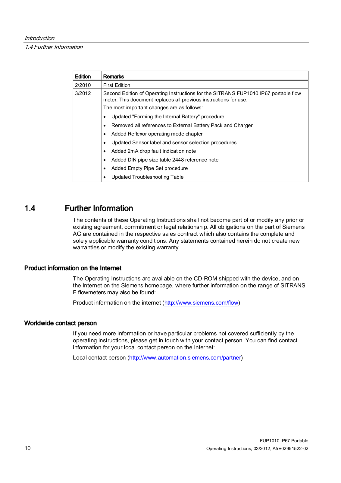
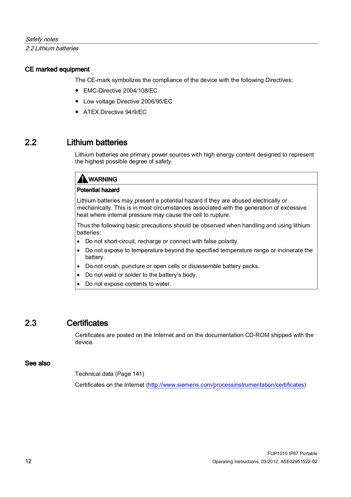
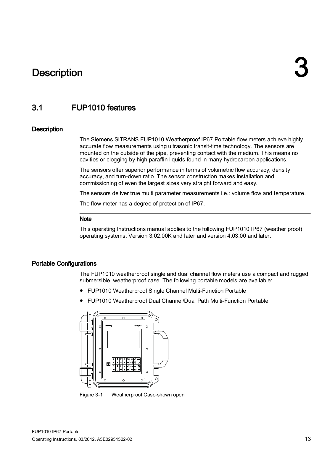
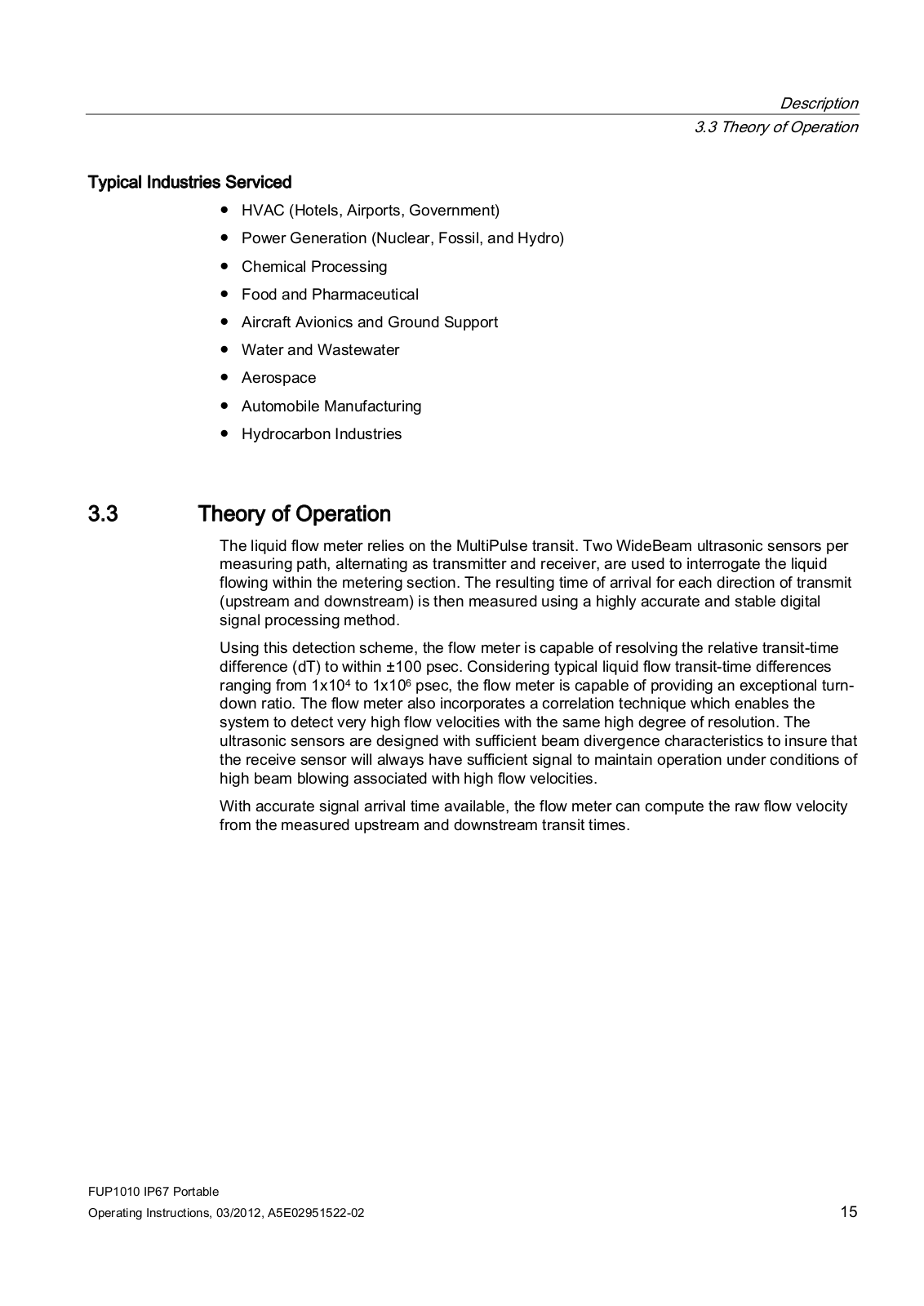
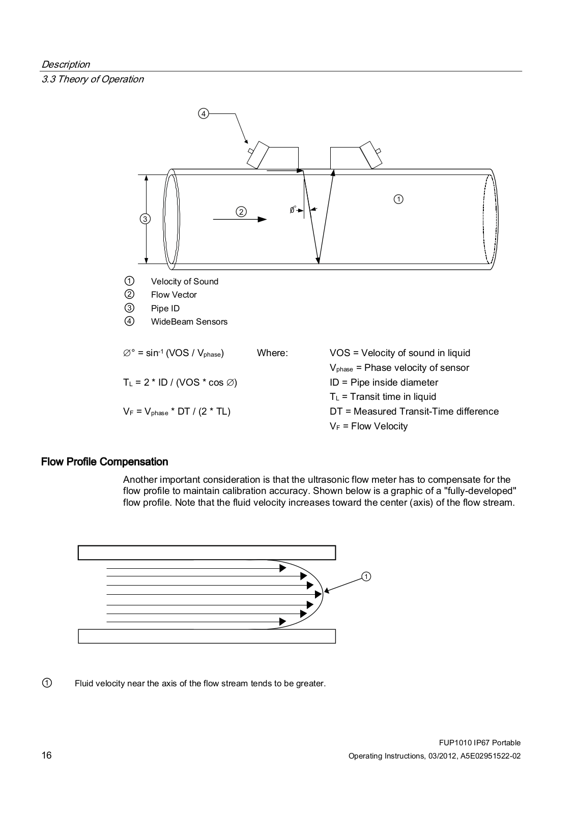
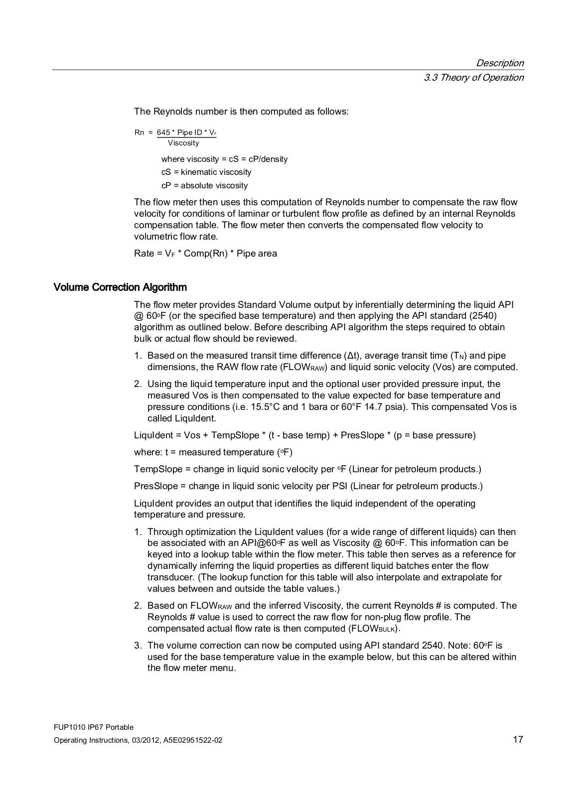
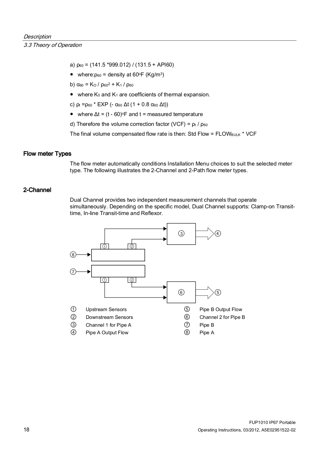
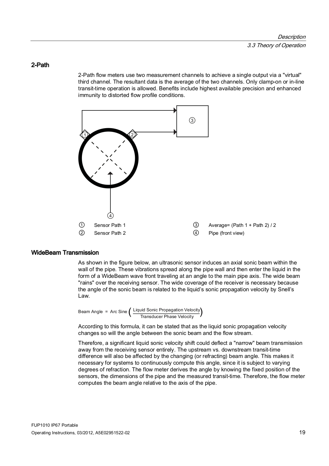
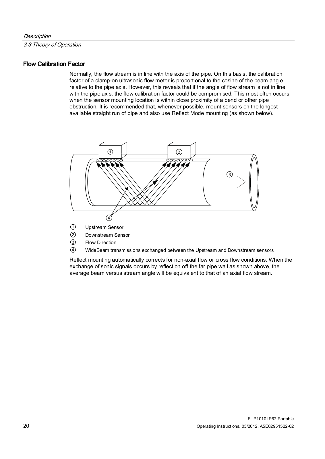
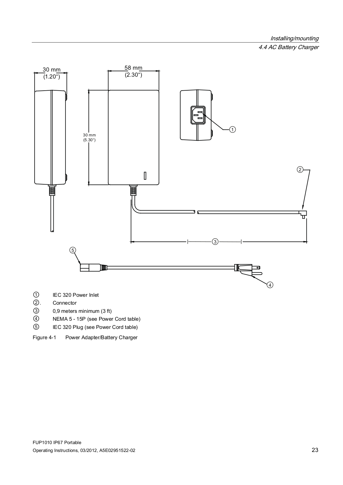

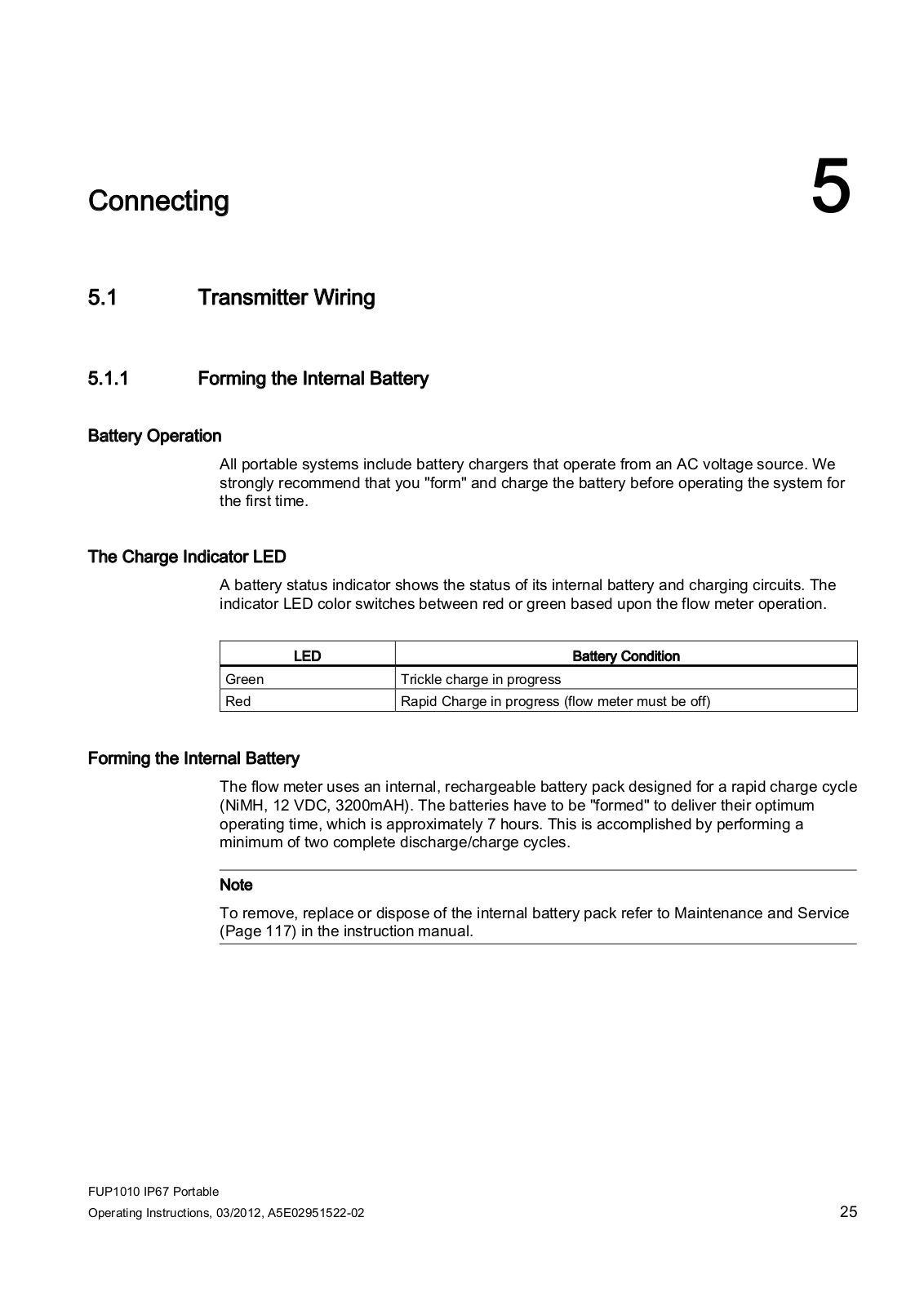
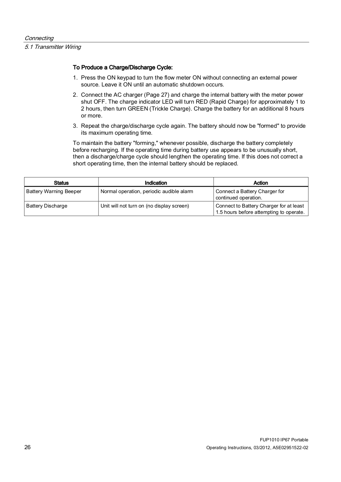
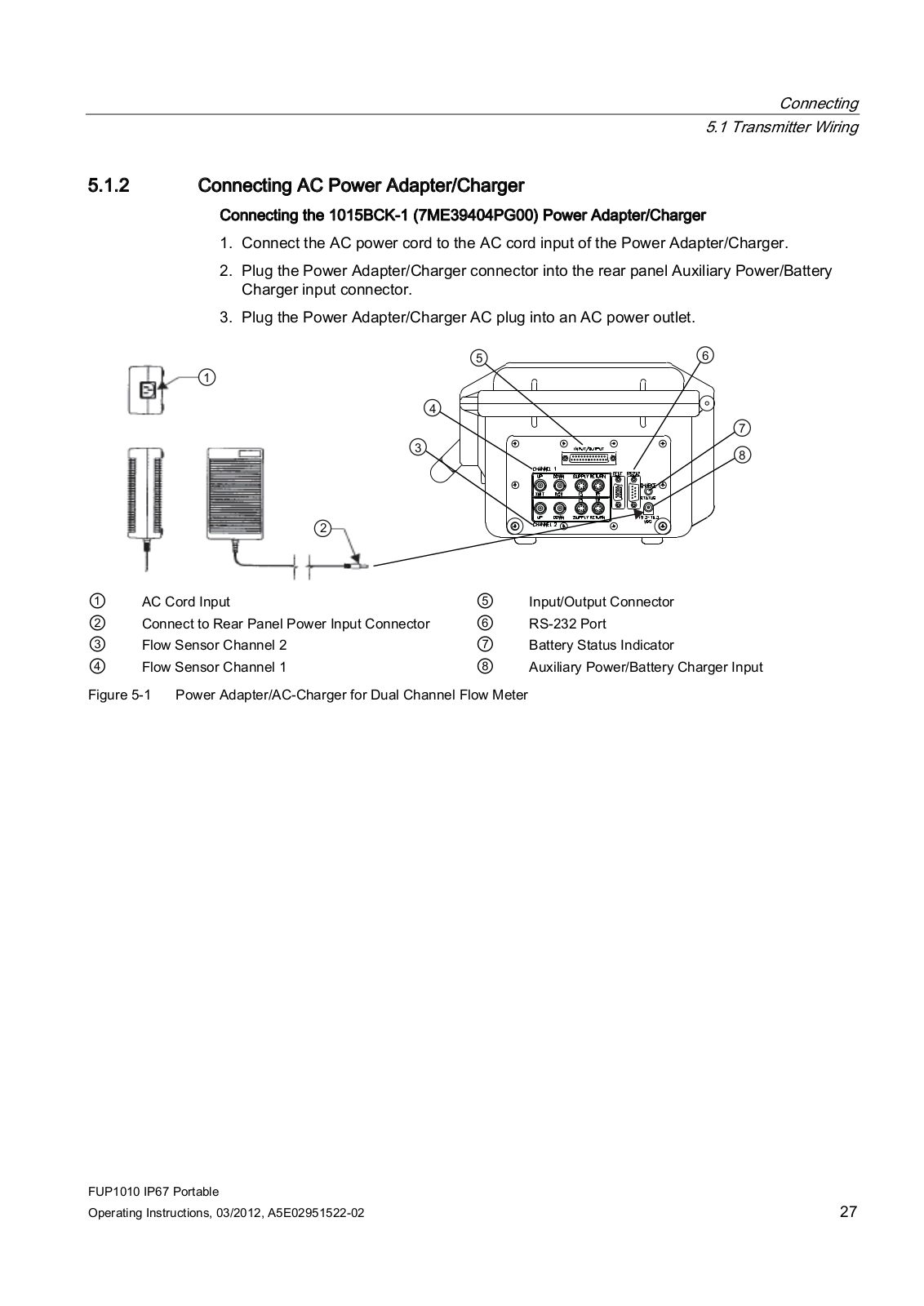
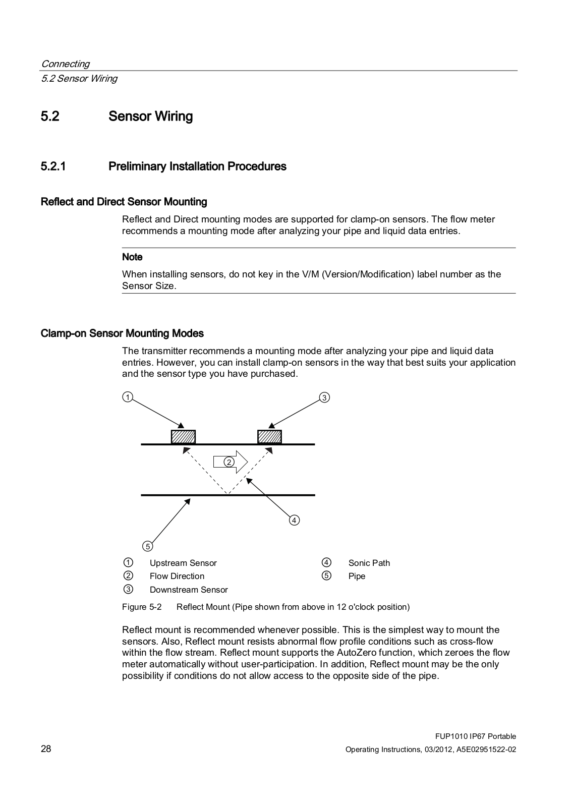


 Loading...