

Siemens SITRANS FUH1010PVDX, SITRANS FUH1010PVX Operating Instructions Manual

Ultrasonic flowmeters
SITRANS FUH1010 IP65 NEMA 7 Compact
Precision Volume 7ME3601-3
Operating Instructions - September 2008
SITRANS F

Special Cautionary Note
Regarding Input Power Wiring
for Compact Explosion Proof Flowmeters
The compact area of the power wiring compartment located under the Rear Housing Cover does not
permit labeling for connecting the flowmeter to its AC or DC power source. The labeled numbers 1,2 and
3 of connector P8 prompt the user to consult the 1010X-7 installation diagram in Appendix B for wiring
details. To avoid damage to the flowmeter, especially in cases where it is difficult or impossible to consult
the 1010X-7 diagram, the correct power supply wiring procedure and corresponding part numbers are
listed below.
1. In addition to confirming the part number of the flowmeter, it is recommended that the actual power
supply module part number be checked for conformation to the power available in the field. Before
applying power to the unit, you may visually confirm the part number of the power supply by removing the front housing cover.
Power Supply Option Code Power Supply P/N User Supplied Power
S 1010X-6SS2 90-230 V AC Single Phase
Z N 010X-6ZNS2 9-36 VDC Negative Ground
ZP 1010X-6ZPS2 9-36 VDC Positive Ground
2. Once the flowmeter’s power supply type has been established and conforms to the available line
power in the field, the P8 power connector can be wired per the table below.
Terminal 1010X-6SS2 1010X-6ZN 1010X-6ZP
Number
1 Hot Positive Positive (Gnd)
2 Neutral Negative (Gnd) Negative
3 Ground Ground Ground
Typical Part Number Construction:
Root Meter Number
Transducer Support
Relay Support
Numeric Display
Power Supply Option
1010X-T2KNZPL2-S2----Safety Rating Option
Language Option


FIELD MANUAL
SITRANS FUH1010PVX/PVDX
NEMA-7 EXPLOSION PROOF
TRANSIT-TIME FLOWMETER
This equipment contains components that are
susceptible to electrostatic discharge (ESD).
Please observe ESD control measures during
the handling and connection process.
Copyright©2008 Siemens Industry, Inc. All Rights Reserved Made in the USA
Field Manual CQO:1010PVXFM-3
Sept. 2008
For use with Operating System
Software Version 3.02.00 or later

Manual Changes
NOTE: For the latest updates and revisions to this field manual go to:
http://support.automation.siemens.com/ and check the Product Manual listing.

MANUAL
ADDENDUM
1010FMA-57
Digital P-Gen
Applications
Procedure Update
Manual Addendum
September 2008
Copyright © 2008 Siemens Industry, Inc. All rights reserved Made in the USA


Manual Addendum
INTRODUCTION
1010FMA-57
Digital P-Gen Applications Procedure Up date
The following Digital P-Gen applications procedure is to be added to the Data Sp
an/Set/Cal Menu
section of the SITRANS liquid and gas flowmeter manuals listed below:
Gas Flowmeter Manuals
FUG1010 IP 65 (NEMA 4X) Clamp-On Gas Flowmeter manual (CQO:1010GCNFM-3)
FUG1010 IP 65 (NEMA 7) Compact Clamp-On Gas Flowmeter manual (CQO:1010GCXFM-3)
FUG1010 IP 65 (NEMA 7) Compact Insert Gas Flowmeter manual (CQO:1010GXFM-3)
Liquid Flowmeter Manuals
FUH1010 IP 65 (NEMA 4X) Clamp-On Flowmeter manual (CQO:1010DVNFM-3)
FUH1010 IP 65 (NEMA 4X) Clamp-On Flowmeter manual (CQO:1010PVNFM-3)
FUH1010 IP 65 (NEMA 7) Compact Clamp-On Flowmeter manual (CQO:1010DVXFM-3)
FUH1010 IP 65 (NEMA 7) Compact Clamp-On Flowmeter manual (CQO:1010PVXFM-3)
DIGITAL P-GEN APPLICATIONS PROCEDURE
Adjusting the PGEN Output
The default setting for the Digital PGEN output provides a 5000 Hz frequency at an assumed maximum
velocity of 100 ft/sec. In certain cases it may be necessary to change this default PGEN value. For
example:
z If the PGEN signal cable is very long, then the added cable capacitance may prevent reliable RTU
pulse detection at or near 5000 Hz. In this case it may be necessary to decrease the PGEN (Pulses
/ Unit Volume) setting using the equation below.
UnitVolumePulses =/
MaxFreq
MaxFlow
Where: MaxFreq = Maximum desired frequency (Hz)
MaxFlow = Maximum flow rate (Unit Volume / second)
z For very low operating flow rates, the pulse frequency may approach the 20 Hz limit of the PGEN
output. In this case it may be necessary to increase the PGEN (Pulses / Unit Volume) setting.
UnitVolumePulses =/
Where: MinFreq = Minimum desired frequency (Hz). Must be greater than 20 Hz!
Note: If STD VOL is selected then the “unit volume” for PGEN will represent Standard Volume,
not actual volume.
Forcing the PGEN Output Frequency
To test the operation of the flowmeter with an RTU, or other pulse counting device, it may be necessary
to force the PGEN output frequency, especially when the pipeline is not flowing during flowmeter
commissioning. This can be accomplished by setting the AnCal diagnostic value to a flow rate
corresponding to the desired frequency output. (Refer to the appropriate paragraph in your manual for
operation of the AnCal function.)
MinFreq
MinFlow
MinFlow = Minimum operating flow rate (Unit Volume / second)
A-1

Manual Addendum
1010FMA-57
The example below demostrates how to calculate the AnCal flow rate based on the desired pulse output
frequency and the entered PGEN (Pulses / Unit volume) setting:
For PGEN setting = 53 Pulses /CU FT and a desired frequency = 1000 Hz
1. Temporarily change flow rate units to CU FT / SEC (Use same volume units as Totalizer.)
2. Set AnCal = 1000 / 53 = 18.868 CU FT / SEC
3. 1000 Hz frequency should now be observed on the PGEN output.
A-2

MANUAL
ADDENDUM
1010FMA-58
Digital Damping
Procedure Update
For Gas & Liquid
Flowmeters
Manual Addendum
September 2008
Copyright © 2008 Siemens Industry, Inc. All rights reserved Made in the USA


Manual Addendum
1010FMA-58
Digital Damping Procedure Update for Gas & Liquid Flowmeters
INTRODUCTION
The following Digital Damping procedure updates are for SITRANS F gas and liquid clamp-on
flowmeters.Replace the Digital Damping Control: (Hot Key 1 and 2) procedure in the “Detection Modes”
section (sub-paragraph: Command Modes) in the appropriate gas and liquid STIRANS F flowmeter
manuals.
FUG1010 Gas Clamp-on Flowmeter Manuals
Digital Damping Control: (Hot Key 1 and 2)
The FUG1010 permits user modification of the digital averaging used by the signal processing routines.
In general, the default damping values selected by the FUG1010 will provide optimal performance over
a wide range of transit time applications. However, in extreme cases of unstable flow , pulsating flow,
low signal levels or high electronic noise it may be necessary to override these default settings to
permit uninterrupted and reliable flow measurement.
Test Facilities Graph Screen
The FUG1010 Graph Screen includes the capability to access a set of command codes, which enable
a user to override a number of default meter settings. The most important parameter is the digital
damping control, which can be accessed by pressing number <1> or <2> on the keypad while in the
Signal Graph Screen mode.
[MinDamp] Command
Pressing the <1> key will cause [MinDamp #] to appear on the command line at the lower left-hand
corner of the screen. The number listed to the right of the command code represents the exponent in
the FUG1010 exponential averaging routine, where the larger the number the greater the digital averaging.
Pressing the <+> key will increase the damping value. Likewise, pressing the <-> key will decrease
the damping value. To exit this mode, press the <0> key on the keypad.
[MaxDamp] Command
Pressing the <2> key will bring up the [MaxDamp] command. The function of this parameter is similar
to the [MinDamp] command described above; however, the two parameters interact in the following
manner . The MinDamp value must not exceed the MaxDamp value, therefore increasing the MinDamp
value above the previous MaxDamp value will set both parameters to the same value. In most cases,
it is preferred that both damping parameters be set to the same value, however , in cases where rapid
response to changes in gas sound velocity for flow rate is required, the two values may be set differently .
In this situation the meter will use the MaxDamp value when conditions are stable, but then switch to
a faster damping value (limited by MinDamp) when a significant change in sound velocity or flow rate
is perceived. To exit this mode, press the <0> key on the keypad.
A-1
Manual Addendum
1010FMA-58
To access the Digital Damping Control using the Test Facilities Graph Screen, proceed as follows:
1. To use the Test Facilities Graph Screen you must have a working site.
2. To activate the Test Facilities Graph Screen:
z In the main menu, scroll to the [Diagnostic Data] menu and select [Test Facilities].
z Scroll down to [Graph], press the <Right Arrow> and highlight [Yes]. Press <ENT> to select.
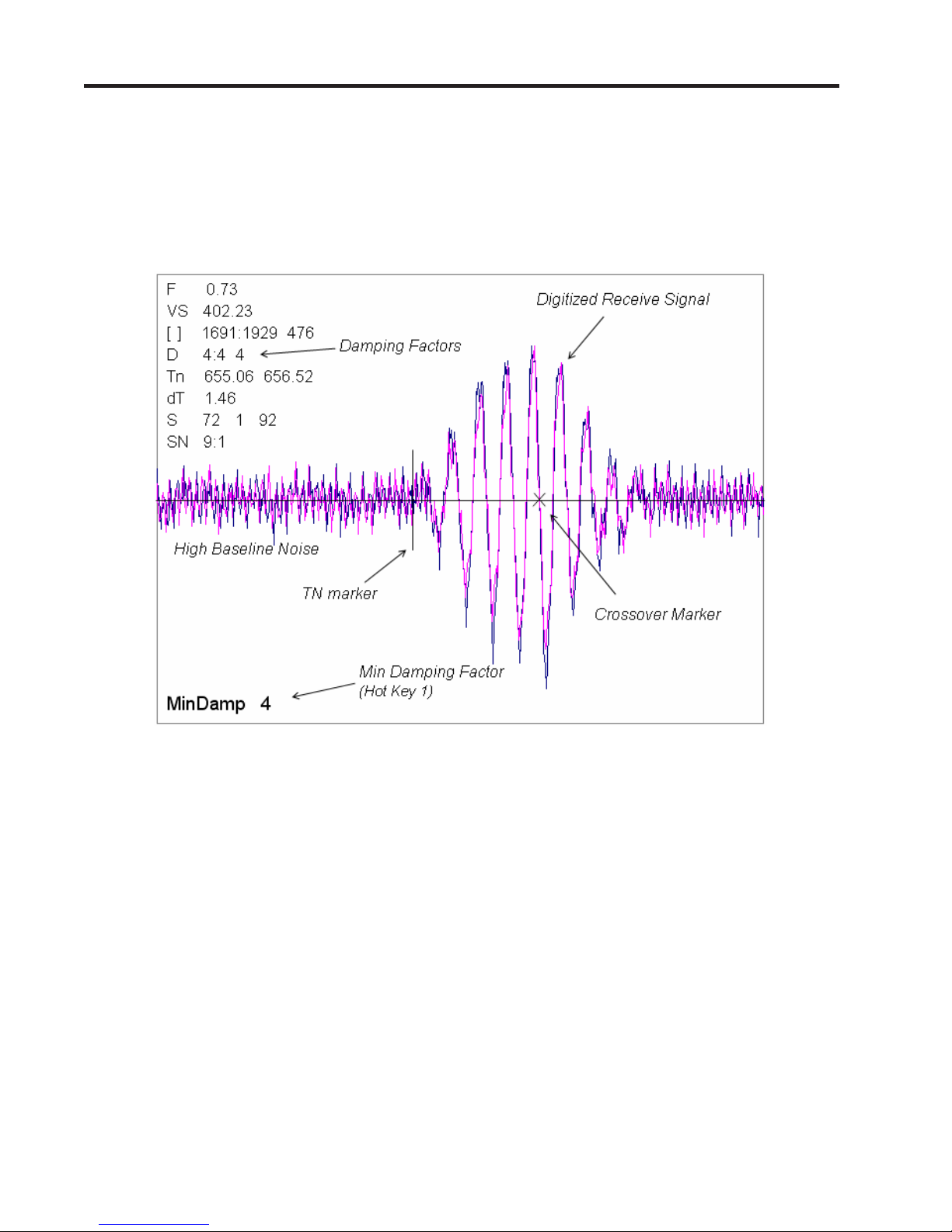
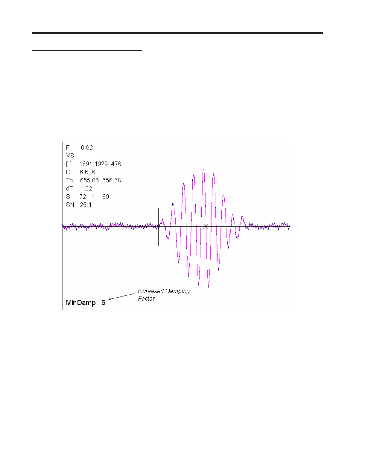
z The Test Facilities Graphic Screen will appear on the meter display as shown below.
Setting the Digital Damping Factor to a value HIGHER than the default value of 4 may be necessary
in cases where the signal to noise ratio (SN) is found to be unacceptably low (<15:1), but only if the
noise is determined to be asynchronous (i.e., not associated with the transmit or flowmeter timing
circuitry) as shown in the signal example above, where the baseline noise has a higher frequency
than the true gas signal.
The following application conditions may require a higher Digital Damping Factor:
z Close proximity to pressure control valves which may generate in-band acoustic noise
z Very low acoustic signal levels (ALC < 40%)
z High electronic noise from variable frequency drives or other external equipment.
A-2
Manual Addendum
1010FMA-58
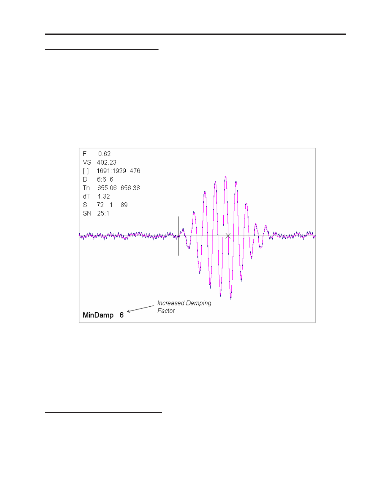
To INCREASE the Digital Damping:
1. Press the <1> key while viewing the Test Facilities Graph Screen as shown above. The damping
control [MinDamp #] should appear on the command line at the lower left-hand corner of the
screen.
Note: The number listed to the right of the command code on the screen represents the
exponent in the exponential averaging routine, where the larger the number represents
the greater the digital averaging. Setting this exponent higher than 7 is generally not
recommended.
2, Pressing the <+> key will increase the MinDamp Factor by one unit for each key press. To exit this
mode, press the <0> key on the keypad.
The above example shows that increasing the Digital Damping reduces asynchronous noise.
Setting the Digital Damping factor to a value LOWER than the default value of 4 may be justified in
cases where pulsating flow is present (such as from a reciprocating compressor) or for the purpose
of diagnosing transient signal behavior. A pulsating flow condition that generates more than +/- 45
degrees of phase jitter will generally cause signal correlation problems when any digital averaging is
used. In this case it may be necessary to completely eliminate the digital averaging by reducing the
Digital Damping Factor to 0. In such a case it may also be necessary to install a narrow band tuned
amplifier (Input Module) if too much asynchronous noise exists.
To DECREASE the Digital Damping:
1. Press the <2> key while viewing the T est Facilities Graph Screen. The damping control [MaxDamp
#] should appear on the command line at the lower left-hand corner of the screen.
2. Pressing the <-> key will decrease the MaxDamp Factor by one unit for each key press. T o exit this
mode, press the <0> key on the keypad.
A-3

Manual Addendum
1010FMA-58
Liquid Clamp-on Flowmeter Manuals
Replace the Digital Damping Control: (Hot Key 1 and 2) procedure in the “Detection Modes” section
(sub-paragraph: Command Modes) in the following flowmeter manuals:
FUS1010 IP 65 (NEMA 4X) Clamp-On Flowmeter manual (CQO:1010NFM-3)
FUE1010 IP 65 (NEMA 4X) Clamp-On Flowmeter manual (CQO:1010ENFM-3)
FUH1010 IP 65 (NEMA 4X) Clamp-On Flowmeter manual (CQO:1010DVNFM-3)
FUH1010 IP 65 (NEMA 4X) Clamp-On Flowmeter manual (CQO:1010PVNFM-3)
FUP1010 IP 40 (NEMA 1) Clamp-On Portable Flowmeter manual (CQO:1010PFM-3)
FUE1010 IP 40 (NEMA 1) Clamp-On Portable Flowmeter manual (CQO:1010EPFM-3)
Digital Damping Control: (Hot Key 1 and 2)
The meter permits user modification of the digital averaging used by the signal processing routines. In
general, the default damping values selected by the METER will provide optimal performance over a
wide range of transit time applications. However, in extreme cases of unstable flow , pulsating flow , low
signal levels or high electronic noise it may be necessary to override these default settings to permit
uninterrupted and reliable flow measurement.
Test Facilities Graph Screen
The Graph Screen includes the capability to access a set of command codes, which enable a user to
override a number of default meter settings. The most important parameter is the digital damping
control, which can be accessed by pressing number <1> or <2> on the keypad while in the Signal
Graph Screen mode.
[MinDamp] Command
Pressing the <1> key will cause [MinDamp #] to appear on the command line at the lower left-hand
corner of the screen. The number listed to the right of the command code represents the exponent in
the meter exponential averaging routine, where the larger the number the greater the digital averaging.
Pressing the <+> key will increase the damping value. Likewise, pressing the <-> key will decrease
the damping value. To exit this mode, press the <0> key on the keypad.
[MaxDamp] Command
Pressing the <2> key will bring up the [MaxDamp] command. The function of this parameter is similar
to the [MinDamp] command described above; however, the two parameters interact in the following
manner. The MinDamp value must not exceed the MaxDamp value, therefore increasing the MinDamp
value above the previous MaxDamp value will set both parameters to the same value. In most cases,
it is preferred that both damping parameters be set to the same value, however , in cases where rapid
response to changes in liquid sound velocity for flow rate is required, the two values may be set
differently . In this situation the meter will use the MaxDamp value when conditions are stable, but then
switch to a faster damping value (limited by MinDamp) when a significant change in sound velocity or
flow rate is perceived. To exit this mode, press the <0> key on the keypad.
A-4
Manual Addendum
1010FMA-58
To access the Digital Damping Control using the Test Facilities Graph Screen, proceed as follows:
1. To use the Test Facilities Graph Screen you must have a working site.
2. To activate the Test Facilities Graph Screen:
z In the main menu, scroll to the [Diagnostic Data] menu and select [Test Facilities].
z Scroll down to [Graph], press the <Right Arrow> and highlight [Yes]. Press <ENT> to select.
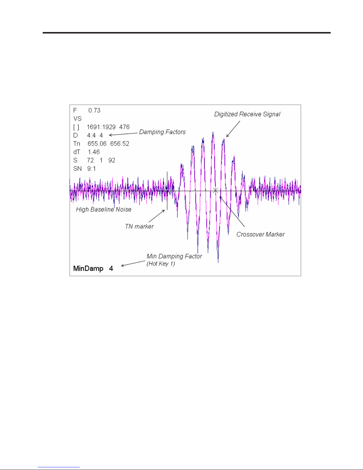
z The Test Facilities Graphic Screen will appear on the meter display as shown below.
1482.1
Setting the Digital Damping Factor to a value HIGHER than the default value of 4 may be necessary in
cases where the signal to noise ratio (SN) is found to be unacceptably low (<15:1), but only if the noise
is determined to be asynchronous (i.e., not associated with the transmit or flowmeter timing circuitry)
as shown in the signal example above, where the baseline noise has a higher frequency than the true
liquid signal.
The following application conditions may require a higher Digital Damping Factor:
z Close proximity to pressure control valves which may generate in-band acoustic noise
z High un-dissolved gas solids content in liquid.
z High electronic noise from variable frequency drives or other external equipment.
A-5
Manual Addendum
1010FMA-58
To INCREASE the Digital Damping:
1. Press the <1> key while viewing the Test Facilities Graph Screen as shown above. The damping
control [MinDamp #] should appear on the command line at the lower left-hand corner of the
screen.
Note: The number listed to the right of the command code on the screen represents the
exponent in the exponential averaging routine, where the larger the number represents
the greater the digital averaging. Setting this exponent higher than 7 is generally not
recommended.
2. Pressing the <+> key will increase the MinDamp Factor by one unit for each key press. To exit this
mode, press the <0> key on the keypad.
1482.1
The above example shows that increasing the Digital Damping reduces asynchronous noise.
Setting the Digital Damping factor to a value LOWER than the default value of 4 may be justified in
cases where pulsating flow is present (such as from a reciprocating pump) or for the purpose of
diagnosing transient signal behavior. A pulsating flow condition that generates more than +/- 45 degrees
of phase jitter will generally cause signal correlation problems when any digital averaging is used. In
this case it may be necessary to completely eliminate the digital averaging by reducing the Digital
Damping Factor to 0.
To DECREASE the Digital Damping:
1. Press the <2> key while viewing the Test Facilities Graph Screen. The damping control [MaxDamp
#] should appear on the command line at the lower left-hand corner of the screen.
2. Pressing the <-> key will decrease the MaxDamp Factor by one unit for each key press. T o exit this
mode, press the <0> key on the keypad.
A-6

MANUAL
ADDENDUM
SETUP PROCEDURE FOR
WET-FLOW CALIBRATED
1010FMA-4
1010 SYSTEMS
System 1010 Uniflow
Portable & NEMA
Flowmeter Systems
Manual Addendum
July 2002
FOR TECHNICAL ASSISTANCE: FOR GENERAL INFORMATION:
Call: (800) 333-7421 Website: www.sea.siemens.com/ia
(631) 231-3600 E-mail: info.ultrasonicflow@siemens.com
Fax: (631) 231-3334 Or: sales.ultrasonicflow@siemens.com
E-mail: TSG.ultrasonicflow@siemens.com
Copyright©2008 Siemens Industry, Inc. All Rights Reserved Made in the USA


Manual Addendum
SETUP PROCEDURE FOR “WET-FLOW CALIBRATED” 1010 SYSTEM
Caution: DO NOT use the field manual installation procedure to startup a wet-flow
calibrated system. Doing so could void the calibration by corrupting essential data. This addendum contains the only authorized instructions to
be used when commissioning a wet-flow calibrated 1010 system.
1. INTRODUCTION
When the system 1010 is wet-flow calibrated, the flow computer stores the installation parameters in its storage memory. Each flow calibration is assigned a unique site name. Usually, the
site name corresponds to the pipe size. For example, a 3-inch carbon steel, schedule 40 pipe
would be given the name “3CS40.”
The flow calibration report issued with each wet-flow calibration, includes a flow calibration
“Diagnostic Data Sheet.” This data sheet lists the site name and other necessary information
(such as transducer serial number and spacing information), for setting-up the flowmeter. A
wet-flow calibration applies to a specific flowmeter and set of transducers; identified by serial
numbers on the diagnostic data sheet.
1010FMA-4
NOTE: In order for the flow calibration to be valid, the flow computer and transducers
being used must have the same serial numbers as those listed for the site on
the Calibration Diagnostic Data Sheet.
2. SETUP PROCEDURE
2.1 Transducer Installation
2.1.1 Refer to the diagnostic data sheet to find the mounting mode (Direct or Reflect) used
during the wet-flow calibration. Review the transducer installation guidelines in your 1010
field manual.
2.1.2 Refer to the diagnostic data sheet for the transducer spacing index utilized during the
flow calibration. Using the mounting configuration employed during the flow calibration,
install the transducers on the pipe at the above noted spacing positions in accordance
with the instructions provided on the transducer installation drawings.
2.1.3 Attach the transducer cables noting that the cable marked “UP” attaches to the transducer closest to the source of flow.
NOTE: Before proceeding further, ensure that the pipe is full of liquid. It is not impor-
tant at this point that it be flowing.
1
July 2002

Manual Addendum
2.2 Flowmeter Setup
NOTE: The following instructions require the use of the keypad and the menu. The
installer should become familiar with their use before proceeding further.
2.2.1 Switch the flowmeter on. Press the <MENU> key.
2.2.2 On multi-channel flowmeters, use the arrow keys to select [Dual Channel Flow] or
[Dual Beam Flow] depending on the mode utilized for the wet-flow calibration.
2.2.3 Use the arrow keys to select either [Clamp-on], [Flow Tube] or [Clamp-on Spool].
2.2.4 Select [Full Site Setup] and use the <Right Arrow> to select [Channel Setup]; then
select [Recall Site Setup].
2.2.5 Use the <Down Arrow> to scroll to the site name indicated on the Calibration Diagnostic Data Sheet. Then press <ENT>.
2.2.6 The meter will perform a momentary “Makeup” routine that will take a few seconds and
then begin operation.
1010FMA-4
2.2.7 Refer to your 1010 field manual for instructions on setting zero flow.
NOTE: Setting zero flow must be performed each time the transducers are installed.
The zero adjustment has no effect on the wet-flow calibration data or the calibration (Kc) factor.
2.2.8 Using the arrow keys, scroll to the Data Span/Set/Cal menu location. V erify that the [Kc]
(calibration) factor matches the value indicated on the diagnostic data sheet.
2.2.9 If you are measuring a liquid other than ambient water, select the [Liquid Class] menu
cell and <Down Arrow> from there to [Viscosity]. Enter the correct viscosity for the
liquid you will be monitoring.
2.2.10 Setup is now complete. Press the <MENU> key twice to view the flow rate display . DO
NOT utilize the [Save Site] command when it appears.
2.2.1 1 When measurements are completed, simply turn off the meter . DO NOT save the site.
This might contaminate the wet-flow calibration data already stored.
NOTE: Contact Siemens’ Technical Services Department if any flow calibration data is
accidentally removed or overwritten.
2
July 2002

Manual Addendum
3. TRANSFER INSTALL FUNCTION
All 1010 flowmeter operating systems (version 3.00.20 and greater) include the installation facility called “Transfer Install.” This function permits the transducers to be repositioned while maintaining all calibration parameters and operation established during the water calibration. The
Transfer Install function allows the transducers to be optimally positioned for a different fluid,
without the need for a new Initial Makeup procedure.
NOTE: Prior to performing Transfer Install make sure that the water calibration proce-
dure was performed and a saved active site exists.
3.1 Transfer Install Procedure
To initiate the Transfer Install function, proceed as follows:
3.1.1 In the Application Menu press the <Right Arrow> to select the [Liquid Class] menu cell.
Scroll and highlight [Estimated Vs m/s] from the option list.
3.1.2 Use the numeric keys to change the Estimated Vs to the Estimated Vs value of the
customer selected liquid.
3.1.3 To enter new Estimated Vs value press <ENT>.
1010FMA-4
3.1.4 Proceed to the Pick/Install Xdcr menu and select the same transducer, mounting mode
and spacing offset that was selected for the water calibration.
3.1.5 Re-space the transducers to the index position indicated by the flowmeter.
3.1.6 Scroll to the [Install Completed?] menu cell and select [Transfer Install] from the option
list.
NOTE: If [Transfer Install] does not appear in the option list then either the Estimated
Vs or the transducer size was improperly entered. In this case, recall the water
calibration site and start the procedure again at Step 3.1.1 above.
3.1.7 For MultiPath systems repeat Step 3.1.6 above for the remaining paths.
3.1.8 The flowmeter should now be operational at the new spacing location.
NOTE: Depending on the size of the pipeline, the change in the estimated sonic veloc-
ity (Vs) and the repositioning of transducers, the flowmeter may not operate out
of Fault even if the spool or pipe is filled with liquid. This can be expected when
performing a Transfer Inst all for liquified gases or for clamp-on natural gas flowmeters.
3.2 Saving New Transfer Install Site
3.2.1 To save the Transfer Installed site, scroll to the Channel Setup menu and press the
<Right Arrow>. Press the <Right Arrow> again to select the [Save/Rename] menu cell.
3.2.2 Use the numeric keys to rename the Transfer Installed site with the same site name
used in Step 3.1.2 above, but with a “T” appended to the end of the site name (e.g.,
3CS40T).
3.2.3 Press <ENT> to store data.
3
July 2002


Table Of Contents
CQO:1010PVXFM-3
TABLE OF CONTENTS
Section 1
1. Introduction To The FUH1010PVX/PVDX NEMA-7 Flowmeter ........................... 1-1
1.1 System Hardware Description ...........................................................................1-1
1.2 Introduction To The FUH1010PVX Operating System .......................................1-2
1.2.1 Installation Menu Overview .............................................................................. 1-2
1.2.2 Overview Of Real-Time Data Collection ............................................................ 1-2
1.2.3 Standard Features ............................................................................................. 1-3
Integral Datalogger ...................................................................................... 1-3
Analog Outputs ........................................................................................... 1-3
Performance ............................................................................................... 1-3
1.3 Description Of Channel Functions (FUH1010PVDX Systems only) ................... 1-4
1.4 Clamp-On Transit-Time Theory Of Operation .................................................... 1-4
Wide Beam Transmission ............................................................................. 1-5
Flow Calibration Factor ................................................................................ 1-5
Section 2
2. Getting Started .................................................................................................. 2-1
2.1 Important Safety Considerations ...................................................................... 2-1
2.2 Power Connections............................................................................................ 2-1
2.2.1 Input Power Connector (P8) And Fuse (F1) ....................................................... 2-1
2.2.2 Power Supply Wiring ..........................................................................................2-2
2.3 The Menu Lockout Switch ................................................................................. 2-3
2.4 Flowmeter Installation Summary ...................................................................... 2-3
FUH1010PVX Interconnection Diagram ........................................................ 2-4
2.5 Choosing A Programming Interface .................................................................. 2-5
2.5.1 Overview Of The Magnetic Wand Interface ...................................................... 2-5
2.5.2 Overview Of The RS-232 Interface..................................................................... 2-5
2.6 Installation Menu Operation With The Magnetic Wand ..................................... 2-6
2.6.1 Accessing And Leaving The Installation Menu.................................................. 2-6
2.6.2 FUH1010PVX Installation Menu Structure ......................................................... 2-7
The Meter Type Menu ................................................................................... 2-7
The Installation Menu Structure ..................................................................... 2-7
Meter Facilities Menu ................................................................................. 2-12
2.6.3 How To Use The Magnetic Wand To Enter Data............................................... 2-13
How To Select Items From An Option List .................................................... 2-13
A Note On Multiple Select Option Lists ........................................................ 2-14
How To Enter Numeric Data .......................................................................2-14
How To Enter Alphanumeric Strings ............................................................2-16
2.7 How To Use The RS-232 Interface ....................................................................2-17
2.7.1 The RS-232 Interface Cable .............................................................................. 2-17
2.7.2 Establishing Communications Using HyperTerminal™ ...................................2-17
2.7.3 Accessing The Installation Menu .....................................................................2-19
Data Display Mode ....................................................................................2-20
2.7.4 Data Entry Using The RS-232 Interface ............................................................2-20
Accessing and Leaving The Menu ...............................................................2-20
2.7.5 Navigating Through The Installation Menu .....................................................2-21
2.7.6 Introduction To The FUH1010PVX Menu Screens ........................................... 2-22
Sect./Page
i

Table Of Contents
2.8 Data Entry Procedures Using The RS-232 Interface ......................................... 2-23
2.8.1 Entering Alphanumeric Strings ....................................................................... 2-23
2.8.2 Selecting Items From An Option List............................................................... 2-24
2.8.3 Entering Numeric Data ....................................................................................2-26
2.9 How To Set Up A Channel For Transit-Time Operation ....................................2-27
Section 3
3. Hardware Installation Guide .............................................................................. 3-1
3.1 Mounting The FUH1010PVX Flow Computer .................................................... 3-1
3.2 Input/Output Wiring ........................................................................................... 3-2
3.2.1 FUH1010PVX Input/Output Wiring (TB1 and TB2).............................................. 3-2
3.2.2 FUH1010PVDX Input/Output Wiring (TB1 and TB2) ........................................... 3-3
3.3 Preparing To Mount The Transducers ................................................................ 3-4
3.3.1 How To Identify 1011 Transducers and Mounting Hardware ............................ 3-4
3.3.2 Selecting A Location For Clamp-On Transducers ............................................... 3-4
3.3.3 Clamp-On Transducer Mounting Modes ........................................................... 3-5
3.3.4 Preparing The Pipe ............................................................................................ 3-6
3.3.5 Sonic Coupling Compound Recommendations ................................................ 3-7
3.3.6 Reflect Mode-Mounting Frames and Spacer Bar ............................................... 3-8
3.3.7 Reflect Mode With Spacer Bar Only ................................................................... 3-9
3.3.8 Direct Mode-Mounting Frames, Spacer Bar and Spacing Guides .................... 3-11
3.3.9 Using 1012T Mounting Trac
3.4 Temperature Sensors (optional) ...................................................................... 3-19
3.4.1 991T Clamp-On Temperature Sensor .............................................................. 3-19
3.4.2 991TW Thermowell Temperature Sensor ........................................................ 3-19
3.5 Notes 1010 Analog Input Modules .................................................................. 3-20
3.6 Clamp-On RTD Installation Notes ..................................................................... 3-20
CQO: 1010PVXFM-3
Sect./Page
Typical FUH1010PVX Installation Menu Screen ............................................ 2-22
Explanations Of Installation Menu Callouts ...................................................2-22
Multiple Select Option Lists ......................................................................... 2-26
How To Access The Channel Setup Menu And Create A Site .........................2-27
ks.......................................................................... 3-15
Installing a 1012T Mounting Track in Reflect Mode ....................................... 3-15
Installing a 1012T Mounting Track in Direct Mode ........................................ 3-17
Section 4
4. FUH1010PVX Application Notes ........................................................................ 4-1
4.1 To Obtain Technical Assistance .........................................................................4-1
4.2 Considerations For Critical Applications ............................................................ 4-1
4.3 Pipe Considerations For Clamp-On Transducers ...............................................4-2
4.3.1 Pipe Dimensions ............................................................................................... 4-2
4.3.2 Picking The Appropriate Transducer ................................................................. 4-2
4.3.3 Flow Velocity Range .......................................................................................... 4-2
4.3.4 Overview of System Performance .................................................................... 4-3
4.3.5 Accuracy ............................................................................................................ 4-3
4.3.6 Repeatability ...................................................................................................... 4-3
4.3.7 Data Stability ...................................................................................................... 4-3
Data Scatter ................................................................................................ 4-3
Data Drift .................................................................................................... 4-3
4.4 Flow Conditions .................................................................................................4-4
ii

Table Of Contents
4.4.1 Low Flow Rates ..................................................................................................4-4
4.4.2 Flow Data Scatter and Damping ........................................................................ 4-4
4.4.3 Notes On Liquid Conditions............................................................................... 4-5
4.4.4 Erroneous Liquid Parameter Specification ........................................................ 4-5
4.4.5 Liquid Compatibility .......................................................................................... 4-5
4.4.6 Aeration ............................................................................................................. 4-5
4.4.7 Slurries ............................................................................................................... 4-6
4.4.8 Two-Phase Liquids .............................................................................................4-6
4.4.9 Viscous Liquids .................................................................................................. 4-6
4.4.10 Temperature and Pressure Ratings ................................................................... 4-6
4.5 Overview Of FUH1010PVX Memory Resources ................................................ 4-6
4.6 Reference Tables ............................................................................................... 4-7
CQO:1010PVXFM-3
Sect./Page
FUH1010 Damping and Slewing Controls .....................................................4-4
Time Average.............................................................................................. 4-4
SmartSlew ..................................................................................................4-4
Sonic Velocity (m/s) for Common Liquids @ 68ºF ......................................... 4-7
DV Liquid Tables .......................................................................................... 4-7
Sonic Velocity for Pure Water @ Various Temperatures (m/s) ........................ 4-8
Vps Values (in inches/second) For Some Common Metals ............................ 4-8
Sonic Velocity Of Pure Water Relative To Temperature ................................... 4-9
System 1010 Reynolds Compensation Factor ............................................. 4-10
Terminology Chart .....................................................................................4-11
Section 5
5. The FUH1010PVX Installation Menu ................................................................. 5-1
General Installation Menu Notes ................................................................... 5-1
5.1 The Chan/Path Setup Menu ............................................................................... 5-2
Chan/Path Setup Menu Structure .................................................................. 5-2
5.1.1 How To Recall A Site Setup ................................................................................ 5-2
5.1.2 How To Enable And Disable A Measurement Channel ..................................... 5-3
5.1.3 How To Create/Name A Site Setup .................................................................... 5-4
5.1.4 How To Enable/Disable Site Security ................................................................. 5-4
5.1.5 How To Delete A Site Setup .............................................................................. 5-5
5.1.6 How To Save/Rename A Site Setup ................................................................... 5-5
5.2 The Pipe Data Menu .......................................................................................... 5-6
Pipe Data Menu Structure ............................................................................. 5-8
5.2.1 How To Select A Pipe Class ................................................................................ 5-9
5.2.2 How To Select A Pipe Size ................................................................................. 5-9
5.2.3 How To Enter The Pipe OD (in. or mm) ............................................................ 5-10
5.2.4 How To Select A Pipe Material ......................................................................... 5-10
5.2.5 How To Enter The Wall Thickness .................................................................... 5-10
5.2.6 Liner Material ................................................................................................... 5-11
5.2.7 Liner Thickness ................................................................................................ 5-11
5.2.8 ThermExp Coef................................................................................................ 5-12
5.2.9 Mod of Elast PSI ............................................................................................... 5-12
5.3 The Application Data Menu ............................................................................. 5-12
Application Data Menu Structure ................................................................. 5-13
5.3.1 How To Select A Liquid Class ...........................................................................5-14
How to Edit the Estimated Vs (liquid sonic velocity) ..................................... 5-15
iii

Table Of Contents
5.3.2 Activating The Liquid Table ............................................................................. 5-16
5.3.3 How To Select A Pipe Temperature Range ...................................................... 5-20
5.3.4 Pipe Configuration .......................................................................................... 5-20
5.4 The Pick/Install XDCR Menu ............................................................................. 5-22
5.4.1 How To Select A Transducer Model ................................................................. 5-23
5.4.2 How To Select A Transducer Size ..................................................................... 5-24
5.4.3 How To Select A XDCR Mount Mode ................................................................ 5-25
5.4.4 Reviewing The Spacing Method ...................................................................... 5-25
5.4.5 How To Use The Spacing Offset ...................................................................... 5-25
5.4.6 The Number Index Menu Cell ......................................................................... 5-26
5.4.7 The Ltn Menu Cell ............................................................................................ 5-26
5.4.8 How To Use [Install Complete?] ...................................................................... 5-26
5.4.9 The Empty Pipe Set Menu ............................................................................... 5-30
5.4.10 Zero Flow Adjust Menu ................................................................................... 5-31
5.5 The Operation Adjust Menu ............................................................................ 5-35
5.5.1 Damping Control ............................................................................................. 5-36
5.5.2 Deadband Control ........................................................................................... 5-36
5.5.3 Memory/Fault Set ............................................................................................ 5-37
5.6 The Flow/Total Units Menu.............................................................................. 5-37
5.6.1 Flow Volume Units .......................................................................................... 5-40
5.6.2 Flow Time Units .............................................................................................. 5-40
5.6.3 Flow Display Range ......................................................................................... 5-41
CQO: 1010PVXFM-3
Sect./Page
How to Edit the Viscosity (cS) Setting .......................................................... 5-15
How to Edit the Density (SG) Setting ........................................................... 5-15
Setting The Liquid Slope ............................................................................. 5-16
Setting The Pressure Slope ......................................................................... 5-17
The Reference Base Temperature ............................................................... 5-18
Setting The LiquIdent
TM
Index ...................................................................... 5-18
Index Value ......................................................................................... 5-19
Viscosity .............................................................................................. 5-19
Visc Slope ........................................................................................... 5-19
Pipe Configuration Menu Structure .............................................................. 5-21
Additional Compensation Tables ................................................................. 5-21
Pick/Install Xdcr Menu Structure .................................................................. 5-24
Force Transmit Procedure .......................................................................... 5-28
How to Use the Actual MTY Command ....................................................... 5-30
How to Use the MTYmatic Command ......................................................... 5-31
How to Use the Set Empty Command ......................................................... 5-31
AutoZero .................................................................................................. 5-31
Actual Zero ............................................................................................... 5-32
ReversaMaticTM.......................................................................................... 5-32
ZeroMaticTM............................................................................................... 5-32
Using Actual Zero ...................................................................................... 5-32
Using ReversaMatic ................................................................................... 5-33
ZeroMatic (optional function) ..................................................................... 5-34
Operation Adjust Menu Structure ................................................................ 5-35
Memory Delay (sec).................................................................................. 5-37
The Flow/Total Units Menu Structure............................................................ 5-38
Totalizer Controls ....................................................................................... 5-39
iv

Table Of Contents
5.6.4 Flow Display Scale ........................................................................................... 5-41
5.6.5 Total Volume Units .......................................................................................... 5-41
5.6.6 Totalizer Scale .................................................................................................. 5-42
5.6.7 Total Resolution ............................................................................................... 5-43
5.6.8 Totalizer Mode ................................................................................................. 5-43
5.6.9 Batch/Sample Total .......................................................................................... 5-43
5.6.10 Reset Totalizer ................................................................................................. 5-43
5.7 The Data Span/Set/Cal Menu ........................................................................... 5-43
5.7.1 Span Data......................................................................................................... 5-45
5.7.2 Set Alarm Levels .............................................................................................. 5-47
5.7.3 Calibrate Flow Rat
5.8 The Datalogger Setup Menu ........................................................................... 5-52
5.8.1 Datalogger Mode ............................................................................................. 5-53
5.8.2 Datalogger Data ............................................................................................... 5-54
5.8.3 Log Time Interval............................................................................................. 5-55
5.8.4 Datalogger Events ........................................................................................... 5-55
5.9 The I/O Data Control Menu .............................................................................. 5-56
5.9.1 Analog Out Setup ............................................................................................ 5-58
CQO:1010PVXFM-3
Sect./Page
The Data Span/Set/Cal Menu Structure ........................................................ 5-44
Pgen ......................................................................................................... 5-46
Max Flow .................................................................................................. 5-46
Min Flow ................................................................................................... 5-46
Max LiquIdent ............................................................................................ 5-47
Min LiquIdent ............................................................................................. 5-47
Max Vs m/s ............................................................................................... 5-47
Min Vs m/s ................................................................................................ 5-47
Max Viscosity cS ........................................................................................5-47
Min Viscosity cS ......................................................................................... 5-47
Max Temperature ...................................................................................... 5-47
Min Temperature ....................................................................................... 5-47
Hi Flow ..................................................................................................... 5-48
Low Flow .................................................................................................. 5-48
High Viscosity cS ....................................................................................... 5-48
Low Viscosity cS ........................................................................................ 5-48
High Temperature...................................................................................... 5-48
Low Temperature ...................................................................................... 5-48
Interface Vs m/s ........................................................................................ 5-48
Aeration % ................................................................................................ 5-48
Makeup Latch ............................................................................................ 5-49
e and Calibration Tables ..................................................... 5-50
Intrinsic ..................................................................................................... 5-50
Kc Calibration ............................................................................................ 5-50
Kc Factor ................................................................................................... 5-51
Selecting Kc Factor .................................................................................... 5-51
Calibration Tables 1 through 3 .................................................................... 5-51
The Datalogger Setup Menu Structure ......................................................... 5-53
Alarm Letter Codes And Descriptions .......................................................... 5-54
The I/O Data Control Menu Structure ........................................................... 5-57
FUH1010PVX Analog Outputs .................................................................... 5-58
Analog Out Setup Data Categories ............................................................. 5-58
v

Table Of Contents
5.9.2 Relay Setup ...................................................................................................... 5-59
5.9.3 Analog Input Setup.......................................................................................... 5-60
5.10 The Meter Facilities Menu ............................................................................... 5-61
5.10.1 Preferred Units ................................................................................................ 5-62
5.10.2 The Table Setups Menu ................................................................................... 5-62
5.10.3 Transducer Type Menu .................................................................................... 5-65
5.10.4 The Datalogger Control Menu ......................................................................... 5-67
5.10.5 The Memory Control Menu.............................................................................. 5-69
5.10.6 The Analog Output Trim Menu ........................................................................5-70
5.10.7 The RTD Calibrate Menu (optional) ................................................................. 5-71
5.10.8 The Clock Set Menu ......................................................................................... 5-72
5.10.9 RS-232 Setup .................................................................................................... 5-73
5.10.10 System Info ..................................................................................................... 5-76
5.10.11 Data Display Screen ......................................................................................... 5-76
CQO: 1010PVXFM-3
Sect./Page
Assigning Io Output Functions .................................................................... 5-58
Assigning Pgen Output Functions ............................................................... 5-58
Assigning Relay 1 Functions ....................................................................... 5-59
Relay Option List ........................................................................................ 5-59
Setting up the Analog Current Input ............................................................ 5-60
Pipe Table ................................................................................................. 5-62
Pipe Table Menu Structure .......................................................................... 5-63
Create/Edit Pipe ......................................................................................... 5-64
Delete Pipe................................................................................................ 5-65
Transducer Type Menu Structure................................................................. 5-66
Datalogger Control Menu Structure ............................................................. 5-67
Output Datalogger ..................................................................................... 5-67
Circular Memory ........................................................................................ 5-68
Est Log Time Left ....................................................................................... 5-69
Clear Datalogger ....................................................................................... 5-69
Analog Output Trim Menu Structure ............................................................ 5-70
Current Output Trim (Io1 & Io2) .................................................................. 5-70
Pgen Output Trim (Single Channel models only) ..........................................5-70
RTD Calibration By Data Entry ..................................................................... 5-71
Ice Bath RTD Calibration ............................................................................. 5-72
Clock Set Menu Structure ........................................................................... 5-72
Date ......................................................................................................... 5-73
Time ......................................................................................................... 5-73
RS-232 Setup Menu Structure .................................................................... 5-74
Baud Rate ................................................................................................. 5-74
Parity ........................................................................................................ 5-74
Data Bits ................................................................................................... 5-75
Line Feed .................................................................................................. 5-75
Network ID ................................................................................................ 5-75
RTS Key Time ............................................................................................ 5-76
System Info Menu Structure ....................................................................... 5-76
Activating The Display ................................................................................ 5-76
Selecting Display Data Items ...................................................................... 5-77
vi
 Loading...