

Siemens SITRANS FUS380, SITRANS FUE380 Operating Instructions Manual
Operating Instructions
Edition 09/2007 - Revision 05
Order no.: A5E00730100
SFIDK.PS.022.Q5.02
A5E00730100
SITRANS F US
Ultrasonic flowmeter type SITRANS FUS380
Ultrasonic flowmeter type SITRANS FUE380
(type-approved for heat metering)
[
s
Technical Documentation (handbooks, instructions, manuals etc.) for the complete product
range SITRANS F can be found on the internet/intranet via the following link:
English: http://www4.ad.siemens.de/WW/view/en/10806951/133300
]

2
SFIDK.PS.022.Q5.02
Introduction 1
General safety instructions 2
Description 3
Installation 4
Electrical connection 5
Operation 6
Troubleshooting 7
Sealing 8
Technical data 9
Ordering 10
Appendix 11

3
SFIDK.PS.022.Q5.02
Table of contents
1 Introduction . . . . . . . . . . . . . . . . . . . . . . . . . . . . . . . . . . . . . . . . . . . . . . . . . . . . . . . . . . . . . . . . . . . . . 4
1.1 Preface . . . . . . . . . . . . . . . . . . . . . . . . . . . . . . . . . . . . . . . . . . . . . . . . . . . . . . . . . . . . . . . . . . . . . . . . 4
2. General safety instructions . . . . . . . . . . . . . . . . . . . . . . . . . . . . . . . . . . . . . . . . . . . . . . . . . . . . . . . . . 4
2.1 Safety notes . . . . . . . . . . . . . . . . . . . . . . . . . . . . . . . . . . . . . . . . . . . . . . . . . . . . . . . . . . . . . . . . . . . . 4
2.2 Manufacturer’s design and safety statement . . . . . . . . . . . . . . . . . . . . . . . . . . . . . . . . . . . . . . . . . . . 4
3. Description . . . . . . . . . . . . . . . . . . . . . . . . . . . . . . . . . . . . . . . . . . . . . . . . . . . . . . . . . . . . . . . . . . . . . 6
3.1 Product description . . . . . . . . . . . . . . . . . . . . . . . . . . . . . . . . . . . . . . . . . . . . . . . . . . . . . . . . . . . . . . . 6
3.2 Service . . . . . . . . . . . . . . . . . . . . . . . . . . . . . . . . . . . . . . . . . . . . . . . . . . . . . . . . . . . . . . . . . . . . . . . . 6
4. Installation . . . . . . . . . . . . . . . . . . . . . . . . . . . . . . . . . . . . . . . . . . . . . . . . . . . . . . . . . . . . . . . . . . . . . 7
4.1 Installation of sensor compact/remote versions . . . . . . . . . . . . . . . . . . . . . . . . . . . . . . . . . . . . . . . . . 7
4.2 Installation of transmitter compact/remote versions . . . . . . . . . . . . . . . . . . . . . . . . . . . . . . . . . . . . . . 9
4.2.1 General information . . . . . . . . . . . . . . . . . . . . . . . . . . . . . . . . . . . . . . . . . . . . . . . . . . . . . . . . . . . . . . 9
4.2.2 Insulation . . . . . . . . . . . . . . . . . . . . . . . . . . . . . . . . . . . . . . . . . . . . . . . . . . . . . . . . . . . . . . . . . . . . . . 9
4.2.3 Mains powered version . . . . . . . . . . . . . . . . . . . . . . . . . . . . . . . . . . . . . . . . . . . . . . . . . . . . . . . . . . . 9
4.2.4 Wiring diagram for mains power supply, pulse output . . . . . . . . . . . . . . . . . . . . . . . . . . . . . . . . . . . .9
4.2.5 Mains powered units with back-up battery . . . . . . . . . . . . . . . . . . . . . . . . . . . . . . . . . . . . . . . . . . . . 10
4.3 Battery powered version . . . . . . . . . . . . . . . . . . . . . . . . . . . . . . . . . . . . . . . . . . . . . . . . . . . . . . . . . 11
4.4 Installation of the transmitter, remote version . . . . . . . . . . . . . . . . . . . . . . . . . . . . . . . . . . . . . . . . . . 12
4.4.1 Installation of wall/pipe bracket . . . . . . . . . . . . . . . . . . . . . . . . . . . . . . . . . . . . . . . . . . . . . . . . . . . . 12
4.4.2 Connection of transducer cables . . . . . . . . . . . . . . . . . . . . . . . . . . . . . . . . . . . . . . . . . . . . . . . . . . . 1 2
4.4.3 Transducer connection scheme . . . . . . . . . . . . . . . . . . . . . . . . . . . . . . . . . . . . . . . . . . . . . . . . . . . . 13
4.4.4 Wiring diagram, base of connection board . . . . . . . . . . . . . . . . . . . . . . . . . . . . . . . . . . . . . . . . . . . 13
5. Electrical connection . . . . . . . . . . . . . . . . . . . . . . . . . . . . . . . . . . . . . . . . . . . . . . . . . . . . . . . . . . . . 14
5.1 Pulse output A and B setting . . . . . . . . . . . . . . . . . . . . . . . . . . . . . . . . . . . . . . . . . . . . . . . . . . . . . . 14
5.1.1 FUE380 preset pulse output A settings dedicated to energy calculator type SITRANS FUE950 . . 14
5.1.2 FUS380 and FUE380 preset output B settings . . . . . . . . . . . . . . . . . . . . . . . . . . . . . . . . . . . . . . . . 15
5.1.3 Wiring diagram for connection to energy calculator type SITRANS FUE950 . . . . . . . . . . . . . . . . . 16
6. Operation . . . . . . . . . . . . . . . . . . . . . . . . . . . . . . . . . . . . . . . . . . . . . . . . . . . . . . . . . . . . . . . . . . . . . 17
6.1 Flowmeter operation via key and display . . . . . . . . . . . . . . . . . . . . . . . . . . . . . . . . . . . . . . . . . . . . 17
6.2 Operator menu . . . . . . . . . . . . . . . . . . . . . . . . . . . . . . . . . . . . . . . . . . . . . . . . . . . . . . . . . . . . . . . . . 18
6.3 Information symbols . . . . . . . . . . . . . . . . . . . . . . . . . . . . . . . . . . . . . . . . . . . . . . . . . . . . . . . . . . . . . 19
7. Troubleshooting . . . . . . . . . . . . . . . . . . . . . . . . . . . . . . . . . . . . . . . . . . . . . . . . . . . . . . . . . . . . . . . . 19
7.1 Alarm code . . . . . . . . . . . . . . . . . . . . . . . . . . . . . . . . . . . . . . . . . . . . . . . . . . . . . . . . . . . . . . . . . . . . 19
8. Sealing . . . . . . . . . . . . . . . . . . . . . . . . . . . . . . . . . . . . . . . . . . . . . . . . . . . . . . . . . . . . . . . . . . . . . . . 20
8.1 User sealing of the SITRANS FUE380 . . . . . . . . . . . . . . . . . . . . . . . . . . . . . . . . . . . . . . . . . . . . . . . 20
8.2 Verification sealing of the SITRANS FUE380 . . . . . . . . . . . . . . . . . . . . . . . . . . . . . . . . . . . . . . . . . 20
9. Technical data . . . . . . . . . . . . . . . . . . . . . . . . . . . . . . . . . . . . . . . . . . . . . . . . . . . . . . . . . . . . . . . . . 21
9.1 Technical data SITRANS FUS380 and FUE380 . . . . . . . . . . . . . . . . . . . . . . . . . . . . . . . . . . . . . . . 2 1
9.2 Dimensional drawings for FUS380 and FUE380 . . . . . . . . . . . . . . . . . . . . . . . . . . . . . . . . . . . . . . 22
9.2.1 Pipe dimensions for FUS380 and FUE380 . . . . . . . . . . . . . . . . . . . . . . . . . . . . . . . . . . . . . . . . . . .22
10. Ordering . . . . . . . . . . . . . . . . . . . . . . . . . . . . . . . . . . . . . . . . . . . . . . . . . . . . . . . . . . . . . . . . . . . . . . 24
10.1 FUS380 selection and ordering data . . . . . . . . . . . . . . . . . . . . . . . . . . . . . . . . . . . . . . . . . . . . . . . . 24
10.2 FUE380 (type approved) selection and ordering data . . . . . . . . . . . . . . . . . . . . . . . . . . . . . . . . . . 2 6
10.3 Spare parts for FUS380 and FUE380 . . . . . . . . . . . . . . . . . . . . . . . . . . . . . . . . . . . . . . . . . . . . . . . 28
11. Appendix . . . . . . . . . . . . . . . . . . . . . . . . . . . . . . . . . . . . . . . . . . . . . . . . . . . . . . . . . . . . . . . . . . . . . 29
11.1 EC Declaration of Conformity . . . . . . . . . . . . . . . . . . . . . . . . . . . . . . . . . . . . . . . . . . . . . . . . . . .
. . . 29

4
SFIDK.PS.022.Q5.02
1.1 Preface
Introduction 1
These instructions contain all the information required to commission and use the SITRANS FUS
ultrasonic flowmeter types FUS380 and the type-approved flowmeter FUE380 for heat metering
systems.
These instructions are intended to assist personnel performing mechanical installation, electrical
connection and commissioning of the device, as well as service and maintenance engineers.
General safety instructions 2
2.1 Safety notes
For safety reasons it is important that the following points, especially those marked with a warning
sign, are read and understood before the system is installed:
• Installation, connection, commissioning and service must be carried out by personnel who
are qualified and authorized to do so.
• It is very important for any person working with the equipment to read and understand the
instructions and directions provided in this manual and follow instructions and directions
before using the equipment.
• Only personnel authorized and trained by the owner of the equipment may operate the
equipment.
• Installation personnel must ensure that the measuring system is correctly connected in
accordance with the connection diagram.
• For applications involving high working pressures or media that can be dangerous to
people, surroundings, equipment or other in the event of pipe fracture, Siemens recommends
taking precautions such as special placement, shielding or installation of a safety guard or
safety valve prior to installation of the sensor.
• Repair and service may be performed by approved Siemens Flow Instruments personnel
only.
2.2 Manufacturer’s design and safety statement
• Responsibility for the choice of flowmeter pipe material as regards abrasion and corrosion
resistance lies with the purchaser. The effect of any change in process medium during
operation of the meter should be taken into account. Incorrect selection of flowmeter pipe
material could lead to failure of the flowmeter.
• Stresses and loading caused by earthquakes, traffic, high winds and fire damage are not taken
into account during flowmeter design.

5
SFIDK.PS.022.Q5.02
• Do not install the flowmeter such that it acts as a focus for pipeline stresses. External loading
is not taken into account during flowmeter design.
• Please aware about the risk of installing the sensor in a highly vibrating environment.
Parts may shake loose and the complete system must be monitored in that case.
• Flanges and joints as well as related pressure/temperature (p/t) classification has been
described in EN 1092-1. See ferrite steel group 1E1: table 15.
• During operation do not exceed the pressure and/or temperature ratings indicated on the data
label or in this Operating Manual.
• It is recommended that all installations include an appropriate safety valve and adequate
means for draining.
• Under the „Pressure Equipment Directive“ (PED), this product is a presssure accessory and
not approved for use as a safety accessory, as defined by the PED.
• DANGER
Do not unscrew the transducers during pipe operation (especially for DN 50 ... DN 80).
Battery operation:
• When battery operated, SITRANS FUS380 and FUE380 is not covered by the „Low Voltage
Directive“ (LVD). Hence, an installation can be considered in conformance with LVD, only
when the SITRANS FUS380 /FUE380 is connected to equipment conforming to LVD.
• Lithium batteries are primary power sources with high energy content. They are designed to
meet the highest possible safety standard. They may, however, present a potential hazard if
they are abused electrically or mechanically. This is in most circumstances associated with
the generation of excessive heat, where increased internal pressure may cause the cell to
rupture.
Thus the following basic precautions should be observed when handling and using lithium
batteries:
- Do not short-circuit, recharge, overcharge or connect with false polarity.
- Do not expose to temperature beyond the specified temperature range or incinerate the
battery.
- Do not crush, puncture or open cells or disassemble battery packs.
- Do not weld or solder to the body of the battery.
- Do not expose contents to water.
• Lithium batteries are regulated under United Nations Model Regulations on Transport of
Dangerous goods, UN document ST/SGAC.10-1,12th revised edition, 2001. UN no. 3091 class
9 covers lithium batteries packed with or inside the equipment. UN no. 3090 class 9 covers
transportation of batteries on their own.
Thus the following basic precautions should be followed when transporting lithium batteries:
- Transport only in special packaging with special labels and transportation documents.
- Exercise caution in handling, transportation and packaging in order to prevent short
circuiting of the batteries.
- The gross mass of the package is limited according to the type of transportation.
In general, a gross mass below 5 kg is acceptable for all forms of transportation.
• Remove the battery from transmitter before returning the flowmeter to Siemens for service or
warranty claim.

6
SFIDK.PS.022.Q5.02
Description 3
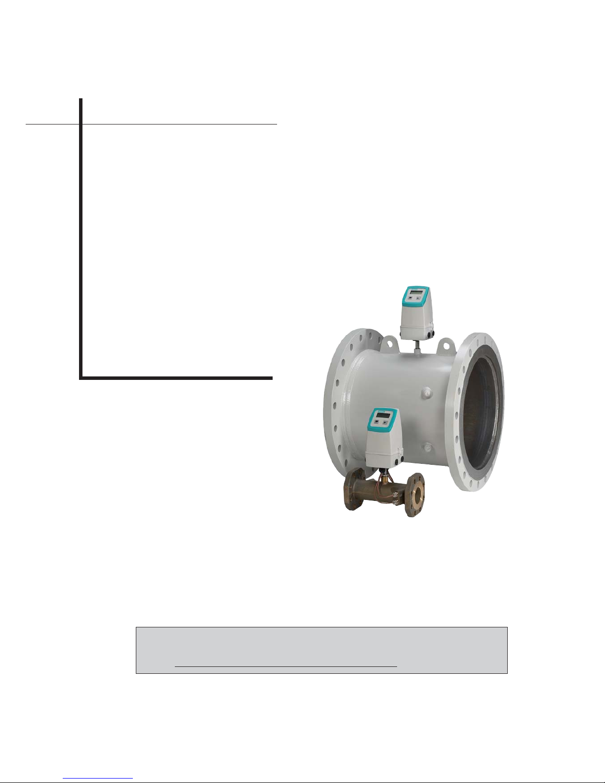
3.1 Product description
The 2-track ultrasonic flowmeter SITRANS FUS380 and approved SITRANS FUE380 comes as
battery or mains powered and is designed to measure water flow in district heating plants, local
stations, substations, chiller plants and other general water applications including treated waste
water.
The SITRANS FUS flowmeter is available in the following variants:
• FUS380: A universal flowmeter with selectable settings.
• FUE380: A type-approved flowmeter dedicated to measure flow in a heating system.
SITRANS FUE380 is approved according to heat meter standards EN 1434
class 2, OIML R75 class 2 and MID.
FUE380 may be marked „neutral“ or have a country-specific approval label,
depending on selection of flowmeter setup when ordering.
Both flowmeter types SITRANS FUS380 and FUE380 are available in either compact or remote
versions and electrical wiring and operation are identical for both types. The maximum permissible
distance between sensor and transmitter is 30 meters.
The flowmeter comes as a transmitter part FUS080 and a sensor part FUS300. This two parts
can be only ordered together as a flowmeter system type FUS380 or FUE380. For FUS380 a spare
part transmitter can be ordered separate (see FI01 catalogue). For FUE380 is this not allowed
according the approvals. For both systems the sensor part cannot be ordered without a
transmitter.
In FUS380 parameters and pulse output are preset from factory and protected via software lock.
A software tool is required to change parameters.
In FUE380 - metrological parameters and pulse output are preset from factory and protected via
hardware lock and sealings to avoid manipulation.
No settings of installation are required as all parameters are set from factory (plug and play).
Maximum temperature compact for DN 50 ... 1200 sensors 2 ... 120 ºC (35,6 ... 248 ºF).
Maximum temperature remote version DN 100 ... 1200 steel sensors 2 ... 200 ºC
(35,6 ... 392 ºF) and for DN 50 ... 80 red brass sensors 2 ... 150 ºC (35,6 ... 302 ºF).
Accessories for correct pipeline assembly and use of flanges gaskets are not Siemens Flow
Instruments A/S responsibility.
3.2 Service
In order to locate and diagnose failures, a software tool for diagnosis and re-programming of
outputs is available. Failure information is available on the display. Failures are stored in memory,
and can be accessed via the infra-red communication port.
(Software for diagnosis and setting of parameters is available from Siemens Automation and
Drives, Process Instrumentation and Analytics).
7
SFIDK.PS.022.Q5.02
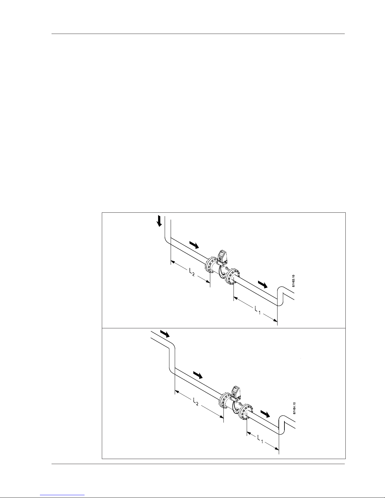
Single bend
Dual bend
1 x 90° bend
L2: Min. 10 x pipe diameter
L1: 3 x pipe diameter
2 x 90° bends in the same plane
L2: Min. 10 x pipe diameter
L1: 3 x pipe diameter
4.1 Installation of sensor compact/remote versions
Requirement for straight inlet before flowmeter
In order to maximise performance it is necessary to have straight inlet and outlet flow conditions
before and after the flowmeter.
Furthermore, a minimum distance between flowmeter and pumps and valves must be
respected.
It is also important to centre the flowmeter in relation to flanges and gaskets.
Make sure that the flowmeter is positioned as low as possible to prevent air from being trapped
in the flowmeter at the transducers.
Find a position on the pipeline where the inlet pipe to the flowmeter has a straight length as
specified below.
Note
For MID approved FUE380 systems the following inlet pipe is recommend:
L2 for sizes > DN 80: 1.5 m (2 m) or
L2 for sizes < DN 65: 10 x DN.
Installation 4
8
SFIDK.PS.022.Q5.02
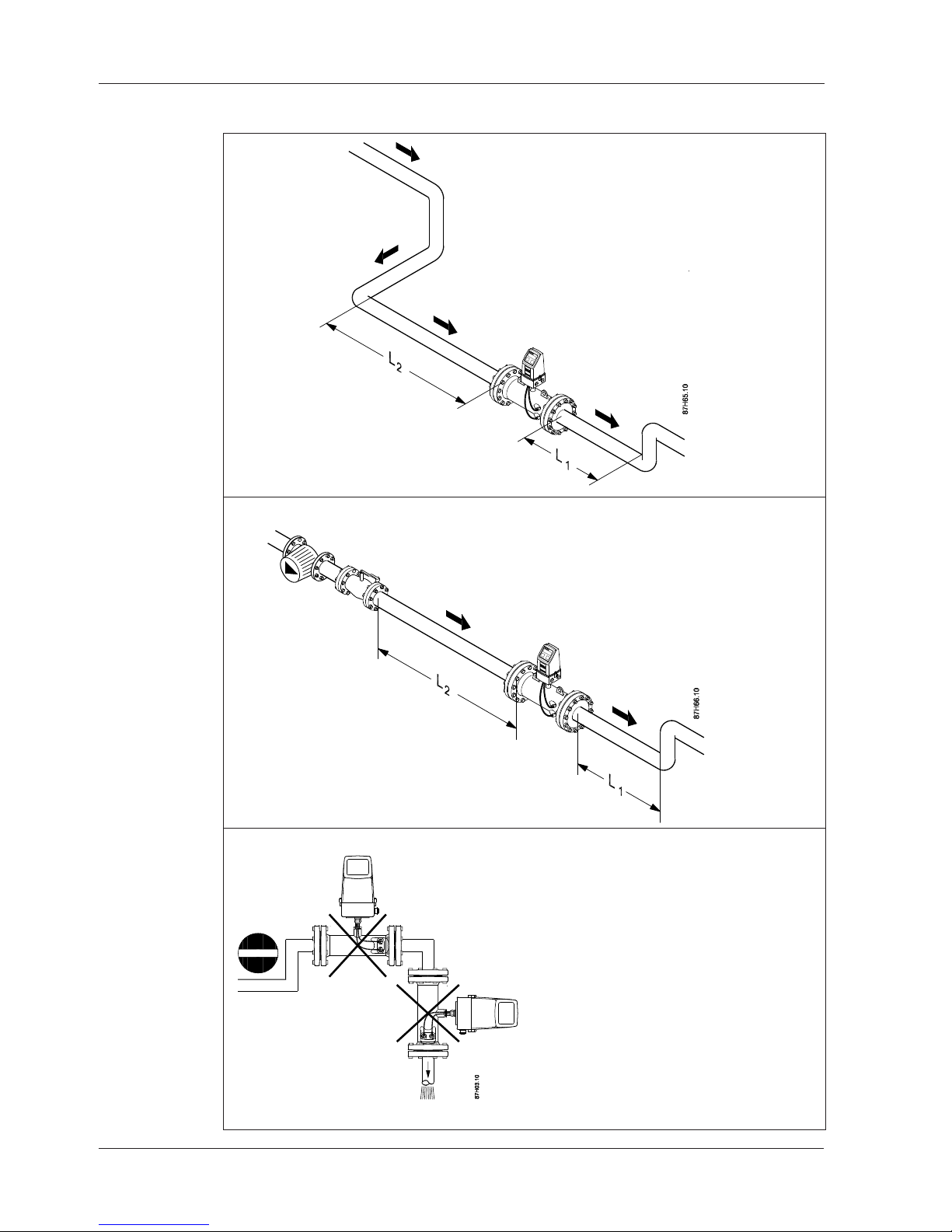
Valves and pumps
Precautions
Avoid installation at the highest point in the
system because air bubbles will be trapped in
the flowmeter.
Avoid installation at a point where there is a
free outlet after the flowmeter.
The flowmeter pipe section may be installed
in either a horizontal or vertical position.
Note
To obtain maximum battery lifetime with the
Lithium Thionyl Chloride battery pack,
Siemens recommends installing the flowmeter
transmitter in an upright position.
3 x 90° bends in two planes
L2: Min. 20 x pipe diameter
L1: 3 x pipe diameter
Valves
L2: Min. 10 x pipe diameter, fully open valve
L1: 3 x pipe diameter
Pumps:
L2: Min. 20 x pipe diameter
L1: 3 x pipe diameter
Triple bend

9
SFIDK.PS.022.Q5.02
4.2 Installation of transmitter compact/remote versions
4.2.1 General information
The transmitter is packed separately - ready for plug-in into the base part.
SITRANS FUS380 and FUE380 may be mains powered or battery powered. Determine the
flowmeter power source type by reading the label or via the product code.
Important:
A transmitter ordered as only battery powered cannot be updated with additional mains power,
because no mains power supply circuits are installed in this transmitter type.
On compact versions, all transducer cables are pre-mounted from factory.
Mounting of output pulse cables is identical for compact and remote versions.
4.2.2 Insulation
Both versions can be insulated.
Siemens always recommends insulation of the sensor in the compact version to prevent heat
transfer to the transmitter. The recommendation applies to both battery powered and mains
powered versions.
4.2.3 Mains powered version
The mains powered version can always be retrofitted with a battery pack.
In the event of power failure the battery will take over the power supply of the unit.
The battery is not of a rechargeable type. The battery must be replaced every 6 years.
At delivery the transmitter may be pre-mounted with a battery pack. Alternatively, the battery
pack must be installed before use. (See section „Battery powered version“).
Note
The male battery plug is not connected to the plug female socket connection upon delivery. This
connection must be made to enable the back-up battery power supply. Please refer to the section
„Battery powered installation“ for further details.
4.2.4 Wiring diagram for mains power supply, pulse output
Always disconnect mains supply before removing the transmitter top part (mains powered units
only).
Important
Cable binder must be fastened to printed circuit board according to drawing.
 Loading...