

Siemens SITRANS FSS200 Installation Manual

SITRANS F
Ultrasonic Flowmeters
FSS200 ultrasonic clamp-on sensors
Installation Manual
Edition
Answers for industry.
08/2017


SITRANS F
Ultrasonic Flowmeters
FSS200 clamp-on sensors
Installation Manual
08/2017
A5E36255466
Introduction
1
Safety notes
2
Installation overview
3
Installing/mounting
4
Connecting
5
Service and maintenance
6
Technical data
7
Dimensions and weight
8
Certificates and support
A
Additional Installation
Instructions
B
-AC
Siemens AG
Division Process Industries and Drives
Postfach 48 48
90026 NÜRNBERG
GERMANY
Document order number: A5E36255466
Ⓟ
Copyright © Siemens AG 2017.
All rights reserved
Legal information Warning notice system
DANGER
indicates that death or severe personal injury will result if proper precautions are not taken.
WARNING
may
CAUTION
indicates that minor personal injury can result if proper precautions are not taken.
NOTICE
indicates that property damage can result if proper precautions are not taken.
Qualified Personnel
personnel qualified
Proper use of Siemens products
WARNING
Siemens products may only be used for the applications described in the catalog and in the relevant technical
ambient conditions must be complied with. The information in the relevant documentation must be observed.
Trademarks
Disclaimer of Liability
This manual contains notices you have to observe in order to ensure your personal safety, as well as to prevent
damage to property. The notices referring to your personal safety are highlighted in the manual by a safety alert
symbol, notices referring only to property damage have no safety alert symbol. These notices shown below are
graded according to the degree of danger.
indicates that death or severe personal injury
If more than one degree of danger is present, the warning notice representing the highest degree of danger will
be used. A notice warning of injury to persons with a safety alert symbol may also include a warning relating to
property damage.
result if proper precautions are not taken.
The product/system described in this documentation may be operated only by
task in accordance with the relevant documentation, in particular its warning notices and safety instructions.
Qualified personnel are those who, based on their training and experience, are capable of identifying risks and
avoiding potential hazards when working with these products/systems.
Note the following:
documentation. If products and components from other manufacturers are used, these must be recommended
or approved by Siemens. Proper transport, storage, installation, assembly, commissioning, operation and
maintenance are required to ensure that the products operate safely and without any problems. The permissible
All names identified by ® are registered trademarks of Siemens AG. The remaining trademarks in this publication
may be trademarks whose use by third parties for their own purposes could violate the rights of the owner.
We have reviewed the contents of this publication to ensure consistency with the hardware and software
described. Since variance cannot be precluded entirely, we cannot guarantee full consistency. However, the
information in this publication is reviewed regularly and any necessary corrections are included in subsequent
editions.
for the specific
08/2017 Subject to change

Table of contents
1 Introduction ............................................................................................................................................. 7
2 Safety notes .......................................................................................................................................... 11
3 Installation overview .............................................................................................................................. 17
4 Installing/mounting ................................................................................................................................ 21
5 Connecting ........................................................................................................................................... 43
1.1 Purpose of this documentation ................................................................................................. 7
1.2 Document history ...................................................................................................................... 7
1.3 Preliminary Information ............................................................................................................. 8
1.4 Items supplied ........................................................................................................................... 8
1.5 Required Tools .......................................................................................................................... 9
1.6 Checking the consignment ..................................................................................................... 10
1.7 Security information ................................................................................................................ 10
2.1 Precondition for safe use ........................................................................................................ 11
2.1.1 Improper device modifications ................................................................................................ 11
2.2 Laws and directives ................................................................................................................ 11
2.2.1 FCC Conformity ...................................................................................................................... 12
2.2.2 Conformity with European directives ...................................................................................... 12
2.3 Use in hazardous locations ..................................................................................................... 13
2.3.1 Unsuitable device for the hazardous area .............................................................................. 13
2.3.2 Loss of safety of device with type of protection "Intrinsic safety Ex i" .................................... 14
2.3.3 Special conditions for safe use ............................................................................................... 14
2.4 Installation in hazardous areas ............................................................................................... 15
3.1 System configuration .............................................................................................................. 19
4.1 Environment ............................................................................................................................ 21
4.2 Installation safety precautions ................................................................................................ 22
4.3 Sensor installation parameters ............................................................................................... 22
4.4 Determining a location ............................................................................................................ 23
4.5 Orienting the sensors .............................................................................................................. 26
4.6 Installation instructions............................................................................................................ 27
4.6.1 Preliminary installation procedures ......................................................................................... 27
4.6.2 Initial startup procedure .......................................................................................................... 29
4.6.3 Wizard sensor setup procedure .............................................................................................. 30
4.6.4 Installing sensors in Reflect mount ......................................................................................... 30
4.6.5 Dry Film Couplant/Damping Material ...................................................................................... 33
4.6.6 Sensor Dry Coupling Pad Installation Procedure ................................................................... 40
FSS200 clamp-on sensors
Installation Manual, 08/2017, A5E36255466-AC
3

Table of contents
6 Service and maintenance ...................................................................................................................... 77
7 Technical data ...................................................................................................................................... 81
8 Dimensions and weight ......................................................................................................................... 85
5.1 Chapter overview ................................................................................................................... 43
5.2 Basic safety instructions ........................................................................................................ 43
5.2.1 Unsuitable cables, cable glands and/or plugs ....................................................................... 43
5.2.2 Lack of equipotential bonding ................................................................................................ 44
5.2.3 Unprotected cable ends ......................................................................................................... 44
5.2.4 Insufficient isolation of intrinsically safe and non-intrinsically safe circuits ............................ 44
5.2.5 Connecting device in energized state in hazardous areas .................................................... 45
5.2.6 Incorrect selection of type of protection ................................................................................. 45
5.2.7 Incorrect conduit system ........................................................................................................ 45
5.2.8 Wiring in hazardous locations ................................................................................................ 46
5.3 Sensor nameplate .................................................................................................................. 47
5.4 Sensor wiring ......................................................................................................................... 48
5.4.1 Sensor cable types ................................................................................................................ 48
5.4.2 Coaxial cable .......................................................................................................................... 49
5.4.2.1 Preparing coaxial sensor cable .............................................................................................. 49
5.4.2.2 Connecting coaxial cable ....................................................................................................... 50
5.4.3 Triaxial cable .......................................................................................................................... 51
5.4.3.1 Preparing Triaxial sensor cable ............................................................................................. 51
5.4.3.2 Connecting triaxial cables ...................................................................................................... 53
5.4.4 Preparing RTD sensor cables ................................................................................................ 55
5.4.5 Mounting temperature sensors .............................................................................................. 56
5.4.6 Finalizing cable wiring ............................................................................................................ 60
5.5 Connecting sensors to transmitter ......................................................................................... 61
5.5.1 Transmitter FST030 ............................................................................................................... 61
5.5.2 Wall mount FST030 ............................................................................................................... 63
5.5.3 Transmitter FST020 ............................................................................................................... 65
5.5.4 HI Precision mount FST030 ................................................................................................... 66
5.5.5 Wall mount FST020 ............................................................................................................... 70
5.5.6 HI Precision mount FST020 ................................................................................................... 72
6.1 Basic safety instructions ........................................................................................................ 77
6.1.1 Impermissible repair of explosion protected devices ............................................................. 77
6.2 Recalibration .......................................................................................................................... 77
6.3 Maintenance and repair work ................................................................................................. 78
6.3.1 Maintenance ........................................................................................................................... 78
6.3.2 Service and maintenance information ................................................................................... 78
6.4 Return procedures ................................................................................................................. 78
6.4.1 Original packaging ................................................................................................................. 78
6.4.2 Return procedure ................................................................................................................... 78
6.5 Disposal ................................................................................................................................. 79
7.1 Sensor specifications ............................................................................................................. 81
7.2 Coaxial cable specifications ................................................................................................... 82
7.3 Triaxial cable specifications ................................................................................................... 82
FSS200 clamp-on sensors
4 Installation Manual, 08/2017, A5E36255466-AC

Table of contents
A Certificates and support ........................................................................................................................ 87
B Additional Installation Instructions ......................................................................................................... 89
Index................................................................................................................................................... 135
8.1 Sensor dimensions ................................................................................................................. 85
A.1 Certificates .............................................................................................................................. 87
A.2 Sensor markings ..................................................................................................................... 87
A.3 Technical support .................................................................................................................... 87
B.1 Direct mount ............................................................................................................................ 89
B.2 Mounting tracks for Size A and B sensors .............................................................................. 94
B.3 Magnetic mounting ................................................................................................................ 102
B.3.1 Pre-assembly procedures ..................................................................................................... 102
B.3.2 Preliminary procedures ......................................................................................................... 103
B.3.3 Reflect mount ........................................................................................................................ 104
B.3.3.1 Magnetic mounting frame procedures .................................................................................. 104
B.3.4 Direct mount .......................................................................................................................... 109
B.3.4.1 Installation instructions.......................................................................................................... 109
B.3.5 Installing the sensors ............................................................................................................ 110
B.4 Hi Precision mount ................................................................................................................ 112
B.4.1 Pre-assembly procedures ..................................................................................................... 112
B.4.2 Pipe preparation and flowmeter setup .................................................................................. 113
B.4.3 Reflect mount ........................................................................................................................ 114
B.4.3.1 Reflect mount installation ...................................................................................................... 114
B.4.3.2 Single enclosure - Reflect mount .......................................................................................... 117
B.4.3.3 Dual enclosure - Reflect mount ............................................................................................ 120
B.4.3.4
Sensors - Single enclosure ................................................................................................... 121
B.4.3.5 Sensors - Dual enclosure ..................................................................................................... 125
B.4.4 Direct mount .......................................................................................................................... 129
B.4.4.1 Direct mount installation........................................................................................................ 129
B.4.4.2 Positioning strap retainers and straps .................................................................................. 130
B.4.4.3 Direct mount enclosure housings ......................................................................................... 131
B.4.4.4 Sensor installation - Dual enclosure direct mount ................................................................ 132
B.4.4.5 Direct-X mount - Dual enclosure ........................................................................................... 133
FSS200 clamp-on sensors
Installation Manual, 08/2017, A5E36255466-AC
5

Table of contents
FSS200 clamp-on sensors
6 Installation Manual, 08/2017, A5E36255466-AC

1
Note
This manual applies to the SITRANS FSS200 ultrasonic clamp
1.1
Purpose of this documentation
1.2
Document history
Edition
Note
-on sensors only.
Use the device to measure process media in accordance with the information in the
Operating Instructions.
In order to operate an ultrasonic flowmeter, you need both transmitter Operating Instructions
and sensor Installation Instructions, see Flow documentation
(https://support.industry.siemens.com/cs/products?pnid=17317&lc=en-WW
).
These instructions contain all information required to commission and use the device. Read
the instructions carefully prior to installation and commissioning. In order to use the device
correctly, first review its principle of operation.
The instructions are aimed at persons mechanically installing the device, connecting it
electronically, configuring the parameters and commissioning it, as well as service and
maintenance engineers.
For product support, or to contact a Siemens representative, see Technical support
(Page 87).
08/2017
3/2/2017
02/2017 First edition
The following table shows major changes in the documentation compared to the previous
edition.
• Added FST020 sensor installation procedures, Dry Film Couplant/Damping and Dry Coupling Pad instal-
lation procedures.
• Second edition
– Various Warning updates to meet FM/ATEX approval
– Sensor name plate label
FSS200 clamp-on sensors
Installation Manual, 08/2017, A5E36255466-AC
7

Introduction
1.3
Preliminary Information
Further information:
1.4
Items supplied
Note
Scope of delivery may vary, depending on version and add
Note
Handle with care!
Impact and shock can damage the sensor connector or decouple the piezoelectric crystal
located within the sensor.
•
•
•
•
•
1.3 Preliminary Information
The following information is specifically for the FSS200 sensors.
Clamp-on ultrasonic flowmeters can accommodate a wide range of fluid flow applications.
These instructions expect that only a technically instructed person will be installing these
flowmeters. Knowledge about process conditions and application parameters are
prerequisite, including knowledge of the functional principles of these flowmeters.
Siemens provides special training and other information via the Internet, including helpful
installation videos. Helpful links will be listed inside this manual separately.
-ons.
SITRANS FSS200 sensors with selected
mounting hardware
Sensor cables. One pair per sensor.
Transmitter (not shown)
SITRANS F documentation disk containing
software, certificates and device manuals
Mounting hardware
FSS200 clamp-on sensors
8 Installation Manual, 08/2017, A5E36255466-AC
Introduction
1.5
Required Tools
Note
Important
Never use an electric hand grinder or angle grinder when preparing pipe surfaces.
Incorrect bevel and chamfer angles at the pipe surface can disturb clear signal transmission.
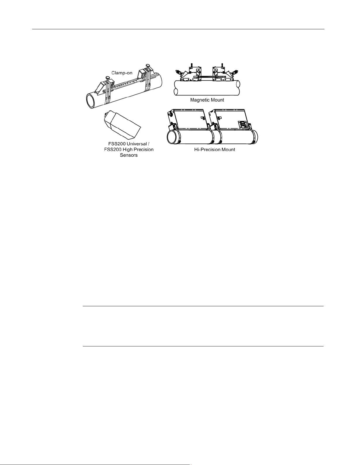
1.5 Required Tools
Figure 1-1 Mounting frames
It is helpful to have common electric and hand tools available for installation of the sensors.
● For easy programming, a PC would also be helpful and can be used later for diagnostics
and documentation.
● Sensor cables are normally preassembled at the transmitter end.
● Hot-air gun if shrink sleeves are needed.
● A plastic hammer and bubble level should be used for sensor mounting and Vernier
adjustment of sensor frames.
● For preparing irregular pipe surfaces that have old paint, corrosion, etc. an electric hand
sander may be used.
● An optional circumference tape measure for pipe and sensor installation.
● Use a thickness gauge to measure pipe wall thickness. If not available use pipe class
tables or call technical support.
● Assorted sizes of screwdrivers, nut drivers and wrenches.
FSS200 clamp-on sensors
Installation Manual, 08/2017, A5E36255466-AC
9
Introduction
Optional mounting compounds
1.6
Checking the consignment
WARNING
Using a damaged or incomplete device
1.7
Security information
1.6 Checking the consignment
● P/N 7ME39600UC40 Dry couplant pads (Liquid installation only)
● P/N 7ME 39600UC20 Super Lube
● P/N 7ME39600UC32 Krytox GPL207
1. Check the packaging and the delivered items for visible damage.
2. Report any claims for damages immediately to the shipping company.
3. Retain damaged parts for clarification.
4. Check the scope of delivery by comparing your order to the shipping documents for
correctness and completeness.
Risk of explosion in hazardous areas. May cause death or serious injury.
• Do not use damaged or incomplete devices.
Siemens provides products and solutions with industrial security functions that support the
secure operation of plants, systems, machines and networks.
In order to protect plants, systems, machines and networks against cyber threats, it is
necessary to implement – and continuously maintain – a holistic, state-of-the-art industrial
security concept. Siemens’ products and solutions only form one element of such a concept.
Customer is responsible to prevent unauthorized access to its plants, systems, machines
and networks. Systems, machines and components should only be connected to the
enterprise network or the internet if and to the extent necessary and with appropriate security
measures (e.g. use of firewalls and network segmentation) in place.
Additionally, Siemens’ guidance on appropriate security measures should be taken into
account. For more information about industrial security, please visit:
http://www.siemens.com/industrialsecurity
Siemens’ products and solutions undergo continuous development to make them more
secure. Siemens strongly recommends to apply product updates as soon as available and to
always use the latest product versions. Use of product versions that are no longer supported,
and failure to apply latest updates may increase customer’s exposure to cyber threats.
To stay informed about product updates, subscribe to the Siemens Industrial Security RSS
Feed under:
http://www.siemens.com/industrialsecurity
FSS200 clamp-on sensors
10 Installation Manual, 08/2017, A5E36255466-AC
2
2.1
Precondition for safe use
Symbol
Explanation
2.1.1
Improper device modifications
WARNING
Improper device modifications
2.2
Laws and directives
This device left the factory in good working condition. In order to maintain this status and to
ensure safe operation of the device, observe these instructions and all the specifications
relevant to safety.
Observe the information and symbols on the device. Do not remove any information or
symbols from the device. Always keep the information and symbols in a completely legible
state.
Consult operating instructions
Risk of explosion in hazardous areas. May cause death or serious injury
Risk to personnel, system and environment can result from modifications to the device,
particularly in hazardous areas.
• Only carry out modifications that are described in the instructions for the device. Failure
to observe this requirement cancels the manufacturer's warranty and the product
approvals.
FSS200 clamp-on sensors
Installation Manual, 08/2017, A5E36255466-AC
Observe the safety rules, provisions and laws applicable in your country during connection,
assembly and operation. These include, for example:
● National Electrical Code (NEC - NFPA 70) (USA)
● Canadian Electrical Code (CEC) (Canada)
11

Safety notes
2.2.1
FCC Conformity
US Installations only: Federal Communications Commission (FCC) rules
Note
•
•
2.2.2
Conformity with European directives
Electromagnetic
compatibility EMC
2014/30/EU
Directive of the European Parliament and of the Council on the ha
nisation of the laws of the Member States relating to electroma
compatibility
Low voltage d
rect
2014/35/EU
Directive of the Eu
nisation of the laws of the Member States relating to the making avail
b
in certain
voltage limits
Atmosphère expl
sible ATEX
2014/34/EU
Directive of the European Parliament and the Council on the harm
ation of the laws of the Member States relating to equipment and prote
tive systems intended for use in potentially explosive atmospheres
PED
2014/53/EU
Directive of the European Parliam
nisation of the laws of the Member States relating to the making avail
ble on the market of radio equipment and repealing Directive 1999/5/EC
2.2 Laws and directives
Further provisions for hazardous area applications are for example:
● IEC 60079-14 (international)
● EN 60079-14 (EC)
This equipment has been tested and found to comply with the limits for a Class A digital
device, pursuant to Part 15 of the FCC Rules. These limits are designed to provide
reasonable protection against harmful interference when the equipment is operated in a
commercial environment.
This equipment generates, uses, and can radiate radio frequency energy and, if not
installed and used in accordance with the operating instructions, may cause harmful
interference to radio communications. Operation of this equipment in a residential area is
likely to cause harmful interference to radio communications, in which case the user will
be required to correct the interference at his own expense.
The CE marking on the device symbolizes the conformity with the following European
directives:
rmo-
gnetic
i-
ive LVD
The applicable directives can be found in the EC conformity declaration of the specific
device.
FSS200 clamp-on sensors
12 Installation Manual, 08/2017, A5E36255466-AC
● RoHS directive
le on the market of electrical equipment designed for use with
o-
ropean Parliament and of the Council on the harmo-
a-
onis
c-
ent and of the Council on the harmo-
a-

Safety notes
Note
CE declaration
The CE declaration certificate is available on the SensorFlash SD card delivered with the
device.
2.3
Use in hazardous locations
Qualified personnel for hazardous area applications
2.3.1
Unsuitable device for the hazardous area
WARNING
Use in hazardous areas
2.3 Use in hazardous locations
Persons who install, connect, commission, operate, and service the device in a hazardous
area must have the following specific qualifications:
● They are authorized, trained or instructed in operating and maintaining devices and
systems according to the safety regulations for electrical circuits, high pressures,
aggressive, and hazardous media.
● They are authorized, trained, or instructed in carrying out work on electrical circuits for
hazardous systems.
● They are trained or instructed in maintenance and use of appropriate safety equipment
according to the pertinent safety regulations.
Risk of explosion in hazardous areas. May cause death or serious injury.
• Only use equipment that is approved for use in the intended hazardous area and
labeled accordingly.
FSS200 clamp-on sensors
Installation Manual, 08/2017, A5E36255466-AC
13
Safety notes
2.3.2
Loss of safety of device with type of protection "Intrinsic safety Ex i"
WARNING
Loss of safety of device with type of protection "Intrinsic safety Ex i"
2.3.3
Special conditions for safe use
Special conditions for safe use
WARNING
Laying of cables
2.3 Use in hazardous locations
Risk of explosion May cause death or serious injury.
If the device has already been operated in non-intrinsically safe circuits or the electrical
specifications have not been observed, the safety of the device is no longer ensured for use
in hazardous areas. There is a risk of explosion.
• Connect the device with type of protection "Intrinsic safety" solely to an intrinsically safe
circuit.
• Observe the specifications for the electrical data on the certificate and/or in Technical
data (Page 81).
In general, it is required that:
● The terminal space may be opened when an explosive gas or dust atmosphere may be
present at any time. Access power terminals by lifting the cover only when de-energized.
● Appropriate cable connectors are used.
● Substitution of components may impair Intrinsic Safety.
● Sensor and transmitter are connected to the potential equalization throughout the
hazardous area.
● EN/IEC 60079-14 is considered for installation in hazardous areas.
Must be installed in accordance with Siemens control drawing A5E42071597A.
Risk of explosion in hazardous areas. May cause death or serious injury.
Cable for use in hazardous areas must satisfy the requirements for having a proof voltage
of at least 500 V AC applied between the conductor/ground, conductor/shield and
shield/ground.
Connect the devices that are operated in hazardous areas as per the stipulations applicable
in the country of operation.
FSS200 clamp-on sensors
14 Installation Manual, 08/2017, A5E36255466-AC
Safety notes
WARNING
Field wiring installation
2.4
Installation in hazardous areas
WARNING
Equipment used in hazardous areas
Note
Important
The FST220 flowmeter is not suitable for use in hazardous areas.
Hazardous area approvals
Device
Gas
Dust
FST030 transmitter
Zone 2
Zone 22
FSS200 sensor
Zone 0
Zone 20/21
FST020 transmitter
N/A
N/A
FM approval
Transmitter
2.4 Installation in hazardous areas
Risk of explosion in hazardous areas. May cause death or serious injury.
Ensure that the national requirements of the country in which the devices are installed are
met.
Risk of explosion in hazardous areas. Death or serious injury may occur.
Equipment used in hazardous areas must be Ex-approved for the region of installation and
marked accordingly. It is required that the special conditions for safe use provided in the
manual and in the Ex certificate are followed!
The device is approved for use in hazardous area according to the lists below. Special
conditions for safe installation and operation specified by each approval authority are
included in the relevant certificate.
Table 2- 1 ATEX approval
Transmitter FST030
Class I Division 2 Groups A,B,C,D T*
Class II Division 2 Groups E,F,G
FSS200 clamp-on sensors
Installation Manual, 08/2017, A5E36255466-AC
15

Safety notes
Sensor
Note
Control drawing
* See Control drawing A5E37305975A
Installation variations
Note
Requirements for safe installation
•
•
Note
FST020 is not suitable for hazardous locations.
2.4 Installation in hazardous areas
Class III Division 1
Class I Zone 2 and Zone 22
Transmitter FST020
Not for hazardous areas
Class I+II+III Division 1 Groups A, B, C, D, E, F, G.
Class I Zone 0, Zone 20/21
The sensors can be installed in Zone 0, Div. 1 as Intrinsically Safe.
Standard remote installation with FST030 because the connection is certified Intrinsically
Safe.
FSS200 clamp-on sensors
16 Installation Manual, 08/2017, A5E36255466-AC
3
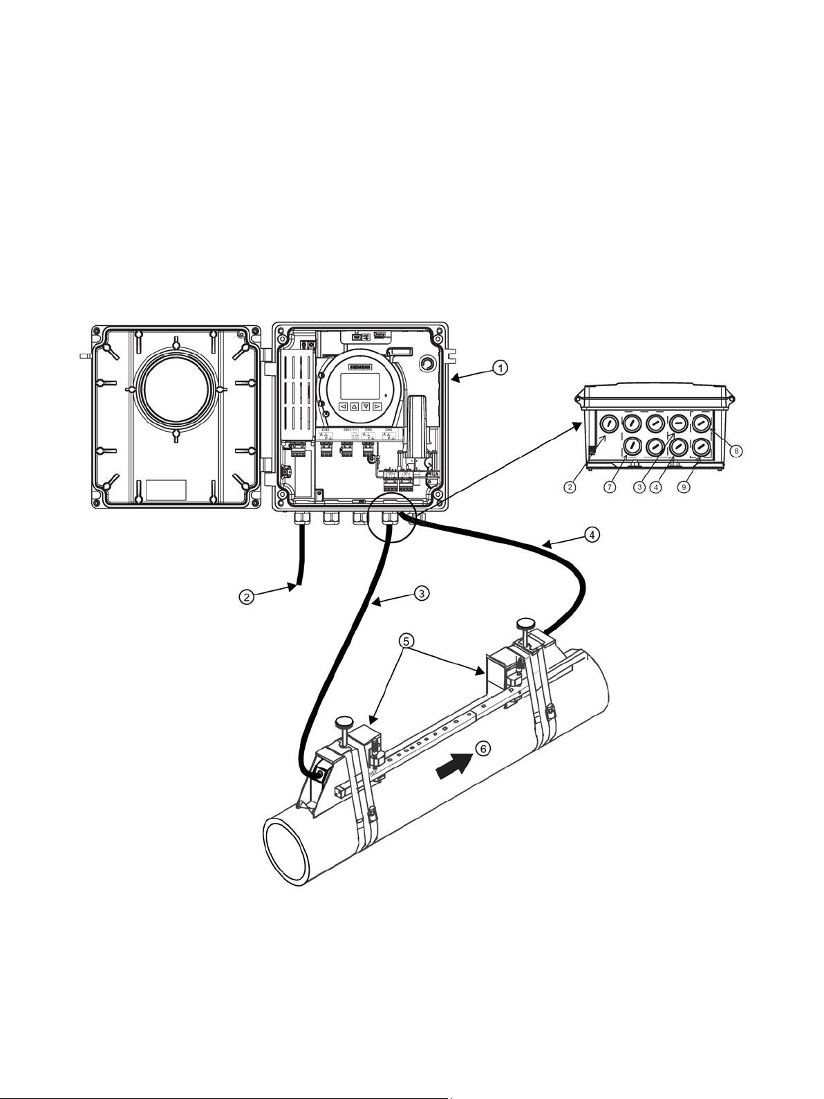
FST030 system
①
FST030 wall mounted transmitter
⑤
Sensors
②
Power cable
⑥
Flow direction
③
Upstream sensor cable (1A) Path 1
⑦
Ports for I/O, Communications, RTDs
④
Downstream sensor cable (1B) Path 1
⑧
Path 2 - Upstream (2A)
⑨ Path 2 - Downstream (1B)
The illustration below shows a typical transmitter and clamp-on sensor flowmeter
configuration.
FSS200 clamp-on sensors
Installation Manual, 08/2017, A5E36255466-AC
17
Installation overview
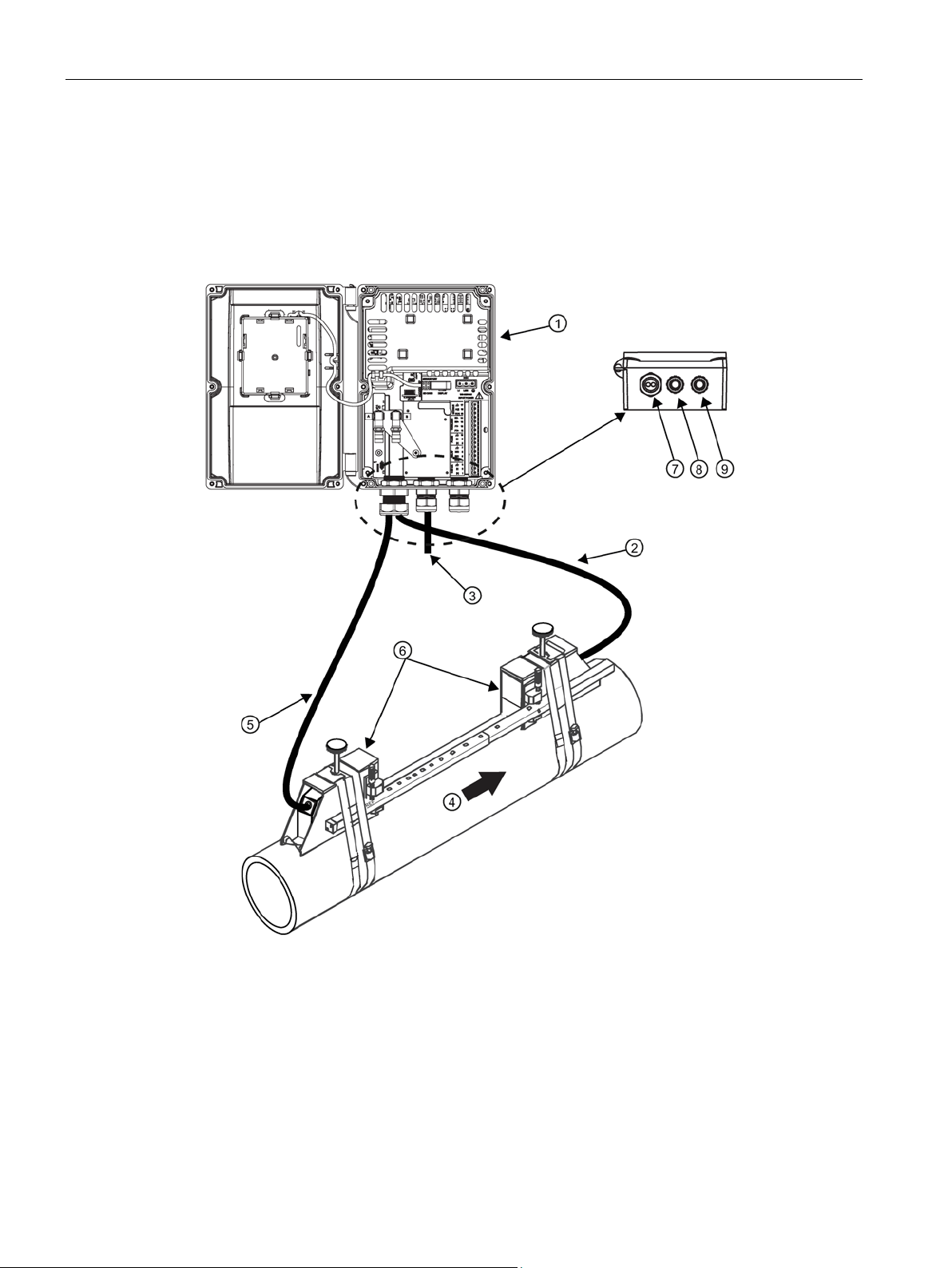
FST020 system
①
FST020 wall mounted transmitter
⑤
Upstream sensor cable (1A) Path 1
②
Downstream sensor cable (1B) Path 1
⑥
Sensors
③
Power cable
⑦
Sensor ports
④
Flow direction
⑧
Input power
⑨ I/O port
Figure 3-1 Wall mount transmitter overview (Reflect mount)
The illustration below shows a typical transmitter and clamp-on sensor flowmeter
configuration.
Figure 3-2 Wall mount transmitter overview (Reflect mount)
FSS200 clamp-on sensors
18 Installation Manual, 08/2017, A5E36255466-AC

Installation overview
3.1
System configuration
Transmitter
Sensor type
Temperature range
FSS200 Hi Precision - T1
-40°C to +65°C (-40°F - +149°F)
FSS200 Universal
-40°C to +120°C (-40°F - +248°F)
FSS200 High Temperature
-40°C to +230°C (-40°F to +446°F)
3.1 System configuration
Generally after deciding on the necessary flow measurements an evaluation should be done.
In this way, the best economical solution can be obtained since configurations and accuracy
measurement requirements can be in conflict with the overall system costs. In particular
when using Clamp-on systems it’s important to perform a very detailed evaluation. Later this
will result in smooth installations and the highest customer satisfaction.
For example, a poor accuracy may result if the installed pipe size is different than actual pipe
size. Although operation may still be achieved, accuracy can be compromised due to
incorrect volume calculation.
The SITRANS F US ultrasonic flowmeter systems consist of a transmitter, one or two sensor
pairs and the connecting cables. The following table lists process temperatures for the
available combinations of sensors and transmitters.
FST030
FST020
FSS200 Hi Precision - T2 0°C to +120°C (32°F - +248°F)
FSS200 clamp-on sensors
Installation Manual, 08/2017, A5E36255466-AC
19

Installation overview
3.1 System configuration
FSS200 clamp-on sensors
20 Installation Manual, 08/2017, A5E36255466-AC

4
Note
IMPORTANT
This step should have been done prior to ordering the clamp
4.1
Environment
Process medium temperature
Aggressive atmospheres
This chapter describes how to install the sensors. The following installation steps must be
carried out:
● Determine a suitable installation location for the sensors and transmitter. See
Determining a location (Page 23).
-on system
● Collect all relevant fluid and pipe data (pipe material and dimensions, fluid type or
approximate sound speed, viscosity, etc.).
● Install and apply power to the transmitter, then follow the sensor setup wizard to
determine the recommended sensor orientation and spacing. See Orienting the sensors
(Page 26)
● Install the sensors using the supplied mounting hardware. See Mounting the sensors
(Page 22)
● Connect the sensor cables.
● Complete the sensor setup wizard to begin measuring flow. See Installation instructions
(Page 27)
SITRANS F flowmeters with minimum IP66/IP67/NEMA 4X enclosure rating are suitable for
indoor and outdoor installations.
If applicable, make sure that specifications for rated medium temperature (TS) plus ambient
temperature that are indicated on the device nameplate / label will not be exceeded.
Ensure that the device is suitable for the application and that it is installed where there is no
risk of penetration of aggressive vapors.
FSS200 clamp-on sensors
Installation Manual, 08/2017, A5E36255466-AC
21

Installing/mounting
Direct sunlight
WARNING
Installation in hazardous location
4.2
Installation safety precautions
Note
Material compatibility
Siemens can provide you with support concerning selection of sensors. However, you are
responisible for the selection of components. Siemens accepts no liability for faults or
failures resulting from incompatible materials.
4.3
Sensor installation parameters
Pipe data:
Process conditions:
4.2 Installation safety precautions
Prevent the device from overheating or materials becoming brittle due to UV exposure by
protecting it from direct sunlight. Make sure that the maximum permissible ambient
temperature is not exceeded. Refer to the information in Technical data (Page 81).
Risk of explosion in hazardous areas
Special requirements apply to the location and installation of the device. See Installation in
hazardous areas (Page 15).
Special precautions must be taken when the flowmeter is mounted in applications with
working pressures/media that can be dangerous to people, surroundings, equipment or
others in case of pipe fracture.
● Take appropriate protective measures to avoid contact with surfaces with temperatures
above 70 °C (155 °F).
● Prevent severe external stresses and loads from acting on the device.
● Do not install the flowmeter in the vicinity of strong electromagnetic fields, for example
near motors, variable frequency drives, transformers etc.
The following parameters are required for a correct sensor installation, ensuring the best
possible flow measurement accuracy:
●
applicable), pipe roughness, upstream and downstrream straight run (in pipe diameters).
material, outer diameter, wall thickness, Liner material and thickness (if
●
viscosity, positive flow direction.
FSS200 clamp-on sensors
22 Installation Manual, 08/2017, A5E36255466-AC
Type of fluid, fluid sound speed (if known), process temperature, fluid
Installing/mounting
Sensor data:
Environment conditions:
4.4
Determining a location
Introduction
Hardware considerations
Transmitter:
Sensor:
Mounting:
Sensor cables:
Typical sensor locations
Note
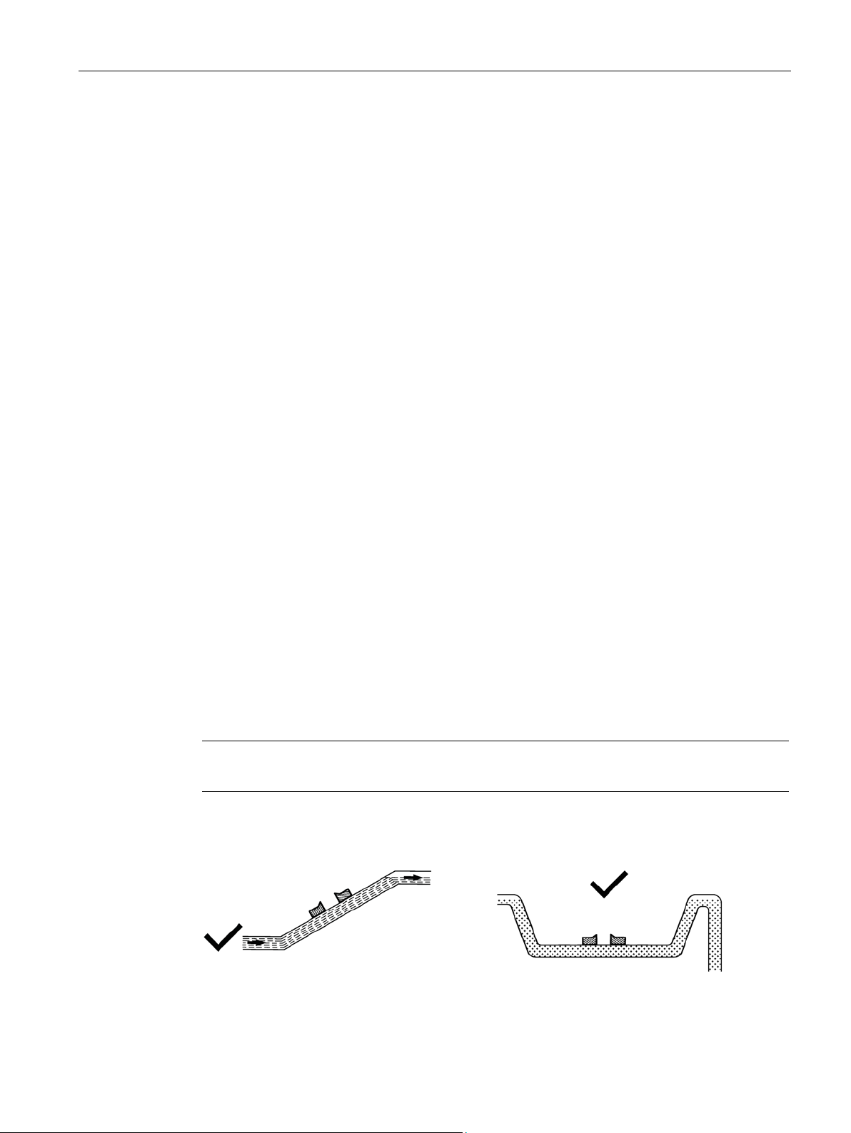
The pipe should always be completely filled with liquid.
4.4 Determining a location
●
●
cable lengths, temperature, sun protection/rain, protection against dirt, vibrations,
corrosion, easy access for maintenance: ladder or scaffolding, below ground or
submersible.
Sensor type and size (indicated on label), length of sensor cable pair.
Mounting location transmitter/sensors, distance and required
There are a number of factors to consider when deciding on an installation location for the
clamp-on sensors and transmitter. Primarily, the pipe section should remain completely full
during normal operation and be in reasonable condition, without excessive corrosion (or
scaling) which can interfere with ultrasound transmission into the fluid. Available straight pipe
run and installation in hazardous areas are also important points to consider when selecting
a location.
The following hardware characteristics need to be considered:
●
maximum allowed sensor cable length. (Refer to appropriate transmitter Operating
Instructions manual for details.)
●
material and dimensions.
●
●
● Locate the sensors in U-shaped pipes if pipes are only partially filled or have free outlet.
Ingress protection rating, Hazardous area rating, ambient temperature range,
Ingress protection rating, Operating temperature range, compatibility with pipe
Corrosion resistance, vibration tolerance, direct burial, submersibility.
Ingree protection rating, temperature rating, electromagnetic compatibility.
FSS200 clamp-on sensors
Installation Manual, 08/2017, A5E36255466-AC
23
Installing/mounting
Selecting a location for the sensors
4.4 Determining a location
● Avoid, if possible, the following installations:
– Installation at the highest point of the pipe system
– Installation in vertical pipes with free outlet or downwards flow
1. Locate the sensors downstream from the center of the longest available straight run. A
location ten pipe diameters or greater downstream from the nearest bend will provide
adequate flow profile conditions.
2. Do not, if possible, install the sensors downstream from a throttling valve, a mixing tank,
the discharge of a positive displacement pump or any other equipment that could possibly
aerate the liquid. The best location will be as free as possible from flow disturbances,
vibration, sources of heat, noise, or radiated energy.
3. Avoid mounting the sensors on a section of pipe with any external scale. Remove all
scale, rust, loose paint, etc., from the location.
4. Do not mount the sensors on a surface aberration (pipe seam, etc.)
FSS200 clamp-on sensors
24 Installation Manual, 08/2017, A5E36255466-AC
Installing/mounting
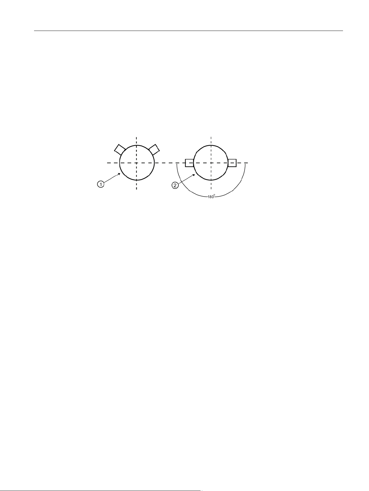
Avoid mounting sensors on the top or bottom of a horizontal pipe
①
Dual path, Reflect mount
②
Dual path, Direct mount
Transmitter mounting
Sensor mounting preparation
4.4 Determining a location
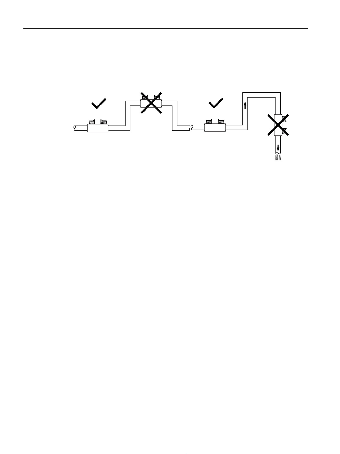
5. Do not mount sensors from different ultrasonic flowmeters on the same pipe. Also, do not
run the sensor cables in common bundles with cables from other instrumentation. You
can run these cables through a common conduit ONLY if they originate at the same
flowmeter.
6.
a horizontal pipe is either the ten o’clock and two o’clock position for Reflect mode, or one
sensor at nine o’clock and one sensor at three o’clock for Direct Mode. Mounting on a
vertical pipe is recommended only if flow is in the upward direction. When mounting on a
vertical pipe flowing in a downward direction make sure there is sufficient back pressure
in the system to maintain a full pipe.
. The best placement on
Figure 4-1 Sensor alignment (horizontal plane)
Refer to the transmitter Operating Instructions for transmitter mounting.
The transmitter independently calculates the best distance for the sensors on the pipe
according to the selected parameters. A manual search for the best signal strength and
signal quality is not necessary. To receive these calculations, certain parameters have to be
programmed into the meter:
● Pipe outer diameter (e.g. selection by inside table > metric DIN100 -> 114.3 mm)
● Pipe wall thickness (DIN automatically 3.6 mm or by manual input)
● Pipe material - Steel or other materials from material tables
● Liner inside - (e.g. Cement - 5 mm)
● Medium settings - Liquid Class (Water 20°C or other kind of liquid by table or custom
setting)
● Pipe Up- and Downstream conditions (only required if condition is not ideal)
● Sensor type - Sensor model (e.g. FSS200 Universal)
FSS200 clamp-on sensors
Installation Manual, 08/2017, A5E36255466-AC
● Sensor size (e.g. C3 - see Sensor nameplate (Page 47))
● Automatic calculating for mounting and sensor distance (i.e. how many reflections,
nominal distance, mounting frame index number (e.g. 16).
25
Installing/mounting
4.5
Orienting the sensors
Flow direction
Orienting the sensors
Note
IMPORTANT
Avoid installing sensors on top or on the bottom of a horizantal pipe.
4.5 Orienting the sensors
There are no flow direction symbols shown in the sensors. Positive flow is defined as the
movement of fluid from the upstream "A" sensor to the downstream "B" sensor, whereas
negative flow is in the reverse direction.
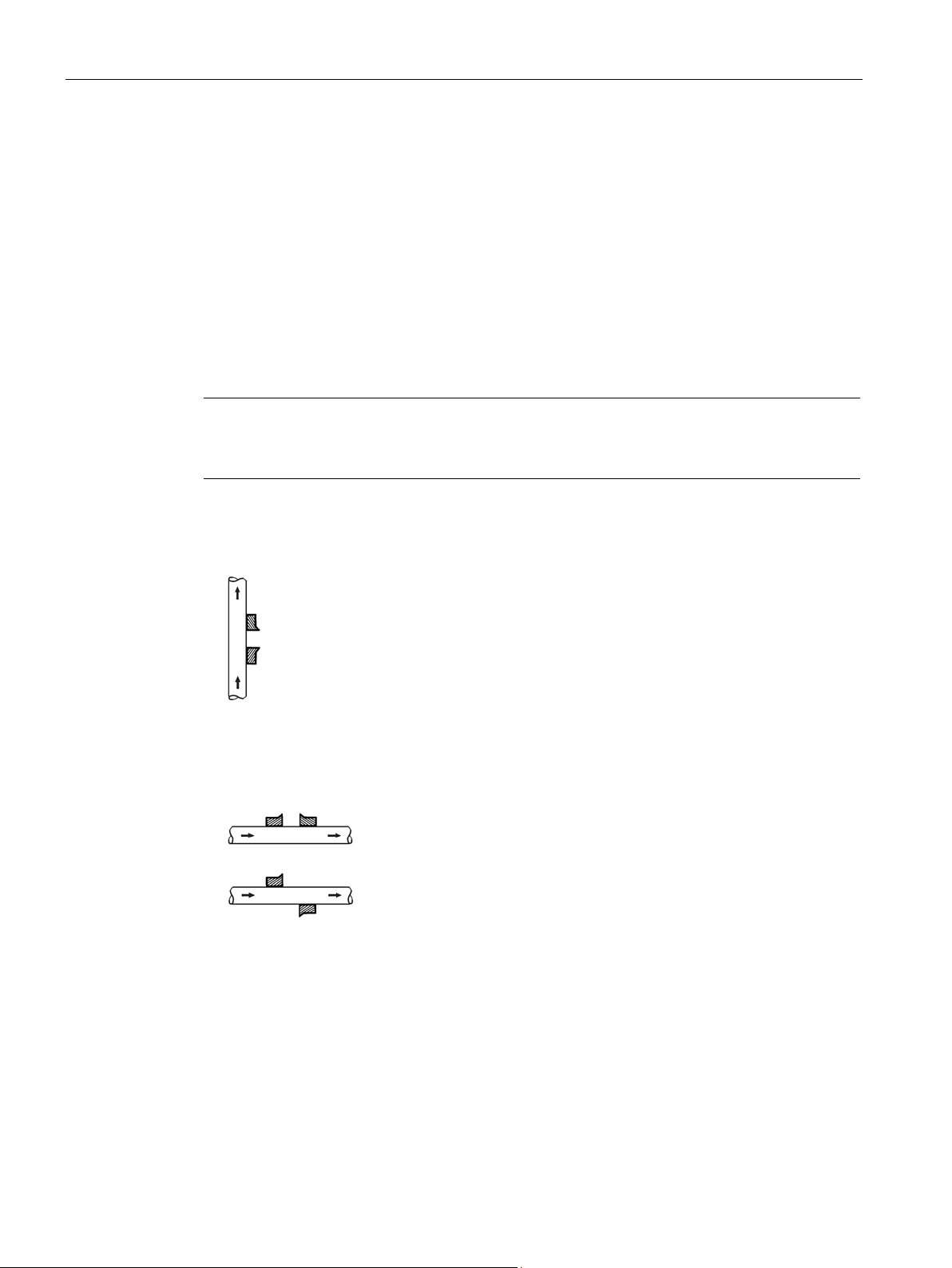
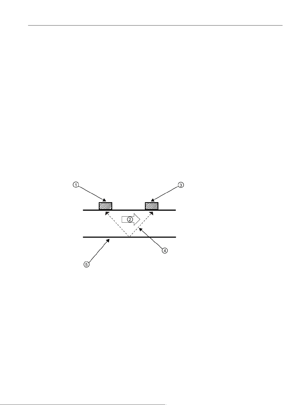
Siemens recommends orienting the sensors in one of the following ways:
1. Vertical orientation with an upwards flow in order to minimize the effect of gas / air
bubbles in the media (sensors shown in Reflect Mount).
Figure 4-2 Vertical installation with an upwards flow
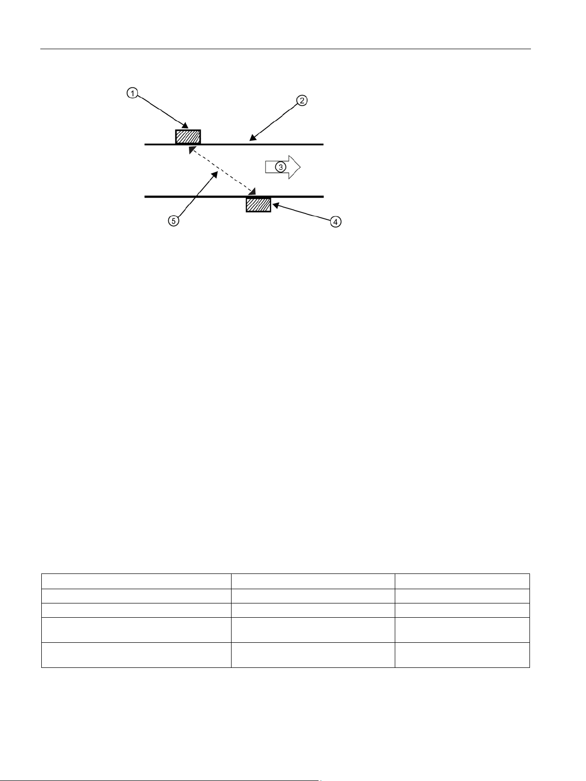
2. Horizontal orientation with sensors shown in Reflect Mount and Direct mount. Note that
flow can move in either direction.
FSS200 clamp-on sensors
26 Installation Manual, 08/2017, A5E36255466-AC
Installing/mounting
4.6
Installation instructions
4.6.1
Preliminary installation procedures
Introduction
Clamp-on sensor mounting modes
①
Upstream sensor
④
Sonic path
②
Flow direction
⑤
Pipe
③
Downstream sensor
4.6 Installation instructions
To install the sensors these basic steps must be followed:
1. Program parameters into transmitter
2. Mount the sensors on pipe using parameters from transmitter
3. Connect sensor cables from sensor to transmitter
All though the transmitter recommends a mounting mode after analyzing your pipe and liquid
data entries you can still install clamp-on sensors in the way that best suits your application
and the sensor type you have purchased.
FSS200 clamp-on sensors
Installation Manual, 08/2017, A5E36255466-AC
Figure 4-3 Reflect mount (Pipe shown from above in 12 o'clock position)
Reflect mount is recommended whenever possible. This is the simplest way to mount the
sensors. Also, Reflect mount resists abnormal flow profile conditions such as cross-flow
within the flow stream. In addition, Reflect mount may be the only possibility if conditions do
not allow access to the opposite side of the pipe.
Direct mount provides a shorter sonic beam path. This usually improves performance with
sonically attenuative liquids or pipe materials. Direct mount is recommended for plastic
pipes. Compared to Direct mounting, Reflect mount requires almost double the amount of
mounting length. Therefore, Direct mount may be the only option if the availability of
mounting space is limited.
27
Installing/mounting
①
Upstream sensor
④
Downstream sensor
②
Pipe
⑤
Sonic path
③
Flow direction
Mounting supplies
Mounting strap kits
Mounting strap kits
Pipe diameter
SAE band sizes (Qty.)
7ME396000SM00
50.8 mm (2-inch) to 177.8 mm (7-inch)
#88 (2) #128 (2)
7ME396000SM10
50.8 mm (2-inch) to 330.2 mm (13-inch)
#88 (2) #152 (2)
inch)
inch)
4.6 Installation instructions
Figure 4-4 Direct mount (Pipe shown from above in 12 o'clock position)
The following items will be needed to mount the sensors (most materials are supplied):
● Flat blade screwdriver
● Mounting frames or mounting tracks
● Tape, chalk and a ruler or measuring tape
● Mounting straps
● Spacer bar
● Mounting guide (for Direct mount)
● Ultrasonic coupling compound and/or coupling pads
● Sensors (matched set)
The available mounting strap kits are listed below. Each kit comes with up to two band sizes
to cover its designated pipe diameter range and a spacing guide for Direct mount. In most
cases, the kits come with the mounting hardware.
7ME396000SM20 330.2 mm (13-inch) to 609.6 mm (24-
7ME396000SM30 609.6 mm (24-inch) to 1219.2 mm (48-
FSS200 clamp-on sensors
28 Installation Manual, 08/2017, A5E36255466-AC
#188 (2) #280 (2)
#152 (4) #312 (4)
 Loading...