

Siemens SITRANS FS230 Operating Instructions Manual

Compact Operating Instructions
Answers for industry.
02/2017
Edition
Ultrasonic Flowmeters
SITRANS FS230
SITRANS F

English ······························································································ 1
Deutsch ·························································································· 28
Español ··························································································· 55
Français ·························································································· 81
Italiano ····························································································108
Nederlands ·····················································································134

© Siemens AG 2017. All rights reserved
A5E38755607-AA, 02/2017
1
SITRANS F
Ultrasonic Flowmeters
SITRANS FS230
Compact Operating Instructions
Legal information
Warning notice system
This manual contains notices you have to observe in order to ensure your personal safety, as well as to prevent damage to property. The
notices referring to your personal safety are highlighted in the manual by a safety alert symbol, notices referring only to property damage
have no safety alert symbol. These notices shown below are graded according to the degree of danger.
DANGER
indicates that death or severe personal injury will result if proper precautions are not taken.
WARNING
indicates that death or severe personal injury may result if proper precautions are not taken.
CAUTION
indicates that minor personal injury can result if proper precautions are not taken.
NOTICE
indicates that property damage can result if proper precautions are not taken.
If more than one degree of danger is present, the warning notice representing the highest degree of danger will be used. A notice warning of
injury to persons with a safety alert symbol may also include a warning relating to property damage.
Qualified Personnel
The product/system described in this documentation may be operated only by
personnel qualified
for the specific task in accordance with
the relevant documentation, in particular its warning notices and safety instructions. Qualified personnel are those who, based on their
training and experience, are capable of identifying risks and avoiding potential hazards when working with these products/systems.
Proper use of Siemens products
Note the following:
WARNING
Siemens products may only be used for the applications described in the catalog and in the relevant technical documentation. If products
and components from other manufacturers are used, these must be recommended or approved by Siemens. Proper transport, storage,
installation, assembly, commissioning, operation and maintenance are required to ensure that the products operate safely and without any
problems. The permissible ambient conditions must be complied with. The information in the relevant documentation must be observed.
SITRANS FS230
2 A5E38755607-AA, 02/2017
1
Introduction
1.1
Purpose of the documentation
This document contains all essential health and safety information required for safe use of the device.
Before installation and commissioning of the device, the operating instructions on the electronic data medium must be read
carefully.
1.2
Revision history
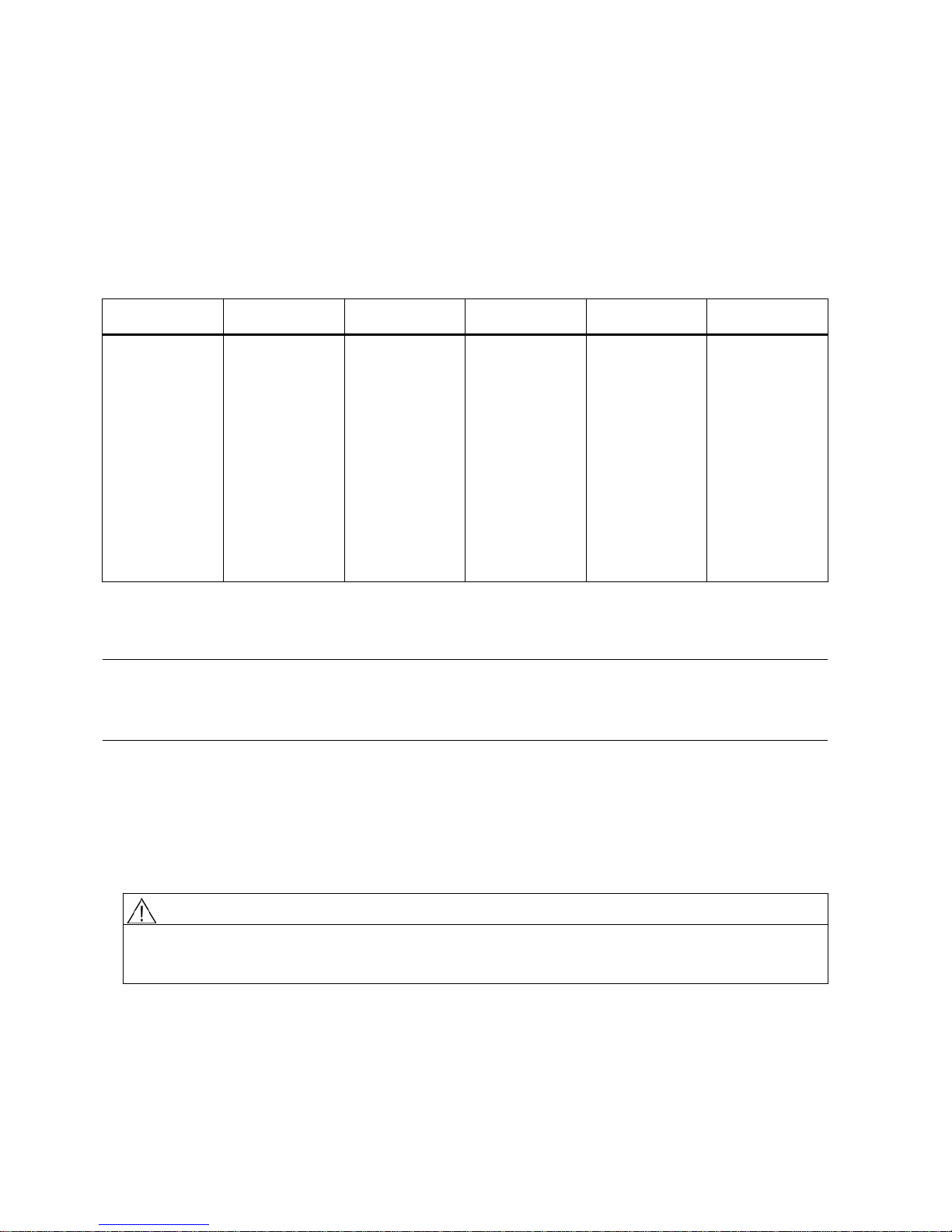
The following table shows major changes in the documentation compared to the previous edition.
Edition
Remarks
FW version
HW version
EDD version
HART device
revision
02/2017
• First edition
1.00.00 01
• SIMATIC PDM
driver for
HART 1.00.00
• SIMATIC PDM
driver for
Modbus
1.00.00
• AMS driver for
HART 1.00.00
• FC475 driver
for HART
1,00.00
• DTM/FDT
driver for
HART 1.00.00
1
1.3
Designated use
Use the device to measure process medium in accordance with the information in the operating instructions.
Note
Use in a domestic environment
This Class A Group 1 equipment is intended for use in industrial areas.
In a domestic environment this device may cause radio interference.
1.4
Checking the consignment
1. Check the packaging and the delivered items for visible damage.
2. Report any claims for damages immediately to the shipping company.
3. Retain damaged parts for clarification.
4. Check the scope of delivery by comparing your order to the shipping documents for correctness and completeness.
WARNING
Using a damaged or incomplete device
Risk of explosion in hazardous areas.
•
Do not use damaged or incomplete devices.

SITRANS FS230
A5E38755607-AA, 02/2017
3
1.5
Security information
Siemens provides products and solutions with industrial security functions that support the secure operation of plants,
systems, machines, and networks.
In order to protect plants, systems, machines and networks against cyber threats, it is necessary to implement – and
continuously maintain – a holistic, state-of-the-art industrial security concept. Siemens’ products and solutions only form one
element of such a concept.
Customer is responsible to prevent unauthorized access to its plants, systems, machines and networks. Systems, machines
and components should only be connected to the enterprise network or the internet if and to the extent necessary and with
appropriate security measures (e.g. use of firewalls and network segmentation) in place.
Additionally, Siemens’ guidance on appropriate security measures should be taken into account. You can find more
information about industrial security by visiting:
http://www.siemens.com/industrialsecurity
.
Siemens’ products and solutions undergo continuous development to make them more secure. Siemens strongly
recommends to apply product updates as soon as available and to always use the latest product versions. Use of product
versions that are no longer supported, and failure to apply latest updates may increase customer’s exposure to cyber
threats.
To stay informed about product updates, subscribe to the Siemens Industrial Security RSS Feed under
http://www.siemens.com/industrialsecurity
.
1.6
Transportation and storage
To guarantee sufficient protection during transport and storage, observe the following:
● Keep the original packaging for subsequent transportation.
● Devices/replacement parts should be returned in their original packaging.
● If the original packaging is no longer available, ensure that all shipments are properly packaged to provide sufficient
protection during transport. Siemens cannot assume liability for any costs associated with transportation damages.
NOTICE
Insufficient protection during storage
The packaging only provides limited protection against moisture and infiltration.
• Provide additional packaging as necessary.
Special conditions for storage and transportation of the device are listed in Technical data (Page 21).
1.7
Notes on warranty
The contents of this manual shall not become part of or modify any prior or existing agreement, commitment or legal
relationship. The sales contract contains all obligations on the part of Siemens as well as the complete and solely applicable
warranty conditions. Any statements regarding device versions described in the manual do not create new warranties or
modify the existing warranty.
The content reflects the technical status at the time of publishing. Siemens reserves the right to make technical changes in
the course of further development.
SITRANS FS230
4 A5E38755607-AA, 02/2017
2
Safety notes
2.1
Preconditions for use
This device left the factory in good working condition. In order to maintain this status and to ensure safe operation of the
device, observe these instructions and all the specifications relevant to safety.
Observe the information and symbols on the device. Do not remove any information or symbols from the device. Always
keep the information and symbols in a completely legible state.
2.1.1
Warning symbols on the device
Symbol
Explanation
Consult operating instructions
2.1.2
SIL note
Note
Functional safety applications (SIL)
If the device is used in a functional safety application, ref
er to the functional safety manual.
2.1.3
Laws and directives
Observe the safety rules, provisions and laws applicable in your country during connection, assembly and operation. These
include, for example:
● National Electrical Code (NEC - NFPA 70) (USA)
● Canadian Electrical Code (CEC) (Canada)
Further provisions for hazardous area applications are for example:
● IEC 60079-14 (international)
● EN 60079-14 (EC)
The CE marking on the device symbolizes the conformity with the following European directives:
Electromagnetic compatibility EMC
2014/30/EU
Directive of the European Parliament and of the Council on the harmonisation of the
laws of the Member S
tates relating to electromagnetic compatibility
Low voltage directive LVD
2014/35/EU
Directive of the European Parliament and of the Council on the harmonisation of the
laws of the Member States relating to the making available on the market of electrical
equipment designed for use within certain voltage limits
Atmosphère explosible ATEX
2014/34/EU
Directive of the European Parliament and the Council on the harmonisation of the
laws of the Member States relating to equipment and protective systems inten
ded for
use in potentially explosive atmospheres
The applicable directives can be found in the EU declaration of conformity of the specific device.
WARNING
Improper device modifications
Risk to personnel, system and environment can result from modifications to the device, particularly in hazardous areas.
• Only carry out modifications that are described in the instructions for the device. Failure to observe this requirement
cancels the manufacturer's warranty and the product approvals.
SITRANS FS230
A5E38755607-AA, 02/2017
5
2.2
Requirements for special applications
Due to the large number of possible applications, each detail of the described device versions for each possible scenario
during commissioning, operation, maintenance or operation in systems cannot be considered in the instructions. If you need
additional information not covered by these instructions, contact your local Siemens office or company representative.
Note
Operation under special ambient conditions
We highly recommend that you contact your Siemens representative or our application department before you operate the
device u
nder special ambient conditions as can be encountered in nuclear power plants or when the device is used for
research and development purposes.
2.3
Use in hazardous areas
Qualified personnel for hazardous area applications
Persons who install, connect, commission, operate, and service the device in a hazardous area must have the following
specific qualifications:
● They are authorized, trained or instructed in operating and maintaining devices and systems according to the safety
regulations for electrical circuits, high pressures, aggressive, and hazardous media.
● They are authorized, trained, or instructed in carrying out work on electrical circuits for hazardous systems.
● They are trained or instructed in maintenance and use of appropriate safety equipment according to the pertinent safety
regulations.
WARNING
Use in hazardous areas
Risk of explosion.
• Only use equipment that is approved for use in the intended hazardous area and labelled accordingly.
WARNING
Loss of safety of device with type of protection "Intrinsic safety Ex i"
If the device has already been operated in non-intrinsically safe circuits or the electrical specifications have not been
observed, the safety of the device is no longer ensured for use in hazardous areas. There is a risk of explosion.
• Connect the device with type of protection "Intrinsic safety" solely to an intrinsically safe circuit.
•
Observe the specifications for the electrical data on the certificate and/or in Technical data (Page 21).
SITRANS FS230
6 A5E38755607-AA, 02/2017
3
Installing/mounting
3.1
Basic safety notes
CAUTION
Hot surfaces resulting from hot process media
Risk of burns resulting from surface temperatures above 70 °C (155 °F).
• Take appropriate protective measures, for example contact protection.
• Make sure that protective measures do not cause the maximum permissible ambient temperature to be exceeded.
Refer to the information in Technical data (Page 21).
WARNING
Exceeded maximum ambient or process media temperature
Danger of explosion in hazardous areas.
Device damage.
• Make sure that the maximum permissible ambient and process media temperatures of the device are not exceeded.
Refer to the information in Technical data (Page 21).
WARNING
Open cable inlet or incorrect cable gland
Danger of explosion in hazardous areas.
• Close the cable inlets for the electrical connections. Only use cable glands or plugs which are approved for the relevant
type of protection.
3.1.1
Installation location requirements
NOTICE
Strong vibrations
Damage to device.
• In plants with strong vibrations, mount the transmitter in a low vibration environment.
CAUTION
Aggressive atmospheres
Damage to device through penetration of aggressive vapors.
•
Ensure that the device is suitable for the application.
CAUTION
Direct sunlight
Device damage.
The device can overheat or materials become brittle due to UV exposure.
• Protect the device from direct sunlight.
• Make sure that the maximum permissible ambient temperature is not exceeded. Refer to the information in Technical
data (Page 21).
SITRANS FS230
A5E38755607-AA, 02/2017
7
Typical system overview
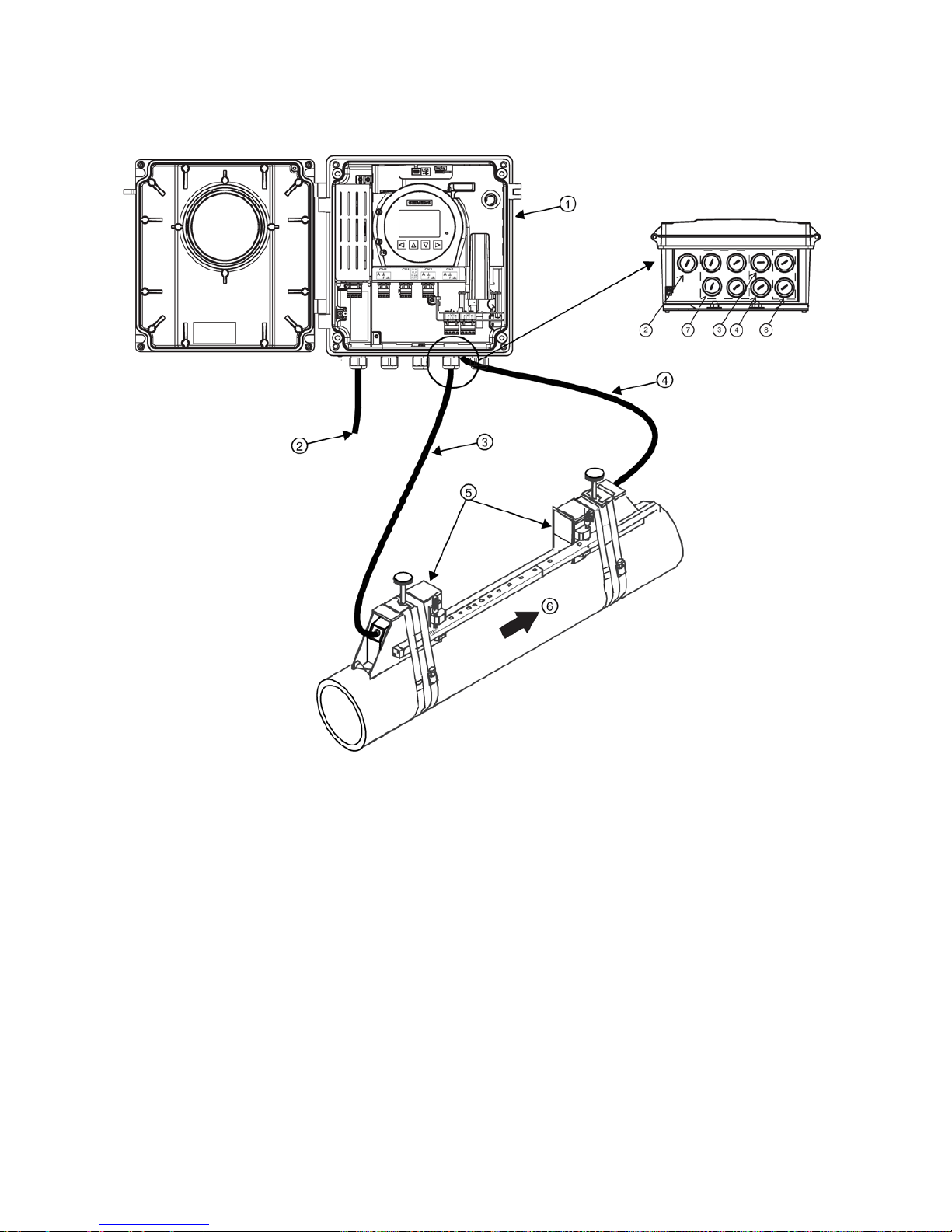
The illustration below shows a typical transmitter and clamp-on sensor flowmeter configuration.
①
FST030 wall mounted transmitter
⑤
Sensors
②
Power cable
⑥
Flow direction
③
Upstream sensor cable (1A) Path 1
⑦
Ports for I/O, Communications, RTDs
④
Downstream sensor cable (1B) Path 1
⑧
Path 2 - Upstream (2A), Downstream (2B). (Ports for
Path 2 sensor cables, if applicable.)
Figure 3-1 Wall mount transmitter overview (Reflect mount)

SITRANS FS230
8 A5E38755607-AA, 02/2017
3.2
Installing sensors in Reflect mount
Reflect mount - Sensor installation using mounting frames and spacer bar
1. Use the Wizard setup procedure to program the meter for application parameters such as pipe size, liquid type, and
sensor size. Once entered the transmitter will return a spacing index number appropriate for the application.
2. Using the supplied space bar, set the distance between the sensors according to the spacing index number provided by
transmitter. The spacing index provides the correct distance apart for the sensors based on the pipe size given.
Before continuing refer to the Reflect mount installation diagram example below.
①
Sensor clamping screw
⑥
Spacer bar pin and reference hole
②
Customer pipe
⑦
Mounting strap
③
7ME39600*** Mounting Frame
⑧
Larger pipes may need additional mounting straps
④
Spring Clip (not present on some mounting frame models) ⑨ Orientation for Single path sensor at the 9 o'clock
position
⑤
Spacer bar
⑩
Orientation for Dual path sensor at the 10 and 2
o'clock positions
Figure 3-2 Reflect mount
3.3
Terminal Layout
Figure 3-3 Terminal layout - wall mount housing
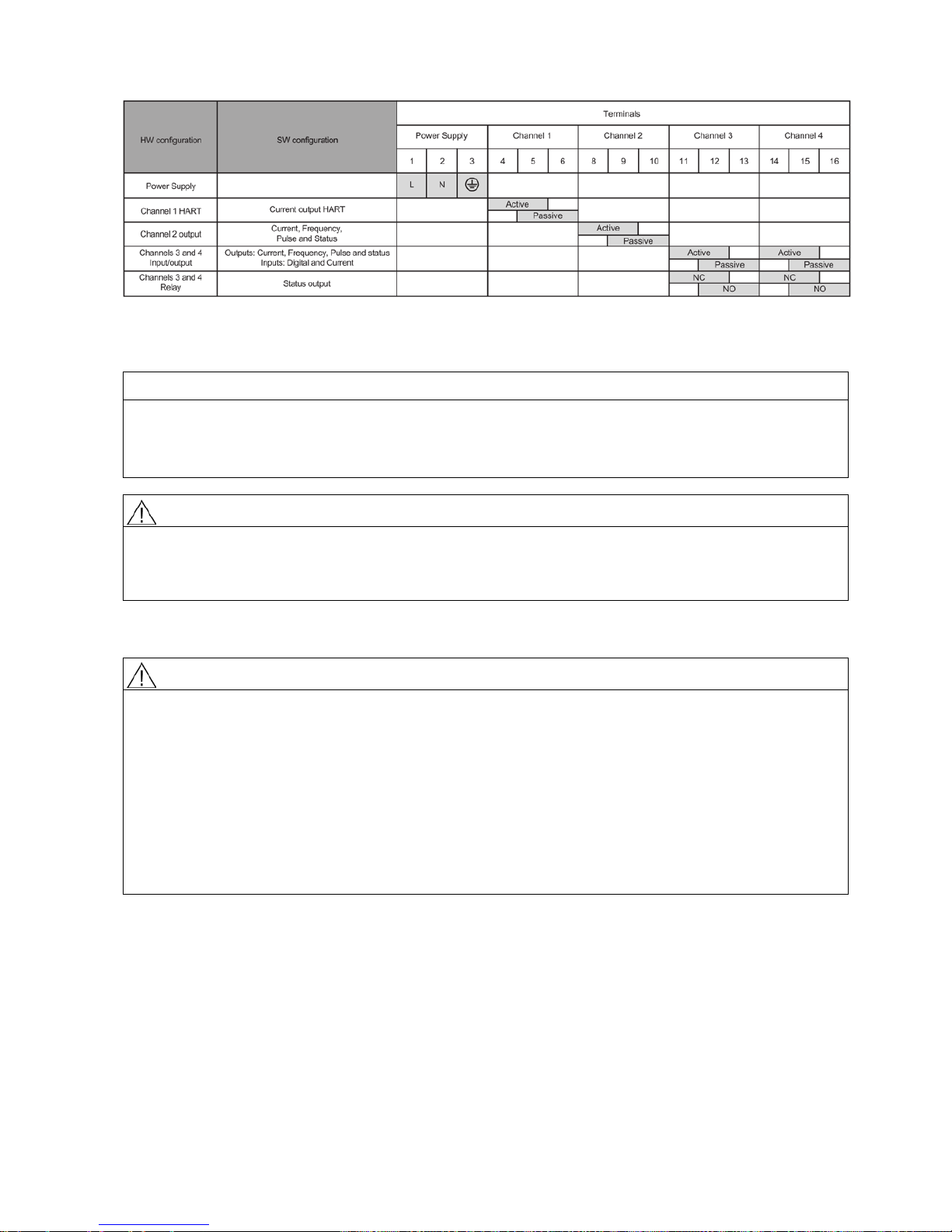
SITRANS FS230
A5E38755607-AA, 02/2017
9
Figure 3-4 Termination/configuration overview (HART)
3.4
Incorrect mounting
NOTICE
Incorrect mounting
The device can be damaged, destroyed, or its functionality impaired through improper mounting.
• Before installing ensure there is no visible damage to the device.
•
Mount the device using suitable tools. See operating instructions.
CAUTION
Loss of type of protection
Damage to device if the enclosure is open or not properly closed. The type of protection specified on the nameplate or in
Technical data (Page 21) is no longer guaranteed.
•
Make sure that the device is securely closed.
3.5
Disassembly
WARNING
Incorrect disassembly
The following risks may result through incorrect disassembly:
- Injury through electric shock
- Risk through emerging media when connected to the process
- Risk of explosion in hazardous area
In order to disassemble correctly, observe the following:
• Before starting work, make sure that you have switched off all physical variables such as pressure, temperature,
electricity etc. or that they have a harmless value.
• If the device contains hazardous media, it must be emptied prior to disassembly. Make sure that no environmentally
hazardous media are released.
•
Secure the remaining connections so that no damage can result if the process is started unintentionally.

SITRANS FS230
10 A5E38755607-AA, 02/2017
4
Connecting
4.1
Basic safety notes
WARNING
Unsuitable cables, cable glands and/or plugs
Risk of explosion in hazardous areas.
• Use only cable glands/plugs that comply with the requirements for the relevant type of protection.
• Tighten the cable glands in accordance with the torques specified in Transmitter (Page 12).
• Close unused cable inlets for the electrical connections.
• When replacing cable glands use only cable glands of the same type.
• After installation check that the cables are seated firmly.
WARNING
Hazardous contact voltage
Risk of electric shock in case of incorrect connection.
• For the electrical connection specifications, refer to the information in Technical data (Page 21).
• At the mounting location of the device observe the applicable directives and laws for installation of electrical power
installations with rated voltages below 1000 V.
NOTICE
Condensation in the device
Damage to device through formation of condensation if the temperature difference between transportation or storage and
the mounting location exceeds 20 °C (36 °F).
•
Before taking the device into operation let the device adapt for several hours in the new environment.
WARNING
Missing PE/ground connection
Risk of electric shock.
Depending on the device version, connect the power supply as follows:
•
Power plug
: Ensure that the used socket has a PE/ground conductor connection. Check that the PE/ground conductor
connection of the socket and power plug match each other.
•
Connecting terminals
: Connect the terminals according to the terminal connection diagram. First connect
the PE/ground
conductor.
NOTICE
Ambient temperature too high
Damage to cable sheath.
• At an ambient temperature ≥ 60 °C (140 °F), use heat-resistant cables suitable for an ambient temperature at least
20 °C (36 °F) higher.
WARNING
Improper power supply
Risk of explosion in hazardous areas as result of incorrect power supply, e.g. using direct current instead of alternating
current.
• Connect the device in accordance with the specified power supply and signal circuits. The relevant specifications can
be found in the certificates, in Technical data (Page 21) or on the nameplate.

SITRANS FS230
A5E38755607-AA, 02/2017
11
WARNING
Lack of equipotential bonding
Risk of explosion through compensating currents or ignition currents through lack of equipotential bonding.
• Ensure that the device is potentially equalized.
Exception
: It may be permissible to omit connection of the equipotential bonding for devices with type of protection
"Intrinsic safety Ex i".
WARNING
Unprotected cable ends
Risk of explosion through unprotected cable ends in hazardous areas.
•
Protect unused cable ends in accordance with IEC/EN 60079-14.
WARNING
Improper laying of shielded cables
Risk of explosion through compensating currents between hazardous area and the non-hazardous area.
• Shielded cables that cross into hazardous areas should be grounded only at one end.
•
If grounding is required at both ends, use an equipotential bonding conductor.
WARNING
Insufficient isolation of intrinsically safe and non-intrinsically safe circuits
Risk of explosion in hazardous areas.
• When connecting intrinsically safe and non-intrinsically safe circuits ensure that isolation is carried out properly in
accordance with local regulations for example IEC 60079-14.
•
Ensure that you observe the device approvals applicable in your country.
WARNING
Connecting device in energized state
Risk of explosion in hazardous areas.
• Connect devices in hazardous areas only in a de-energized state.
Exceptions
:
• Devices having the type of protection "Intrinsic safety Ex i" may also be connected in energized state in hazardous
areas.
•
Exceptions for type of protection "Non-sparking nA" (Zone 2) are regulated in the relevant certificate.
Note
Electromagnetic compatibility (EMC)
You can use this device in industrial environments, households and small busine
sses.
For metal housings there is an increased electromagnetic compatibility compared to high
-frequency radiation. This
protection can be increased by grounding the housing, see
Technical data (Page 21).
SITRANS FS230
12 A5E38755607-AA, 02/2017
Note
Improvement of interference immunity
•
Lay signal cables separate from cables with voltages > 60 V.
•
Use cables with twisted wires.
•
Keep device and cables in distance to strong electromagnetic fields.
•
Use shielded cables to guarantee the full specification according to HART.
•
Connect a load resistor of at least 230 Ω in series in the signal circuit in order to guarantee fault-free HART
communication. When power supply isolators are used for SITRANS HART transmitters, a load resistor is already
installed in the device.
4.2
Transmitter
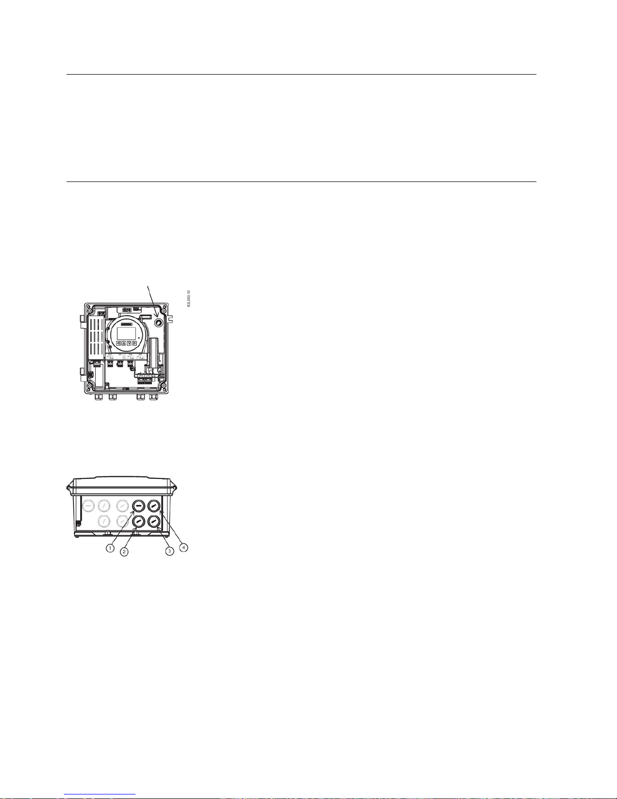
Preparing for the connection
1. Loosen the four lid screws.
2. Open the lid.
3. Remove F-connector tool from wall mount housing.
Figure 4-1 F-connector tool location
Connecting the flow sensor cables
When connecting the sensors it is required for the system to function that the sensor cables are connected correctly. Both
sensor cables for each path must be connected to the same port numbers (1A and 1B or 2A and 2B) on the transmitter.
The sensor cables are delivered with a premounted F-connector at transmitter end.
1. Remove blind plug from wall mount housing.
2. Slide the cable gland back onto the cable and allow access for ther F-connector tool.
3. Place F-connector tool around cable and slide up to engage F-connector nut.
4. Push cable through gland opening. Ensure that center lead is aligned with connector port in transmitter.
5. Tighten F-connector using tool until you meet mechanical stop.

SITRANS FS230
A5E38755607-AA, 02/2017
13
6. Remove F-connector tool.
7. Mount and tighten cable gland.
Repeat these steps for each sensor cable.
SITRANS FS230
14 A5E38755607-AA, 02/2017
4.3
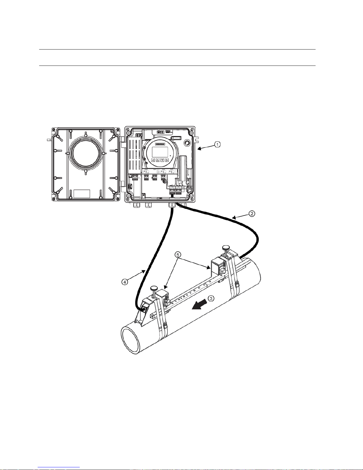
Wall mount
Note
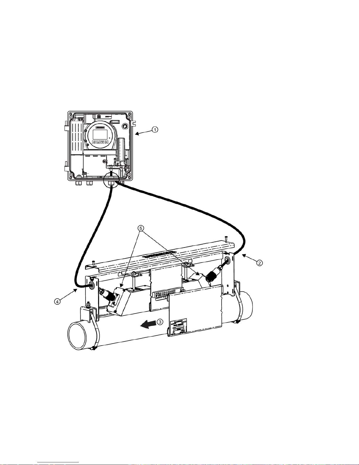
The following example is shown in the Reflect mount sensor configuration.
Connect sensor cables to the wall mounted transmitter as follows:
1. Fill connector end with Super Lube prior to connecting.
2. Apply Super Lube to the internal threads at the large end of the thread connector.
3. Observing the upstream and downstream orientation ③, connect upstream sensor cable ② to the transmitter port (1A)
and make connection snug.
4. Connect the downstream sensor cable
④ to the transmitter port (1B) and make connection snug.
①
Wall mounted transmitter
④
Downstream sensor cable (1B) Path 1
②
Upstream sensor cable (1A) Path 1
⑤
Sensors
③
Flow direction
Figure 4-2 Wall mount housing with transmitter-to- sensor cable connections
5. Tighten all cable glands to obtain optimum sealing.
6. Refer to transmitter FST030 Operating Instructions to program transmitter.
SITRANS FS230
A5E38755607-AA, 02/2017
15
4.4
HI Precision mount
Single enclosure Reflect mount wiring
Connect sensor cables to the transmitter as follows:
1. Fill connector end with Super Lube prior to connecting.
2. Apply Super Lube to the internal threads at the large end of the thread connector.
3. Observing the upstream and downstream orientation ③, connect upstream sensor cable ② to transmitter port (1A) and
make connection snug.
4. Connect downstream sensor cable
④ to the transmitter port (1B) and make connection snug.
①
Wall mounted transmitter
③
Flow direction
②
Upstream sensor cable to internal DSL port
(1A) Path 1
④
Downstream sensor cable to transmitter port (1B) Path 1
⑤
Hi Precision mounted sensors
Figure 4-3 Hi Precision Reflect mount single enclosure wiring
5. Tighten all cable glands to obtain optimum sealing.

SITRANS FS230
16 A5E38755607-AA, 02/2017
Dual enclosure Reflect mount wiring
Referring to the Hi Precision single enclosure reflect mount figure above, connect the Hi Precision mount reflect Dual
enclosure sensor cables to the transmitter ports as follows:
1. Observing the upstream and downstream orientation
③, connect sensor cables to transmitter ports.
2. Tighten all cable glands to obtain optimum sealing.
3. Refer to transmitter FST030 Operating Instructions to program transmitter.
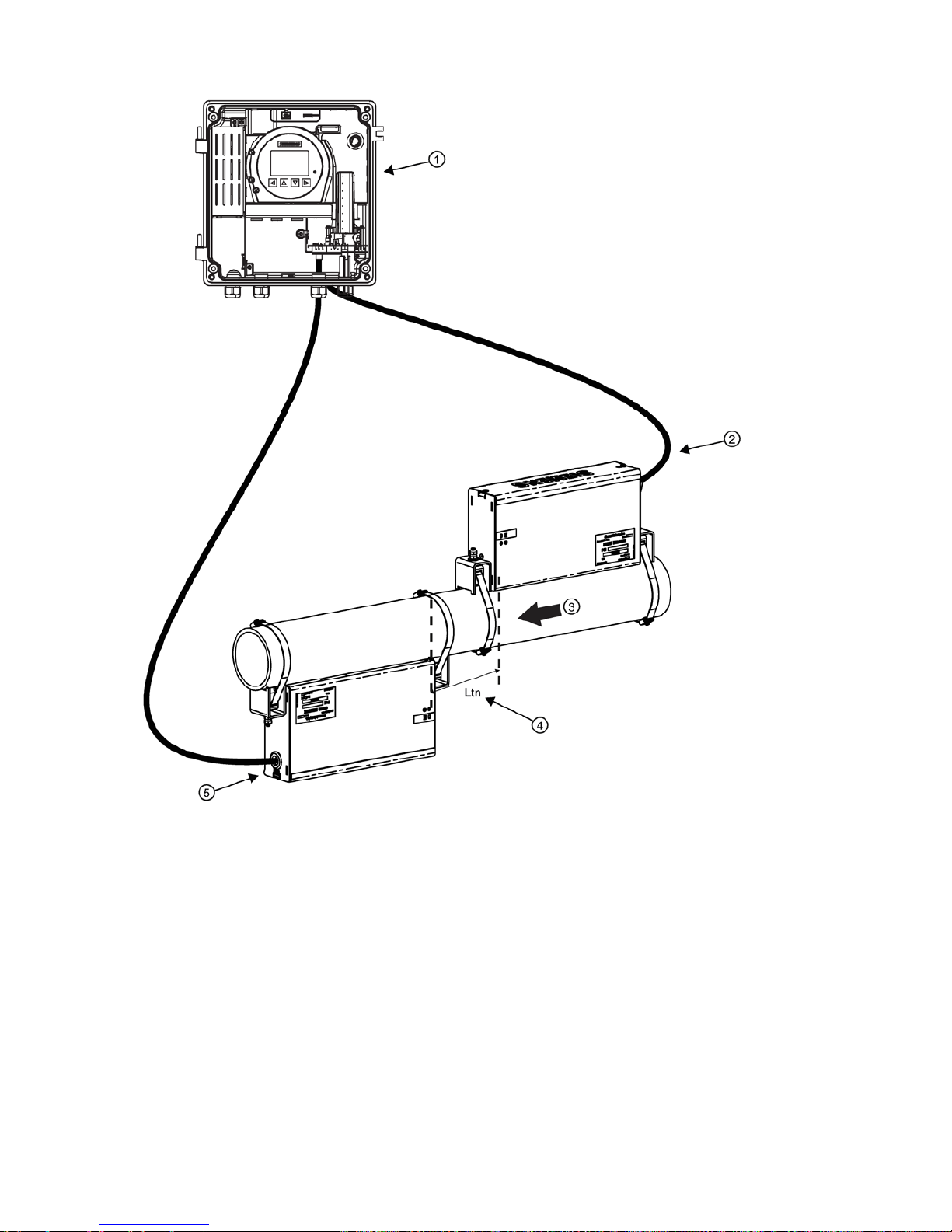
Dual enclosure direct mount wiring
Connect sensor cables to the DSL and transmitter as follows:
1. Fill connector end with Super Lube prior to connecting.
2. Apply Super Lube to the internal threads at the large end of the thread connector.
3. Observing the upstream and downstream orientation ③, connect upstream sensor cable ② to transmitter port (1A) and
make connection snug.
4. Connect downstream sensor cable
⑤ to transmitter port (1B) and make connection snug.
SITRANS FS230
A5E38755607-AA, 02/2017
17
①
Wall mounted transmitter
③
Flow direction
②
Upstream sensor cable to transmitter port
(1A) Path 1
④
Ltn (spacing distance between sensors)
⑤
Downstream sensor cable to transmitter port (1B) Path 1
Figure 4-4 HI Precision Direct mount Dual enclosure sensor wiring
5. Tighten all cable glands to obtain optimum sealing.
6. Refer to transmitter FST030 Operating Instructions to program transmitter.
SITRANS FS230
18 A5E38755607-AA, 02/2017
5
Commissioning
5.1
Basic Safety Notes
5.1.1
Toxic gases and liquids
DANGER
Toxic gases and liquids
Danger of poisoning when venting the device: if toxic process media are measured, toxic gases and liquids can be
released.
• Before venting ensure that there are no toxic gases or liquids in the device, or take the appropriate safety measures.
WARNING
Commissioning and operation with pending error
If an error message appears, correct operation in the process is no longer guaranteed.
• Check the gravity of the error.
• Correct the error.
• If the error still exists:
– Take the device out of operation.
– Prevent renewed commissioning.
5.1.2
Improper commissioning in hazardous areas
WARNING
Improper commissioning in hazardous areas
Device failure or risk of explosion in hazardous areas.
• Do not commission the device until it has been mounted completely and connected in accordance with the information
in Technical data (Page 21).
•
Before commissioning take the effect on other devices in the system into account.
5.1.3
Opening device in energized state
WARNING
Opening device in energized state
Risk of explosion in hazardous areas
• Only open the device in a de-energized state.
• Check prior to commissioning that the cover, cover locks, and cable inlets are assembled in accordance with the
directives.
Exception
: Devices having the type of protection "Intrinsic safety Ex i" may also be opened in energized state in hazardous
areas.
CAUTION
Loss of type of protection
Damage to device if the enclosure is open or not properly closed. The type of protection specified on the nameplate or in
Technical data (Page 21) is no longer guaranteed.
•
Make sure that the device is securely closed.
SITRANS FS230
A5E38755607-AA, 02/2017
19
WARNING
Hazardous contact voltage
Risk of injury through hazardous contact voltage when the device is open or not completely closed.
The degree of protection specified on the nameplate or in Technical data (Page 21) is no longer guaranteed if the device is
open or not properly closed.
•
Make sure that the device is securely closed.
5.1.4
Risk of explosion when medium above 100 °C flows through the process flange
WARNING
Risk of explosion when medium above 100 °C flows through the process flange
Explosion protection is no longer guaranteed and the approval is nullified.
It is prohibited for medium above 100 °C to continually flow through the process
flange.
WARNING
Loss of explosion protection
Risk of explosion in hazardous areas if the device is open or not properly closed.
•
Close the device as described in Connecting (Page 10).
5.1.5
Hot surfaces
WARNING
Hot surfaces
Risk of burns resulting from hot surfaces.
•
Take corresponding protective measures, for example by wearing protective gloves.
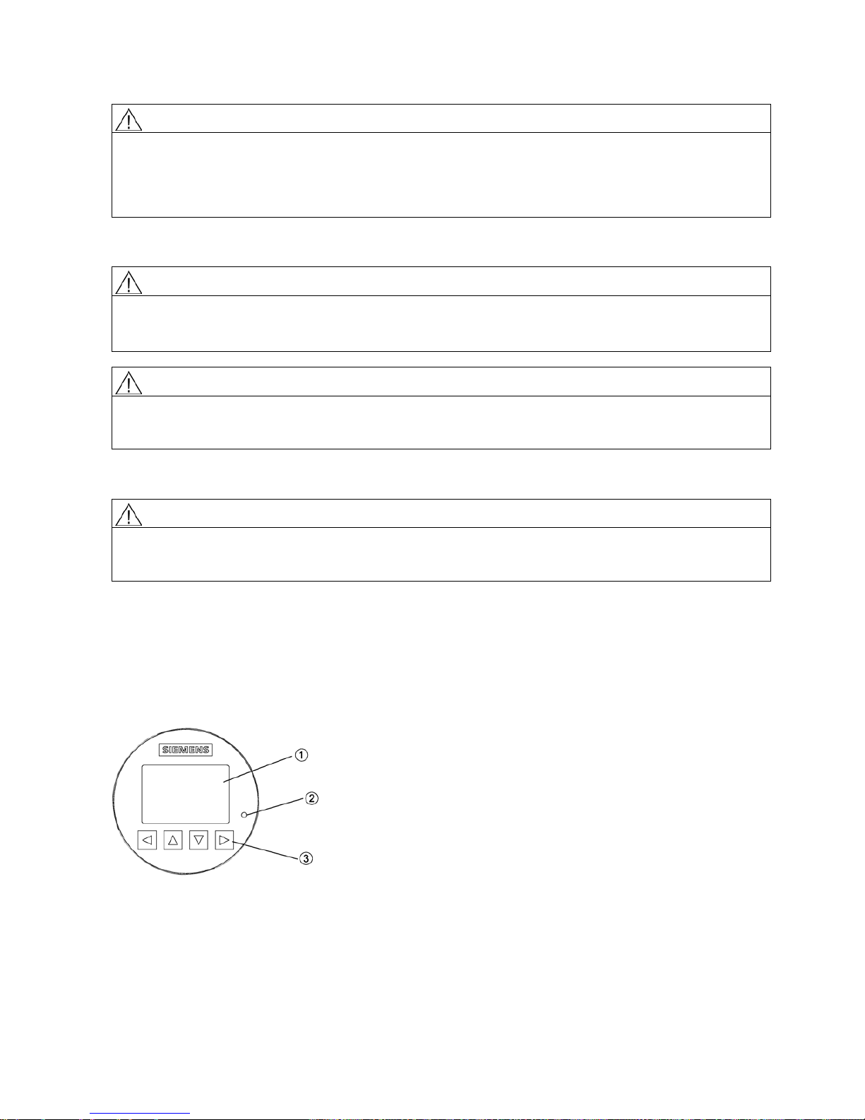
5.2
Local display
The device is commissioned/operated with the touch keypad on the local display.
The elements are actuated by touching the glass panel on the appropriate key. Pressing harder will not activate the key, but
using a thumb instead of a finger tip will help. The text display above the operating elements gives a menu-guided operation
of the individual device function/parameters. Successful operation of the key is confirmed by a small green LED at the right
of the display.
①
Full graphical display
②
LED (for indication of key operation)
③
Touch keypad
Figure 5-1 Local display

SITRANS FS230
20 A5E38755607-AA, 02/2017
Note
(Re-)calibration of the keypad
When the lid is closed, all keys are (re
-)calibrated (< 5 seconds). During (re-)calibration the LED is on and the keys cannot
be operated.
If one of the keys is pressed for more than 10 seconds, the (re
-)calibration of this key begins which has a duration of less
than 10 seconds. Release the key for further operation.
Note
HMI timeout
If no key is pressed for 1
0 minutes, the display switches to show operation view. If Backlight is set to Automatic, display
backlight goes off automatically 30 seconds after the last keypress.
Note
Operation does not require opening of the device. This means that the high degree
of protection of IP67 and safety in
hazardous areas are guaranteed at all times.
5.3
Initial startup
The first time the device is powered up, you will be prompted to set the language. The device always starts up showing
Language in English. When the language has been set, you will be prompted to set the date and time.
Before using the flow meter for the first time, essential parameters should be considered. After confirming/changing date and
time you can choose to accept the default values or start the Quick commissioning wizard.
You will be asked if you want to start the Quick commissioning wizard. If you choose Yes (recommended), the Quick
commissioning wizard will start. If you choose No, you accept the default values of the device, and the next HMI view will be
the operation view 1.
Text
Options/description
Language
Set the language: English, Deutsch, Français, Italiano, Español, 汉语
Welcome
Information about the Quick commissioning wizard
Set date and time
The set date and time (real time clock) is used for all time stamps of logged information
Quick commissioning The Quick commissioning wizard comprises the most important parameters/menus for
quick configuration of the flowmeter

SITRANS FS230
A5E38755607-AA, 02/2017
21
6
Technical data
6.1
Power
Table 6-1 Power supply
Description
Specification
Supply voltage
• 100 to 240 V AC +10/-10%, 47 to 63 Hz
•
20 to 27 V DC +10/-10%
Power consumption
15 VA/7.5 W
Fluctuation
•
Transient overvoltages up to the levels of overvoltage
category II
•
Temporary overvoltages occurring on mains supply only
Reverse polarity protection (y / n)
Y
Galvanic isolation
3000 V AC
6.2
HART interface
Table 6-2 HART communication
Description
Specification
HART revision
7.5
Supported Device Managers
SIMATIC PDM V8.2 SP1 or newer
Supported Device Description (EDD)
V1.00.00
6.3
Operating conditions
Table 6-3 Basic conditions
Description
Specification
Ambient temperature
(Humidity max. 90 %)
Operation:
Transmitter without display
Display
-40 to +60 °C (-40 to +140 °F)
-20 to +60 °C (-4 to +140 °F)
Ambient temperature
(Humidity max. 90 %)
Storage: -40 to +70 °C (-40 to +158 °F)
Climate class DIN 60721-3-4
Altitude
Up to 2000 m (6560 ft)
Relative humidity 95 %
Bump resistance
On request
Shock resistance
On request
Thermal shock
On request
Vibration resistance
On request
EMC performance
•
Emission
• Immunity
•
EN 55011 / CISPR-11
• EN/IEC 61326-1 (Industry)
NAMUR NE 21

SITRANS FS230
22 A5E38755607-AA, 02/2017
Table 6-4 Process medium conditions
Description
Specification
Process medium temperature (Ts) (min to max)
-50 to +200 °C (-58 to 492 °F)
Process medium density (min to max)
1 to 5000 kg/m3 (0.06 to 312 lb/ft3)
Process medium gauge pressure (min to max)
0 to 160 bar (0 to 2321 psi)
Process medium absolute pressure (min to max) Stainless steel: 1 to 101 bar (14.5 to
1465 psi)
Hastelloy: 1 to 161 bar (14.5 to 2335 psi)
Process medium viscosity
Gases and non-compressible liquids
SITRANS FS230
A5E38755607-AA, 02/2017
23
7
Service and maintenance
7.1
Basic safety notes
Note
The device is maintenance
-free.
7.1.1
Maintenance
The device is maintenance-free. However, a periodic inspection according to pertinent directives and regulations must be
carried out.
An inspection can include check of:
● Ambient conditions
● Seal integrity of the process connections, cable entries, and cover screws
● Reliability of power supply, lightning protection, and grounds
NOTICE
Repair and service must be carried out by Siemens authorized personnel only.
Note
Siemens defines flow sensors as non
-repairable products.
WARNING
Impermissible repair and maintenance of the device
•
Repair and maintenance must be carried out by Siemens authorized personnel only.
WARNING
Impermissible repair of explosion protected devices
Risk of explosion in hazardous areas
•
Repair must be carried out by Siemens authorized personnel only.
WARNING
Dust layers above 5 mm
Risk of explosion in hazardous areas.
Device may overheat due to dust build up.
•
Remove dust layers in excess of 5 mm.
NOTICE
Penetration of moisture into the device
Device damage.
•
Make sure when carrying out cleaning and maintenance work that no moisture penetrates the inside of the device.
CAUTION
Releasing button lock
Improper modification of parameters could influence process safety.
•
Make sure that only authorized personnel may cancel the button locking of devices for safety-related applications.
SITRANS FS230
24 A5E38755607-AA, 02/2017
7.2
Cleaning
Cleaning the enclosure
● Clean the outside of the enclosure with the inscriptions and the display window using a cloth moistened with water or a
mild detergent.
● Do not use any aggressive cleansing agents or solvents, e.g. acetone. Plastic parts or the painted surface could be
damaged. The inscriptions could become unreadable.
WARNING
Electrostatic charge
Risk of explosion in hazardous areas if electrostatic charges develop, for example, when cleaning plastic surfaces with a
dry cloth.
•
Prevent electrostatic charging in hazardous areas.
7.3
Maintenance and repair work
WARNING
Maintenance during continued operation in a hazardous area
There is a risk of explosion when carrying out repairs and maintenance on the device in a hazardous area.
• Isolate the device from power.
- or -
•
Ensure that the atmosphere is explosion-free (hot work permit).
WARNING
Impermissible accessories and spare parts
Risk of explosion in areas subject to explosion hazard.
• Only use original accessories or original spare parts.
• Observe all relevant installation and safety instructions described in the instructions for the device or enclosed with the
accessory or spare part.
WARNING
Humid environment
Risk of electric shock.
• Avoid working on the device when it is energized.
• If working on an energized device is necessary, ensure that the environment is dry.
•
Make sure when carrying out cleaning and maintenance work that no moisture penetrates the inside of the device.
CAUTION
Hot surfaces
Risk of burns during maintenance work on parts having surface temperatures exceeding 70 °C (158 °F).
• Take corresponding protective measures, for example by wearing protective gloves.
• After carrying out maintenance, remount touch protection measures.
SITRANS FS230
A5E38755607-AA, 02/2017
25
WARNING
Enclosure open
Risk of explosion in hazardous areas as a result of hot components and/or charged capacitors inside the device.
To open the device in a hazardous area:
1. Isolate the device from power.
2. Observe the wait time specified in Technical data (Page 21) or on the warning sign before opening the device.
3. Visually inspect sensor inlet and outlet.
Exception:
Devices exclusively having the type of protection "Intrinsic safety Ex i" may be opened in an energized state in
hazardous areas.
WARNING
Improper connection after maintenance
Risk of explosion in areas subject to explosion hazard.
• Connect the device correctly after maintenance.
• Close the device after maintenance work.
Refer to Connecting (Page 10).
7.4
Return procedure
Enclose the bill of lading, return document and decontamination certificate in a clear plastic pouch and attach it firmly to the
outside of the packaging.
Required forms
● Delivery note
● Return goods delivery note (http://www.siemens.com/processinstrumentation/returngoodsnote)
with the following information:
– Product (item description)
– Number of returned devices/replacement parts
– Reason for returning the item(s)
● Decontamination declaration (http://www.siemens.com/sc/declarationofdecontamination)
With this declaration you warrant "that the device/replacement part has been carefully cleaned and is free of residues.
The device/replacement part does not pose a hazard for humans and the environment."
If the returned device/replacement part has come into contact with poisonous, corrosive, flammable or water-
contaminating substances, you must thoroughly clean and decontaminate the device/replacement part before returning it
in order to ensure that all hollow areas are free from hazardous substances. Check the item after it has been cleaned.
Any devices/replacement parts returned without a decontamination declaration will be cleaned at your expense before
further processing.
7.5
Disposal
Devices described in this manual should be recycled. They may not be disposed of in the municipal
waste disposal services according to the Directive 2012/19/EC on waste electronic and electrical
equipment (WEEE).
Devices can be returned t
o the supplier within the EC, or to a locally approved disposal service for
eco
-friendly recycling. Observe the specific regulations valid in your country.
Further information about devices containing batteries can be found at: Information about battery /
product return (WEEE) (
https://support.industry.siemens.com/cs/document/109479891/)

SITRANS FS230
26 A5E38755607-AA, 02/2017
A
Appendix A
Technical Support
If this documentation does not provide complete answers to any technical questions you may have, contact Technical
Support at:
● Support request (http://www.siemens.com/automation/support-request
)
● More information about our Technical Support is available at
Technical Support (http://www.siemens.com/automation/csi/service
)
Internet Service & Support
In addition to our documentation, Siemens provides a comprehensive support solution at:
● Services & Support (http://www.siemens.com/automation/service&support)
Personal contact
If you have additional questions about the device, please contact your Siemens personal contact at:
● Partner (http://www.automation.siemens.com/partner)
In order to find the contact for your product, select under 'All Products and Branches' the path 'Automation Technology >
Sensor Systems'.
Documentation
You can find documentation on various products and systems at:
● Instructions and manuals Instructions and manuals (http://www.siemens.com/processinstrumentation/documentation)
A.1 Certificates
You can find certificates on the Internet at Certificates (http://www.siemens.com/processinstrumentation/certificates) or on
an included DVD.
SITRANS FS230
A5E38755607
, 02/2017
Trademarks
All names identified by ® are registered trademarks of
Siemens AG
. The remaining trademarks in this publication may be trademarks whose
use by third parties for their own purposes could violate the rights of the owner.
Disclaimer of Liability
We have reviewed the contents of this publication t
o ensure consistency with the hardware and software described. Since variance cannot
be precluded entirely, we cannot guarantee full consistency. However, the information in this publication is reviewed regular
ly and any
necessary corrections are included
in subsequent editions.
Siemens AG
Division Process Industries and Drives
Postfach 48 48
90026 NÜRNBERG
GERMANY
© Siemens AG 2017. Alle Rechte vorbehalten
A5E38755607-AA, 02/2017
27
SITRANS F
Ultraschall-Durchflussmessgeräte
SITRANS FS230
Kompaktbetriebsanleitung
Rechtliche Hinweise
Warnhinweiskonzept
Dieses Handbuch enthält Hinweise, die Sie zu Ihrer persönlichen Sicherheit sowie zur Vermeidung von Sachschäden beachten müssen.
Die Hinweise zu Ihrer persönlichen Sicherheit sind durch ein Warndreieck hervorgehoben, Hinweise zu alleinigen Sachschäden stehen
ohne Warndreieck. Je nach Gefährdungsstufe werden die Warnhinweise in abnehmender Reihenfolge wie folgt dargestellt.
GEFAHR
bedeutet, dass Tod oder schwere Körperverletzung eintreten
wird
, wenn die entsprechenden Vorsichtsmaßnahmen nicht getroffen
werden.
WARNUNG
bedeutet, dass Tod oder schwere Körperverletzung eintreten
kann
, wenn die entsprechenden Vorsichtsmaßnahmen nicht getroffen
werden.
VORSICHT
bedeutet, dass eine leichte Körperverletzung eintreten kann, wenn die entsprechenden Vorsichtsmaßnahmen nicht getroffen werden.
ACHTUNG
bedeutet, dass Sachschaden eintreten kann, wenn die entsprechenden Vorsichtsmaßnahmen nicht getroffen werden.
Beim Auftreten mehrerer Gefährdungsstufen wird immer der Warnhinweis zur jeweils höchsten Stufe verwendet. Wenn in einem
Warnhinweis mit dem Warndreieck vor Personenschäden gewarnt wird, dann kann im selben Warnhinweis zusätzlich eine Warnung vor
Sachschäden angefügt sein.
Qualifiziertes Personal
Das zu dieser Dokumentation zugehörige Produkt/System darf nur von für die jeweilige Aufgabenstellung
qualifiziertem Personal
gehandhabt werden unter Beachtung der für die jeweilige Aufgabenstellung zugehörigen Dokumentation, insbesondere der darin
enthaltenen Sicherheits- und Warnhinweise. Qualifiziertes Personal ist auf Grund seiner Ausbildung und Erfahrung befähigt, im Umgang mit
diesen Produkten/Systemen Risiken zu erkennen und mögliche Gefährdungen zu vermeiden.
Bestimmungsgemäßer Gebrauch von Siemens-Produkten
Beachten Sie Folgendes:
WARNUNG
Siemens-Produkte dürfen nur für die im Katalog und in der zugehörigen technischen Dokumentation vorgesehenen Einsatzfälle verwendet
werden. Falls Fremdprodukte und -komponenten zum Einsatz kommen, müssen diese von Siemens empfohlen bzw. zugelassen sein. Der
einwandfreie und sichere Betrieb der Produkte setzt sachgemäßen Transport, sachgemäße Lagerung, Aufstellung, Montage, Installation,
Inbetriebnahme, Bedienung und Instandhaltung voraus. Die zulässigen Umgebungsbedingungen müssen eingehalten werden. Hinweise
in den zugehörigen Dokumentationen müssen beachtet werden.

SITRANS FS230
28 A5E38755607-AA, 02/2017
1
Einleitung
1.1
Zweck dieser Dokumentation
Dieses Dokument enthält alle wesentlichen Gesundheits- und Sicherheitsinformationen, die für den sicheren Betrieb des
Gerätes benötigt werden.
Lesen Sie vor Einbau und Inbetriebnahme des Gerätes sorgfältig die Betriebsanleitung auf dem elektronischen Datenträger.
1.2
Revisionsüberblick
Die folgende Übersicht zeigt die wichtigsten Änderungen in der Dokumentation gegenüber der früheren Ausgabe.
Ausgabe
Bemerkungen
FW-Version
HW-Version
EDD-Version
HARTGeräterevision
02/2017
• Erstausgabe
1.00.00 01
• SIMATIC
PDM-Treiber
für HART
1.00.00
• SIMATIC
PDM-Treiber
für Modbus
1.00.00
• AMS-Treiber
für HART
1.00.00
• FC475-Treiber
für HART
1.00.00
• DTM/FDT-
Treiber für
HART 1.00.00
1
1.3
Bestimmungsgemäßer Gebrauch
Dieses Gerät ist zur Messung von Messstoffen gemäß den Informationen in der Betriebsanleitung bestimmt.
Hinweis
Nutzung in häuslicher Umgebung
Diese Einrichtung der Klasse A Gruppe 1 ist für den Einsatz im industriellen Bereich vorgesehen.
In häuslicher Umgebung kann das Gerät Funkstörungen verursachen.
1.4
Überprüfung der Lieferung
1. Prüfen Sie die Verpackung und die gelieferten Artikel auf sichtbare Schäden.
2. Melden Sie alle Schadenersatzansprüche unverzüglich dem Spediteur.
3. Bewahren Sie beschädigte Teile bis zur Klärung auf.
4. Prüfen Sie den Lieferumfang durch Vergleichen Ihrer Bestellung mit den Lieferpapieren auf Richtigkeit und
Vollständigkeit.
 Loading...