

Siemens SITRANS F Series, SITRANS FCT030 Quick Start Manual

© Siemens AG 2012 - 2013. All rights reserved
A5E03922778-006, 12/2013 1
SITRANS F
Coriolis Flowmeters
SITRANS FCT030 transmitter
Quick Start
Before installing, including in hazardous areas, refer to the Operating Instructions on the internet or on the SITRANS F
documentation CD-ROM which is included in the product package. They contain detailed safety regulations, information and
specifications which must be observed when installing. Documentation and approvals can be found on the internet:
Flow documentation (http://www.siemens.com/flowdocumentation)
CAUTION
Proper handling
Correct, reliable operation of the device requires proper transport, storage, positioning and assembly. The device must be
carefully operated and maintained. Only qualified personnel should install or operate this device.
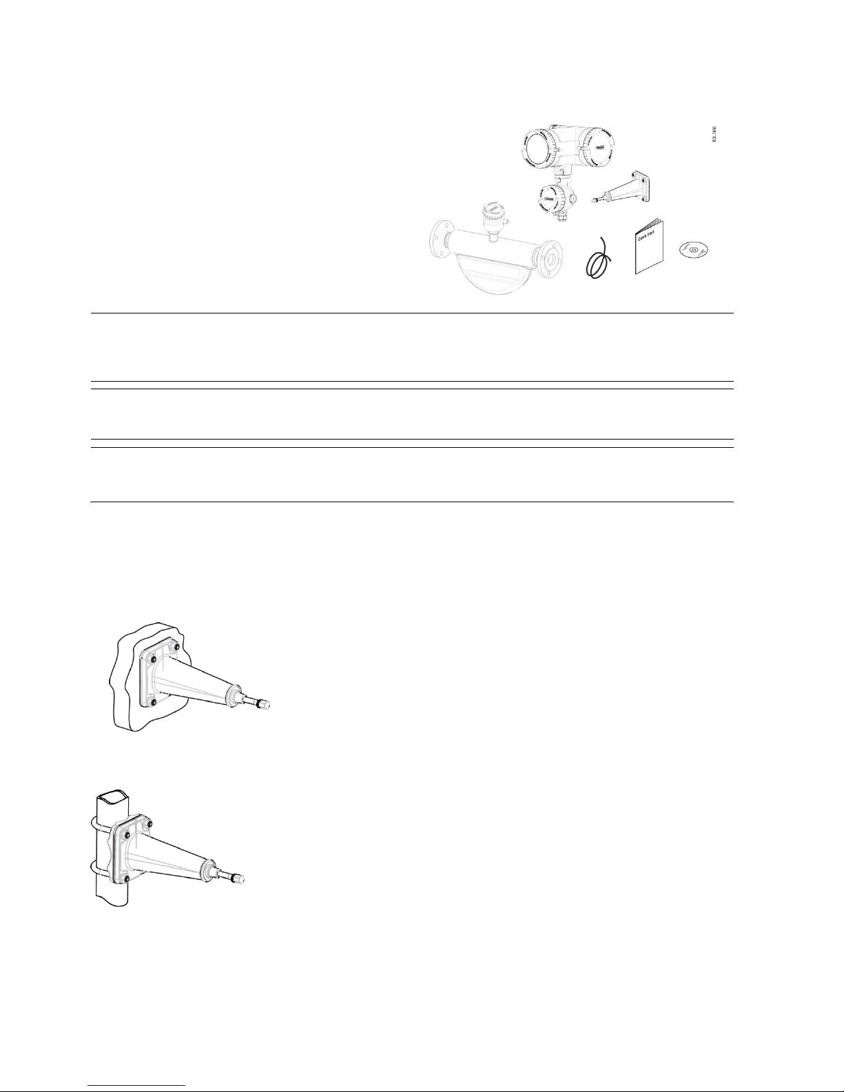
Items supplied
Compact system
● SITRANS FC430 sensor and compact mounted
transmitter
● Packet of cable glands
● Quick Start guide
● CD containing software, certificates and device manuals
Remote system
With M12 connection
● SITRANS FCS400 sensor
● SITRANS FCT030 transmitter with M12 socket assembled
● Mounting bracket and cushion pad
● Sensor cable with M12 connector
● Packet of cable glands
● Quick Start guide
● CD containing software, certificates and device manuals
How to install
SITRANS FCT030 transmitter
2 A5E03922778-006, 12/2013
With terminal housing
● SITRANS FCS400 sensor
● SITRANS FCT030 transmitter with terminal housing
assembled
● Mounting bracket and cushion pad
● Sensor cable
● Packet of cable glands
● Quick Start guide
● CD containing software, certificates and device manuals
Note
Supplementary information
Supplementary product and production specific certificates are included on the SensorFlash® SD card in the transmitter
socket.
Note
Scope of delivery may vary, depending on version and add-ons. The contents list in the product package lists all included
parts.
Note
Sensor installation
The installation of the FCS400 sensor is described in the SITRANS FCS400 Quick Start (A5E03649755).
Remote mounting
Wall mounting
1. Prepare holes with aid of mounting bracket.
2. Fasten mounting bracket with cushion pad to wall (torque 10 Nm).
Pipe mounting
1. Mount mounting bracket with cushion pad on pipe using fastening brackets/U-bolts and supplied pipe adaptor. Note: U-
bolts and other miscellaneous hardware are not supplied with the flowmeter.
2. Tighten nuts (torque 10 Nm).
SITRANS FCT030 transmitter
A5E03922778-006, 12/2013 3
Note
Hygienic applications
If the device is wall or pipe-mounted in a hygienic application, always use domed nuts.
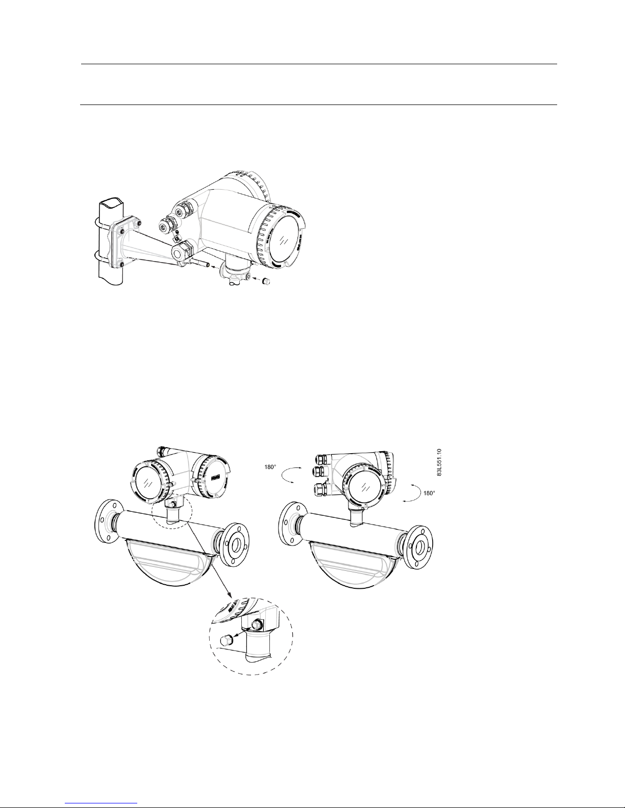
Mounting the transmitter
1. Remove screw from mounting bracket.
2. Mount transmitter on mounting bracket taking care that the flutes on the mating faces are correctly engaged.
3. Firmly tighten screw on mounting bracket (torque: 25 Nm).
Turning the transmitter
In a remote configuration, the transmitter can be turned horizontally and vertically. In a compact configuration, the transmitter
can be turned horizontally only.
Horizontal rotation
1. Unscrew cap from lock screw.
2. Loosen lock screw at transmitter pedestal using 5 mm Allen key.
3. Carefully rotate transmitter into desired position.
4. Firmly tighten lock screw (torque: 10 Nm).
5. Replace cap onto lock screw (torque: 10 Nm).
SITRANS FCT030 transmitter
4 A5E03922778-006, 12/2013
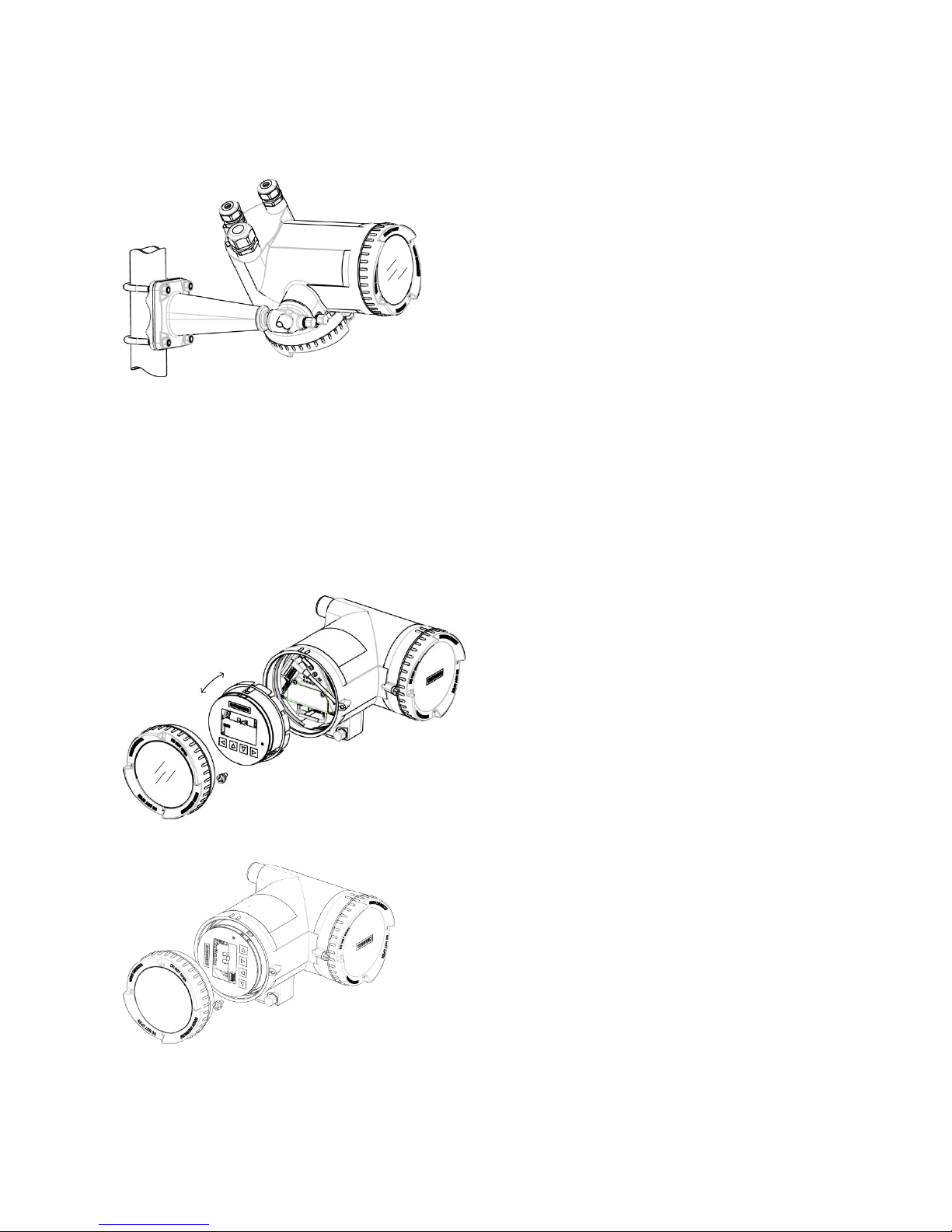
Vertical rotation
1. Loosen locking cap at end of mounting bracket by three turns.
2. Carefully loosen and rotate transmitter into desired position (15° steps).
3. Firmly tighten locking cap (torque: 25 Nm).
Turning the local display
The local display can be turned in steps of 30° in order to optimize the viewing angle.
1. Remove lid lock screw of display cover.
2. Remove display cover.
3. Use a small screwdriver or blade to loosen the three retaining clips within the transmitter.
4. Carefully pull out local display.
5. Turn display into desired position.
6. Carefully push display back into housing. Use a small screwdriver or blade to open the three retaining clips within the
transmitter when pushing the LUI home.
7. Remove o-ring from lid.
SITRANS FCT030 transmitter
A5E03922778-006, 12/2013 5
8. Reinstate display cover until mechanical stop. Wind back lid by one turn.
9. Mount o-ring by pulling it over the display cover and turn display cover until you feel friction from the o-ring on both sides.
Wind display cover further by one quarter of a turn to seal on the o-ring.
10. Reinstate and tighten lid lock screw.
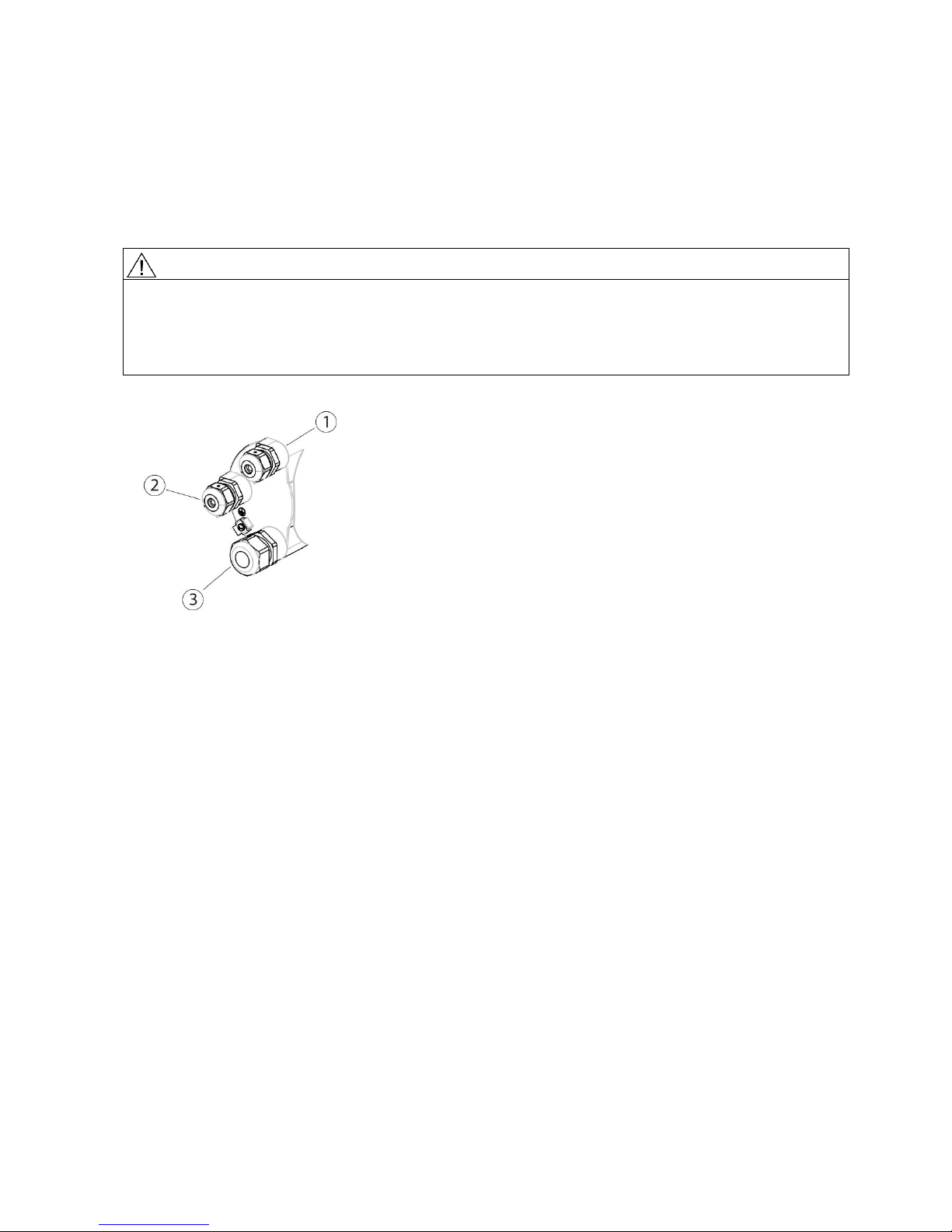
Connecting
WARNING
Access to terminal space
As long as the device is energized, the lid of the housing on the sensor connection area may only be opened by qualified
personnel.
Before removing the terminal cover, the auxiliary power must be switched off from all poles.
Following installation, the terminal cover must be screwed back on again.
1. Remove blind plugs where required and mount cable glands.
①
Input/output connection (channels 2 to 4)
②
Power supply connection
③
Current output/HART connection (channel 1)
2. Remove lid lock screw for terminal connections lid.
3. Remove lid for terminal connections.
SITRANS FCT030 transmitter
6 A5E03922778-006, 12/2013
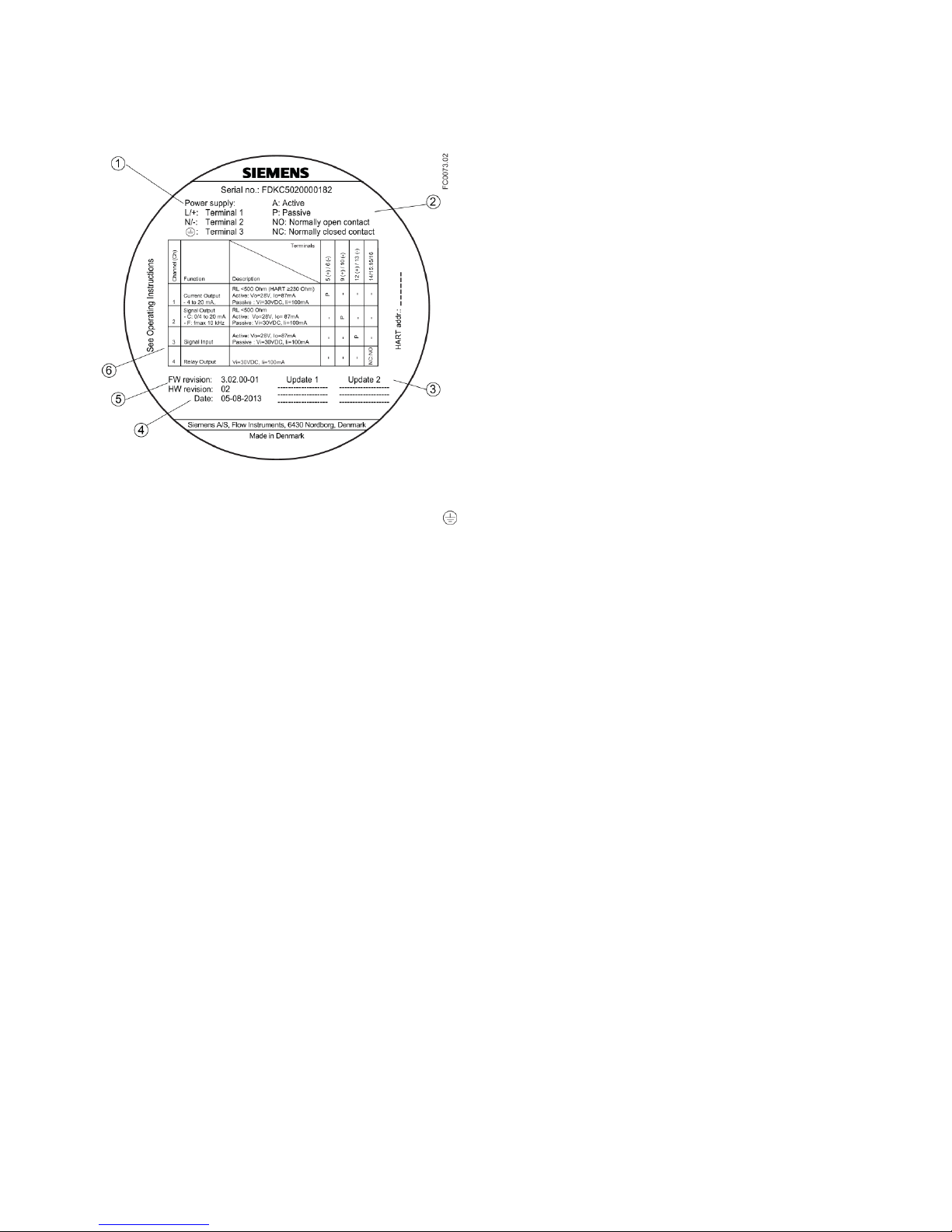
Application terminals
A label showing the configuration is placed at the back of the terminal connections lid.
①
Power supply connections
L/+
Terminal 1
N/-
Terminal 2
Terminal 3
②
Key to symbols
A
Configured as active input/output
P
Configured as passive input/output
NO
Connected as normally open contact
NC
Connected as normally closed contact
③
Updates (to be filled in on firmware and hardware updates)
④
Device configuration date
⑤
Initial firmware and hardware revisions
⑥
Configuration of channels 1, 2, 3 and 4
Figure 3-1 Configuration label
SITRANS FCT030 transmitter
A5E03922778-006, 12/2013 7
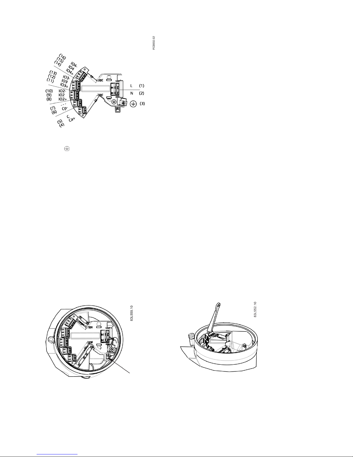
(1)
L/+
Line
(2)
N/-
Neutral
(3) Ground
(4)
Ca+
Used in current output active configuration
(5) C Used in current output active and passive configuration
(6)
Cp-
Used in current output passive configuration
(7)
---
Not used
(8)
IO2+
Signal output channel 2 positive
(9)
IO2
Signal output channel 2 common
(10)
IO2-
Signal output channel 2 negative
(11)
IO3+
Input/output channel 3 positive
(12)
IO3
Input/output channel 3 common
(13)
IO3-
Input/output channel 3 negative
(14)
IO4+
Input/output channel 4 positive
(15)
IO4
Input/output channel 4 common
(16)
IO4-
Input/output channel 4 negative
Figure 3-2 Terminal layout
Wiring tool
Use the wiring tool for connecting the cables.
The wiring tool is located in the application terminal space.
Wiring tool location
How to use the wiring tool

SITRANS FCT030 transmitter
8 A5E03922778-006, 12/2013
1. Insert wiring tool hook into receptor slot.
2. Press wiring tool wedge into top slot to spread clamp plates.
3. Insert wire.
4. Release wiring tool.
Power supply
1. Flip open power supply terminal protection cover.
2. Remove cap and ferrule from cable gland and slide onto cable.
3. Push cable through open gland and cable path.
4. Restore ferrule and tighten cap to lightly hold cable in place.
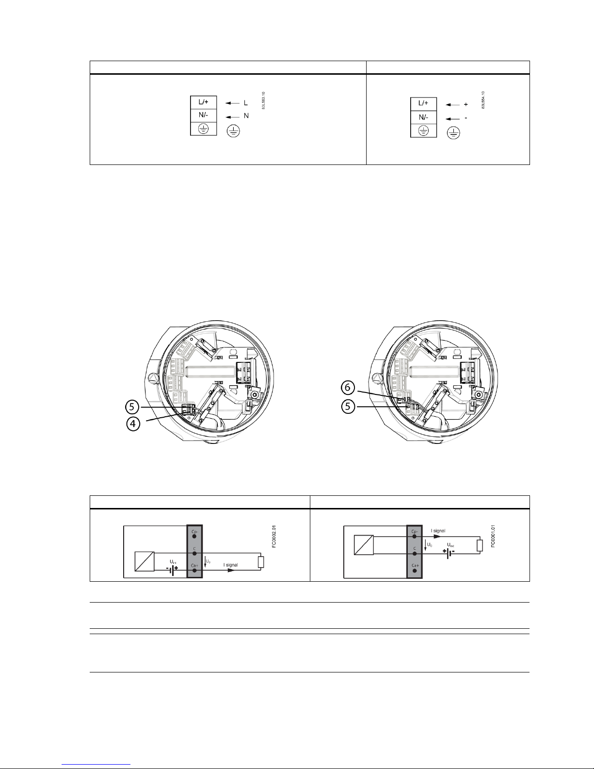
5. Connect ground to terminal and power to terminals L/+ and N/- using wiring tool in the manner shown below at right.
①
L/+
②
N/-
③
SITRANS FCT030 transmitter
A5E03922778-006, 12/2013 9
AC connection
DC connection
Power: 100 to 240 VAC +10/-15%, 47 to 63 Hz
Power: 20 to 27 VDC +10/-10%
6. Close and latch power supply terminal protection cover.
7. Tighten cable gland.
Current output/HART (channel 1)
1. Remove cap and ferrule from cable gland and slide onto cable.
2. Push cable through open gland and cable path.
3. Restore ferrule and tighten cap to lightly hold cable in place.
4. Signal cable screen is folded back over outer sheath and grounded beneath cable clamp.
5. Connect wires to terminals using wiring tool.
Active current output
Passive current output
⑤ C ⑥
Cp- ④ Ca+ ⑤ C
Active current output
Passive current output
6. Tighten cable gland.
Note
Active or passive current output is preselected at ordering.
Note
Load
Current output (channel 1): < 500 Ω (HART ≥ 230 Ω)

SITRANS FCT030 transmitter
10 A5E03922778-006, 12/2013
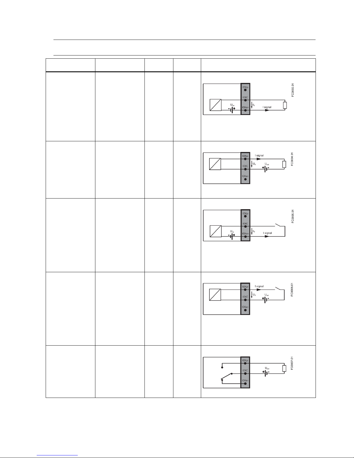
Inputs and outputs (channels 2 to 4)
1. Remove cap and ferrule from cable gland and slide onto cable.
2. Push cable through open gland and cable path.
3. Restore ferrule and tighten cap to lightly hold cable in place.
4. Fold signal cable screen back over outer sheath and ground beneath cable clamp.
5. Connect wires to terminals using wiring tool.
Active current output
Passive current output
⑫
IO[3] (common)
⑬
IO[3]- (passive)
⑪
IO[3]+ (active)
⑫
IO[3] (common)
Termination example for channel 3
6. Tighten cable gland.
SITRANS FCT030 transmitter
A5E03922778-006, 12/2013 11
Note
Active or passive current output is preselected at ordering.
Factory
configuration
Software
configuration
Channel 2
Channel 3,
Channel 4
Signal output
Active
Current Output
Pulse Output
Frequency Output
Status Output
If Status Output:
Alarm Class
Alarm Item
Primary Valve
Dosing Control
Secondary Valve
Dosing Control
X
X
Signal output
Passive
Current Output
Pulse Output
Frequency Output
Status Output
If Status Output:
Alarm Class
Alarm Item
One Stage Dosing
Two Stage Dosing
X
X
Signal input
Active
Start Dosing
Stop Dosing
Reset Totalizer 1
Reset Totalizer 2
Reset Totalizer 3
Reset All Totalizers
Start Zero Point
Adjustment
Pause/Resume
dosing
Force Output
Freeze Output
X
Signal input
Passive
Start Dosing
Stop Dosing
Reset Totalizer 1
Reset Totalizer 2
Reset Totalizer 3
Reset All Totalizers
Start Zero Point
Adjustment
Pause/Resume
dosing
Force Output
Freeze Output
X
Relay output
Alarm Class
Alarm Item
One Stage Dosing
Two Stage Dosing
X
Normally open
 Loading...