

Page 1

SITRANS F
Coriolis Flowmeters
FCT030 Profibus (From firmware
4.0)
Introduction
1
Function Manual
Communication
Cable specifications
Definitions
2
3
4
06/2018
A5E39931906-AB
Page 2
Legal information
Warning notice system
This manual contains notices you have to observe in order to ensure your personal safety, as well as to prevent
damage to property. The notices referring to your personal safety are highlighted in the manual by a safety alert
symbol, notices referring only to property damage have no safety alert symbol. These notices shown below are
graded according to the degree of danger.
DANGER
indicates that death or severe personal injury will result if proper precautions are not taken.
WARNING
indicates that death or severe personal injury may result if proper precautions are not taken.
CAUTION
indicates that minor personal injury can result if proper precautions are not taken.
NOTICE
indicates that property damage can result if proper precautions are not taken.
If more than one degree of danger is present, the warning notice representing the highest degree of danger will be
used. A notice warning of injury to persons with a safety alert symbol may also include a warning relating to property
damage.
Qualified Personnel
The product/system described in this documentation may be operated only by personnel qualified for the specific
task in accordance with the relevant documentation, in particular its warning notices and safety instructions. Qualified
personnel are those who, based on their training and experience, are capable of identifying risks and avoiding
potential hazards when working with these products/systems.
Proper use of Siemens products
Note the following:
WARNING
Siemens products may only be used for the applications described in the catalog and in the relevant technical
documentation. If products and components from other manufacturers are used, these must be recommended or
approved by Siemens. Proper transport, storage, installation, assembly, commissioning, operation and
maintenance are required to ensure that the products operate safely and without any problems. The permissible
ambient conditions must be complied with. The information in the relevant documentation must be observed.
Trademarks
All names identified by ® are registered trademarks of Siemens AG. The remaining trademarks in this publication
may be trademarks whose use by third parties for their own purposes could violate the rights of the owner.
Disclaimer of Liability
We have reviewed the contents of this publication to ensure consistency with the hardware and software described.
Since variance cannot be precluded entirely, we cannot guarantee full consistency. However, the information in
this publication is reviewed regularly and any necessary corrections are included in subsequent editions.
Siemens AG
Division Process Industries and Drives
Postfach 48 48
90026 NÜRNBERG
GERMANY
Document order number: A5E39931906
Ⓟ 05/2018 Subject to change
Copyright © Siemens AG 2018.
All rights reserved
Page 3

Table of contents
1 Introduction...................................................................................................................................................5
1.1 Purpose of this documentation.................................................................................................5
1.2 Document history.....................................................................................................................5
1.3 Product compatibility................................................................................................................6
2 Communication.............................................................................................................................................7
2.1 Features...................................................................................................................................7
2.2 Installation in hazardous area..................................................................................................7
2.3 Profibus....................................................................................................................................7
2.4 Wall mount housing transmitter exploded view........................................................................9
2.5 Changing Profibus termination at the transmitter cassette....................................................10
2.6 Connecting the Profibus (CH1)..............................................................................................12
2.7 Installation check....................................................................................................................13
2.8 Cyclic services.......................................................................................................................14
2.9 Cyclic data exchange.............................................................................................................15
2.10 Acyclic communication...........................................................................................................26
2.11 Access Control.......................................................................................................................63
2.12 Alarm, error, and system messages......................................................................................64
2.12.1 Introduction............................................................................................................................64
2.12.2 Diagnosis Response..............................................................................................................64
3 Cable specifications....................................................................................................................................67
4 Definitions...................................................................................................................................................69
Index...........................................................................................................................................................73
FCT030 Profibus (From firmware 4.0)
Function Manual, 06/2018, A5E39931906-AB 3
Page 4

Table of contents
FCT030 Profibus (From firmware 4.0)
4 Function Manual, 06/2018, A5E39931906-AB
Page 5

Introduction
1.1 Purpose of this documentation
This manual contains all information needed to integrate the process instruments into a
communications network. The manual is aimed at control system designers, system
integrators, instrument engineers.
In order to operate safety and for more detailed information you need the product specific
manual. Available for download from Flow documentation (http://www.siemens.com/
flowdocumentation).
This manual applies to the SITRANS FCT030 transmitter Profibus DP/PA version only. The
FCT030 transmitter can be used in combination with the following sensors:
Mass 2100
FC300
FCS400 and FCS300
In order to operate a Coriolis flow meter, you also need Operating Instructions. See Flow
documentation (http://www.siemens.com/flowdocumentation)
1
1.2 Document history
The following table shows major changes in the documentation compared to the previous
edition.
The most important changes in the documentation when compared with the respective
previous edition are given in the following table.
Edition Note
06/2018 Second edition
06/2017 First edition
Use the device to measure process medium in accordance with the information in the
Operating Instructions.
Note
Use in a domestic environment
This Class A Group 1 equipment is intended for use in industrial areas.
In a domestic environment this device may cause radio interference.
FCT030 Profibus (From firmware 4.0)
Function Manual, 06/2018, A5E39931906-AB 5
Page 6

Introduction
1.3 Product compatibility
1.3 Product compatibility
Edition Remarks Product compatibility Compatibility of device integration package
06/2017 First revision HW revision 03
Compact FW revision 4.xx.xx-xx
Remote FW revision 4.xx.xx-xx
05/2015 Aerated Flow
parameters
added
05/2014 Description of
new parame‐
ters for spare
part replace‐
ment
12/2013 Various LUI
functions, for
example wiz‐
ards Various
transmitter
functionalities
06/2012 CT chapter in‐
cluded
03/2012 First edition HW revision 01
HW revision 02
Compact FW revision
3.02.02-01
Remote FW revision 2.02.02-01
HW revision 02
Compact FW revision 3.02.01
Remote FW revision 2.02.01
HW revision 02
Compact FW revision 3.02.00
Remote FW revision2.02.00
HW revision 01
Compact FW revision
3.00.00-10
Remote FW revision2.00.00-30
Compact FW revision 2.00.0x
Remote FW revision
2.00.0x
Service channel: SIMATIC
V8.2 Service Pack 1 or later
Modbus: SIMATIC V8.2 Serv‐
ice Pack 1 or later
HART: SIMATIC V8.2 Serv‐
ice Pack 1 or later
HART: SITRANS DTM V4.1 5.00.xx-xx
HART: AMS Device manager
V12
PROFIBUS: SIMATIC V8.2
Service Pack 1 or later
PROFIBUS : SITRANS DTM
V4.1
SIMATIC PDM HART 4.00.00-00
SIMATIC PDM Service chan‐
nel
AMS Device Manager HART 4.00.00-02
SITRANS DTM HART 4.00.00-00
375 Field Communicator
HART
SIMATIC PDMAMS Device
ManagerSITRANS DTM375
Field Communicator
SIMATIC PDMAMS Device
ManagerSITRANS DTM375
Field Communicator
SIMATIC PDM EDD Version 1.00.00
SIMATIC PDM EDD Version 1.00.00
5.00.xx-xx
5.00.xx-xx
5.00.xx-xx
5.00.xx-xx
1.00.xx-xx
1.00.xx-xx
4.00.00-00
4.00.00-02
3.00.00-00
EDD Version 2.00.00
FCT030 Profibus (From firmware 4.0)
6 Function Manual, 06/2018, A5E39931906-AB
Page 7

Communication
2.1 Features
The device provides the following features:
● PROFIBUS DP communication up to 12 Mbit/s
● Automatic baud rate adaption
● PROFIBUS PA communication
● Automatic baud rate adaption
● Cyclic communication
● Acyclic communication to SIMATIC S7 or other PLCs
● Acyclic communication to SIMATIC PDM or other parameterization tools
● Support of high availability systems like SIMATIC S7 H
● Support of PROFIBUS PA Profile for Process Control Devices V4.0 and V3
● Automatic GSD adaption
● Support of up to 15 modules (process values and control values), in cyclic communication
● PROFIBUS clock synchronization by master
2
2.2 Installation in hazardous area
The PROFIBUS DP module is not allowed for use in hazardous areas.
The PROFIBUS PA module is allowed for use in hazardous areas.
2.3 Profibus
The transmitter has a modular design with discrete, replaceable electronic modules and
connection boards to maintain separation between functions and facilitate field service. All
modules are fully traceable and their provenance is included in the transmitter setup.
The bus termination can be activated via a switch internal in the transmitter. The bus
termination switch is set to off by default. If the internal switch is not used for termination an
external separate bus terminator must be installed. The internal switch is located to on the
transmitter PCBA module (9)
FCT030 Profibus (From firmware 4.0)
Function Manual, 06/2018, A5E39931906-AB 7
Page 8
D
E
D
/
E
Communication
2.3 Profibus
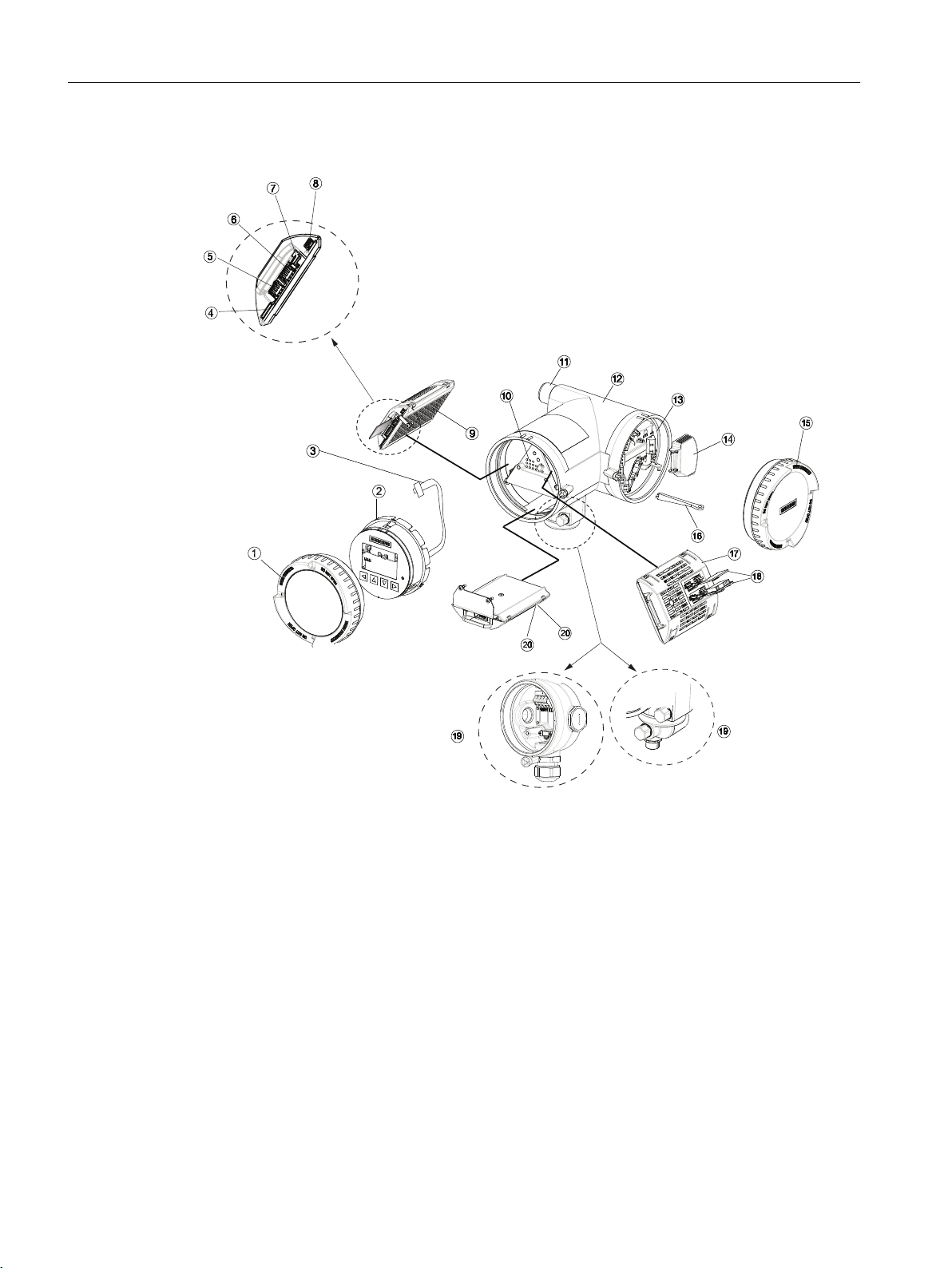
Transmitter exploded view
① Display cover ⑫ Transmitter housing
② Local display (HMI) ⑬ Terminal space
③ Connector for HMI ⑭ Power supply terminal protection cover
④ SD card (SensorFlash) ⑮ Lid for terminal connections
⑤ DIP switch (for custody transfer) ⑯ Wiring tool
⑥ DIP switch (for HART) ⑰ I/O cassette (optional)
⑦ HMI port ⑱ I/O configuration keys (optional)
⑧ USB service port ⑲a M12 socket
⑨ Transmitter cassette ⑲b Terminal housing
⑩ Heatsink cover for power supply module ⑳a Sensor module (compact version)
⑪ Cable entry ⑳b Sensor module (remote version)
Figure 2-1 Transmitter exploded view
8 Function Manual, 06/2018, A5E39931906-AB
FCT030 Profibus (From firmware 4.0)
Page 9
2.4 Wall mount housing transmitter exploded view
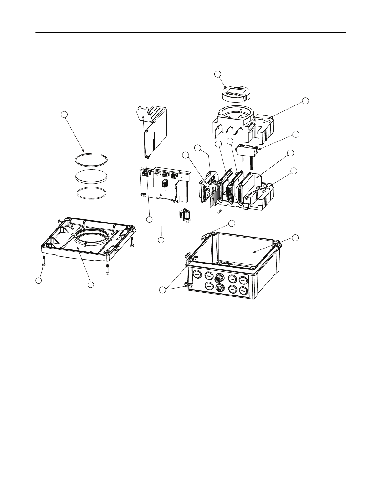
2.4 Wall mount housing transmitter exploded view
Communication
① Display glass with retaining ring ⑩ Foam bottom
② Power supply module (complete) ⑪ Hinge pin
③ SensorFlash (SD card) ⑫ Housing
④ Transmitter cassette ⑬ Ground connect set
⑤ IO cassette ⑭ Backplane module
⑥ HMI module ⑮ Power supply connector cover
⑦ Foam top ⑯ Front cover enclosure
⑧ Foam plugs ⑰ Front cover mounting screws
⑨ Sensor module (analog version)
Barrier module (digital version)
Figure 2-2 Wall mount housing transmitter exploded view
FCT030 Profibus (From firmware 4.0)
Function Manual, 06/2018, A5E39931906-AB 9
Page 10
Communication
2.5 Changing Profibus termination at the transmitter cassette
2.5 Changing Profibus termination at the transmitter cassette
To change the termination of the Profibus, it is required to remove the transmitter module out
of the transmitter. This can be done following below instructions.
1. Isolate the device from power.
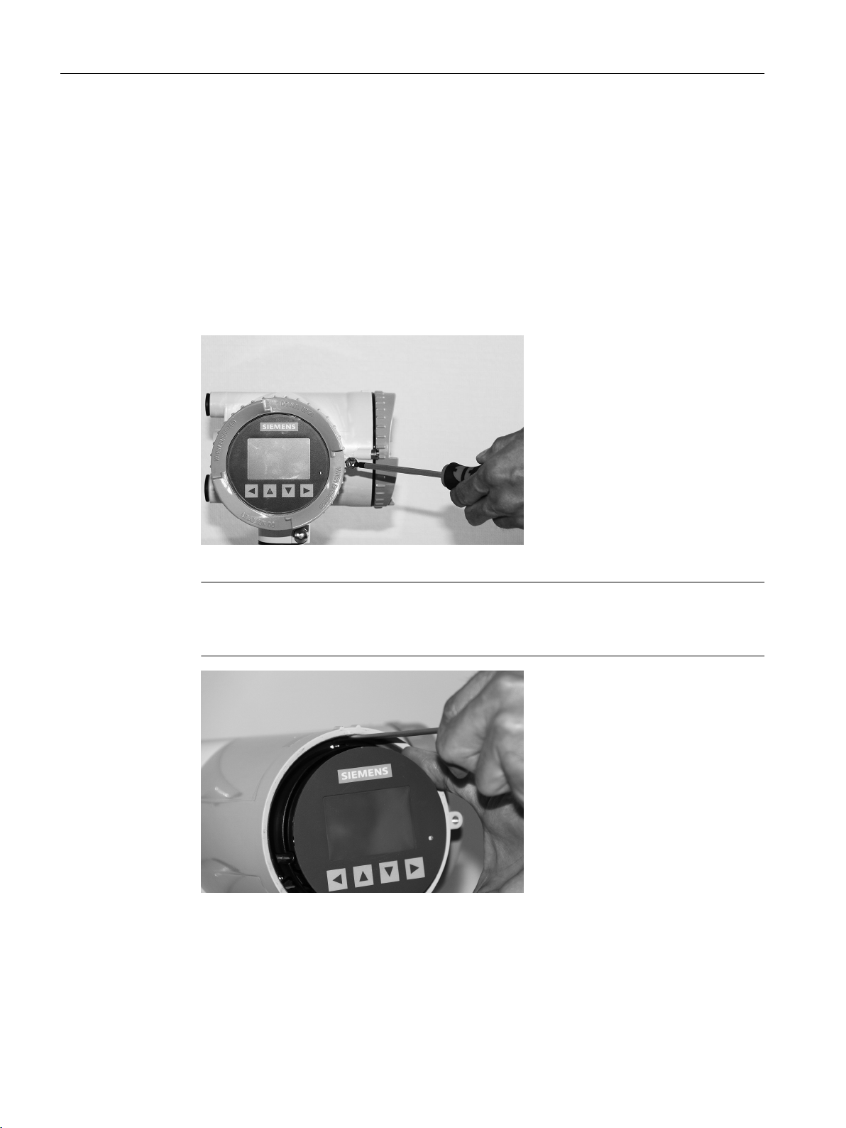
2. Using tool no. 9, unscrew the locking screw of the display and remove the display lid using
tool no. 3 as a wrench bar if necessary.
3. Carefully remove display and cable plug.
Note
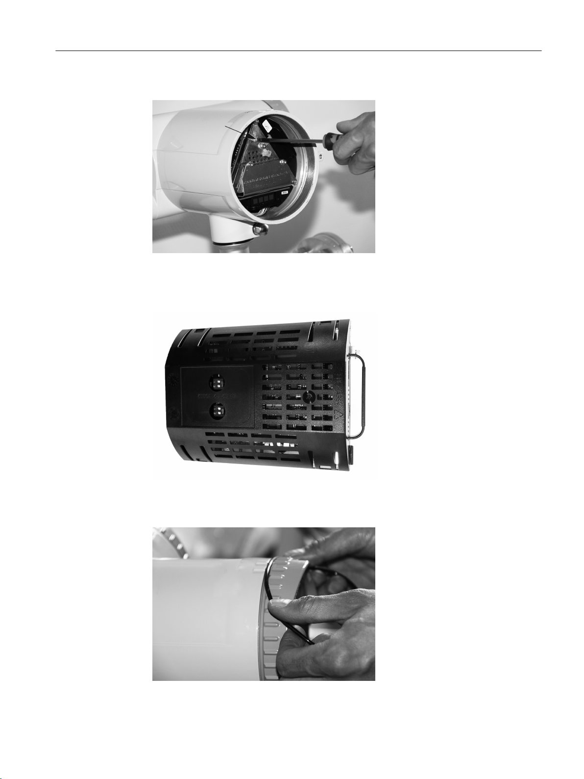
Use a screwdriver, tool no. 11, to release the display as shown in photo below.
The display is held in place with three clips.
FCT030 Profibus (From firmware 4.0)
10 Function Manual, 06/2018, A5E39931906-AB
Page 11
Communication
2.5 Changing Profibus termination at the transmitter cassette
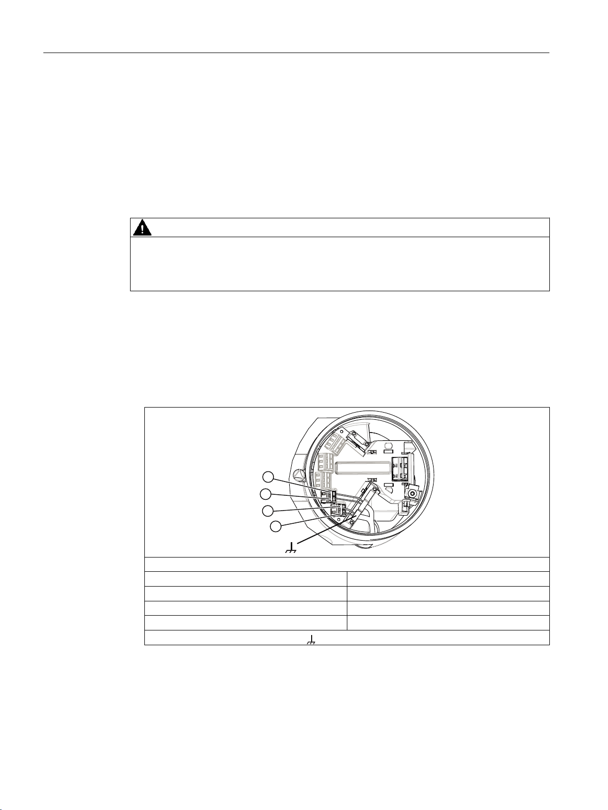
4. Remove the screw holding the transmitter cassette. Pull out the transmitter cassette.
5. Changing termination at the transmitter cassette, by changing the position of the dip
switches as below.
All off: no termination
All on: termination activated
6. Reinstall the transmitter cassette.
Reinstall the display and display cable, incl. the O-ring.
Mount the O-ring by pulling it over the display lid.
FCT030 Profibus (From firmware 4.0)
Function Manual, 06/2018, A5E39931906-AB 11
Page 12
Communication
2.6 Connecting the Profibus (CH1)
Return the device to operation
1. Restore power to the device.
2. Check that the device starts up as expected. If possible watch the display during startup
and observe the device versions for consistency.
2.6 Connecting the Profibus (CH1)
WARNING
Passive channels only
Channel 1 power supply must be separated from that for channels 2 to 4.
Signal return (or common) can be joined.
1. Remove cap and ferrule from cable gland and slide onto cable.
2. Push cable through open gland and cable path.
3. Restore ferrule and tighten cap to lightly hold cable in place.
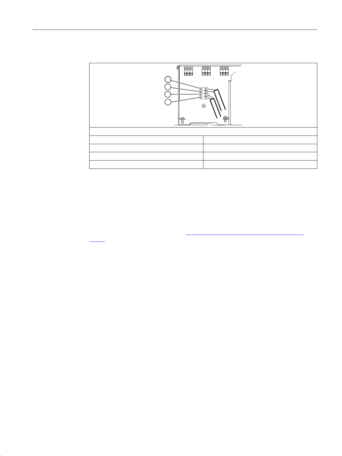
4. Signal cable screen is folded back over outer sheath and grounded beneath cable clamp.
5. Connect wires to terminals using wiring tool, field mount transmitter
PROFIBUS DP/PA
④ In + (B)
⑤ In - (A)
⑥ Out + (B)
⑦ Out - (A)
Functional Earth
12 Function Manual, 06/2018, A5E39931906-AB
FCT030 Profibus (From firmware 4.0)
Page 13
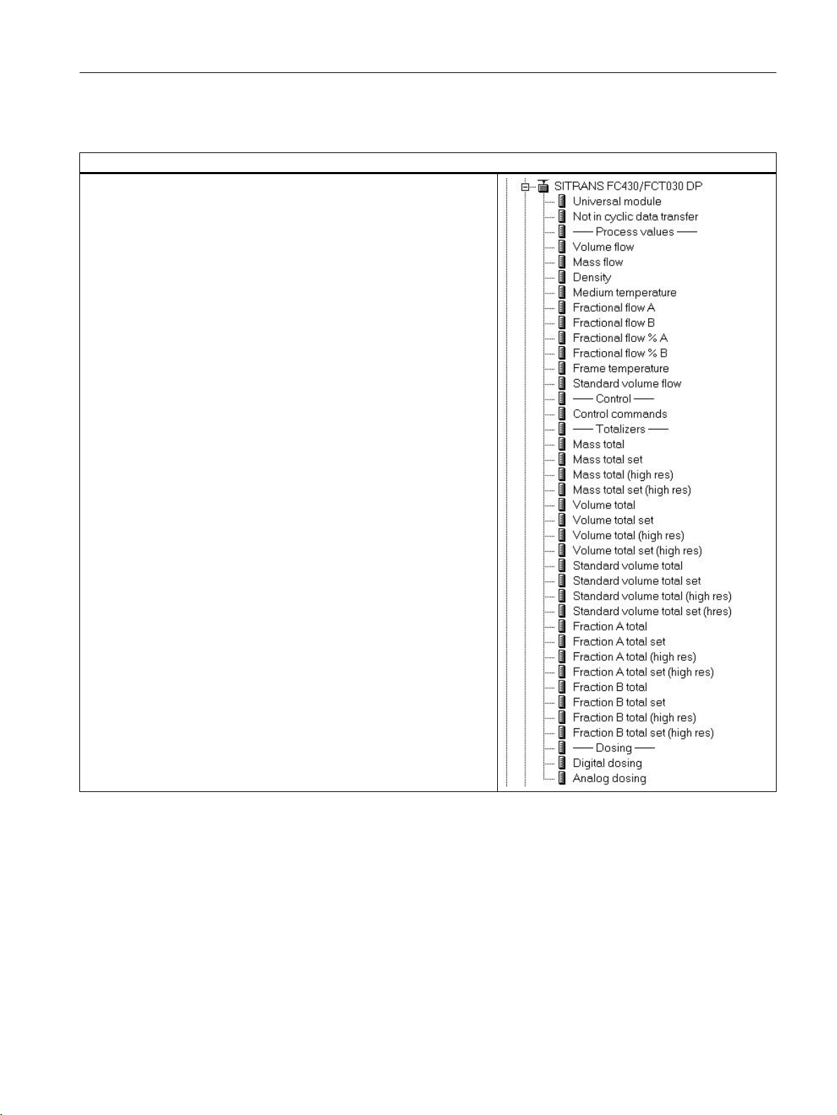
6. Connect wires to terminals using wiring tool, wall mount transmitter.
PROFIBUS DP/PA
④ In + (B)
⑤ In - (A)
⑥ Out + (B)
⑦ Out - (A)
7. Tighten cable gland.
Communication
2.7 Installation check
2.7 Installation check
● Make sure the installation guidelines provided by the "Wiring & Installation Application
Guide" on Profibus Installation guide (http://www.profibus.com/download/installation-
guide/) are followed.
● Make sure the wiring requirements for the device are met.
● Make sure all connectors are properly tightened.
FCT030 Profibus (From firmware 4.0)
Function Manual, 06/2018, A5E39931906-AB 13
Page 14

Communication
2.8 Cyclic services
2.8 Cyclic services
Below is an overview of which cyclic services and parameter update time the device provides.
Input (Master view) is defined as values from the flowmeter to the master. Output (Master view)
is defined as values from the master to the flowmeter. Update time is the interval the flowmeter
updates the parameters.
Parameter name Update time
Input (Master view) Mass flow 10 msec
Output (Master view) Dosing control:
Density 10 msec
Medium temperature 30 msec
Totalizer 1 (single and double preci‐
sion)
Totalizer 2 (single and double preci‐
sion)
Fractional flow A 10 msec
Fractional flow B 30 msec
Fractional flow % A 30 msec
Fractional flow % B 30 msec
Standard volume flow 10 msec
Frame temperature 30 msec
Totalizer 3 (single and double preci‐
sion)
Control status:
● Zero point adjustment active
● Outputs forced
● Process values frozen
Dosing:
● Dosing amount done
● Dosing status
● Dosing output (analogue /
discrete)
● Start
● Stop
● Pause
● Resume
● Clean
Start zero point adjustment
Force / unforce outputs
Freeze / unfreeze process values
Control totalizer 1
Control totalizer 2
Control totalizer 3
10 msec
30 msec
30 msec
30 msec
30 msec
FCT030 Profibus (From firmware 4.0)
14 Function Manual, 06/2018, A5E39931906-AB
Page 15

Communication
2.9 Cyclic data exchange
2.9 Cyclic data exchange
A central controller that cyclically exchanges data with slave devices on a PROFIBUS network
is called a Master class 1 device. A GSD file is normally used when setting up the master to
exchange data with the slave device. The order of the data in the cyclic message is the same
as the order in the GSD file.
Each device supports three different GSD files. The manufacturer specific and the
manufacturer independent Profile 3 GSD-files are described in the following.
Supported GSD files
The DP/ PA version of the SITRANS FCT030 supports the following GSD files
DP version PA version
GSD Description GSD Description
si0181CB.gsd SITRANS FC330 / FC430 /
FCT030 manufacturer specif‐
ic GSD for DP
si018127.gsd SITRANS FC MASS6000 DP si018128.gsd SITRANS FC MASS6000 PA
pa05B333.gsd PA Profile 4 Specific GSD for
Coriolis flow devices DP
(Mass flow, Density, Medium
temperature, Totalizer 1 -
Mass)
pa039700.gsd PA Profile 3 Specific GSD (1
Analog Input, DP)
pa039701.gsd PA Profile 3 Specific GSD (2
Analog Inputs, DP)
pa039702.gsd PA Profile 3 Specific GSD (3
Analog Inputs, 1 Totalizer,
DP)
pa039742.gsd PA Profile 3 Specific GSD (3
Analog Inputs, 1 Totalizer,
DP)
si0181CC.gsd SITRANS FC330 / FC430 /
FCT030 manufacturer specif‐
ic GSD for PA
pa15B333.gsd PA Profile 4 Specific GSD for
Coriolis flow devices
PA(Mass flow, Density, Medi‐
um temperature, Totalizer 1 Mass)
pa139700.gsd PA Profile 3 Specific GSD (1
Analog Input, PA)
pa039701.gsd PA Profile 3 Specific GSD (2
Analog Inputs, DP)
pa039702.gsd PA Profile 3 Specific GSD (3
Analog Inputs, 1 Totalizer,
DP)
pa039742.gsd PA Profile 3 Specific GSD (3
Analog Inputs, 1 Totalizer,
DP)
Modules for cyclic data exchange, Manufacturer specific GSD
Table 2-1 Manufacturer specific GSD
Slot Module Description
Input (from device to
master)
1 Mass Flow Byte 0....3
Byte 4
2 Density Byte 0....3
Byte 4
FCT030 Profibus (From firmware 4.0)
Function Manual, 06/2018, A5E39931906-AB 15
Output (from master to device)
Mass flow
Mass Flow status
Density
Density Status
-
-
Page 16

Communication
2.9 Cyclic data exchange
Slot Module Description
Input (from device to
master)
3 Medium Temperature Byte 0....3
Byte 4
Output (from master to device)
Medium temperature
Medium temperature sta‐
tus
-
FCT030 Profibus (From firmware 4.0)
16 Function Manual, 06/2018, A5E39931906-AB
Page 17

Slot Module Description
Input (from device to
master)
4 Totalizer 1 - selectable modules
Mass flow totalized:
Mass total Byte 0....3
Byte 4
Mass total set Byte 0....3
Byte 4
Mass total (high res) Byte 0....7
Byte 8
Mass total set (high res) Byte 0....7
Byte 8
Volumen flow totalized:
Volumen total Byte 0....3
Byte 4
Volumen total set Byte 0....3
Byte 4
Volumen total (high res) Byte 0....7
Byte 8
Volumen total set (high
res)
Standard volume totalized:
Standard volumen total Byte 0....3
Standard volumen total
set
Standard volumen total
(high res)
Byte 0....7
Byte 8
Byte 4
Byte 0....3
Byte 4
Byte 0....7
Byte 8
Output (from master to device)
Mass total (float 32)
Mass total status
Mass total (float 32)
Mass total status
Mass total (float 64)
Mass total status
Mass total (float 64)
Mass total status
Volumen total (float 32)
Volumen total status
Volumen total (float 32)
Volumen total status
Volumen total (float 64)
Volumen total status
Volumen total (float 64)
Volumen total status
Standard volumen total
(float 32)
Standard volumen total
status
Standard volumen total
(float 32)
Standard volumen total
status
Standard volumen total
(float 64)
Standard volumen total
status
Communication
2.9 Cyclic data exchange
-
Byte 0
-
Byte 0
-
Byte 0
-
Byte 0
-
Byte 0
-
1: Reset
2: Preset
3: Hold
4: Totalize
1: Reset
2: Preset
3: Hold
4: Totalize
1: Reset
2: Preset
3: Hold
4: Totalize
1: Reset
2: Preset
3: Hold
4: Totalize
1: Reset
2: Preset
3: Hold
4: Totalize
FCT030 Profibus (From firmware 4.0)
Function Manual, 06/2018, A5E39931906-AB 17
Page 18

Communication
2.9 Cyclic data exchange
Slot Module Description
Input (from device to
master)
Standard volumen total
set (high res)
Fraction A flow totalized:
Fraction A total Byte 0....3
Fraction A total set Byte 0....3
Fraction A total (high res) Byte 0....7
Fraction A total set (high
res)
Fraction B flow totalized:
Fraction B total Byte 0....3
Fraction B total set Byte 0....3
Fraction B total (high res) Byte 0....7
Fraction B total set (high
res)
5 Totalizer 2 (see slot 4 for configuration)
6 Volumen flow Byte 0....3
7 Fraction A flow Byte 0....3
8 Fraction B flow Byte 0....3
9 Fraction A flow % Byte 0....3
Byte 0....7
Byte 8
Byte 4
Byte 4
Byte 8
Byte 0....7
Byte 8
Byte 4
Byte 4
Byte 8
Byte 0....7
Byte 8
Byte 4
Byte 4
Byte 4
Byte 4
Output (from master to device)
Standard volumen total
(float 64)
Standard volumen total
status
Fraction A total (float 32)
Fraction A total status
Fraction A total (float 32)
Fraction A total status
Fraction A total (float 64)
Fraction A total status
Fraction A total (float 64)
Fraction A total status
Fraction B total (float 32)
Fraction B total status
Fraction B total (float 32)
Fraction B total status
Fraction B total (float 64)
Fraction B total status
Fraction B total (float 64)
Fraction B total status
Volume flow
Volume Flow status
Fraction flow A
Fraction flow A status
Fraction flow B
Fraction flow B status
Fraction flow A %
Fraction flow A % status
Byte 0
-
Byte 0
-
Byte 0
-
Byte 0
-
Byte 0
1: Reset
2: Preset
3: Hold
4: Totalize
1: Reset
2: Preset
3: Hold
4: Totalize
1: Reset
2: Preset
3: Hold
4: Totalize
1: Reset
2: Preset
3: Hold
4: Totalize
1: Reset
2: Preset
3: Hold
4: Totalize
FCT030 Profibus (From firmware 4.0)
18 Function Manual, 06/2018, A5E39931906-AB
Page 19

Slot Module Description
Input (from device to
master)
10 Fraction B flow % Byte 0....3
Byte 4
11 Standard volumen flow Byte 0....3
Byte 4
12 Frame temperature Byte 0....3
Byte 4
13 Totalizer 2 (see slot 4 for configuration)
14 Control commands Byte 0 Status:
Comment to Control Command output:
If a command like Start zero point adjustment is requested, bit 0 in Byte 0 and bit 1 in
Byte 1 has be to set to 1.
When the status information Zero point adjustment running, bit 0 in Byte 0 and bit Byte
1 has to be set to 0
Output (from master to device)
Fraction flow B %
Fraction flow B % status
Standard volume flow
Standard volume flow
status
Frame temperature
Frame temperature sta‐
tus
Bit 0: Zero point adjust‐
ment running
Bit 1: Process values fro‐
zen
Bit 2: Outputs forced
Communication
2.9 Cyclic data exchange
Byte 0
Byte 1
Command
Bit 0: 1 = Start zero
adjustment
Bit 1: 1 = Freeze
process values
0 = Unfreeze proc‐
ess values
Bit 2: 1 = Force out‐
puts
0 = Unforce outputs
Command Validity
Mask
Bit coded informa‐
tion to indicate
which bits of the
Command byte are
valid to be pro‐
cessed by the de‐
vice.
Bit 0: 1= “Start zero
point adjustment”
command enabled
Bit 1: 1= “Freeze/
Unfreeze process
values” command
is enabled
Bit 2: 1 = “Force out‐
puts” command en‐
abled
FCT030 Profibus (From firmware 4.0)
Function Manual, 06/2018, A5E39931906-AB 19
Page 20

Communication
2.9 Cyclic data exchange
Slot Module Description
15
Input (from device to
master)
Dosing
Digital dosing Byte 0…3 Amount done
Byte 4 Amount done status
Byte 5 Dosing state:
Byte 6 Digital output 1
Byte 7 Digital output 1 status
Byte 8 Digital output 2
Byte 9 Digital output 2 status
Analog dosing Byte 0…3 Amount done
Byte 4 Amount done status
Byte 5 Dosing state:
Byte 6…9 Analog output (4… 20
Byte 10 Analog output status
Output (from master to device)
0: batch stopped
1: batch running
2: batch paused
0: close valve 1
1: open valve 1
0: close valve 2
1: open valve 2
0: batch stopped
1: batch running
2: batch paused
mA)
Byte 0
Byte 0
1: Start batch
2: Stop batch
3: Pause batch
4: Resume batch
5: Start cleaning
1: Start batch
2: Stop batch
3: Pause batch
4: Resume batch
5: Start cleaning
Process values - 32 bit floating point format
Process values in slot 1, 2, 3, 6, 7, 8, 9, 10, 11 and 12 are represented with the first four bytes
as floating point numbers, according to the IEEE 754 standard. Each value is followed by a
status.
Process value 32 bit Status code
Byte 1 Byte 2 Byte 3 Byte 4 Byte 5
Totalizers – 32 and 64 bit floating point format
Totalizers in slot 4,5, and 13 can be represented in either 32 bit eg.
total (high res)
.
32 bit totalizers:
20 Function Manual, 06/2018, A5E39931906-AB
Mass total
FCT030 Profibus (From firmware 4.0)
or
64 bit Mass
Page 21

Communication
2.9 Cyclic data exchange
Are represented with the first four bytes as floating point numbers, according to the IEEE 754
standard. Each value is followed by a status byte indicating the quality code.
Process value 32 bit Status code
Byte 1 Byte 2 Byte 3 Byte 4 Byte 5
64 bit totalizers:
Are represented with the first eight bytes as floating point numbers, according to the IEEE 754
standard. Each value is followed by a status byte, indicating the quality code.
Process value 64 bit Status code
Byte 1 Byte 2 Byte 3 Byte 4 Byte 5 Byte 6 Byte 7 Byte 8 Byte 9
Status codes for cyclic parameters
The status shows the quality of the process value.
Bit Hex val‐ueComment According NAMUR
NE107 signal status
7 6 5 4 3 2 1 0
0 0 0 0 0 0 X X 00 BAD - non specific Failure (F)
0 0 1 0 0 1 X X 24 BAD - maintenance alarm,
more diagnosis available
0 0 1 0 1 0 X X 28 BAD - process related, no main‐
tenance
0 1 1 1 1 0 X X 78 UNCERTAIN – process rela‐
ted, no maintenance
1 0 1 0 1 0 X X A8 GOOD - maintenance deman‐
ded
1 0 1 0 0 1 X X A4 GOOD - maintenance required Maintenance (M)
1 0 1 1 1 1 X X BC GOOD - function check Check (C)
1 0 0 0 0 0 X X 80 GOOD
The following two bits could be additionally set in parallel to the quality codes
above:
X X X X X X 1 X 02 Update event. Parameter with
attribute static was modified
X X X X X X X 1 01 Simulation active
Failure (F)
Failure (F)
Out of specification (S)
Maintenance (M)
Table 2-2 Default units for totalizers
VALUE Unit
Mass kg
Volume m
Standard volume flow N/m
Fraction A kg
Fraction B kg
FCT030 Profibus (From firmware 4.0)
Function Manual, 06/2018, A5E39931906-AB 21
3
3
Page 22

Communication
2.9 Cyclic data exchange
Default units can be changed in the GSD file.
Table 2-3 Default units for process values
VALUE Unit
Massflow kg/h
Density kg/m
Temperature Degrees Celcius
Volumeflow m3/h
Volumeflow Nm3/h
Default units can be changed in the GSD file.
3
FCT030 Profibus (From firmware 4.0)
22 Function Manual, 06/2018, A5E39931906-AB
Page 23
Manufacturer specific GSD file, in SIMATIC STEP 7 hardware configuration
Module possibillities
Modules are grouped into Process values, control commands, totalizers
and dosing.
Process values:
Mass flow, Density, Medium temperature, Volume flow, Standard volume
flow is updated in all devices.
Frame temperature is only updated if the device has a frame temperature
sensor built in Fractional flow A, B, %A and % B is only updated if the
device is ordered with fraction.
Totalizers:
Can either be selected as
If a totalizer must be controlled, then the module
res
must be selected.
Fraction A total, B total is only updated if the device is ordered with fraction.
Control commands:
Used for Zero point adjustment and other commands.
Dosing:
Can either be selected as Digital or Analog dosing module.
If a digital valve is controlled by the device directly, then the Digital module
must be selected.
If an analog valve is controlled by the device directly, then the Analog
module must be selected.
Detailed information for each module can be found in Modules for cyclic
data exchange, Manufacturer specific GSD.
total
(32 bit) or
total high res
total set
(64 bit)
or
total set high
Communication
2.9 Cyclic data exchange
FCT030 Profibus (From firmware 4.0)
Function Manual, 06/2018, A5E39931906-AB 23
Page 24
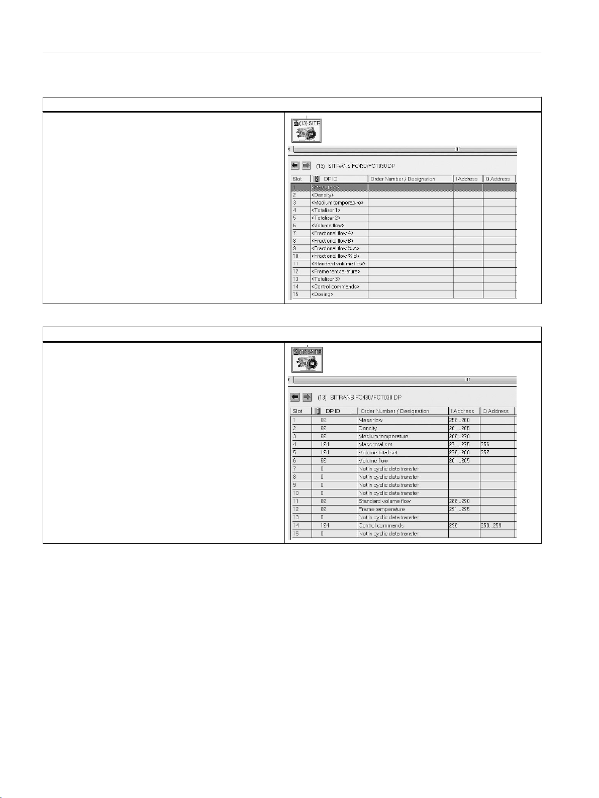
Communication
2.9 Cyclic data exchange
Slot configuration
The GSD file provides the possibilitiy to configure up to 15
modules.
Each module is linked to a specific process value or control
value in the device. It is recommended only to configure
modules that are processed by the master. If a process
value or a control value is not needed insert
data transfer
For Totalizer modules as Mass total, Volume total, Stand‐
ard volume total, Fraction A total or Fraction B total can
freely be selected in the slot that are assigned to Totalizer
1, 2, 3.
Default slot configuration
The GSD file provides the default slot configuration, as
shown to the right.
Slot 7,8,9 and 10 are specific for Fraction information.
Fraction information is only relevant if the device is ordered
with fraction option.
Not in cyclic
FCT030 Profibus (From firmware 4.0)
24 Function Manual, 06/2018, A5E39931906-AB
Page 25
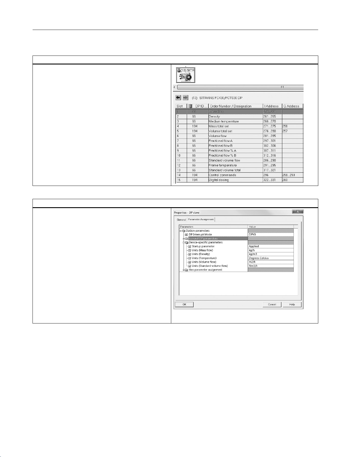
Device configuration – all modules selected
As shown to the right all modules are selected in the GSD
file.
Communication
2.9 Cyclic data exchange
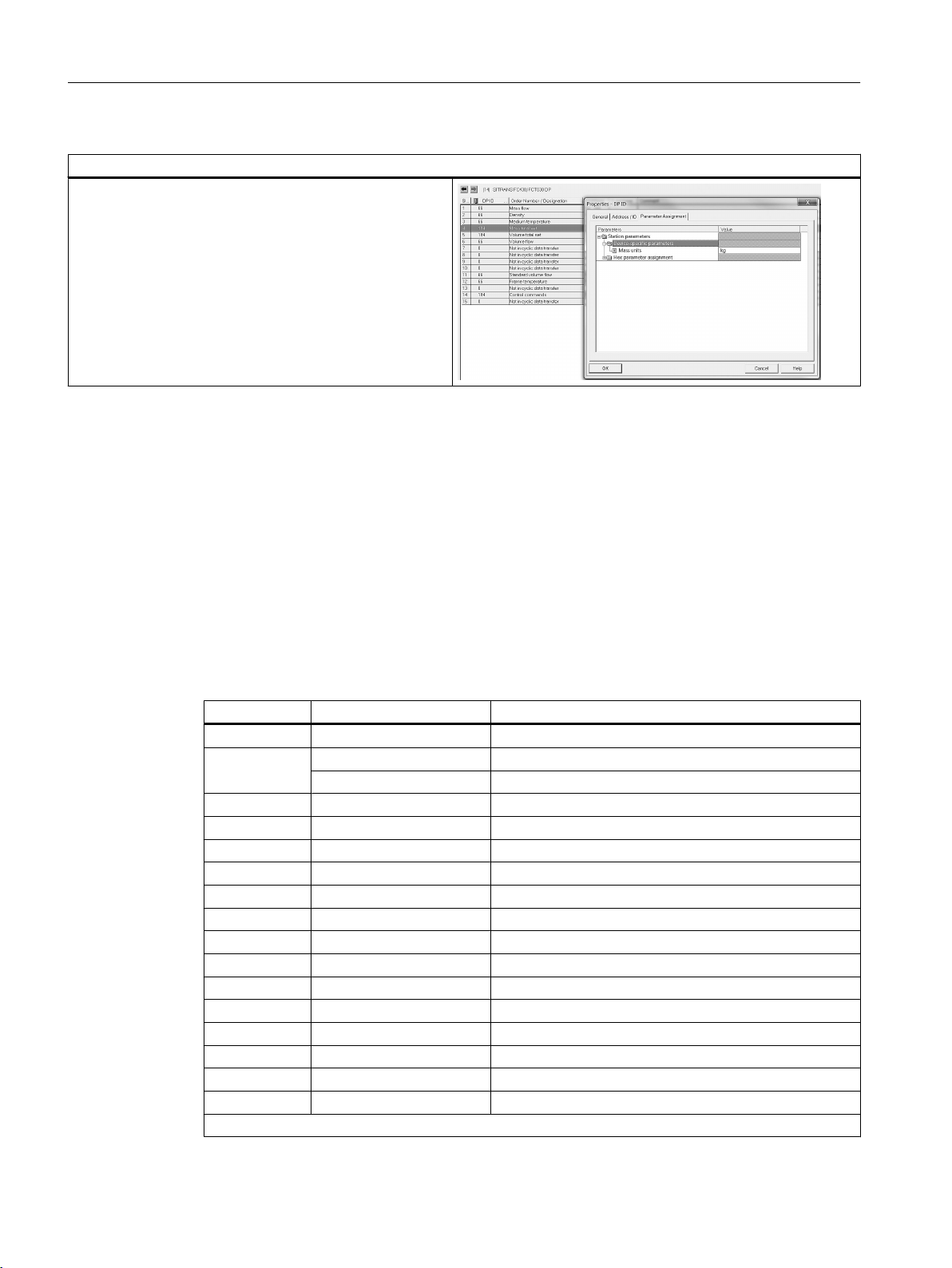
Default unit selection of process values
The device provides the possibility to select units for proc‐
ess values.Units are only valid for PROFIBUS, local HMI
display units will not be changed. Select object properties
of the transmitter icon and then Parameter assignment.
Click on device –specific parameters or configured by a pa‐
rameterization tool like SIMATIC PDM.
Startup parameter
Applied:
Selected units will overwrite the units that are selected in
the HMI display for PROFIBUS.
Ignored:
Selected units in the HMI display for PROFIBUS or config‐
ured by a parameterization tool like SIMATIC PDM will not
be overwritten.
FCT030 Profibus (From firmware 4.0)
Function Manual, 06/2018, A5E39931906-AB 25
Page 26
Communication
2.10 Acyclic communication
Default unit selection of Totalizers
The device provides the possibility to select units for each
totalizer type.
Units are only valid for PROFIBUS, local HMI display units
will not be changed.
Select object properties and then Parameter assignment.
Example is shown for Mass totalizer
2.10 Acyclic communication
Acyclic Addressing
Each parameter in a PROFIBUS slave is mapped to an address specified by slot and index.
The slot number refers to an array of data. The index tells you where in the array the data you
want starts.
Acyclic data
Slot Index Range Block
0 16…68 Physical block
1 16…37 Analog input block - Mass flow
68…138 Transducer block
2 16…37 Analog input block - Density
3 16…37 Analog input block - Medium Temperature
4 16…32 Totalizer block 1
5 16…32 Totalizer block 2
6 16…37 Analog input block - Volume Flow
7 16…37 Fraction Flow A block (Manufacturer Specific)
8 16…37 Fraction Flow B block (Manufacturer Specific)
9 16…37 Fraction Flow % A block (Manufacturer Specific)
10 16…37 Fraction Flow % B block (Manufacturer Specific)
11 16…37 Analog input block - Standard volume flow
12 16…37 Analog input block - Frame temperature
13 16…32 Totalizer block 3
14 16…19 Binary commands (Manufacturer Specific)
15 16…33 Dosing block (Manufacturer Specific)
30…255 Used for direct access of MODBUS registers.
FCT030 Profibus (From firmware 4.0)
26 Function Manual, 06/2018, A5E39931906-AB
Page 27

Table 2-4 SLOT 0, Physical Block
Communication
2.10 Acyclic communication
Index Parameter name Data type
[size]
16 BLOCK_OBJECT DS-32 Read only Constant block information
17 CURRENT_MODE Unsigned8 Read
22 TARGET_MODE Unsigned8 Read /
23 OrderID Visible‐
String(20)
24 Software_Revision Visible‐
String(16)
25 Hardware_Revision Visible‐
String(16)
26 VendorID Unsigned16 Read only Unsigned16 identifier of the product manufacturer
27 DEVICE_ID VisibleString
(16)
28 IM_Serial_Number Visible‐
String(16)
29 DIAGNOSIS OctetString(4) Read only Device global alarm information
31 IM_Tag_Location Visible‐
String(22)
Access Annotation
Follows the target mode
only
write
Read only Order ID no.
Read only String representation of the product firmware version
Read only String representation of the product hardware version
Read only Product name
Read only Serial number
Read /
write
8: Automatic
128: Out of service
Desired device mode that is taken over by the CURRENT‐
MODE parameter:
Coding:
8: Automatic
128: Out of service, sets all function blocks into out of service
Byte 0: Bits 0…7 reserved
Byte 1: Bits 0…2 reserved
Bit 3 warm start (restart)
Bit 4 cold start (application reset)
Bit 5 maintenance required
Bits 6…7 reserved
Byte 2: Bit 0 maintenance alarm
Bit 1 maintenance demanded
Bit 2 function check
Bit 3 invalid process conditions
Bit 4 update event
Bits 5…7 reserved
Byte 3: Bits 0…6 reserved
Bit 7 more information is available
Device location
FCT030 Profibus (From firmware 4.0)
Function Manual, 06/2018, A5E39931906-AB 27
Page 28

Communication
2.10 Acyclic communication
Index Parameter name Data type
[size]
32 IM_Revision_Coun‐
ter
33 IM_Profile_ID Unsigned16 Read only Fixed to 0x9700
34 IM_Profile_Specif‐
ic_Type
35 RESET Unsigned16 Read /
36 IM_DESCRIPTOR Visible‐
37 LANGUAGE Visible‐
38 IM_Date Visible‐
39 STARTUP_PAR‐
AM_VALIDITY
Unsigned16 Read only The device has parameters with attribute S (static) that are
Unsigned16 Read only -
String(54)
String(2)
String(16)
Unsigned8 Read only Provides information if the cyclic master has sent startup pa‐
Access Annotation
not changed by the process. This parameter will be incremen‐
ted at least by one if at least one static parameter has been
modified. This provides a check of the parameter revision. In
case of an overflow this parameter is set to 1 i.e. 0 is not used.
Valid Codes:
write
Read /
write
Read /
write
Read /
write
1: Application Reset:
Is the command for resetting a device to Profile
default values. The setting of the bus address is not affected.
2506: Restart
is the command for a restart of the device. All non-
volatile parameters re-main unchanged; all dynamic parame‐
ters are reset to their defaults.
2712: Communication Reset
The bus address is set to its default address; other
parameterization remains unchanged. The bus address is
changed immediately regardless if the device is in cyclic data
transfer state. The reset is not suspended up to a subsequent
power cycle / warm start. The No_Add_Chg_Flag correspond‐
ing to the Set_Slave_Add service is cleared.
2713: Application and Communication Reset
Combined Application Reset and Communication
Reset
54 character long description field
Language setting of the local user interface. The coding is
according Alpha-2 of ISO639. Available codes:
“en”
“de”
“it”
“fr”:
“es”
“zh”
Installation date of the device.
rameters that has been declared as valid to be taken to adjust
the device parameterization.
English
German
Italian
French
Spanish
Chinese
FCT030 Profibus (From firmware 4.0)
28 Function Manual, 06/2018, A5E39931906-AB
Page 29

Communication
2.10 Acyclic communication
Index Parameter name Data type
[size]
40 IDENT_NUM‐
BER_SELECTOR
41 BUS_ADDRESS Unsigned8 Read /
42 IDENT_NUMBER Unsigned16 Read only Current ident number that is used by the cyclic master when
43 BAUD RATE Unsigned8 Read only Shows the current used baud rate.
44 WRITE_PROTEC‐
TION
45 ALARM_DELAY Unsigned16 Read /
46 UP‐
DATE_EVENT_ACK
Unsigned8 Read only Specifies which ident number is used
Unsigned16 Read only Information about active parameter protection.
Unsigned8 Read /
Access Annotation
0: PA profile 4 specific ident number
0 : PA profile 4 specific ident number
1 : Device specific ident number (81CB/81CC)
127: Automatic adaption (default)
128: MASS6000 (8127/8128)
129: PA profile 3 specific (9700, 1 AI)
130: PA profile 3 specific (9701, 2 AI)
131: PA profile 3 specific (9702, 3 AI)
132: PA profile 3 specific (9742, 3 AI, 1 TOT)
PROFIBUS slave address that is currently set. Used by the
write
write
write
parameterization tool to create a complete snapshot of the
device parameterization.
in cyclic data exchange. If the device is not in cyclic data ex‐
change the default manufacturer specific ident number is re‐
turned.
0: 9.6 kbit/s
1: 19.2 kbit/s
2: 93.75 kbit/s
3: 187.5 kbit/s
4: 500 kbit/s
5: 1.5 Mbit/s
6: 3 Mbit/s
7: 6 Mbit/s
8: 12 Mbit/s
9: 31.25 kbit/s (MBP)
Note: The PA variant returns always code 9. The DP variant
does not support code 9 (31.25 kbit/s)
Bit 2: Password write protection enabled
Bit 15: Custody transfer mode enabled
A coming event is suppressed until the suppression time has
elapsed. This prevents alarm flooding.
Command to reset the update event flag in quality codes and
the DIAGNOSIS parameter in case that manual acknowledge
mode is enabled (UPDATE_EVENT_MODE)
FCT030 Profibus (From firmware 4.0)
Function Manual, 06/2018, A5E39931906-AB 29
Page 30

Communication
2.10 Acyclic communication
Index Parameter name Data type
[size]
47 UP‐
DATE_EVENT_MO
DE
48 NE107_COMMON OctetString(6) Read only Detailed information of the device, bitwise coded. Allows set‐
49 LINK_NE107_COM‐
MON
50 View_1 Read only Parameter to read the following block parameters at once:
51 View_2 Read /
52 View_3 Read /
Unsigned8 Read /
DS-69 Read /
Access Annotation
Holds the configuration for the behavior of the update event
write
write
write
write
flag in all status bytes
0: auto-acknowledge after 20 seconds.
1: manual acknowledge by means of parameter UP‐
DATE_EVENT_ACK
ting of diagnostic flags specified by the NAMUR recommen‐
dation NE107 comprising common device diagnostics. The
device type specific diagnostics are allocated to the respec‐
tive transducer block (module/submodule) that characterizes
the device type mainly.
Indicates / controls the reaction of the device on device spe‐
cific diagnostic events.
· BLOCK_OBJECT
· OrderID
· SOFTWARE_REVISION
· HARDWARE_REVISION
· VendorID
· DeviceID
· IM_Serial_Number
· IM_Profile_ID
· IM_Profile_Specific_Type
Parameter to read the following block parameters at once:
· CURRENT_MODE
· DIAGNOSIS
· IM_Revision_Counter
· STARTUP_PARAM_VALIDITY
· BUS_ADDRESS
· IDENT_NUMBER
· BAUD_RATE
· WRITE_PROTECTION
· NE107_COMMON
Parameter to read and write the following block parameters
at once:
· IM_Tag_Function
· IM_Tag_Location
· IM_Descriptor
· LANGUAGE
· IM_Date
· IDENT_NUMBER_SELECTOR
FCT030 Profibus (From firmware 4.0)
30 Function Manual, 06/2018, A5E39931906-AB
Page 31

Communication
2.10 Acyclic communication
Index Parameter name Data type
[size]
53 View_4 Read /
62 PARAMS_1_REG‐
ISTER
63 PARAMS_1_DATA Read /
64 PARAMS_2_REG‐
ISTER
65 PARAMS_2_DATA Read /
68 LIST_IDENT_NUM_
SUP
69 CURRENT_AC‐
CESS_LEVEL
70 DEFAULT_AC‐
CESS_LEVEL
71 LOGIN_USER Unsigned16 Read /
72 LOGIN_EXPERT Unsigned16 Read /
Read /
Read /
Unsigned16 Read only Provides information which ident numbers are supported by
Unsigned8 Read only Current access level of the acyclic connection. The access
Unsigned8 Read /
Access Annotation
write
write
write
write
write
write
write
write
Parameter to read and write the following block parameters
at once:
● TARGET_MODE
● ALARM_DELAY
● UPDATE_EVENT_MODE
● LINK_NE107_COMMON
32 bytes to define 16 MODBUS registers that are accessible
all with one read and/or write request to PARAMS_1_DATA
64 byte data field for parameters specified by PAR‐
AMS_1_REGISTER
64 bytes to define 32 MODBUS registers that are accessible
all with one read and/or write request to PARAMS_2_DATA
128 byte data field for parameters specified by PAR‐
AMS_2_REGISTER
This parameter is intentionally the double size of PAR‐
AMS_1_DATA. Some PROFIBUS components might still
have a frame length limit that does not allow the access of
larger data units. For these components PARAMS_1_DATA
can be used.
the device. This includes the profile GSD files.
level is handled for each acyclic connection.
2: Read only
3: User
4: Expert
Initial access level for an acyclic connection. See also access
control
2: Read only
3: User
Input of the end user PIN to change the current AC‐
CESS_LEVEL of the acyclic connection.
Reading this parameter indicates if User privilege is granted
(1) or not (0).
Input of the service user PIN to change the current AC‐
CESS_LEVEL of the acyclic connection
Reading this parameter indicates if User privilege is granted
(1) or not (0).
FCT030 Profibus (From firmware 4.0)
Function Manual, 06/2018, A5E39931906-AB 31
Page 32

Communication
2.10 Acyclic communication
Table 2-5 Slot 1: Analog Input block - Mass flow
Index Parameter name Data type Access Annotation
16 BLOCK_OBJECT DS-32 Read
only
17 CURRENT_MODE Unsigned8 Read
only
22 PROCESS_VALUE DS-101 Read
only
23 PROCESS_VAL‐
UE_UNITS
24 DAMPING Float32 Read /
25 SIMULATE DS-50 Read /
26 INPUT_SELECTOR Un‐
27 VIEW_1 Read
Manufacturer Specific
37 PROCESS_VAL‐
UE_UNITS_TEXT
Un‐
signed16
signed16
Visible‐
String(8)
Read
only
write
write
Read /
write
only
Read
only
Constant block information
8: Automatic
128: Out of service
Process value with quality code
Read-only copy of the transducer block unit setting
Low-pass filter of the input value. Value in seconds. Valid
range: 0…100 s
Possibility to simulate the PROCESS_VALUE parameter (in‐
cluding the quality code). This could be used to verify the
PLC program behavior.
Constant transducer reference information
Read-only parameter to read
● BLOCK_OBJECT
● CURRENT_MODE
● PROCESS_VALUE
● PROCESS_VALUE_UNITS
● DAMPING
● SIMULATE
Table 2-6 Slot 1: Transducer Block
Index Parameter name Data type Access Annotation
68 BLOCK_OBJECT DS-32 Read Constant block information
69 CURRENT_MODE Un‐
signed8
74 VOLUME_FLOW 101 Read Volume flow
Read Fixed to automatic (8)
FCT030 Profibus (From firmware 4.0)
32 Function Manual, 06/2018, A5E39931906-AB
Page 33

Index Parameter name Data type Access Annotation
75 VOL‐
UME_FLOW_UNITS
Un‐
signed16
Read /
Write
Volume flow units
The coding is according the PROFIBUS PA Profile specification:
1347: m³/s
1348: m³/min
1349: m³/h
1350: m³/d
1351: l/s
1352: l/min
1353: l/h
1354: l/d
1355: Ml/d
1356: ft³/s
1357: ft³/min
1358: ft³/h
1359: ft³/d
1362: gal/s
1363: gal/min
1364: gal/h
1365: gal/d
1366: Mgal/d
1367: i.gal/s
1368: i.gal/min
1369: i.gal/h
1370: i.gal/d
1371: BBL/s
1372: BBL/min
1373: BBL/h
1374: BBL/d
1448: µgal/s
1449: mgal/s
1450: kgal/s
1451: Mgal/s
1452: µgal/min
1453: mgal/min
1454: kgal/min
1455: Mgal/min
1456: µgal/h
1457: mgal/h
1458: kgal/h
1459: Mgal/h
1460: µgal/d
1461: mgal/d
1462: kgal/d
1463: µi.gal/s
Communication
2.10 Acyclic communication
FCT030 Profibus (From firmware 4.0)
Function Manual, 06/2018, A5E39931906-AB 33
Page 34

Communication
2.10 Acyclic communication
Index Parameter name Data type Access Annotation
1464: mi.gal/s
1465: ki.gal/s
1466: Mi.gal/s
1467: µi.gal/min
1468: mi.gal/min
1469: ki.gal/min
1470: Mi.gal/min
1471: µi.gal/h
1472: mi.gal/h
1473: ki.gal/h
1474: Mi.gal/h
1475: µi.gal/d
1476: mi.gal/d
1477: ki.gal/d
1478: Mi.gal/d
1479: µBBL/s
1480: mBBL/s
1481: kBBL/s
1482: MBBL/s
1483: µBBL/min
1484: mBBL/min
1485: kBBL/min
1486: MBBL/min
1487: µBBL/h D1942
1488: mBBL/h
1489: kBBL/h
1490: MBBL/h
1491: µBBL/d
1492: mBBL/d
1493: kBBL/d
1494: MBBL/d
1495: µm³/s
1496: mm³/s
1497: km³/s
1498: Mm³/s
1499: µm³/min
1500: mm³/min
1501: km³/min
1502: Mm³/min
1503: µm³/h
1504: mm³/h
1505: km³/h
1506: Mm³/h
1507: µm³/d
FCT030 Profibus (From firmware 4.0)
34 Function Manual, 06/2018, A5E39931906-AB
Page 35

Index Parameter name Data type Access Annotation
1508: mm³/d
1509: km³/d
1510: Mm³/d
1511: cm³/s
1512: cm³/min
1513: cm³/h
1514: cm³/d
1518: kl/min
1519: kl/h
1520: kl/d
1563: ml/min
1577: ml/s
1578: ml/h
1579: ml/d
1580: af/s
1581: af/min
1582: af/h
1583: af/d
1584: fl oz (US)/s
1585: fl oz (US)/min
1586: fl oz (US)/h
1587: fl oz (US)/d
1633: hl/s
1634: hl/min
1635: hl/h
1636: hl/d
1637: BBL/s
1638: BBL/min
1639: BBL/h
1640: BBL/d
1642: BBL/s
1643: BBL/min
1644: BBL/h
1645: BBL/d
1995: customized unit (
32768: bush/s
32769: bush/min
32770: bush/h
32771: bush/d
32772: yd³/s
32773: yd³/min
32774: yd³/h
32775: yd³/d
32776: in³/s
Communication
2.10 Acyclic communication
FCT030 Profibus (From firmware 4.0)
Function Manual, 06/2018, A5E39931906-AB 35
Page 36

Communication
2.10 Acyclic communication
Index Parameter name Data type Access Annotation
32777: in³/min
32778: in³/h
32779: in³/d
32780: Mft³/d
76 VOL‐
UME_FLOW_LO_LI
MIT
77 VOL‐
UME_FLOW_HI_LIM‐
IT
78 MASS_FLOW 101 Read Mass flow
79 MASS_FLOW_UNITSUn‐
80 MASS_FLOW_LO_LI
MIT
Float32 Read Volume flow low limit
Float32 Read Volume flow high limit
Read /
signed16
Float32 Read Mass flow low limit
Write
Mass flow units:
The coding is according the PROFIBUS PA Profile specification:
1318: g/s
1319: g/min
1320: g/h
1321: g/d
1322: kg/s
1323: kg/min
1324: kg/h
1325: kg/d
1326: t/s
1327: t/min
1328: t/h
1329: t/d
1330: lb/s
1331: lb/min
1332: lb/h
1333: lb/d
1334: STon/s
1335: STon/min
1336: STon/h
1337: STon/d
1338: T/s
1339: T/min
1340: T/h
1341: T/d
1606: oz/s
1607: oz/min
1608: oz/h
1609: oz/d
1995: customized unit
FCT030 Profibus (From firmware 4.0)
36 Function Manual, 06/2018, A5E39931906-AB
Page 37

Index Parameter name Data type Access Annotation
81 MASS_FLOW_HI_LI
MIT
82 DENSITY 101 Read Process value
83 DENSITY_UNITS Un‐
84 DENSITY_LO_LIMIT Float32 Read Fixed to 0.0
85 DENSITY_HI_LIMIT Float32 Read Fixed to 5000
86 TEMPERATURE 101 Read Media temperature
87 TEMPERA‐
TURE_UNITS
88 TEMPERA‐
TURE_LO_LIMIT
89 TEMPERA‐
TURE_HI_LIMIT
98 LOW_FLOW_CUT‐
OFF
99 FLOW_DIRECTION Un‐
Float32 Read Mass flow high limit
Read /
signed16
Un‐
signed16
Float32 Read Media temperature flow low limit
Float32 Read Media temperature high limit
Float32 Read /
signed8
Write
Read /
Write
Write
Read /
Write
Density unit
The coding is according the PROFIBUS PA Profile specification:
1097: kg/m³
1098: Mg/m³
1099: kg/dm³
1100: g/cm³
1101: g/m³
1102: t/m³
1103: kg/l
1104: g/ml
1105: g/l
1106: lb/in³
1107: lb/ft³
1108: lb/gal
1109: STon/yd³
1430: lb/i.gal
1558: mg/l
1559: µg/l
1564: mg/dm³
1566: mg/m³
1995: customized unit
Temperature unit that is used by temperature values
Coding:
1000: K
1001: °C
1002: °F
1003: °R
Mass flow low-flow cut-off filter
Assigns an arbitrary positive or negative sign to the measured
PV value.
Coding:
0: positive
1: negative
Communication
2.10 Acyclic communication
FCT030 Profibus (From firmware 4.0)
Function Manual, 06/2018, A5E39931906-AB 37
Page 38

Communication
2.10 Acyclic communication
Index Parameter name Data type Access Annotation
100 NE107_CORIOLIS Octet‐
String(3)
101 LINK_NE107_CORI‐
OLIS
112 VIEW_1 Read Parameter to read the following block parameters at once:
113 VIEW_2 Read /
123 FRAME_TEMPERA‐
124 STANDARD_VOL‐
Manufacturer Specif‐
ic
TURE
UME_FLOW
DS-69 Read /
101 Read Process value in TEMPERATURE_UNITS
101 Read Process value in STANDARD_VOLUME_FLOW_UNITS
Read
Write
Write
● BLOCK_OBJECT
● CURRENT_MODE
● MASS_FLOW
● MASS_FLOW_UNITS
● MASS_FLOW_LO_LIMIT
● MASS_FLOW_HI_LIMIT
● DENSITY
● DENSITY_UNITS
● DENSITY_LO_LIMIT
● DENSITY_HI_LIMIT
● TEMPERATURE
● TEMPERATURE_UNITS
● TEMPERATURE_LO_LIMIT
● TEMPERATURE_HI_LIMIT
● LOW_FLOW_CUTOFF
● FLOW_DIRECTION
● NE_107_CORIOLIS
● LINK_NE107_CORIOLIS
Parameter to read and write the following block parameters at
once:
● MASS_FLOW_UNITS
● DENSITY_UNITS
● TEMPERATURE_UNITS
● LOW_FLOW_CUTOFF
● FLOW_DIRECTION
● LINK_NE107_CORIOLIS
FCT030 Profibus (From firmware 4.0)
38 Function Manual, 06/2018, A5E39931906-AB
Page 39

Index Parameter name Data type Access Annotation
125 STANDARD_VOL‐
UME_FLOW_UNITS
126 FRAC‐
TION_FLOW_A
127 FRAC‐
TION_FLOW_B
Un‐
signed16
101 Read
101 Read
Read /
Write
Standard volume flow unit
The coding is according the PROFIBUS PA Profile specification:
1588: Nm³/s
1360: Sft³/min
1361: Sft³/h
1589: Nm³/min
1590: Nm³/h
1591: Nm³/d
1592: Nl/s
1593: Nl/min
1594: Nl/h
1595: Nl/d
1596: Sm³/s
1597: Sm³/min
1598: Sm³/h
1599: Sm³/d
1600: Sl/s
1601: Sl/min
1602: Sl/h
1603: Sl/d
1604: Sft³/s
1605: Sft³/d
1995: customized unit
Communication
2.10 Acyclic communication
FCT030 Profibus (From firmware 4.0)
Function Manual, 06/2018, A5E39931906-AB 39
Page 40

Communication
2.10 Acyclic communication
Index Parameter name Data type Access Annotation
128 FRAC‐
TION_FLOW_UNITS
Un‐
signed16
Read /
Write
Selected unit for fractional mass flow value that affects values
accessed via the PROFIBUS fieldbus interface.
The coding is according the PROFIBUS PA Profile specification:
1318: g/s
1319: g/min
1320: g/h
1321: g/d
1322: kg/s
1323: kg/min
1324: kg/h
1325: kg/d
1326: t/s
1327: t/min
1328: t/h
1329: t/d
1330: lb/s
1331: lb/min
1332: lb/h
1333: lb/d
1334: STon/s
1335: STon/min
1336: STon/h
1337: STon/d
1338: T/s
1339: T/min
1340: T/h
1341: T/d
1606: oz/s
1607: oz/min
1608: oz/h
1609: oz/d
1995: customized unit
Selected unit for fractional volume flow value that affects values
accessed via the PROFIBUS fieldbus interface.
The coding is according the PROFIBUS PA Profile specification:
1347: m³/s
1348: m³/min
1349: m³/h
1350: m³/d
1351: l/s
1352: l/min
1353: l/h
1354: l/d
1355: Ml/d
FCT030 Profibus (From firmware 4.0)
40 Function Manual, 06/2018, A5E39931906-AB
Page 41

Index Parameter name Data type Access Annotation
1356: ft³/s
1357: ft³/min
1358: ft³/h
1359: ft³/d
1362: gal/s
1363: gal/min
1364: gal/h
1365: gal/d
1366: Mgal/d
1367: i.gal/s
1368: i.gal/min
1369: i.gal/h
1370: i.gal/d
1371: BBL/s
1372: BBL/min
1373: BBL/h
1374: BBL/d
1448: µgal/s
1449: mgal/s
1450: kgal/s
1451: Mgal/s
1452: µgal/min
1453: mgal/min
1454: kgal/min
1455: Mgal/min
1456: µgal/h
1457: mgal/h
1458: kgal/h
1459: Mgal/h
1460: µgal/d
1461: mgal/d
1462: kgal/d
1463: µi.gal/s
1464: mi.gal/s
1465: ki.gal/s
1466: Mi.gal/s
1467: µi.gal/min
1468: mi.gal/min
1469: ki.gal/min
1470: Mi.gal/min
1471: µi.gal/h
1472: mi.gal/h
1473: ki.gal/h
1474: Mi.gal/h
Communication
2.10 Acyclic communication
FCT030 Profibus (From firmware 4.0)
Function Manual, 06/2018, A5E39931906-AB 41
Page 42

Communication
2.10 Acyclic communication
Index Parameter name Data type Access Annotation
1475: µi.gal/d
1476: mi.gal/d
1477: ki.gal/d
1478: Mi.gal/d
1479: µBBL/s
1480: mBBL/s
1481: kBBL/s
1482: MBBL/s
1483: µBBL/min
1484: mBBL/min
1485: kBBL/min
1486: MBBL/min
1487: µBBL/h D1942
1488: mBBL/h
1489: kBBL/h
1490: MBBL/h
1491: µBBL/d
1492: mBBL/d
1493: kBBL/d
1494: MBBL/d
1495: µm³/s
1496: mm³/s
1497: km³/s
1498: Mm³/s
1499: µm³/min
1500: mm³/min
1501: km³/min
1502: Mm³/min
1503: µm³/h
1504: mm³/h
1505: km³/h
1506: Mm³/h
1507: µm³/d
1508: mm³/d
1509: km³/d
1510: Mm³/d
1511: cm³/s
1512: cm³/min
1513: cm³/h
1514: cm³/d
1518: kl/min
1519: kl/h
1520: kl/d
1563: ml/min
FCT030 Profibus (From firmware 4.0)
42 Function Manual, 06/2018, A5E39931906-AB
Page 43

Index Parameter name Data type Access Annotation
1577: ml/s
1578: ml/h
1579: ml/d
1580: af/s
1581: af/min
1582: af/h
1583: af/d
1584: fl oz (US)/s
1585: fl oz (US)/min
1586: fl oz (US)/h
1587: fl oz (US)/d
1633: hl/s
1634: hl/min
1635: hl/h
1636: hl/d
1637: BBL/s
1638: BBL/min
1639: BBL/h
1640: BBL/d
1642: BBL/s
1643: BBL/min
1644: BBL/h
1645: BBL/d
1995: customized unit (see PID_CUSTOM_STRING_VOL‐
UME_FLOW and PID_CUSTOM_FACTOR_VOLUME_FLOW)
32768: bush/s
32769: bush/min
32770: bush/h
32771: bush/d
32772: yd³/s
32773: yd³/min
32774: yd³/h
32775: yd³/d
32776: in³/s
32777: in³/min
32778: in³/h
32779: in³/d
32780: Mft³/d
129 FRAC‐
TION_FLOW_PCT_A
130 FRAC‐
TION_FLOW_PCT_B
101 Read Percentage fraction process value
101 Read Percentage fraction process value
Communication
2.10 Acyclic communication
FCT030 Profibus (From firmware 4.0)
Function Manual, 06/2018, A5E39931906-AB 43
Page 44

Communication
2.10 Acyclic communication
Index Parameter name Data type Access Annotation
131 FRAC‐
TION_FLOW_PCT_
UNITS
132 LOW_VOL‐
UME_FLOW_CUT‐
OFF
133 CUS‐
TOM_UNIT_FAC‐
TOR_MASS_FLOW
134 CUSTOM_UNIT_LA‐
BEL_MASS_FLOW
135 CUS‐
TOM_UNIT_FAC‐
TOR_VOL‐
UME_FLOW
136 CUSTOM_UNIT_LA‐
BEL_VOL‐
UME_FLOW
137 CUS‐
TOM_UNIT_FAC‐
TOR_DENSITY
138 CUSTOM_UNIT_LA‐
BEL_DENSITY
139 CUS‐
TOM_UNIT_FAC‐
TOR_STAND‐
ARD_VOL‐
UME_FLOW
140 CUSTOM_UNIT_LA‐
BEL_STAND‐
ARD_VOL‐
UME_FLOW
Un‐
signed16
Float32 Read /
Float32 Read /
Visible‐
String(8)
Float32 Read /
Visible‐
String(8)
Float32 Read /
Visible‐
String(8)
Float32 Read /
Visible‐
String(8)
Read /
Write
Write
Write
Read /
Write
Write
Read /
Write
Write
Read /
Write
Write
Read /
Write
Unit code that affects FRACTION_FLOW_PCT_A and FRAC‐
TION_FLOW_PCT_B.
Coding:
1342: %
1428: °proof
Low-flow cut-off filter setting for volume flow
Define a mass flow factor for the custom units mass flow
Define a name for the custom units mass flow
Define a mass flow factor for the custom units volume flow
Define a name for the custom units volume flow
Define a mass flow factor for the custom units Density flow
Define a name for the custom units Density flow
Define a mass flow factor for the custom units standard volume
flow
Define a name for the custom units standard volume flow
Table 2-7 Slot 2: Analog Input block - Density
In‐
Parameter Name Data
dex
16 BLOCK_OBJECT DS-32 Read only Constant block information
17 CURRENT_MODE Un‐
22 PROCESS_VAL‐UEDS-101 Read only Process value with quality code
23 PROCESS_VAL‐
UE_UNITS
Type
signed8
Un‐
sign‐
ed16
Access Annotation
Read only Follows the target mode of the Physical Block
8: Automatic
128: Out of service
Read only Read-only copy of the transducer block unit setting
FCT030 Profibus (From firmware 4.0)
44 Function Manual, 06/2018, A5E39931906-AB
Page 45

In‐
Parameter Name Data
dex
24 DAMPING Float32 Read /
25 SIMULATE DS-50 Read /
26 VIEW_1 Read only Read-only parameter to read
Manufacturer Specific
36 PROCESS_VAL‐
UE_UNITS_TEXT
Table 2-8 Slot 3: Analog Input block - Medium temperature
Type
Visible‐
String(8
)
Access Annotation
Low-pass filter of the input value. Value in seconds. Valid range: 0…100
write
write
Read only
s
Possibility to simulate the PROCESS_VAUE parameter (including the
quality code). This could be used to verify the PLC program behavior.
● CURRENT MODE
● DENSITY FLOW
● DENSITY UNITS
● DAMPING
● SIMULATE
Communication
2.10 Acyclic communication
Index Parameter Name Data Type Access Annotation
16 BLOCK_OBJECT DS-32 Read
only
17 CURRENT_MODE Unsigned8 Read
only
22 PROCESS_VALUE DS-101 Read
only
23 PROCESS_VAL‐
UE_UNITS
24 DAMPING Float32 Read /
25 SIMULATE DS-50 Read /
26 VIEW_1 Read
Manufacturer Specific
36 PROCESS_VAL‐
UE_UNITS_TEXT
Un‐
signed16
Visible‐
String(8)
Read
only
write
write
only
Read
only
Constant block information
Follows the target mode of the Physical Block
8: Automatic
128: Out of service
Process value with quality code
Read-only copy of the transducer block unit setting
Low-pass filter of the input value. Value in seconds. Valid
range: 0…100 s
Possibility to simulate the PROCESS_VAUE parameter (in‐
cluding the quality code). This could be used to verify the
PLC program behavior.
Read-only parameter to read
● CURRENT_MODE
● MEDIUM TEMPERATURE
● MEDIUM TEMPERATURE UNITS
● DAMPING
● SIMULATE
FCT030 Profibus (From firmware 4.0)
Function Manual, 06/2018, A5E39931906-AB 45
Page 46

Communication
2.10 Acyclic communication
Table 2-9 Slot 1: Totalizer block 1
In‐
Parameter Name Data
dex
16 BLOCK_OBJECT DS-32 Read only Constant block information used to identify the block type
17 CURRENT_MODE Un‐
22 TOTAL 101 Read only 32-bit floating point process value with quality code. The value follows
Type
signed8
Access Annotation
Read only Set to “Out of service” if the TARGET_MODE parameter of the Physical
Block is set to “Out of service”.
Available modes:
8: Automatic
128: Out of Service
TOTAL_UNITS.
TOTAL and TOTAL_DOUBLE are always “on pair” i.e. both showing the
same totalized value but with a different precision.
FCT030 Profibus (From firmware 4.0)
46 Function Manual, 06/2018, A5E39931906-AB
Page 47

In‐
Parameter Name Data
dex
23 TOTAL_UNITS Un‐
Type
sign‐
ed16
Access Annotation
Read /
write
Influences the TOTAL,TOTAL_DOUBLE and PRESET_TOT value.
The INPUT_SELECTOR defines the available physical unit codes that are
allowed e.g. INPUT_SELECTOR is set to mass flow, the TOTAL_UNITS
only accepts mass units.
Available Mass units:
1088: kg
1089: g
1090: mg
1091: Mg
1092: t
1093: oz
1094: lb
1095: STon
1096: T
1567: ct
1568: lb (tr)
1569: oz (tr)
1995: customized unit
Available Volume units:
1034: m³
1035: dm³
1036: cm³
1037: mm³
1038: l
1039: cl
1040: ml
1041: hl
1042: in³
1043: ft³
1044: yd³
1045: mile³
1048: gal
1046: pint
1047: quart
1049: i.gal
1050: bush
1051: BBL
1052: BBL (liq)
1517: kl
1570: fl oz (US)
1572: af
Communication
2.10 Acyclic communication
FCT030 Profibus (From firmware 4.0)
Function Manual, 06/2018, A5E39931906-AB 47
Page 48

Communication
2.10 Acyclic communication
In‐
Parameter Name Data
dex
24 SET_TOT Un‐
25 MODE_TOT Un‐
26 FAIL_TOT Un‐
27 PRESET_TOT Float32 Read /
28 INPUT_SELEC‐
TOR
29 SIMULATE DS-50 Read /
30 TOTAL_DOUBLE 106 Read only 64-bit floating point process value with quality code. The value follows
Type
signed8
signed8
signed8
Un‐
signed8
Access Annotation
1641: BBL (fed)
1995: customized unit
Available Standard volume units:
1053: Sft³
1573: Nm³
1574: Nl
1575: Sm³
1576: Sl
1995: customized unit
Read /
write
Read /
write
Read /
write
write
Read /
write
write
1: RESET; assign value „0“ to Totalizer
2: PRESET; assign value of PRESET_TOT to Totalizer
3: HOLD; totalization stopped
4: TOTALIZE; „normal“ operation of the Totalizer
0: FORWARD AND BACKWARD; totalization of positive and negative
incoming flowrate
1: FORWARD; totalization of positive incoming rate values only.
2: BACKWARD; totalization of negative incoming rate values only.
0: RUN; totalization is continued using the input values despite the BAD
status. The status is ignored.
1: HOLD; totalization is stopped during occurrence of BAD status of in‐
coming
values.
2: MEMORY; totalization is continued based on the last incoming value
with GOOD status before the first occurrence of BAD status.
This 32-bit floating point value is used as a preset for the internal value of
the FB algorithm. The value gets effective if using the SET function. This
value follows TOTAL_UNITS.
0: Mass flow
1: Volume flow
2: Standard volume flow
3…127: reserved
128: Fraction Flow A
129: Fraction Flow B
Simulation
TOTAL_UNITS.
TOTAL and TOTAL_DOUBLE are always “on pair” i.e. both showing the
same totalized value but with a different precision.
FCT030 Profibus (From firmware 4.0)
48 Function Manual, 06/2018, A5E39931906-AB
Page 49

Communication
2.10 Acyclic communication
In‐
Parameter Name Data
dex
31 VIEW_1 Read only Read-only parameter to read the following block parameters at once
32 VIEW_2 Read /
Manufacturer Specific
41 TO‐
TAL_UNITS_TEXT
Type
Visible‐
String(8
)
Access Annotation
● CURRENT_MODE
● TOTAL_DOUBLE
● TOTAL_UNITS
● SET_TOT
● MODE_TOT
● FAIL_TOT
● PRESET_TOT
● INPUT_SELECTOR
Parameter to read and write the following block parameters at once
write
Read only Textual unit representation of the current TOTAL_UNITS parameter set‐
● SET_TOT
● MODE_TOT
● FAIL_TOT
● PRESET_TOT
● INPUT_SELECTOR
tings.
Table 2-10 Slot 5: Totalizer block 2
In‐
Parameter Name Data
dex
16 BLOCK_OBJECT DS-32 Read only Constant block information used to identify the block type
17 CURRENT_MODE Un‐
22 TOTAL 101 Read only 32-bit floating point process value with quality code. The value follows
Type
signed8
Access Annotation
Read only Set to “Out of service” if the TARGET_MODE parameter of the Physical
Block is set to “Out of service”.
Available modes:
8: Automatic
128: Out of Service
TOTAL_UNITS.
TOTAL and TOTAL_DOUBLE are always “on pair” i.e. both showing the
same totalized value but with a different precision.
FCT030 Profibus (From firmware 4.0)
Function Manual, 06/2018, A5E39931906-AB 49
Page 50

Communication
2.10 Acyclic communication
In‐
Parameter Name Data
dex
23 TOTAL_UNITS Un‐
Type
sign‐
ed16
Access Annotation
Read /
write
Influences the TOTAL,TOTAL_DOUBLE and PRESET_TOT value.
The INPUT_SELECTOR defines the available physical unit codes that are
allowed e.g. INPUT_SELECTOR is set to mass flow, the TOTAL_UNITS
only accepts mass units.
Available Mass units:
1088: kg
1089: g
1090: mg
1091: Mg
1092: t
1093: oz
1094: lb
1095: STon
1096: T
1567: ct
1568: lb (tr)
1569: oz (tr)
1995: customized unit
Available Volume units:
1034: m³
1035: dm³
1036: cm³
1037: mm³
1038: l
1039: cl
1040: ml
1041: hl
1042: in³
1043: ft³
1044: yd³
1045: mile³
1048: gal
1046: pint
1047: quart
1049: i.gal
1050: bush
1051: BBL
1052: BBL (liq)
1517: kl
1570: fl oz (US)
1572: af
FCT030 Profibus (From firmware 4.0)
50 Function Manual, 06/2018, A5E39931906-AB
Page 51

Communication
2.10 Acyclic communication
In‐
Parameter Name Data
dex
24 SET_TOT Un‐
25 MODE_TOT Un‐
26 FAIL_TOT Un‐
27 PRESET_TOT Float32 Read /
28 INPUT_SELEC‐
TOR
29 SIMULATE DS-50 Read /
30 TOTAL_DOUBLE 106 Read only 64-bit floating point process value with quality code. The value follows
Type
signed8
signed8
signed8
Un‐
signed8
Access Annotation
1641: BBL (fed)
1995: customized unit
Available Standard volume units:
1053: Sft³
1573: Nm³
1574: Nl
1575: Sm³
1576: Sl
1995: customized unit
Read /
write
Read /
write
Read /
write
write
Read /
write
write
1: RESET; assign value „0“ to Totalizer
2: PRESET; assign value of PRESET_TOT to Totalizer
3: HOLD; totalization stopped
4: TOTALIZE; „normal“ operation of the Totalizer
0: FORWARD AND BACKWARD; totalization of positive and negative
incoming flowrate
1: FORWARD; totalization of positive incoming rate values only.
2: BACKWARD; totalization of negative incoming rate values only.
0: RUN; totalization is continued using the input values despite the BAD
status. The status is ignored.
1: HOLD; totalization is stopped during occurrence of BAD status of in‐
coming
values.
2: MEMORY; totalization is continued based on the last incoming value
with GOOD status before the first occurrence of BAD status.
This 32-bit floating point value is used as a preset for the internal value of
the FB algorithm. The value gets effective if using the SET function. This
value follows TOTAL_UNITS.
0: Mass flow
1: Volume flow
2: Standard volume flow
3…127: reserved
128: Fraction Flow A
129: Fraction Flow B
TOTAL_UNITS.
TOTAL and TOTAL_DOUBLE are always “on pair” i.e. both showing the
same totalized value but with a different precision.
FCT030 Profibus (From firmware 4.0)
Function Manual, 06/2018, A5E39931906-AB 51
Page 52

Communication
2.10 Acyclic communication
In‐
Parameter Name Data
dex
31 VIEW_1 Read only Read-only parameter to read the following block parameters at once
32 VIEW_2 Read /
Manufacturer Specific
41 TO‐
TAL_UNITS_TEXT
Type
Visible‐
String(8
)
Access Annotation
● CURRENT_MODE
● TOTAL_DOUBLE
● TOTAL_UNITS
● SET_TOT
● MODE_TOT
● FAIL_TOT
● PRESET_TOT
● INPUT_SELECTOR
Parameter to read and write the following block parameters at once
write
Read only Textual unit representation of the current TOTAL_UNITS parameter set‐
● SET_TOT
● MODE_TOT
● FAIL_TOT
● PRESET_TOT
● INPUT_SELECTOR
tings.
Table 2-11 Slot 6: Analog Input block - Volume flow
Index Parameter Name Data Type Access Annotation
16 BLOCK_OBJECT DS-32 Read
only
17 CURRENT_MODE Unsigned8 Read
only
22 PROCESS_VALUE DS-101 Read
only
23 PROCESS_VAL‐
UE_UNITS
24 DAMPING Float32 Read /
25 SIMULATE DS-50 Read /
26 VIEW_1 Read
Un‐
signed16
Read
only
write
write
only
Constant block information
Follows the target mode of the Physical Block
8: Automatic
128: Out of service
Process value with quality code
Read-only copy of the transducer block unit setting
Low-pass filter of the input value. Value in seconds. Valid
range: 0…100 s
Possibility to simulate the PROCESS_VAUE parameter (in‐
cluding the quality code). This could be used to verify the
PLC program behavior.
Read-only parameter to read
● CURRENT_MODE
● VOLUME FLOW
● VOLUME FLOW UNITS
● DAMPING
● SIMULATE
FCT030 Profibus (From firmware 4.0)
52 Function Manual, 06/2018, A5E39931906-AB
Page 53

Index Parameter Name Data Type Access Annotation
Manufacturer Specific
36 PROCESS_VAL‐
UE_UNITS_TEXT
Table 2-12 Slot 7: Analog Input block - Fractional flow A block
Index Parameter Name Data Type Access Annotation
16 BLOCK_OBJECT DS-32 Read
17 CURRENT_MODE Unsigned8 Read
22 PROCESS_VALUE DS-101 Read
23 PROCESS_VAL‐
UE_UNITS
24 DAMPING Float32 Read /
25 SIMULATE DS-50 Read /
26 VIEW_1 Read
Manufacturer Specific
36 PROCESS_VAL‐
UE_UNITS_TEXT
Visible‐
String(8)
Un‐
signed16
Visible‐
String(8)
Read
only
only
only
only
Read
only
write
write
only
Read
only
Constant block information
Follows the target mode of the Physical Block
8: Automatic
128: Out of service
Process value with quality code
Read-only copy of the transducer block unit setting
Low-pass filter of the input value. Value in seconds. Valid
range: 0…100 s
Possibility to simulate the PROCESS_VALUE parameter (in‐
cluding the quality code). This could be used to verify the
PLC program behavior.
Read-only parameter to read
● CURRENT_MODE
● FRACTIONAL FLOW A
● FRACTIONAL FLOW A UNITS
● DAMPING
● SIMULATE
Communication
2.10 Acyclic communication
Table 2-13 Slot 8: Analog Input block - Fractional flow B block
Index Parameter Name Data Type Access Annotation
16 BLOCK_OBJECT DS-32 Read
only
17 CURRENT_MODE Unsigned8 Read
only
22 PROCESS_VALUE DS-101 Read
only
23 PROCESS_VAL‐
UE_UNITS
24 DAMPING Float32 Read /
FCT030 Profibus (From firmware 4.0)
Function Manual, 06/2018, A5E39931906-AB 53
Un‐
signed16
Read
only
write
Constant block information
Follows the target mode of the Physical Block
8: Automatic
128: Out of service
Process value with quality code
Read-only copy of the transducer block unit setting
Low-pass filter of the input value. Value in seconds. Valid
range: 0…100 s
Page 54

Communication
2.10 Acyclic communication
Index Parameter Name Data Type Access Annotation
25 SIMULATE DS-50 Read /
write
26 VIEW_1 Read
only
Manufacturer Specific
36 PROCESS_VAL‐
UE_UNITS_TEXT
Table 2-14 Slot 9: Analog Input block - Fractional flow % A block
Index Parameter Name Data Type Access Annotation
16 BLOCK_OBJECT DS-32 Read
17 CURRENT_MODE Unsigned8 Read
22 PROCESS_VALUE DS-101 Read
23 PROCESS_VAL‐
UE_UNITS
24 DAMPING Float32 Read /
25 SIMULATE DS-50 Read /
26 VIEW_1 Read
Manufacturer Specific
36 PROCESS_VAL‐
UE_UNITS_TEXT
Visible‐
String(8)
Un‐
signed16
Visible‐
String(8)
Read
only
only
only
only
Read
only
write
write
only
Read
only
Possibility to simulate the PROCESS_VAUE parameter (in‐
cluding the quality code). This could be used to verify the
PLC program behavior.
Read-only parameter to read
● CURRENT_MODE
● FRACTIONAL FLOW B
● FRACTIONAL FLOW B UNITS
● DAMPING
● SIMULATE
Constant block information
Follows the target mode of the Physical Block
8: Automatic
128: Out of service
Process value with quality code
Read-only copy of the transducer block unit setting
Low-pass filter of the input value. Value in seconds. Valid
range: 0…100 s
Possibility to simulate the PROCESS_VAUE parameter (in‐
cluding the quality code). This could be used to verify the
PLC program behavior.
Read-only parameter to read
● CURRENT_MODE
● FRACTIONAL FLOW % A
● FRACTIONAL FLOW % A UNITS
● DAMPING
● SIMULATE
FCT030 Profibus (From firmware 4.0)
54 Function Manual, 06/2018, A5E39931906-AB
Page 55

Table 2-15 Slot 10: Analog Input block - Fractional flow % B block
Index Parameter Name Data Type Access Annotation
16 BLOCK_OBJECT DS-32 Read
only
17 CURRENT_MODE Unsigned8 Read
only
22 PROCESS_VALUE DS-101 Read
only
23 PROCESS_VAL‐
UE_UNITS
24 DAMPING Float32 Read /
25 SIMULATE DS-50 Read /
26 VIEW_1 Read
Manufacturer Specific
36 PROCESS_VAL‐
UE_UNITS_TEXT
Un‐
signed16
Visible‐
String(8)
Read
only
write
write
only
Read
only
Constant block information
Follows the target mode of the Physical Block
8: Automatic
128: Out of service
Process value with quality code
Read-only copy of the transducer block unit setting
Low-pass filter of the input value. Value in seconds. Valid
range: 0…100 s
Possibility to simulate the PROCESS_VAUE parameter (in‐
cluding the quality code). This could be used to verify the
PLC program behavior.
Read-only parameter to read
● CURRENT_MODE
● FRACTIONAL FLOW % B
● FRACTIONAL FLOW % B UNITS
● DAMPING
● SIMULATE
Communication
2.10 Acyclic communication
Table 2-16 Slot 11: Analog Input block - Standard volume flow
Index Parameter Name Data Type Access Annotation
16 BLOCK_OBJECT DS-32 Read
only
17 CURRENT_MODE Unsigned8 Read
only
22 PROCESS_VALUE DS-101 Read
only
23 PROCESS_VAL‐
UE_UNITS
24 DAMPING Float32 Read /
25 SIMULATE DS-50 Read /
Un‐
signed16
Read
only
write
write
Constant block information
Follows the target mode of the Physical Block
8: Automatic
128: Out of service
Process value with quality code
Read-only copy of the transducer block unit setting
Low-pass filter of the input value. Value in seconds. Valid
range: 0…100 s
Possibility to simulate the PROCESS_VAUE parameter (in‐
cluding the quality code). This could be used to verify the
PLC program behavior.
FCT030 Profibus (From firmware 4.0)
Function Manual, 06/2018, A5E39931906-AB 55
Page 56

Communication
2.10 Acyclic communication
Index Parameter Name Data Type Access Annotation
26 VIEW_1 Read
only
Manufacturer Specific
36 PROCESS_VALUE_
UNITS_TEXT
Table 2-17 Slot 12: Analog Input block - Frame temperature
Index Parameter Name Data Type Access Annotation
16 BLOCK_OBJECT DS-32 Read
17 CURRENT_MODE Unsigned8 Read
22 PROCESS_VALUE DS-101 Read
23 PROCESS_VAL‐
UE_UNITS
24 DAMPING Float32 Read /
25 SIMULATE DS-50 Read /
26 VIEW_1 Read
Manufacturer Specific
36 PROCESS_VAL‐
UE_UNITS_TEXT
Visible‐
String (8)
Un‐
signed16
Visible‐
String(8)
Read
only
only
only
only
Read
only
write
write
only
Read
only
Read-only parameter to read
● CURRENT_MODE
● STANDARD VOLUME FLOW
● STANDARD VOLUME FLOW UNITS
● DAMPING
● SIMULATE
Constant block information
Follows the target mode of the Physical Block
8: Automatic
128: Out of service
Process value with quality code
Read-only copy of the transducer block unit setting
Low-pass filter of the input value. Value in seconds. Valid
range: 0…100 s
Possibility to simulate the PROCESS_VAUE parameter (in‐
cluding the quality code). This could be used to verify the
PLC program behavior.
Read-only parameter to read
● CURRENT_MODE
● FRAME TEMPERATURE
● FRAME TEMPERATURE UNITS
● DAMPING
● SIMULATE
FCT030 Profibus (From firmware 4.0)
56 Function Manual, 06/2018, A5E39931906-AB
Page 57

Communication
2.10 Acyclic communication
Table 2-18 Slot 13: Totalizer block 3
In‐
Parameter Name Data
dex
16 BLOCK_OBJECT DS-32 Read only Constant block information used to identify the block type
17 CURRENT_MODE Un‐
22 TOTAL 101 Read only 32-bit floating point process value with quality code. The value follows
Type
signed8
Access Annotation
Read only Set to “Out of service” if the TARGET_MODE parameter of the Physical
Block is set to “Out of service”.
Available modes:
8: Automatic
128: Out of Service
TOTAL_UNITS.
TOTAL and TOTAL_DOUBLE are always “on pair” i.e. both showing the
same totalized value but with a different precision.
FCT030 Profibus (From firmware 4.0)
Function Manual, 06/2018, A5E39931906-AB 57
Page 58

Communication
2.10 Acyclic communication
In‐
Parameter Name Data
dex
23 TOTAL_UNITS Un‐
Type
sign‐
ed16
Access Annotation
Read /
write
Influences the TOTAL,TOTAL_DOUBLE and PRESET_TOT value.
The INPUT_SELECTOR defines the available physical unit codes that are
allowed e.g. INPUT_SELECTOR is set to mass flow, the TOTAL_UNITS
only accepts mass units.
Available Mass units:
1088: kg
1089: g
1090: mg
1091: Mg
1092: t
1093: oz
1094: lb
1095: STon
1096: T
1567: ct
1568: lb (tr)
1569: oz (tr)
1995: customized unit
Available Volume units:
1034: m³
1035: dm³
1036: cm³
1037: mm³
1038: l
1039: cl
1040: ml
1041: hl
1042: in³
1043: ft³
1044: yd³
1045: mile³
1048: gal
1046: pint
1047: quart
1049: i.gal
1050: bush
1051: BBL
1052: BBL (liq)
1517: kl
1570: fl oz (US)
1572: af
FCT030 Profibus (From firmware 4.0)
58 Function Manual, 06/2018, A5E39931906-AB
Page 59

Communication
2.10 Acyclic communication
In‐
Parameter Name Data
dex
24 SET_TOT Un‐
25 MODE_TOT Un‐
26 FAIL_TOT Un‐
27 PRESET_TOT Float32 Read /
28 INPUT_SELEC‐
TOR
29 SIMULATE DS-50 Read /
30 TOTAL_DOUBLE 106 Read only 64-bit floating point process value with quality code. The value follows
Type
signed8
signed8
signed8
Un‐
signed8
Access Annotation
1641: BBL (fed)
1995: customized unit
Available Standard volume units:
1053: Sft³
1573: Nm³
1574: Nl
1575: Sm³
1576: Sl
1995: customized unit
Read /
write
Read /
write
Read /
write
write
Read /
write
write
1: RESET; assign value „0“ to Totalizer
2: PRESET; assign value of PRESET_TOT to Totalizer
3: HOLD; totalization stopped
4: TOTALIZE; „normal“ operation of the Totalizer
0: FORWARD AND BACKWARD; totalization of positive and negative
incoming flowrate
1: FORWARD; totalization of positive incoming rate values only.
2: BACKWARD; totalization of negative incoming rate values only.
0: RUN; totalization is continued using the input values despite the BAD
status. The status is ignored.
1: HOLD; totalization is stopped during occurrence of BAD status of in‐
coming values.
2: MEMORY; totalization is continued based on the last incoming value
with GOOD status before the first occurrence of BAD status.
This 32-bit floating point value is used as a preset for the internal value of
the FB algorithm. The value gets effective if using the SET function. This
value follows TOTAL_UNITS.
0: Mass flow
1: Volume flow
2: Standard volume flow
3…127: reserved
128: Fraction Flow A
129: Fraction Flow B
130…255: reserved
TOTAL_UNITS.
TOTAL and TOTAL_DOUBLE are always “on pair” i.e. both showing the
same totalized value but with a different precision.
FCT030 Profibus (From firmware 4.0)
Function Manual, 06/2018, A5E39931906-AB 59
Page 60

Communication
2.10 Acyclic communication
In‐
Parameter Name Data
dex
31 VIEW_1 Read only Read-only parameter to read the following block parameters at once
32 VIEW_2 Read /
Manufacturer Specific
41 TO‐
TAL_UNITS_TEXT
Type
Visible‐
String(8
)
Access Annotation
● CURRENT_MODE
● TOTAL_DOUBLE
● TOTAL_UNITS
● SET_TOT
● MODE_TOT
● FAIL_TOT
● PRESET_TOT
● INPUT_SELECTOR
Parameter to read and write the following block parameters at once
write
Read only Textual unit representation of the current TOTAL_UNITS parameter set‐
● SET_TOT
● MODE_TOT
● FAIL_TOT
● PRESET_TOT
● INPUT_SELECTOR
tings.
Table 2-19 Slot 14: Control commands (Manufacturer Specific)
In‐
Parameter Name Data
dex
16 BLOCK_OBJECT DS-32 Read only Constant block information
17 CURRENT_MODE Un‐
Type
signed8
Access Annotation
Read only Follows the target mode of the Physical Block. In out of service no com‐
mand is processed.
8: Automatic
128: Out of service
FCT030 Profibus (From firmware 4.0)
60 Function Manual, 06/2018, A5E39931906-AB
Page 61

In‐
Parameter Name Data
dex
18 COMMAND Un‐
19 COMMAND_STA‐
TUS
Type
sign‐
ed8(2)
Un‐
signed8
Access Annotation
Read /
write
Read only Command Status
Command invocation
Byte 0: Command
Bit 0: Start zero point adjustment
Bit 1: Freeze process values
Bit 2: Force outputs
Byte 1: Command Validity Mask
Bit coded information to indicate which bit or bits are valid to be processed
by the device.
Bit 0: process “Start zero point adjustment” command
Bit 1: process “Freeze process values” command
Bit 2: process “Force outputs command”
The command bit is only processed if the corresponding mask bit is set.
Otherwise the command information is ignored.
The concurrent access could happen if an acyclic master sets up a write
request while the cyclic master is connected and provides also command
data. The acyclic write request is processed but could be overwritten by
the cyclic master if the validity bit in scope is set.
Bit 0: Zero point adjustment processing
Bit 1: Process values are frozen
Bit 2: Outputs are forced
Communication
2.10 Acyclic communication
Table 2-20 Dosing block, SLOT 15
In‐
Parameter Name Data
dex
16 BLOCK_OBJECT DS-32 Read only Constant block information
17 CURRENT_MODE Un‐
18 BATCH_STATE Un‐
19 BATCH_COM‐
MAND
FCT030 Profibus (From firmware 4.0)
Function Manual, 06/2018, A5E39931906-AB 61
Type
signed8
signed8
Un‐
signed8
Access Annotation
Read only Fixed to automatic (8)
Read only 0: batch stopped
1: batch running
2: batch paused
3: cleaning (all valves are set to "open valve")
Read /
write
Used to control a dosing cycle:
1: start batch
2: stop batch
3: pause batch
4: resume batch
5: start cleaning
Reading this parameter returns 0
Page 62

Communication
2.10 Acyclic communication
In‐
Parameter Name Data
dex
20 MODE Un‐
21 INPUT_SELEC‐
TOR
22 AMOUNT_DONE DS-101 Read only Current amount that is totalized since the start of the batch cycle. Includes
23 AMOUNT_RE‐
MAINING
24 RECIPE_ID Un‐
25 RECIPE_NAME String16 Read /
26 RECIPE_TAR‐
GET_AMOUNT
27 REC‐
IPE_AMOUNT_UN
IT
28 - - 29 RECIPE_
FIXED_COMPEN‐
SATION
Analog dosing
30 ANALOG_OUT‐
PUT
31 RECIPE_
CUR‐
RENT_CLOSED
32 RECIPE_
CURRENT_PAR‐
TIAL_OPEN
Type
signed8
Un‐
signed8
DS-101 Read only Amount that is missing to complete the current batch
signed8
Float32 Read /
Un‐
sign‐
ed16
Float32 Read /
DS-101 Read only Calculated set point for analog valve
Float32 Read /
Float32 Read /
Access Annotation
Read /
write
Read /
write
Read /
write
write
write
Read /
write
Batching Mode
0: off, batching disabled
1: 1-stage batching
2: 2-stage batching
3: analog batching
Batch input selection:
0: Mass Flow
1: Volume Flow
4: Standard Volume Flow
5: Fraction Flow Media A
6: Fraction Flow Media B
a quality code
Active recipe that specifies the used parameter set.
Valid range 1…5
The recipe´s name
The recipe´s target amount. Follows the unit setting by RECIPE_TAR‐
GET_AMOUNT
Unit code that influences the AMOUNT_DONE, AMOUNT_REMAINING
and RECIPE_TARGET_AMOUNT values
-
Define the fixed pre-stop value. The value is subtracted from 'Amount' to
write
write
write
compensate for application delays in closing the valves.
Current level that is used in analog batching mode when the
analog valve shall be closed.
Define current level to partly close the analog valve
FCT030 Profibus (From firmware 4.0)
62 Function Manual, 06/2018, A5E39931906-AB
Page 63

In‐
Parameter Name Data
dex
33 RECIPE_
CUR‐
RENT_FULLY_OP
EN
Digital dosing
34 DIGITAL_OUT‐
PUT_1
35 DIGITAL_OUT‐
PUT_2
Type
Float32 Read /
DS-102 Read only Calculated set point for the digital valve 1
DS-102 Read only Calculated set point for the digital valve 2
Access Annotation
write
2.11 Access Control
If the flowmeter is ordered with custody transfer (CT), and the CT write protection DIP switch
is ON, the device will reject all write requests to CT parameters independent of the access
control. See the operation manual for further CT information and write protected parameters
Communication
2.11 Access Control
Define current level to fully open the analog valve.
● Each acyclic PROFIBUS connection has an access level that can be changed by providing
PIN information via the parameters USER_PIN and / or EXPERT_PIN
● Each parameter has a protection level assigned that specifies the required access level to
modify the parameter via an acyclic PROFIBUS connection.
● If the access level of the acyclic PROFIBUS connection is smaller than the protection level
of the parameter that is desired to be modified, then the attempt to modify the parameter
is rejected by the device.
The following access levels are provided:
Access level Description
READ ONLY Having this access level, the acyclic PROFIBUS master is not able to modify
the device configuration (setup parameters). The PROFIBUS master is only
able to execute commands, e.g. start dosing and reset totalizers.
USER Having this access level, the PROFIBUS master is able to modify a subset of
the device configuration. The PROFIBUS master has to provide the correct
end user password to the parameter USER_PIN to reach this access level.
The initiator is a “normal” user in the plant not having access to critical parts
of the configuration.
EXPERT Having this access level, the PROFIBUS master is able to modify the config‐
uration of the device. The PROFIBUS master has to provide the correct serv‐
ice user password to the parameter EXPERT_PIN to reach this access level.
The initiator is either a service user at the plant (not Siemens service person‐
nel) or Siemens service personnel.
FCT030 Profibus (From firmware 4.0)
Function Manual, 06/2018, A5E39931906-AB 63
Page 64

Communication
2.12 Alarm, error, and system messages
2.12 Alarm, error, and system messages
2.12.1 Introduction
The PROFIBUS slave has the capability of sending diagnostic data. The diagnostic data is
hierarchically organized.
● Device status
● General faults ans conditions
● Alarm status (1 to 10)
2.12.2 Diagnosis Response
A PROFIBUS master is able to request diagnosis information from the slave using the
diagnosis service. The following table shows the content of the diagnosis response sent from
the device upon a request from the master.
Table 2-21 Diagnosis Response
Byte Element Name Description
10…13 Device status Device status
Restart
Application reset
Maintenance required
Maintenance alarm
Maintenance demanded
Function check
Out of specification
Parameter update
Extension available
NE107 diagnostic
FCT030 Profibus (From firmware 4.0)
64 Function Manual, 06/2018, A5E39931906-AB
Page 65

2.12 Alarm, error, and system messages
Byte Element Name Description
14…19 General faults and
faults conditions
Detailed alarm status
23…26 ALARM_STATUS_1 Detailed alarm status information
27…30 ALARM_STATUS_2
31…34 ALARM_STATUS_3
35…38 ALARM_STATUS_4
39…42 ALARM_STATUS_5
43…46 ALARM_STATUS_6
47…50 ALARM_STATUS_7
51…54 ALARM_STATUS_8
55…58 ALARM_STATUS_9
59…62 ALARM_STATUS_10
Sensor element exciter faulty
Error in evaluation electronics
Error in internal energy supply
Error in sensor element
Error in actuator element
Faulty installation e.g. dead space
Parameter setting error
Signal path broken or short cut
Overloading Wrong polarity of aux power
Maximum line length exceeded
Corrosion/abrasion by medium
Fouling on sensor element
Auxil medium missing or insufficient
Wear reserve used up (operation)
Wear reserve used up (wear)
Error in peripherals
Electromag interference too high
Temperature of medium too high
Ambient temperature too high
Vibration/Impact load too high
Auxiliary power range off-spec
Auxiliary medium missing
Excessive temperature shock
Deviation from measurement
Humidity in electronics area
Medium in electronics area
Mechanical damage
Communication error
Foreign material in electro area
Communication
FCT030 Profibus (From firmware 4.0)
Function Manual, 06/2018, A5E39931906-AB 65
Page 66

Communication
2.12 Alarm, error, and system messages
FCT030 Profibus (From firmware 4.0)
66 Function Manual, 06/2018, A5E39931906-AB
Page 67

Cable specifications
Recommended cable types
The PROFIBUS standard defines two variations of the bus cable: Cable type A and cable type
B. It is recommended to use cable Type A in all new installations.
Both types have cable shielding that guarantees adequate protection from electromagnetic
interference and thus the most reliable data transfer.
Table 3-1 Cable type A specifications
Type A
Cable structure twisted pair, individual shield
Wire size 0.8 mm2 (AWG 18)
Loop resistance (DC) 44 Ω/km
Impedance at 31.25 kHz 100 Ω ± 20%
Attenuation at 39 kHz 3 dB/km
Capacitive asymmetry 2 nF/km
Envelope delay distortion (7.9 to 39 kHz) 1.7 μs/km
Shield coverage 90%
Max. cable length (inc. spurs >1 m) 1900 m (6233 ft)
3
Siemens provides a suitable cable for non-hazardous area with following order number 6XV1830-0EH10
Overall cable length
The overall cable length is made up of the length of the main cable and the length of all spurs
(>1 m/3.28 ft).
The maximum network expansion depends on the type of ignition protection and the cable
specifications.
Note
If repeaters are used the maximum allowed cable length is doubled. Max. three repeaters are
permitted between user and master.
PROFIBUS transmission rate (kBit/s) Cable length
9.6 1200 400
19.2 1200 400
45,45 1200 400
93,75 1200 400
[m] [ft]
FCT030 Profibus (From firmware 4.0)
Function Manual, 06/2018, A5E39931906-AB 67
Page 68

Cable specifications
PROFIBUS transmission rate (kBit/s) Cable length
[m] [ft]
187,5 1000 3300
500 400 1300
1500 200 650
3000 100 330
6000 100 330
12000 100 330
FCT030 Profibus (From firmware 4.0)
68 Function Manual, 06/2018, A5E39931906-AB
Page 69

Definitions
4
Acyclic Data – data read over the acyclic communication channel, and this data could take
several bus scans to be read. The total amount of time that this process takes is random and
therefore acyclic.
Baud Rate – the speed of the network in bits per second.
Class 1 Master – a type of device on a PROFIBUS network and the traditional master in process
control systems. Refers to a Distributed Control System (DCS) or Programmable Logic
Controller (PLC).
Class 2 Master – a type of device on a PROFIBUS network and the traditional engineering
work station. An example of a class 2 master is SIMATIC PDM.
Cyclic Data – data that is read in every bus scan. It’s the input and output data used for control
and is time sensitive.
Deterministic – the knowledge that something is going to occur with a fixed time period. This
is a requirement of advanced control systems.
EDD – the Electronic Device Description is a collection of text files describing all the acyclic
data in a field device and how to read and write them. EDDs are used by configuration software
such as SIMATIC PDM to configure field instruments.
EDDL – Electronic Device Description Language is the language that EDDs are written in.
EDDL is an international standard defined in IEC 61804-2 and IEC 61804-3.
Ethernet – Ethernet is a type of physical layer defined in the IEEE 802.3 standard used for
communications in a local area network.
FDT – Field Device Tool is standard program interface (software) for configuring field devices.
FDT uses Device Type Managers to program field devices. FDT software is an alternative to
EDD based software such as SIMATIC PDM.
FDI – Field Device Integration is the evolution of FDT and EDD technology. It is for configuration
of field devices and is based on OPC-UA (Object Linking and Embedding for Process Control
– Unified Architecture) and EDD technology.
FF – Foundation Fieldbus is a digital protocol used to configure and troubleshoot field
instruments.
FISCO – Fieldbus Intrinsic Safe Concept. A standard that makes it easy to place FISCO
approved instruments into zone 0 and above environments.
FNICO – Fieldbus Non-Incendive Concept. A similar standard to FISCO. It is makes it easy to
place FISCO approved instruments into zone 2 environments.
Full-duplex – Full-duplex refers to a communication link that is bi-directional allowing for both
devices to talk and listen at the same time.
GSD – General System Data (or Generic Slave Description) is a text file in PROFIBUS and a
XML file in PROFINET defining all the protocol information and cyclic data of a field device. It
is used by the network configuration software to identify the slave and to set up the data
exchanged between the master and the slave during cyclic data exchange. GSD was also
originally the German acronym for Gerätestammdaten.
FCT030 Profibus (From firmware 4.0)
Function Manual, 06/2018, A5E39931906-AB 69
Page 70

Definitions
Gateway – A gateway is a device that joins two different networks together. For example, to
connect a Modbus device to a PROFIBUS network, a Profibus to Modbus gateway is needed.
HART – Highway Addressable Remote Transducer is an industrial protocol used to configure
and troubleshoot field instruments. It is often considered a transition between the 4–20mA
technology and full digital technology since it uses both.
IEC – International Electrical Congress is an international standards organization committed
to creating and maintaining international and open standards for use in the electrical industries.
I/O-Controller – A type of device on a PROFNET network and the traditional master in process
control systems. Refers to a Distributed Control System (DCS) or Programmable Logic
Controller (PLC).
I/O-Device – A type of device on PROFINET that provides input data or realizes output data
into the real world.
I/O-Supervisor – A type of device on a PROFINET network and the traditional engineering
work station. An example is SIMATIC PDM.
ISA – Instrumentation, Systems, and Automation Society is a world wide organization that
develops standards, certifies industry professionals, provides education and training,
publishes books and technical articles, and hosts conferences and exhibitions.
Interchangeability – The ability to switch from one vendor’s device to another vendor’s similar
device. Interchangeability is a key benefit of PROFIBUS Profile standard.
Intrinsically Safe – An intrinsically safe device keeps the voltage and current low enough so
that it cannot generate a spark of sufficient energy to ignite the gas/particles in the atmosphere
making it safe for use.
Interoperability – The ability to connect different devices from different manufacturers on the
same network and have them work correctly. This is a core strength of PROFIBUS.
Managed Switch – A type of switch that provides additional advanced diagnostics.
Master – A type of device on PROFIBUS that controls communication to slave devices. One
PROFIBUS network can have several Masters on it, and they share communications by using
a token ring protocol.
MBP – Manchester encoded Bus Powered. This is the physical layer defined in IEC-61158-2
that is used for PROFIBUS PA
MBP-IS – This is the same physical layer as MBP, with the addition of power limiters on the
power supply so that the power draws will not exceed those defined for intrinsically safe
operation.
Modem – This is a device that translates a signal from one transmission technology to another.
For example an optical modem converts an electrical signal into light and then back again.
Physical Layer – Refers to medium used to get the ones and zeros from point A to point B.
This layer of the protocol is all about wires and voltage and current levels.
PROFIBUS – Process Fieldbus. Automation communication protocol designed to meet all
industrial and process communication needs.
PROFIBUS DP – DP stands for Decentralized Peripheral and was designed for remote input
output devices. This forms the core protocol of PROFIBUS. If PROFIBUS were a book, it would
be called PROFIBUS DP.
FCT030 Profibus (From firmware 4.0)
70 Function Manual, 06/2018, A5E39931906-AB
Page 71

Definitions
PROFidrive – A chapter in the PROFIBUS book or PROFINET book that adds functions to the
core protocol for high speed drive applications.
PROFIsafe – A chapter in the PROFIBUS book or PROFINET book that adds functions to the
core protocol for safety applications.
PROFIBUS PA – A chapter in the PROFIBUS book or PROFINET book that adds functions to
the core protocol for process control applications. PA refers to Process Automation.
PROFINET – A second book by the same authors as PROFIBUS. PROFINET is an Ethernet
based protocol that makes use of many sections of the PROFIBUS protocol and make optimal
use of Ethernet.
Profile – A profile is a standardization of a field device from the bus point of view. It defines the
output and the core device parameters.
Protocol – Refers to a set of rules. In industrial communications, it simply refers to a set of
rules defining how something is done. For example, how to get information from point A to
point B. Since one set of rules can be made up of many different sets of rules, one protocol
can be made up of different sub-protocols.
Proxy – A type of gateway defined in PROFINET which, aside from joining two networks
together, also defines how the date is set as well. Think of it as a very easy-to-use gateway.
Slave – A type of device on PROFIBUS that will only talk on the network after a Master device
has requested information.
Switch – A device that directs the traffic on an Ethernet network. It reads the incoming packet
and directs it to the correct port where the target device is located.
TCO – Total Cost of Ownership is a financial term used in asset management referring to all
the costs associated with ownership. In process automation, it is the sum of the cost of the
device plus the cost of commissioning plus the cost of maintaining the device.
Token Ring – A type of protocol using a virtual token that is passed from master to master.
The master can only talk on the bus when it has the token. When it is has finished talking on
the bus, the master passes the token onto another master.
FCT030 Profibus (From firmware 4.0)
Function Manual, 06/2018, A5E39931906-AB 71
Page 72

Definitions
FCT030 Profibus (From firmware 4.0)
72 Function Manual, 06/2018, A5E39931906-AB
Page 73

Index
D
Document history, 5
Documentation
Edition, 5
T
Technical data
Cable specifications, 67
Transducer Block 1, 32
FCT030 Profibus (From firmware 4.0)
Function Manual, 06/2018, A5E39931906-AB 73
Page 74

Index
FCT030 Profibus (From firmware 4.0)
74 Function Manual, 06/2018, A5E39931906-AB
 Loading...