

Page 1

SITRANS F
Coriolis Flowmeters
FCT030 Modbus (From firmware
4.0)
Introduction
1
Function Manual
Communication
Commissioning
MODBUS commands
Definitions
2
3
4
A
06/2018
A5E39931813-AB
Page 2
Legal information
Warning notice system
This manual contains notices you have to observe in order to ensure your personal safety, as well as to prevent
damage to property. The notices referring to your personal safety are highlighted in the manual by a safety alert
symbol, notices referring only to property damage have no safety alert symbol. These notices shown below are
graded according to the degree of danger.
DANGER
indicates that death or severe personal injury will result if proper precautions are not taken.
WARNING
indicates that death or severe personal injury may result if proper precautions are not taken.
CAUTION
indicates that minor personal injury can result if proper precautions are not taken.
NOTICE
indicates that property damage can result if proper precautions are not taken.
If more than one degree of danger is present, the warning notice representing the highest degree of danger will be
used. A notice warning of injury to persons with a safety alert symbol may also include a warning relating to property
damage.
Qualified Personnel
The product/system described in this documentation may be operated only by personnel qualified for the specific
task in accordance with the relevant documentation, in particular its warning notices and safety instructions. Qualified
personnel are those who, based on their training and experience, are capable of identifying risks and avoiding
potential hazards when working with these products/systems.
Proper use of Siemens products
Note the following:
WARNING
Siemens products may only be used for the applications described in the catalog and in the relevant technical
documentation. If products and components from other manufacturers are used, these must be recommended or
approved by Siemens. Proper transport, storage, installation, assembly, commissioning, operation and
maintenance are required to ensure that the products operate safely and without any problems. The permissible
ambient conditions must be complied with. The information in the relevant documentation must be observed.
Trademarks
All names identified by ® are registered trademarks of Siemens AG. The remaining trademarks in this publication
may be trademarks whose use by third parties for their own purposes could violate the rights of the owner.
Disclaimer of Liability
We have reviewed the contents of this publication to ensure consistency with the hardware and software described.
Since variance cannot be precluded entirely, we cannot guarantee full consistency. However, the information in
this publication is reviewed regularly and any necessary corrections are included in subsequent editions.
Siemens AG
Division Process Industries and Drives
Postfach 48 48
90026 NÜRNBERG
GERMANY
Document order number: A5E39931813
Ⓟ 05/2018 Subject to change
Copyright © Siemens AG 2018.
All rights reserved
Page 3

Table of contents
1 Introduction...................................................................................................................................................7
1.1 Purpose of this documentation.................................................................................................7
1.2 Document history.....................................................................................................................7
1.3 Product compatibility................................................................................................................8
2 Communication.............................................................................................................................................9
2.1 System integration...................................................................................................................9
2.2 System configuration................................................................................................................9
2.3 System wiring.........................................................................................................................12
2.4 Connecting.............................................................................................................................14
2.4.1 Connecting the Modbus (CH1)...............................................................................................14
3 Commissioning...........................................................................................................................................17
3.1 General requirements............................................................................................................17
3.2 Operating via SIMATIC PDM.................................................................................................17
3.3 Functions in SIMATIC PDM...................................................................................................17
3.4 Commissioning steps.............................................................................................................17
3.5 Initial Setup............................................................................................................................17
3.6 Adding a device to communication network...........................................................................20
3.7 Configuring a new device.......................................................................................................21
3.8 Wizard - Quick Start via PDM................................................................................................22
3.9 Wizard - Zero Point adjustment..............................................................................................29
3.10 Changing parameter settings using SIMATIC PDM...............................................................30
3.11 Parameters accessed via drop-down menus.........................................................................31
4 MODBUS commands.................................................................................................................................33
4.1 Modbus addressing model.....................................................................................................33
4.2 Modbus communication.........................................................................................................33
4.3 Coil configuration...................................................................................................................35
4.4 Modbus register mapping.......................................................................................................36
4.5 Integer byte order...................................................................................................................38
4.6 Float transmission..................................................................................................................38
4.7 Float byte order......................................................................................................................39
4.8 Modbus function codes..........................................................................................................39
FCT030 Modbus (From firmware 4.0)
Function Manual, 06/2018, A5E39931813-AB 3
Page 4

Table of contents
4.9 Access control........................................................................................................................40
4.10 Modbus holding registers tables............................................................................................41
4.10.1 Modbus holding registers tables (intro)..................................................................................41
4.10.2 Process values.......................................................................................................................42
4.10.3 Totalizers................................................................................................................................44
4.10.4 Units.......................................................................................................................................46
4.10.5 Setup......................................................................................................................................58
4.10.5.1 Sensor settings......................................................................................................................58
4.10.5.2 Density...................................................................................................................................59
4.10.5.3 Aerated flow...........................................................................................................................61
4.10.5.4 Zero point adjustment............................................................................................................62
4.10.5.5 Quality codes for process values...........................................................................................64
4.10.5.6 Process values.......................................................................................................................69
4.10.5.7 Totalizers................................................................................................................................74
4.10.5.8 Inputs and outputs..................................................................................................................80
4.10.5.9 Date and time.......................................................................................................................122
4.10.5.10 Local display........................................................................................................................123
4.10.5.11 Selectable values dependent on the view type....................................................................133
4.10.5.12 Process value filter masks...................................................................................................135
4.10.6 Maintenance and diagnostics...............................................................................................135
4.10.6.1 Identification.........................................................................................................................136
4.10.7 Diagnostic events.................................................................................................................139
4.10.7.1 Active events........................................................................................................................139
4.10.7.2 Diagnostic log.......................................................................................................................143
4.10.7.3 Alarm items..........................................................................................................................145
4.10.8 Diagnostics...........................................................................................................................152
4.10.8.1 Device diagnostics...............................................................................................................152
4.10.8.2 Temperature monitoring.......................................................................................................152
4.10.8.3 Dosing..................................................................................................................................153
4.10.8.4 Inputs and outputs................................................................................................................165
4.10.8.5 Peak values..........................................................................................................................170
4.10.9 Characteristics.....................................................................................................................174
4.10.9.1 Product.................................................................................................................................174
4.10.9.2 Transmitter...........................................................................................................................174
4.10.10 SensorFlash.........................................................................................................................175
4.10.10.1 SensorFlash.........................................................................................................................175
4.10.10.2 Data logging.........................................................................................................................176
4.10.11 Simulation............................................................................................................................177
4.10.11.1 Inputs and outputs................................................................................................................177
4.10.11.2 Process values.....................................................................................................................183
4.10.11.3 Alarms..................................................................................................................................184
4.10.12 Audit trail..............................................................................................................................186
4.10.12.1 Operating time......................................................................................................................186
4.10.12.2 Parameter change log..........................................................................................................186
4.10.12.3 FW update change log.........................................................................................................188
4.10.12.4 Device reset.........................................................................................................................188
4.10.13 Communication....................................................................................................................189
4.10.13.1 Service channel....................................................................................................................189
4.10.14 Security................................................................................................................................189
4.10.14.1 Access management............................................................................................................189
FCT030 Modbus (From firmware 4.0)
4 Function Manual, 06/2018, A5E39931813-AB
Page 5

Table of contents
A Definitions.................................................................................................................................................191
A.1 Definitions............................................................................................................................191
Index.........................................................................................................................................................195
FCT030 Modbus (From firmware 4.0)
Function Manual, 06/2018, A5E39931813-AB 5
Page 6

Table of contents
FCT030 Modbus (From firmware 4.0)
6 Function Manual, 06/2018, A5E39931813-AB
Page 7

Introduction
1.1 Purpose of this documentation
This manual contains all information needed to integrate the process instruments into a
communications network. The manual is aimed at control system designers, system
integrators, instrument engineers.
In order to operate safety and for more detailed information you need the product specific
manual. Available for download from Flow documentation (http://www.siemens.com/
flowdocumentation).
This manual applies to the SITRANS FCT030 transmitter Modbus version only. The FCT030
transmitter can be used in combination with the following sensors:
Mass 2100
FC300
FCS400 and FSC300
In order to operate a Coriolis flow meter, you also need Operating Instructions. See Flow
documentation (http://www.siemens.com/flowdocumentation)
1
1.2 Document history
The following table shows major changes in the documentation compared to the previous
edition.
The most important changes in the documentation when compared with the respective
previous edition are given in the following table.
Edition Note
06/2018 Second edition
06/2017 First edition
Use the device to measure process medium in accordance with the information in the
Operating Instructions.
Note
Use in a domestic environment
This Class A Group 1 equipment is intended for use in industrial areas.
In a domestic environment this device may cause radio interference.
FCT030 Modbus (From firmware 4.0)
Function Manual, 06/2018, A5E39931813-AB 7
Page 8

Introduction
1.3 Product compatibility
1.3 Product compatibility
Edition Remarks Product compatibility Compatibility of device integration package
06/2017 First revision HW revision 03
Compact FW revision 4.xx.xx-xx
Remote FW revision 4.xx.xx-xx
Service channel: SIMATIC
V8.2 Service Pack 1 or later
Modbus: SIMATIC V8.2 Serv‐
ice Pack 1 or later
HART: SIMATIC V8.2 Serv‐
ice Pack 1 or later
HART: SITRANS DTM V4.1 5.00.xx-xx
HART: AMS Device manager
V12
PROFIBUS: SIMATIC V8.2
Service Pack 1 or later
PROFIBUS : SITRANS DTM
V4.1
5.00.xx-xx
5.00.xx-xx
5.00.xx-xx
5.00.xx-xx
1.00.xx-xx
1.00.xx-xx
FCT030 Modbus (From firmware 4.0)
8 Function Manual, 06/2018, A5E39931813-AB
Page 9

Communication
56
0DVWHU
0HDVXULQJ
GHYLFH
2.1 System integration
This chapter provides information on how to integrate the device in a point-to-point or multidrop
Modbus RTU network in non-hazardous or hazardous areas. Many details of network design
are beyond the scope of these operating instructions. The points below provide an overview
of the major design criteria. For further details contact Siemens.
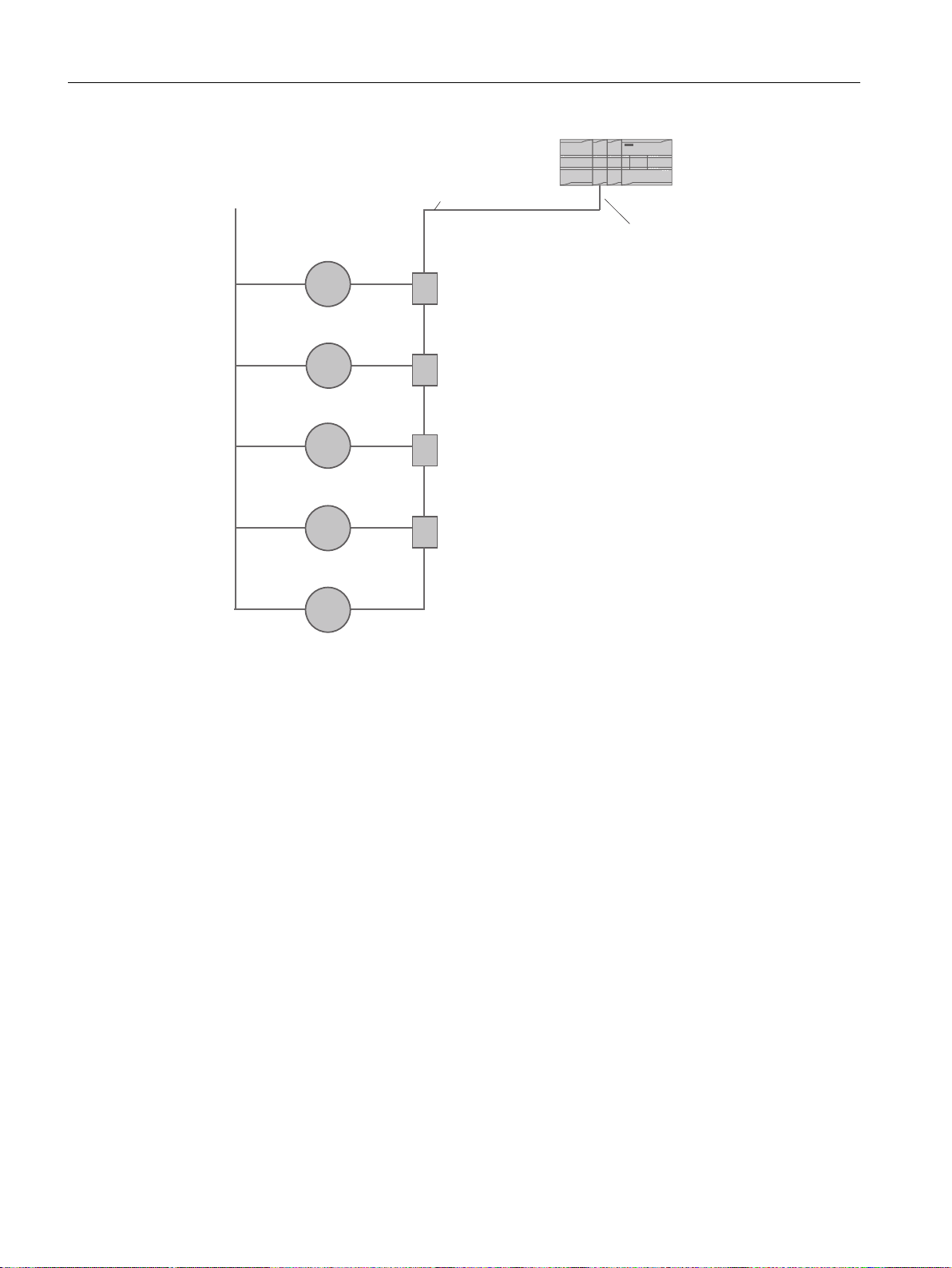
2.2 System configuration
Non-hazardous areas
The following figures show examples of installations in point-to-point and multidrop
configurations in non-hazardous areas.
2
Figure 2-1 Point to point configuration in non-hazardous locations
FCT030 Modbus (From firmware 4.0)
Function Manual, 06/2018, A5E39931813-AB 9
Page 10
&RQQHFWLRQ
ER[
0HDVXULQJ
GHYLFH
&RQQHFWLRQ
ER[
&RQQHFWLRQ
ER[
&RQQHFWLRQ
ER[
56
0DVWHU
ZLUH
FDEOH
3RZHU
VXSSO\
Communication
2.2 System configuration
Figure 2-2 Multidrop configuration (branch) in non-hazardous area
FCT030 Modbus (From firmware 4.0)
10 Function Manual, 06/2018, A5E39931813-AB
Page 11
56
0DVWHU
ZLUH
FDEOH
0HDVXULQJ
GHYLFH
3RZHU
VXSSO\
0DVWHU
56
+D]DUGRXV
ORFDWLRQ
1RQKD]DUGRXV
ORFDWLRQ
&RQGXLWVHDOV
0HDVXULQJ
GHYLFH
Communication
2.2 System configuration
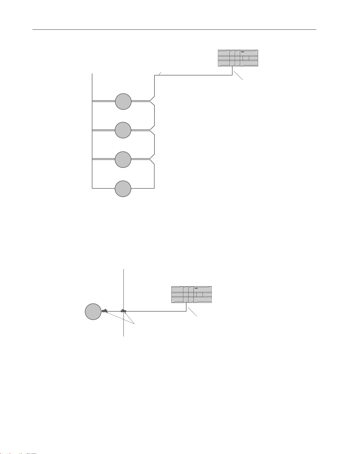
Hazardous areas
Figure 2-3 Multidrop configuration (Daisy chain) in non-hazardous area
The following figures show examples of installations in point-to-point and multidrop
configurations in hazardous areas.
Figure 2-4 Point-to-point configuration in hazardous area
FCT030 Modbus (From firmware 4.0)
Function Manual, 06/2018, A5E39931813-AB 11
Page 12
56
&RQQHFWLRQ
ER[
ZLUH
FDEOH
&RQQHFWLRQ
ER[
&RQQHFWLRQ
ER[
&RQGXLWVHDOV
3RZHU
VXSSO\
0HDVXULQJ
GHYLFH
3RZHU
VXSSO\
0DVWHU
+D]DUGRXV
DUHD
1RQKD]DUGRXV
DUHD
0HDVXULQJ
GHYLFH
Communication
2.3 System wiring
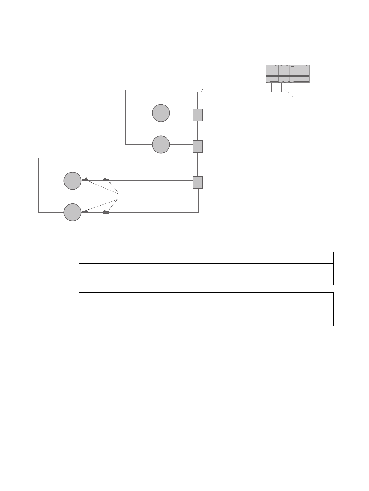
Figure 2-5 Multidrop configuration in hazardous area
NOTICE
Flameproof conduit seals
Two flameproof conduit seals are required for each device in hazardous area installations.
NOTICE
Equipment approved for hazardous areas
Ensure that the equipment is approved for installation in hazardous areas.
2.3 System wiring
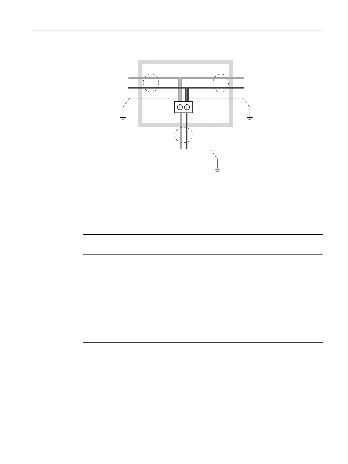
The device is slave in a 2-wire Modbus RTU RS 485 bus system. Terminal A on the device
must be connected to terminal A on the master/host system. Terminal B on the device must
be connected to terminal B on the master/host system. This corresponds to a half-duplex
communication where the slave will only reply to a request from the master.
This example shows an EMC shielded enclosure for multidrop installation. Cable shield must
be grounded at host system, in connection box, and at flowmeter to comply with EMC
requirements. Keep the cable shield to the ground as short as possible.
FCT030 Modbus (From firmware 4.0)
12 Function Manual, 06/2018, A5E39931813-AB
Page 13
A
B
A
B
B
A
&RQQHFWLRQ
IURPKRVW
V\VWHP
&RQQHFWLRQ
WRQH[W
GHYLFH
&RQQHFWLRQ
WRILUVWGHYLFH
&RQQHFWLRQER[
Communication
2.3 System wiring
Topology
The device supports a two-wire electrical interface in accordance with EIA/TIA-485 standard.
An RS485 Modbus configuration without repeater has one trunk cable, along which devices
are connected, directly (daisy chaining) or by short branch cables.
Note
Multidrop examples in this document show a trunk cable with short branch cables.
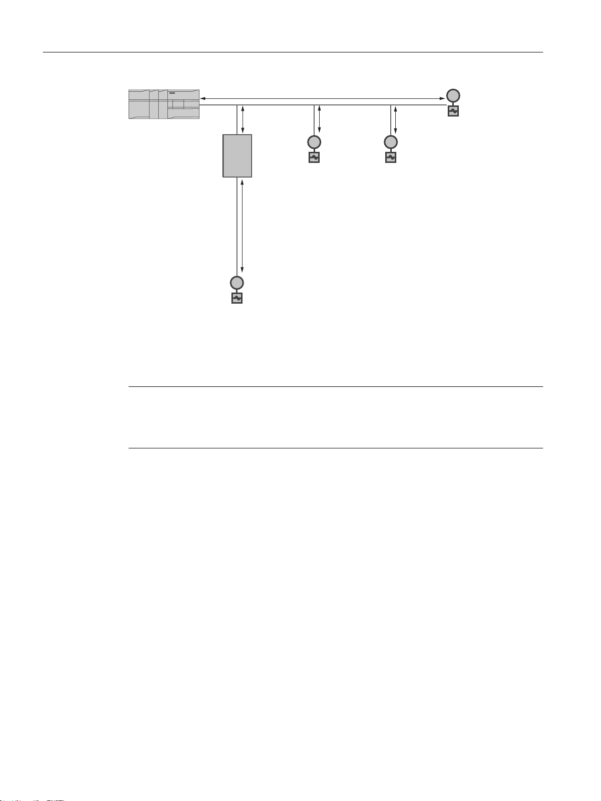
Maximum cable lengths
The end to end length of the trunk cable must be limited. The maximum length depends on
the baud rate, the cable (gauge, capacitance or characteristic impedance), the number and
types of loads on the daisy chain, and the network configuration.
Note
Maximum branch cable length
Branch cables must be short, never more than 20 m.
FCT030 Modbus (From firmware 4.0)
Function Manual, 06/2018, A5E39931813-AB 13
Page 14
P
P
P
P
P
+RVW
5HSHDWHU
Communication
2.4 Connecting
Figure 2-6 Maximum cable lengths in multidrop configuration
2.4 Connecting
Note
End Of Line (EOL) termination
The FCT030 EOL termination DIP switch is default set to EOL active. To change termination
setting see Setting the EOL termination DIP switches changed.
2.4.1 Connecting the Modbus (CH1)
1. Remove cap and ferrule from cable gland and slide onto cable.
2. Push cable through open gland and cable path.
3. Restore ferrule and tighten cap to lightly hold cable in place.
4. Signal cable screen is folded back over outer sheath and grounded beneath cable clamp.
FCT030 Modbus (From firmware 4.0)
14 Function Manual, 06/2018, A5E39931813-AB
Page 15
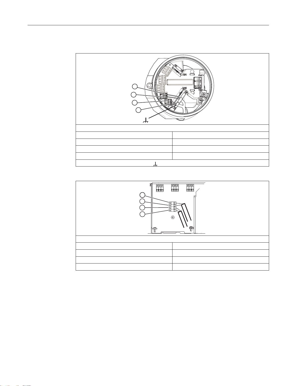
5. Connect wires to terminals using wiring tool, field mount transmitter
Modbus
④ In + (B)
⑤ In - (A)
⑥ Out + (B)
⑦ Out - (A)
Functional Earth
Communication
2.4 Connecting
6. Connect wires to terminals using wiring tool, wall mount transmitter.
Modbus
④ In + (B)
⑤ In - (A)
⑥ Out + (B)
⑦ Out - (A)
7. Tighten cable gland.
FCT030 Modbus (From firmware 4.0)
Function Manual, 06/2018, A5E39931813-AB 15
Page 16

Communication
2.4 Connecting
FCT030 Modbus (From firmware 4.0)
16 Function Manual, 06/2018, A5E39931813-AB
Page 17

Commissioning
3.1 General requirements
Before commissioning it must be checked that:
● The device has been installed and connected in accordance with the guidelines provided
in the Operating Instruction for FCT030 transmitter
3.2 Operating via SIMATIC PDM
SIMATIC PDM is a software package used to commission and maintain process devices.
3.3 Functions in SIMATIC PDM
SIMATIC PDM monitors the process values, alarms and status signals of the device. It allows
you to display, compare, adjust, verify, and simulate process device data; also to set schedules
for calibration and maintenance.
3
3.4 Commissioning steps
In the following it is described how to commission the device with SIMATIC PDM.
The steps are divided into the following sections:
1. Initial Setup (Page 17)
2. Adding a device to communication network (Page 20)
3. Wizard - Quick Start via PDM (Page 22)
4. Wizard - Zero Point adjustment (Page 29)
5. Configuring a new device (Page 21)
6. I/O configuration
7. Summary
3.5 Initial Setup
To ensure that SIMATIC PDM connects properly, please complete the two processes outlined
below:
FCT030 Modbus (From firmware 4.0)
Function Manual, 06/2018, A5E39931813-AB 17
Page 18
Commissioning
3.5 Initial Setup
1. Deactivating buffers
2. Updating the Electronic Device Description (EDD)
Deactivating buffers for RS 485 COM port
This deactivation is required to align SIMATIC PDM for Windows® operating systems.
Note
Support for Windows operating systems can be found here: support.automation.siemens.com
(http://support.automation.siemens.com)
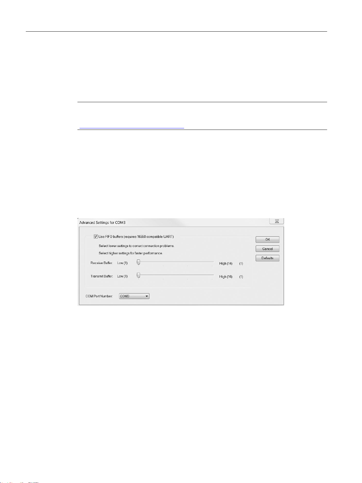
1. Click Start → Control Panel to begin configuration.
2. Click on Hardware and Sound and then on Device Manager.
3. Open Ports folder and double-click the COM Port used by the system to open the
Communications Port Properties window.
4. Select the Port Settings tab and click the Advanced button.
5. If the Use FIFO buffers check box is deselected, click to select.
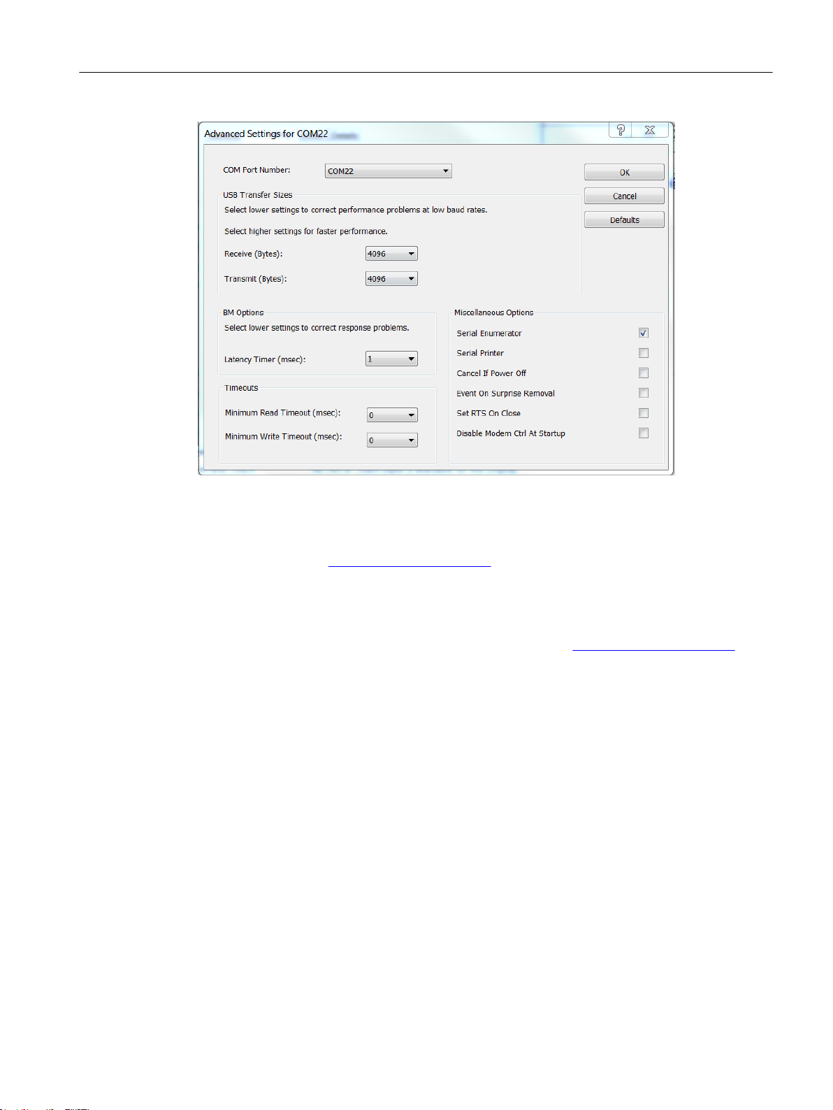
6. Set Receiver Buffer and Transmitter Buffer to Low (1).
Figure 3-1 COM Port Setting
For serial adapters it can be required to change the Latency Timer (msec) to 1.
FCT030 Modbus (From firmware 4.0)
18 Function Manual, 06/2018, A5E39931813-AB
Page 19
Commissioning
3.5 Initial Setup
See also
Updating the Electronic Device Description (EDD)
You can locate the EDD in the SIMATIC PDM Device Library under Devices → Modbus →
Sensors → Flow → Coriolis → Siemens AG → SITRANS FC430 and FC330. Check the product
page of our website (www.siemens.com/FC430) under Support > Software downloads, to
make sure you have the latest version of SIMATIC PDM, the most recent Service Pack (SP)
and the most recent hot fix (HF).
Installing a new EDD:
1. Download the EDD from the product page of our website (www.siemens.com/FC430) and
save the files to your computer.
2. Extract the zipped file to an easily accessed location.
3. Launch the SIMATIC PDM Device Integration Manager, browse to the unzipped EDD file
and select it.
Commissioning steps (Page 17)
Wizard - Quick Start via PDM (Page 22)
FCT030 Modbus (From firmware 4.0)
Function Manual, 06/2018, A5E39931813-AB 19
Page 20
Commissioning
3.6 Adding a device to communication network
3.6 Adding a device to communication network
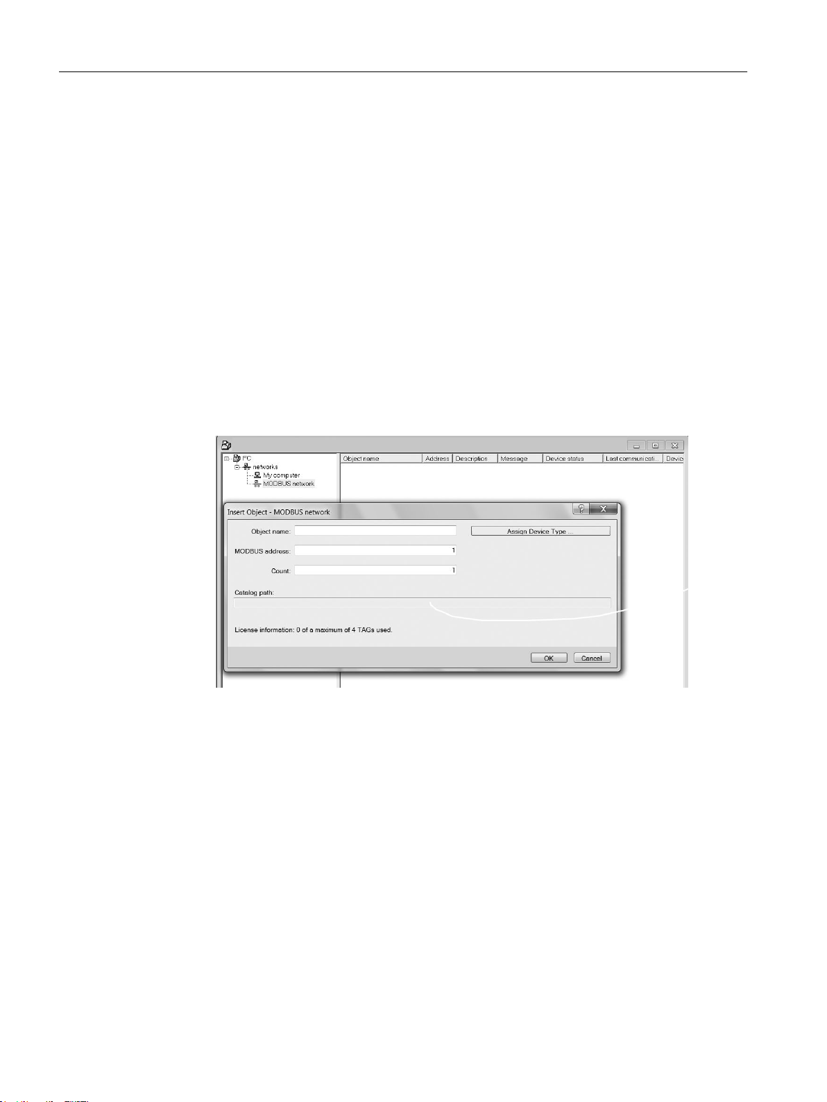
Before setting the parameters, it is necessary to configure the transmitter project in PDM.
1. Add the device to SIMATIC Modbus network:
– Select File → New
Type in a project name, for example
– Go to View and select Process Device Network view.
FC commissioning
.
– Right-click on the typed in
– Right-click on Networks and Insert New Object → Communication Network.
– Click on Assign Device Type and select Modbus Network.
Click OK two times. Your PC is now added to the Modbus Network.
– Right-click Modbus Network and select Insert New Object → Object.
– Click on Assign Device Type, and select Devices → Modbus → Sensors → Flow → Coriolis
→ SIEMENS AG → SITRANS FC
Click OK two times.
Project name
and select Insert New Object → Networks.
Figure 3-2 Assigning Modbus device to network
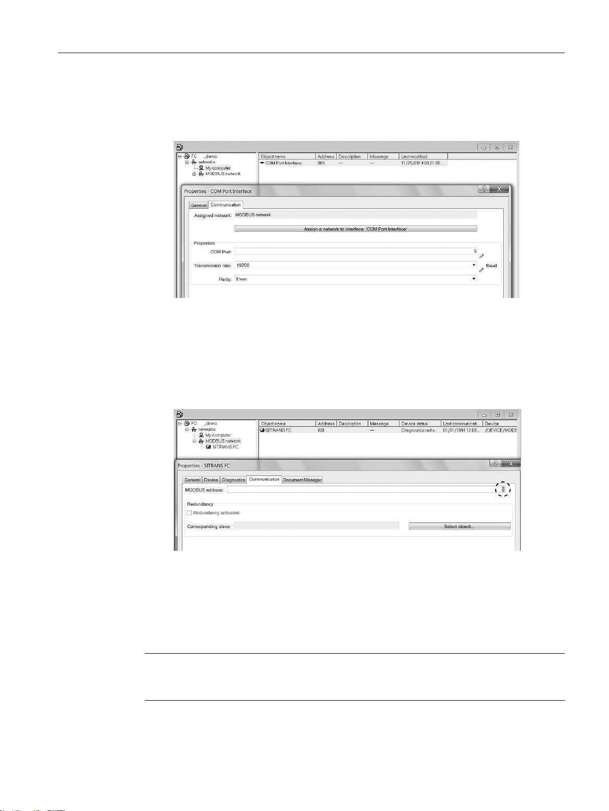
2. Set up the communication parameters for SIMATIC Modbus network:
– Select Networks → My computer, right-click on COM Port Interface and select Object
Properties.
FCT030 Modbus (From firmware 4.0)
20 Function Manual, 06/2018, A5E39931813-AB
Page 21
Commissioning
3.7 Configuring a new device
– Select the Communication tab and configure the communication parameters. The
transmitters default settings are:
- Transmission rate: 19200 baud
- Parity: even
Figure 3-3 Modbus net object properties
– Click OK.
3. Set up the COM interface:
– Select Modbus Networks.
– Right-click on the object name SITRANS FC and select Object Properties.
– Select the Communication tab and configure the Modbus address.
Figure 3-4 Set the Modbus address
– Click OK.
3.7 Configuring a new device
Note
Clicking on Cancel during an upload from device to SIMATIC PDM will result in some
parameters NOT being updated.
FCT030 Modbus (From firmware 4.0)
Function Manual, 06/2018, A5E39931813-AB 21
Page 22

Commissioning
3.8 Wizard - Quick Start via PDM
1. Check that you have the most recent EDD, and if necessary update it, see Updating the
Electronic Device Description (EDD) in Initial Setup (Page 17).
2. Launch SIMATIC Manager.
3. Right-click on SITRANS FC and select Open Object to open SIMATIC PDM.
4. Click on Device and select Upload to PG/PC Wizard... to configure the device.
3.8 Wizard - Quick Start via PDM
The graphic Quick Start Wizard provides an easy 5-step procedure that configures the device
for a simple application.
Please consult the SIMATIC PDM operating instructions or online help for details on using
SIMATIC PDM.
Access level control
The parameters are protected against changes by access level control. To gain access, select
Access Management from the device menu, select User and enter the PIN code.
Quick start
The default user PIN code is 2457.
Note
- The Quick Start wizard settings are inter-related and changes apply only after you click on
Apply and Transfer at the end of step 5 to save settings offline and transfer them to the device.
- Do not use the Quick Start Wizard to modify individual parameters.
- Click on Back to return and revise settings or Cancel to exit the Quick Start.
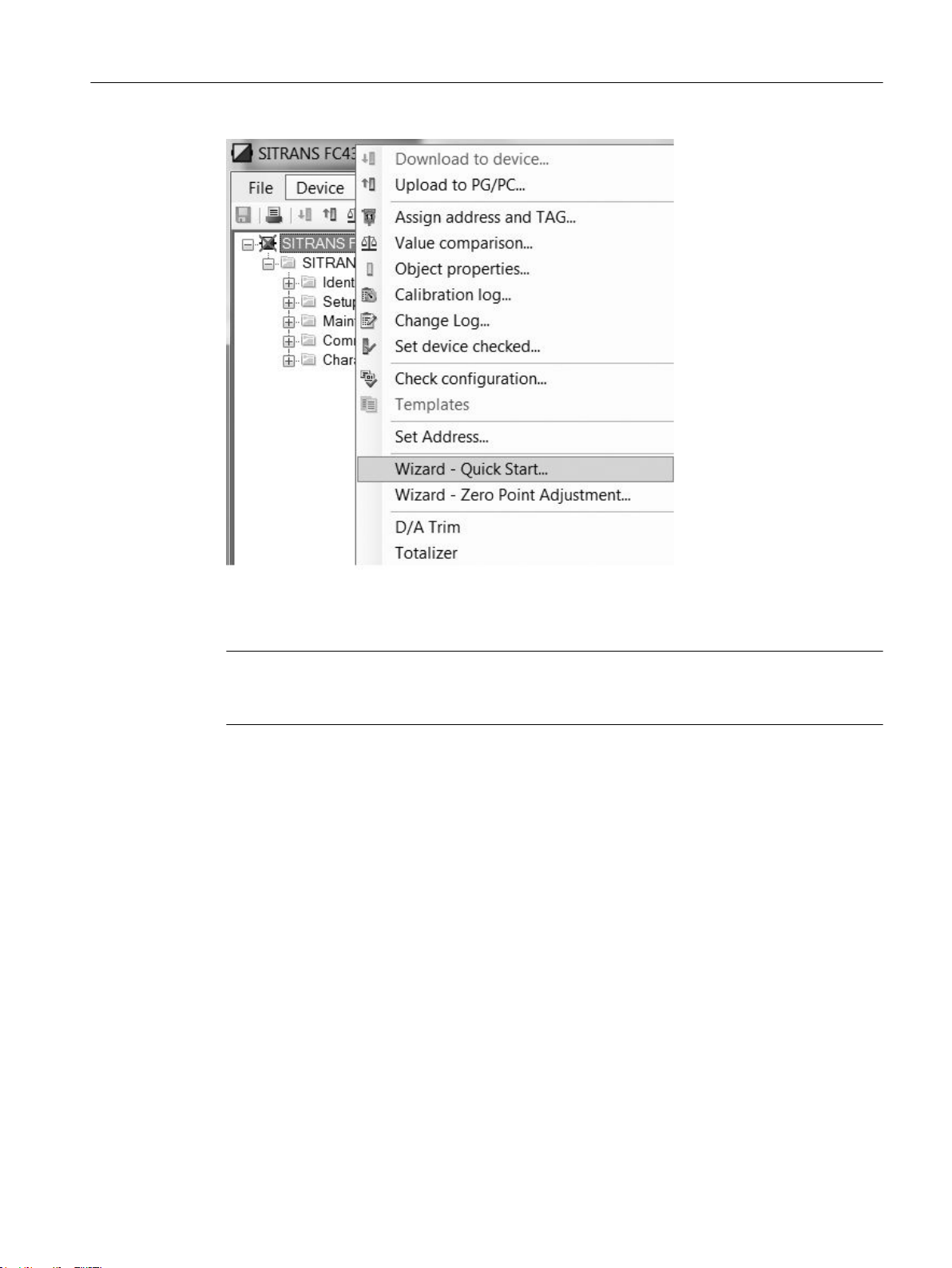
Launch SIMATIC PDM, open the menu Device → Wizard - Quick Start..., and follow steps 1
to 5.
FCT030 Modbus (From firmware 4.0)
22 Function Manual, 06/2018, A5E39931813-AB
Page 23
Commissioning
3.8 Wizard - Quick Start via PDM
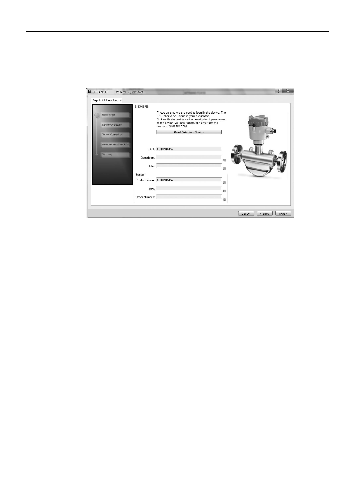
Step 1 - Identification
Note
The layout of the dialog boxes shown may vary according to the resolution setting for your
computer monitor. The recommended resolution is 1280 x 960.
FCT030 Modbus (From firmware 4.0)
Function Manual, 06/2018, A5E39931813-AB 23
Page 24
Commissioning
3.8 Wizard - Quick Start via PDM
1. Click on Read Data from Device to upload Quick Start parameter settings from the device
to the PC/PG and ensure PDM is synchronized with the device.
2. Click on Next to accept the default values. (Descriptor, Message, and Date fields can be
left blank.)
Figure 3-5 Quick start step 1
FCT030 Modbus (From firmware 4.0)
24 Function Manual, 06/2018, A5E39931813-AB
Page 25
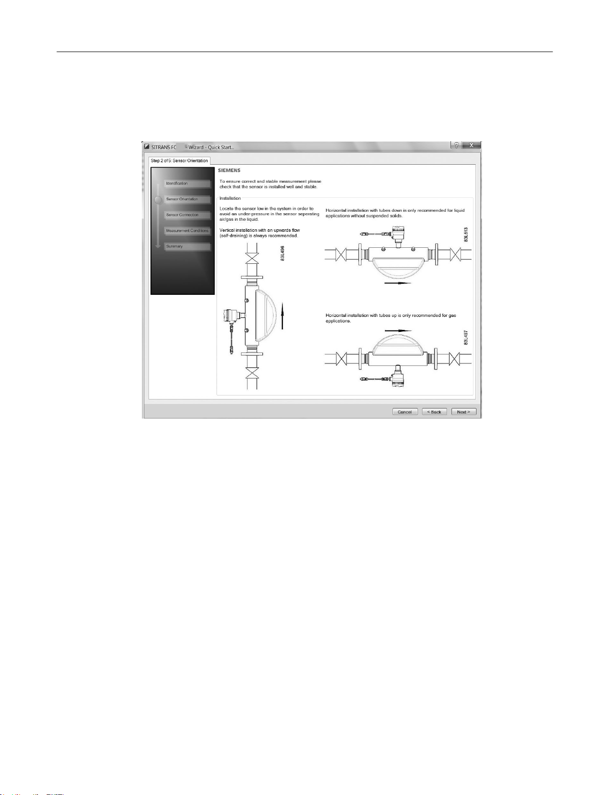
Step 2 - Sensor orientation
Step 2 shows an overview of the various recommended installation orientations depending on
the application.
Commissioning
3.8 Wizard - Quick Start via PDM
Figure 3-6 Quick start step 2
FCT030 Modbus (From firmware 4.0)
Function Manual, 06/2018, A5E39931813-AB 25
Page 26
Commissioning
3.8 Wizard - Quick Start via PDM
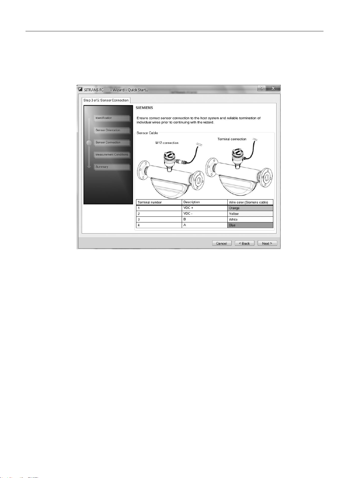
Step 3 - Sensor connection
The transmitter can be ordered with M12 connection or with terminated cable (for example
conduit connections).
Figure 3-7 Quick start step 3
FCT030 Modbus (From firmware 4.0)
26 Function Manual, 06/2018, A5E39931813-AB
Page 27
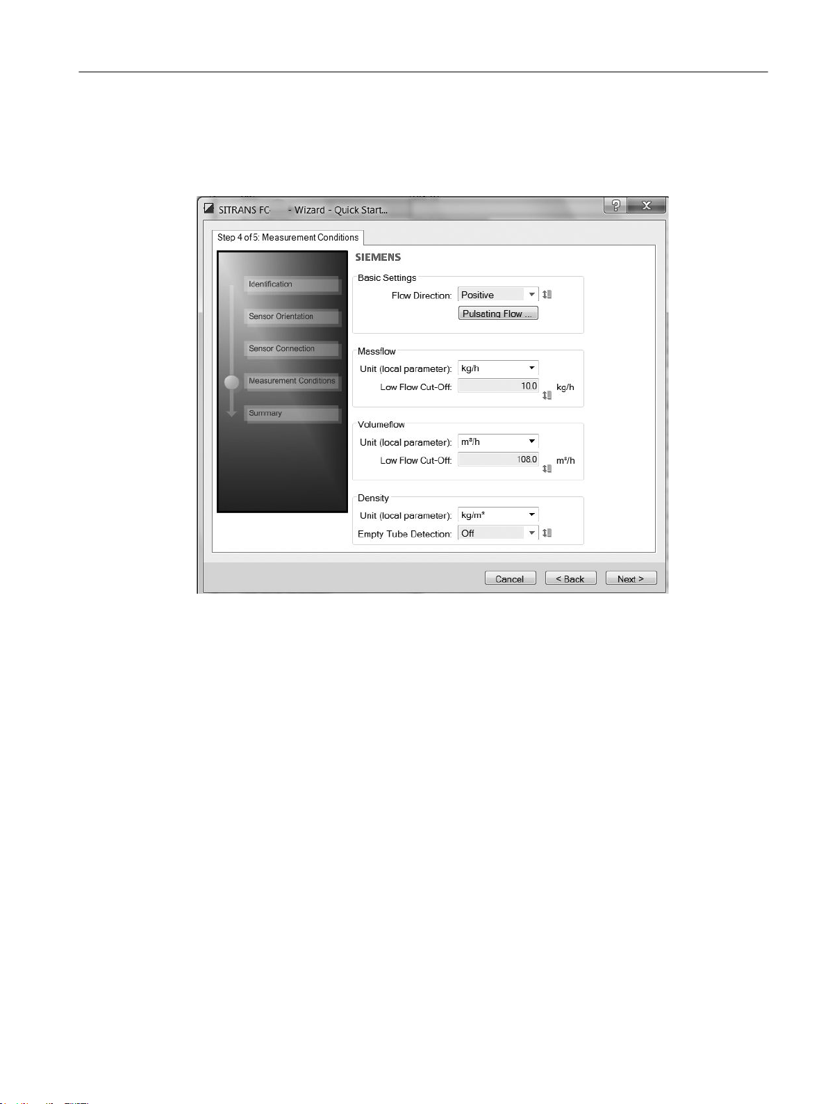
Step 4 - Measurement conditions
Configure the measurement conditions for the selected process variables. Change Flow
Direction if necessary.
Commissioning
3.8 Wizard - Quick Start via PDM
Figure 3-8 Quick start step 4
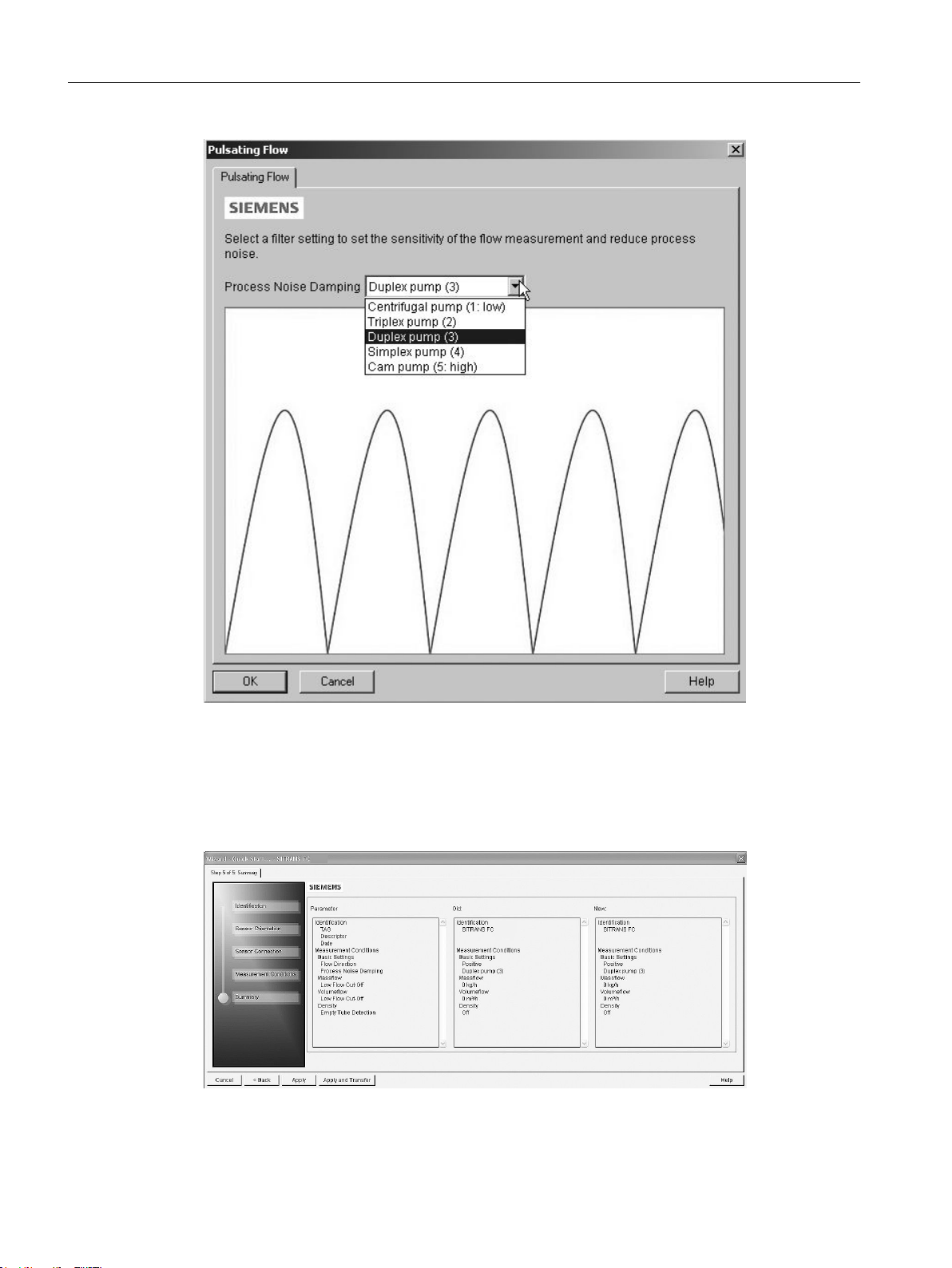
Reduce the sensitivity of the flow measurement signal by clicking on the Pulsating Flow button
and selecting the appropriate filter.
FCT030 Modbus (From firmware 4.0)
Function Manual, 06/2018, A5E39931813-AB 27
Page 28
Commissioning
3.8 Wizard - Quick Start via PDM
Step 5 - Summary
Figure 3-9 Filter setting selection
Check parameter settings, and click on Back to return and revise values, Apply to save settings
offline, or Apply and Transfer to save settings offline and transfer them to the device.
Figure 3-10 Quick start step 5
The message Quick Start was successful will appear. Click on OK.
FCT030 Modbus (From firmware 4.0)
28 Function Manual, 06/2018, A5E39931813-AB
Page 29
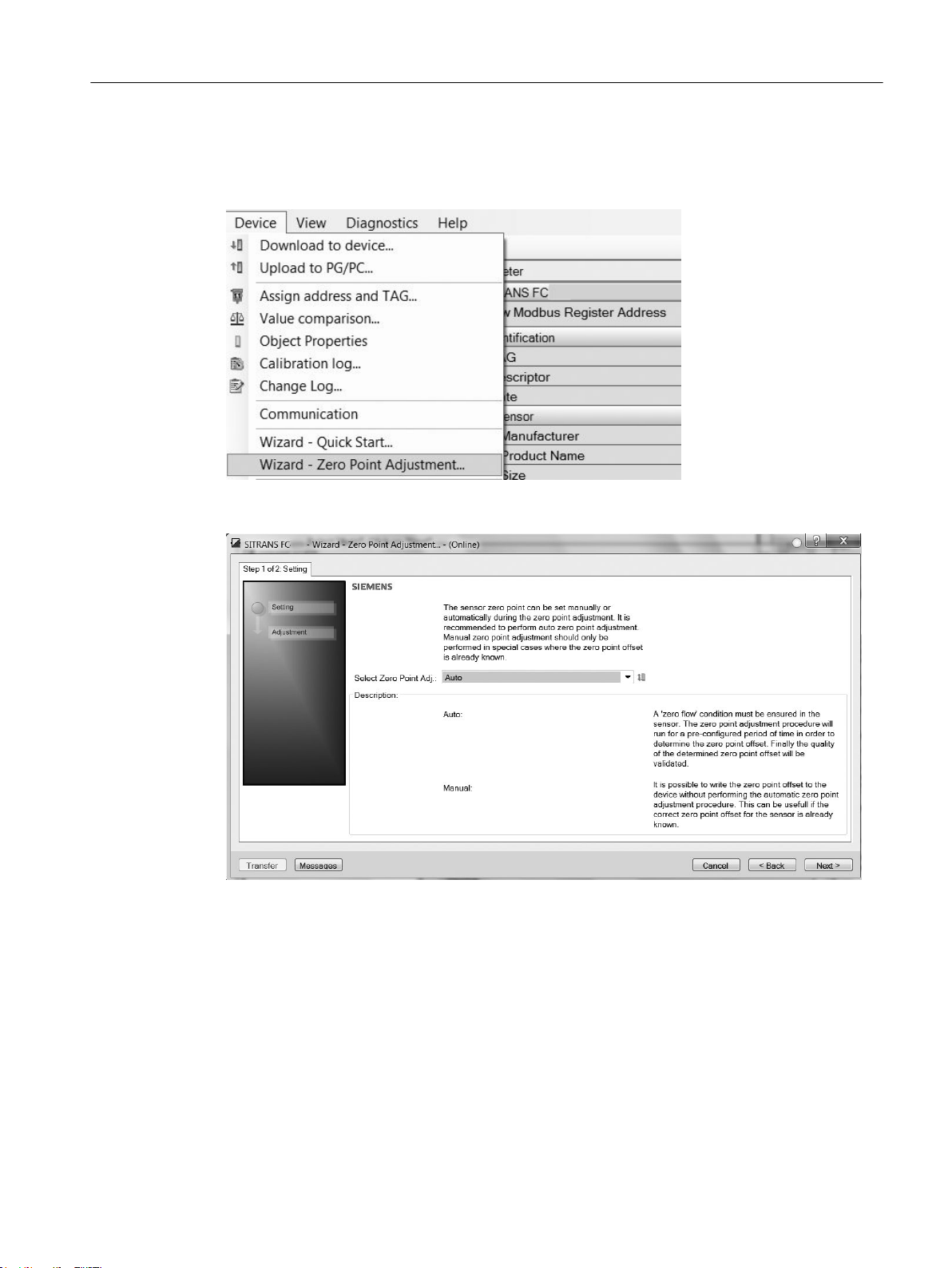
3.9 Wizard - Zero Point adjustment
Open the menu Device → Wizard → Zero Point Adjustment.
Select Auto. Click on Next.
Commissioning
3.9 Wizard - Zero Point adjustment
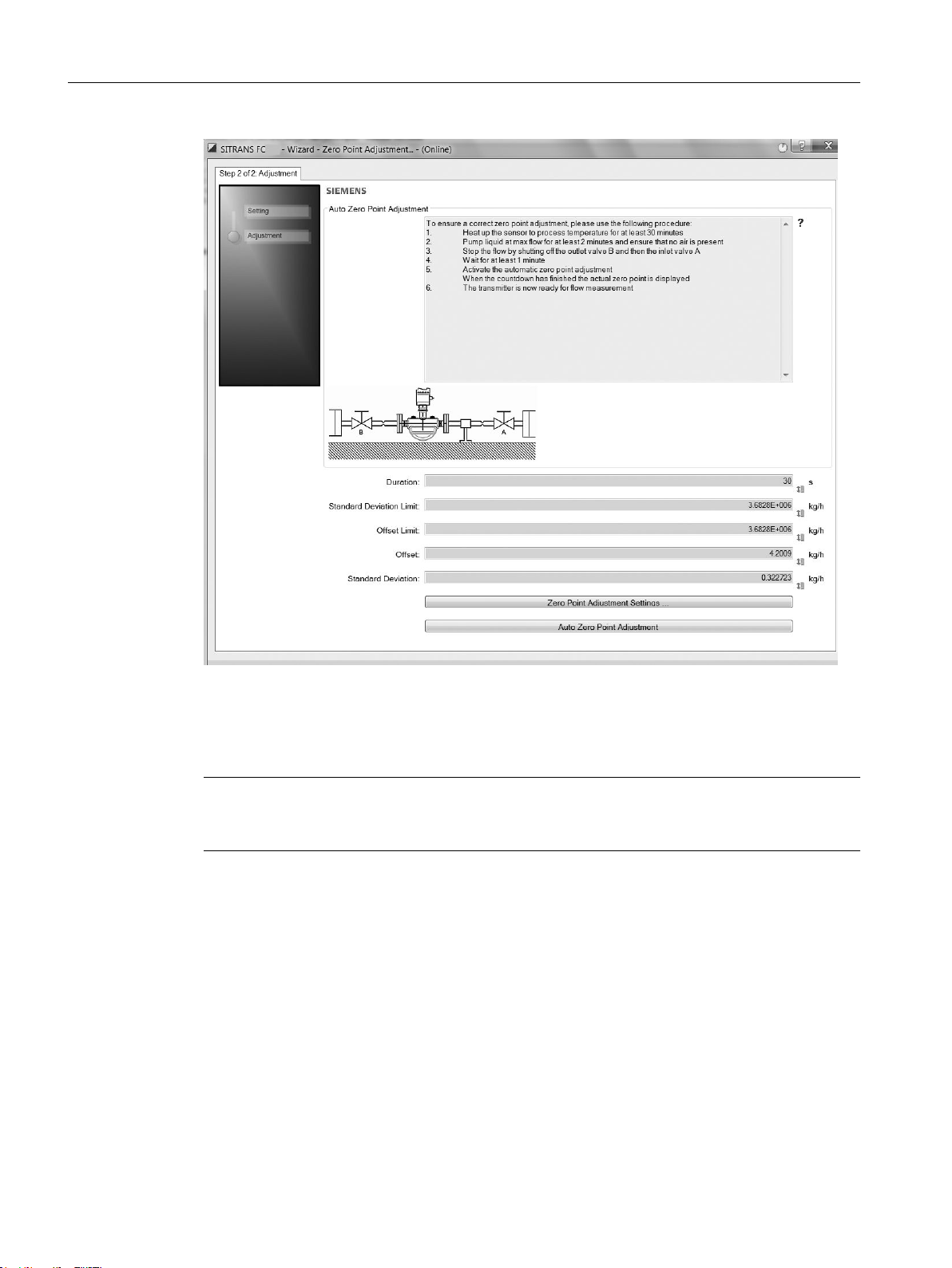
It is recommended to use the default settings. Change the Zero Point Adjustments Settings,
if necessary.
Click on Auto Zero Point Adjustment.
FCT030 Modbus (From firmware 4.0)
Function Manual, 06/2018, A5E39931813-AB 29
Page 30
Commissioning
3.10 Changing parameter settings using SIMATIC PDM
3.10 Changing parameter settings using SIMATIC PDM
Note
Clicking on Cancel during an upload from device to SIMATIC PDM will result in some
parameters NOT being updated.
FCT030 Modbus (From firmware 4.0)
30 Function Manual, 06/2018, A5E39931813-AB
Page 31
Commissioning
3.11 Parameters accessed via drop-down menus
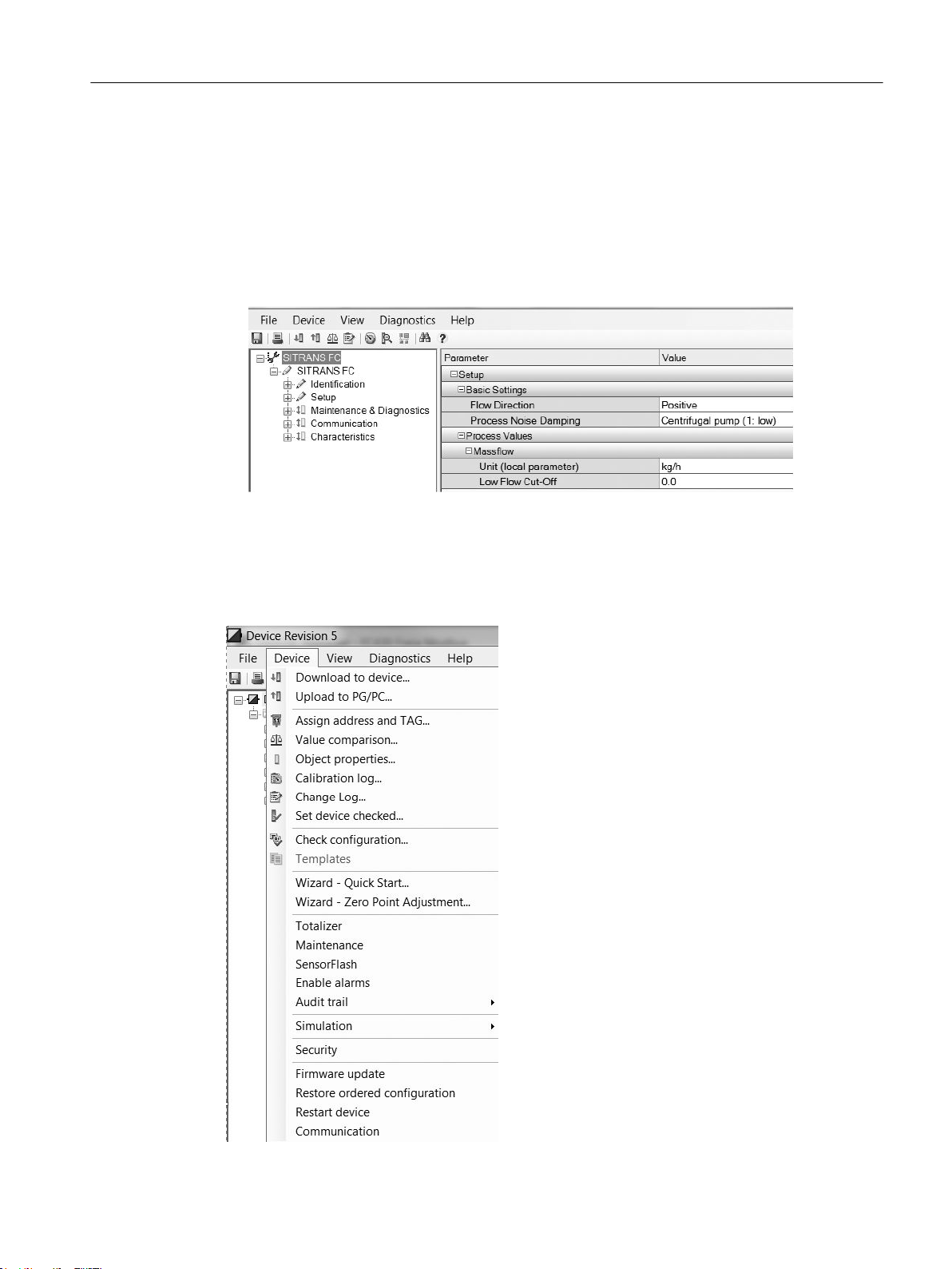
Many parameters are accessed via the online menus in SIMATIC PDM, see Parameters
accessed via drop-down menus for the others.
1. Launch SIMATIC PDM, connect to the appropriate device and upload data.
2. Adjust parameter values in the parameter value field then click on Enter. The status fields
read Changed.
3. Open the Device menu, click on Download to device, then use File → Save to save settings
offline. The status fields are cleared.
3.11 Parameters accessed via drop-down menus
Click on Device or View to open the associated drop-down menus.
FCT030 Modbus (From firmware 4.0)
Function Manual, 06/2018, A5E39931813-AB 31
Page 32

Commissioning
3.11 Parameters accessed via drop-down menus
Drop-down menus
Table 3-1 Device menus
Device menus Description
Download to Device Downloads all writable parameters to the device
Upload to PC/PG Uploads all parameters from the device to the parameter
Assign address and TAG Assign communication address and TAG name
Value comparison Compare values between device / project
Object properties Properties for device and project
Calibration log Create calibration logs for field devices.
Change log The change log records which actions have been per‐
Set the device checked The device can be set to checked / or unchecked
Check configuration Check configuration if it contains errors
Wizard - Quick Start Guide for a quick commissioning
Wizard - Zero Point Adjustment Guide for zero point adjustment (automatic and manual)
table
formed with SIMATIC PDM on devices
Table 3-2 View menus
View menus Description
Process Variables (online dialog) Shows all process values
Device Diagnostic (online dialog) Shows all diagnostics information (alarms and diagnostics
parameters)
Toolbar (online dialog) Shows/hides the toolbar
Status Bar Shows/hides the status bar
Update Updates the content of the active window
FCT030 Modbus (From firmware 4.0)
32 Function Manual, 06/2018, A5E39931813-AB
Page 33

MODBUS commands
4.1 Modbus addressing model
The device allows read/write access to one holding register block. All devices are mapped to
this Modbus address space.
4.2 Modbus communication
Table 4-1 General Modbus settings
4
Modbus
register
8291 Unsigned / 2Restart com‐
8005 Unsigned / 2Slave address
8297 Unsigned / 2Slave address
Data type /
Size in
bytes
Parameter Description Default val‐
munication
(HW)
(SW)
Restarts the communication using
configured slave address, baud rate
and parity/framing.
DIP switch setting on the transmitter
cassette. Address is used if DIP
switch is set to a value > 0.
Software address of Modbus inter‐
face. Address is used if switch is set
to 0.
Value range /
ue
[units]
(units
register)
-
- - Read only
1 1 - 147 Read /
Setting options
● 0: Cancel
● 1: Restart
Access
level
Write only
write
FCT030 Modbus (From firmware 4.0)
Function Manual, 06/2018, A5E39931813-AB 33
Page 34

MODBUS commands
4.2 Modbus communication
Modbus
register
8298 Unsigned / 2Baud rate Baud rate of Modbus interface. 19200 Bit/s
8299 Unsigned / 2Parity and
Data type /
Size in
bytes
Parameter Description Default val‐
ue
[units]
(units
register)
framing
Parity and framing of the Modbus
communication interface.
Even pari‐
ty, 1 stop
Value range /
Setting options
● 0: 9600 Bit/s
● 1: 19200 Bit/
s
● 2: 115200
Bit/s
● 3: Reserved
● 4: 38400 Bit/
s
● 5: 57600 Bit/
s
● 6: 76800 Bit/
s
● 7: 1200 Bit/s
● 8: 2400 Bit/s
● 9: 4800 Bit/s
● 0: Even
parity, 1 stop
● 1: Odd
parity, 1 stop
● 2: No parity,
2 stops
Access
level
Read /
write
Read /
write
FCT030 Modbus (From firmware 4.0)
34 Function Manual, 06/2018, A5E39931813-AB
Page 35

4.3 Coil configuration
The device provides 20 coil definitions which can be configured.
Table 4-2 Coil configuration
MODBUS commands
4.3 Coil configuration
Modbus
register
10300 Unsigned / 2 Modbus coil ad‐
10301 Unsigned / 2 Modbus coil
10302 Unsigned / 4 Modbus coil bit‐
10304 Unsigned / 2 Modbus coil
10305 Unsigned / 2 Modbus coil ad‐
10306 Unsigned / 2 Modbus coil
Data type /
Size in bytes
Parameter Description Default value
dress 1
register 1
mask 1
length 1
dress 2
register 2
Specifies the coil address with
which the following bit coded
register value is accessible.
The register and bit(s) are
specified by Modbus coil reg‐
ister 1and Modbus coil bit‐
mask 1
Specifies the Modbus register
whose value is checked
against Modbus coil bitmask 1
to determine the coil value
(false or true). A register value
of 65535 specifies that this coil
mapping is undefined.
Bit mask which is compared
against the register value
specified with Modbus coil reg‐
ister 1 to determine the coil
value. If any bit of the register
value is set which is also set
in the bit mask then the coil
value is true, otherwise the
coil is false.
Output parameter that informs
about the size in bytes of the
parameter that is specified by
Modbus coil address 1. Could
be used to identify the relevant
bits of the Modbus coil bit‐
mask 1
Specifies the coil address with
which the following bit coded
register value is accessible.
The register and bit(s) are
specified by Modbus coil reg‐
ister 2 and Modbus coil bit‐
mask 2
Specifies the Modbus register
whose value is checked
against Modbus coil bitmask 2
to determine the coil value
(false or true). A register value
of 65535 specifies that this coil
mapping is undefined.
1
[units]
(units register)
1 0 - 65535 Read / write
Undefined 0 - 65535 Read / write
0 0 - 4294967295 Read / write
- Read only
2 0 - 65535 Read / write
Undefined Read / write
Value range /
Setting options
Access lev‐
el
FCT030 Modbus (From firmware 4.0)
Function Manual, 06/2018, A5E39931813-AB 35
Page 36

MODBUS commands
4.4 Modbus register mapping
Modbus
register
10307 Unsigned / 4 Modbus coil bit‐
10309 Unsigned / 2 Modbus coil
...
10399 Unsigned / 2 Modbus coil
Data type /
Size in bytes
1
If default value is "-" the command "Set to default" will not set this parameter to default.
Parameter Description Default value
mask 2
length 2
length 20
Bit mask which is compared
against the register value
specified with Modbus coil reg‐
ister 2 to determine the coil
value. If any bit of the register
value is set which is also set
in the bit mask then the coil
value is true otherwise false.
Output parameter that informs
about size in bytes of parame‐
ter that is specified by Modbus
coil address 2. Could be used
to identify the relevant bits of
the Modbus coil bitmask 2
Output parameter that informs
about the size in bytes of the
parameter that is specified by
Modbus coil address 20.
Could be used to identify the
relevant bits of the Modbus
coil bitmask 20
1
[units]
(units register)
0 0 - 4294967295 Read / write
- Read only
- Read only
Value range /
Setting options
Access lev‐
el
4.4 Modbus register mapping
The device provides the possibility to map each existing parameter to a freely chosen Modbus
register for communication purposes over channel 1.
FCT030 Modbus (From firmware 4.0)
36 Function Manual, 06/2018, A5E39931813-AB
Page 37

The device provides means to remap 20 Modbus registers.
Table 4-3 Modbus register mapping
MODBUS commands
4.4 Modbus register mapping
Modbus
register
10448 Unsigned / 4Enable mapping Activation/deactivation of
10450 Unsigned / 2Register 1 source Modbus register that ap‐
10451 Unsigned / 2Register 1 target Register of an existing prod‐
...
10488 Unsigned / 2Register 20 source Modbus register that ap‐
10489 Unsigned / 2Register 20 target Register of an existing prod‐
Data type /
Size in
bytes
Parameter Description Default value
the register mapping. A set
bit means that the mapping
pair is activated, a cleared bit
that the mapping pair is de‐
activated.
Bit 0:
Requested register 1 / Tar‐
get register 1
…
Bit 19:
Requested register 20 / Tar‐
get register 20
pears within Modbus re‐
quest is redirected to the pa‐
rameter specified by Target
register 1
uct parameter to which a
Modbus request is redirected
pears within Modbus re‐
quest is redirected to the pa‐
rameter specified by Target
register 20
uct parameter to which a
Modbus request is redirected
Value range /
[units]
(units register)
0 0 - 1048575 Read /
65535 0 - 65535 Read /
65535 0 - 65535 Read /
65535 0 - 65535 Read /
65535 0 - 65535 Read /
Setting op‐
tions
Access
level
write
write
write
write
write
FCT030 Modbus (From firmware 4.0)
Function Manual, 06/2018, A5E39931813-AB 37
Page 38

MODBUS commands
4.6 Float transmission
4.5 Integer byte order
The device is able to adjust the byte order of integer values.
Table 4-4 Integer byte order
Modbus
register
8295 Unsigned / 2Integer order byte The integer byte order used
Data type /
Size in
bytes
Parameter Description Default value
in Modbus messages.
0: MSB - LSB (big endian)
1: LSB - MSB (little endian)
MSB = most significant byte /
high byte
LSB = least significant byte /
low byte
4.6 Float transmission
The Float Byte Order function ensures that the master and slave use the same sequence of
the bytes when transmitting float values. This enables the user to configure the FCT030 and
operate the device with all types of PLCs without reprogramming the PLC. The transmission
order is configured by setting the parameter Byte Order in the submenu Device →
Communication.
Note
The command Restart Communication must be executed to activate the new byte order setting.
[units]
(units register)
MSB - LSB
(big endian)
Value range /
Setting op‐
tions
0 - 1 Read /
Access
level
write
The table in chapter Float byte order (Page 39) shows the different options for setting the
transmission method.
FCT030 Modbus (From firmware 4.0)
38 Function Manual, 06/2018, A5E39931813-AB
Page 39

4.7 Float byte order
The device is able to adjust the byte order of floating-point values.
Table 4-5 Float byte order
MODBUS commands
4.8 Modbus function codes
Modbus
register
8296 Unsigned / 2Float byte order The float byte order used in
Data type /
Size in
bytes
Parameter Description Default value
[units]
(units register)
3-2-1-0 0 - 3 Read /
Modbus messages.
0: 1-0-3-2
1: 0-1-2-3
2: 2-3-0-1
3: 3-2-1-0
The first mentioned byte is
the first byte sent.
Byte 3 corresponds to the
left-most byte (MSB) of a 32
bit floating point number in
big endian format, byte 0 to
the right-most byte
Value range /
Setting op‐
tions
Access
level
write
4.8 Modbus function codes
Table 4-6 General Modbus settings
Function code Command text Description
01 Read Coils Reads the status of single bit(s)
02 Read Discrete Inputs Reads the status of single input bit(s)
03 Read Holding Registers Reads the binary content of multiple 16-bit registers
04 Read Input Registers Reads the binary content of multiple 16-bit registers
05 Write Single Coil Writes a single on/off bit
06 Write Single Register Writes the binary content of single 16-bit register
07 Read Exception Status Delivers the global alarm status of the device
08 Diagnostics Provides a series of tests for checking the communication sys‐
tem
15 Write Multiple Coils Writes multiple on/off bits
16 Write Multiple Registers Writes the binary content of multiple 16-bit registers
17 Report Slave ID The device will respond to a Report Slave ID command (com‐
mand 17) request from the master by giving information about
device type, vendor, and revision level
23 Read/Write Multiple Registers Combined Write Multiple Registers / Read Holding Registers call
Function code 7 (Read exception status)
The device provides the content of the parameter Global alarm status as exceptions.
FCT030 Modbus (From firmware 4.0)
Function Manual, 06/2018, A5E39931813-AB 39
Page 40

MODBUS commands
4.9 Access control
Function code 8 (Diagnostics)
The diagnostics function provides means for checking the communication between MODBUS
master and slave. The function uses a sub-function code to select the functionality.
The following sub-function codes are supported:
Sub-function code Name Description
0 Return query data The data passed in the request data field will be returned (loo‐
ped back) in the response. The entire response message should
be identical to the request.
1 Restart communications option After having restarted the communication, select the baudrate,
framing or Modbus address to get access to the device again.
Function code 17 (Report Slave ID)
The transmitter will respond to a Report Slave ID request from the master by giving information
about device type, vendor, and firmware version in a format as shown:
Response
Slave address 1 byte
Function code 1 byte 17
Byte count 1 byte 62
Slave ID 1 byte Sensor device type
0: SITRANS FC
Run indicator 1 byte 255: Running
Manufacturer name 12 bytes SIEMENS
Product name 32 bytes SITRANS F
Product firmware
version
CRC 2 bytes
16 bytes -
4.9 Access control
Access control manages whether the Modbus master is allowed to modify device parameters.
Reading of parameters is always possible. The general access control rules are:
● The Modbus interface has an access level that can be changed by providing PIN information
via the Modbus register 8292 (User PIN) or 8293 (Expert PIN).
● Each parameter has a protection level assigned that specifies the required access level to
modify the parameter via the Modbus interface.
● If the access level of the Modbus interface is lower than the protection level of the parameter
that is desired to be modified, then the attempt to modify the parameter is rejected by the
device.
FCT030 Modbus (From firmware 4.0)
40 Function Manual, 06/2018, A5E39931813-AB
Page 41

MODBUS commands
4.10 Modbus holding registers tables
If the device is defined as a custody transfer (CT) device and the CT write protection DIP switch
is ON (locked), the device will deny all writes to CT parameters independent of the access
control.
Table 4-7 Access control
Access level Description
Read only The Modbus master is not able to modify the device configuration (setup parameters).
The Modbus master is only able to execute the command, to reset PINs.
This is the default level of the Modbus interface.
User The Modbus master has to provide the correct user PIN with Modbus register 8292 to reach this access
level.
The Modbus master is able to modify a subset of the device configuration.
Expert The Modbus master has to provide the correct expert PIN with Modbus register 8293 to reach this
access level. The Modbus master is able to modify the configuration of the device.
If an incorrect user PIN or an incorrect expert PIN is entered, or if the device does not receive
any request within 10 minutes, the device resets the access level to read only.
4.10 Modbus holding registers tables
4.10.1 Modbus holding registers tables (intro)
In the following the Modbus RTU holding registers available for SITRANS FST030 are
described.
Note
All Write parameters require password access.
Note
In case of error message "Check if the device is set to CT or SIL Operation mode", please
check for the following root causes:
- The device is set to CT mode
- The device is set to SIL mode
- The used Modbus register address is wrong
FCT030 Modbus (From firmware 4.0)
Function Manual, 06/2018, A5E39931813-AB 41
Page 42

MODBUS commands
4.10 Modbus holding registers tables
4.10.2 Process values
Table 4-8 Process values for standard FC applications
Modbus
register
3000 Float / 4 Mass flow Measured mass flow [kg/s]
3002 Float / 4 Volume flow Measured volume flow [m³/s]
3004 Float / 4 Density Measured density [kg/s]
3010 Float / 4 Medium temper‐
3023 Float / 4 Frame temper‐
7950 Float / 4 Standard volu‐
7871 Float / 4 Fraction A Fractional flow of medi‐
7881 Float / 4 Fraction B Fractional flow of medi‐
7800 Float / 4 Fraction A % Fraction Flow Media A
7810 Float / 4 Fraction B % Fraction Flow Media B
Data type /
Size in bytes
Parameter Description Default value
[units]
(units register)
(7400)
(7500)
(7600)
ature
ture
meflow
Measured medium tem‐
perature
Measured frame tem‐
perature
Calculated volume flow [°C]
um A
um B
in Percent
in Percent
[°C]
(7700)
[°C]
(7700)
(7964)
[Kg/h]
(7865) mass‐
flow
[m3/h]
(7867) volu‐
meflow
[Kg/h]
(7865) mass‐
flow
[m3/h]
(7867) volu‐
meflow
- Read
- Read
Value range /
Setting options
- Read
- Read
- Read
- Read
- Read
- Read
- Read
Read
Access
level
only
only
only
only
only
only
only
only
only
only
Table 4-9 IO values
Modbus
register
8803 Float / 4 Loop current
8900 Float / 4 Output frequen‐
Data type /
Size in bytes
Parameter Description Default value
[units]
(units register)
CH2
cy CH2
Calculated current at
output channel 2
Calculated frequency
at output channel 2
[mA]
[Hz]
Value range /
Setting options
Read
Read
FCT030 Modbus (From firmware 4.0)
Access
level
only
only
42 Function Manual, 06/2018, A5E39931813-AB
Page 43

MODBUS commands
4.10 Modbus holding registers tables
Modbus
register
8969 Float / 4 Amount on CH2 Current totalized
8840 Unsigned / 2 Status output
9103 Float / 4 Loop current
9200 Float / 4 Output frequen‐
9269 Float / 4 Amount on CH3 Current totalized
9140 Unsigned / 2 Status output
10503 Float / 4 Input current
9129 Unsigned / 2 Digital input sig‐
9303 Float / 4 Loop current
9400 Float / 4 Output frequen‐
9469 Float / 4 Amount on CH4 Current totalized
9340 Unsigned / 2 Status output
10603 Float / 4 Input current
9329 Unsigned / 2 Digital input sig‐
Data type /
Size in bytes
Parameter Description Default value
amount according to
pulse output channel 2
Calculated status at
CH2
CH3
cy CH3
CH3
CH3
nal CH3
CH4
cy CH4
CH4
CH4
nal CH4
output channel 2
Calculated current at
output channel 3
Calculated frequency
at output channel 3
amount according to
pulse output channel 3
Calculated status at
output channel 3
Measured current at in‐
put channel 3
Detected logical level
at channel 3
Calculated current at
output channel 3
Calculated frequency
at output channel 4
amount according to
pulse output channel 4
Calculated status at
output channel 4
Measured current at in‐
put channel 4
Detected logical level
at channel 4
Value range /
[units]
(units register)
(Mass: 7400 /
Volume:
7500 / Stand‐
ard Volume:
7964)
- 0 - 1 Read
[mA]
[Hz]
(Mass: 7400 /
Volume:
7500 / Stand‐
ard Volume:
7964)
- 0 - 1 Read
[mA]
- 0 - 1 Read
[mA]
[Hz]
(Mass: 7400 /
Volume:
7500 / Stand‐
ard Volume:
7964)
- 0 - 1 Read
[mA]
- 0 - 1 Read
Setting options
Read
Read
Read
Read
Read
Read
Read
Read
Read
Access
level
only
only
only
only
only
only
only
only
only
only
only
only
only
only
FCT030 Modbus (From firmware 4.0)
Function Manual, 06/2018, A5E39931813-AB 43
Page 44

MODBUS commands
4.10 Modbus holding registers tables
4.10.3 Totalizers
Table 4-10 Totalizers
Modbus
register
8300 Float / 4 Totalizer 1 value Totalized value of total‐
8303 Unsigned / 2 Totalizer 1 set Run, reset, or preset to‐
8304 Unsigned / 2 Totalizer 1 di‐
8316 Float / 4 Totalizer 1 pre‐
8319 Unsigned / 2 Totalizer 1 tar‐
8400 Float / 4 Totalizer 2 value Totalized value of total‐
8403 Unsigned / 2 Totalizer 2 set Run, reset, or preset to‐
8404 Unsigned / 2 Totalizer 2 di‐
Data type /
Size in bytes
Parameter Description Default value
izer 1. Units depends
on the selected proc‐
ess value the totalizer
is configured to.
Write access if Totaliz‐
er 1 target mode is set
to 16: Manual
talizer 1.
Totalizer 1 direction. 1
rection
Preset value which will
set value
get mode
rection
be used when Totalizer
1 set is set to 2
Sets the desired mode
for the totalizer.
izer 2. Units depends
on the selected proc‐
ess value the totalizer
is configured to.
Write access if Totaliz‐
er 2 target mode is set
to 16: Manual
talizer 2.
Possible selections:
Totalizer 2 direction. 1
[units]
(units register)
(8321 / 8320 /
8322)
0
(8321 / 8320 /
8322)
8
(8321 / 8320 /
8322)
0
Value range /
Setting options
- Read /
● 0: Totalize
● 1: Reset
● 2: Preset to Totalizer
1 preset value
● 0: Balanced
● 1: Positive
● 2: Negative
● 3: Hold
- Read /
● 8. Auto, the totalizer
algorithm running
● 16: Man, the totalizer
algorithm is stopped.
The totalizer value
can be written
- Read /
● 0: Totalize
● 1: Reset
● 2: Preset to Totalizer
1 preset value
● 0: Balanced
● 1: Positive
● 2: Negative
● 3: Hold
Access
level
write
Read /
write
Read /
write
write
Read /
write
write
Read /
write
Read /
write
FCT030 Modbus (From firmware 4.0)
44 Function Manual, 06/2018, A5E39931813-AB
Page 45

MODBUS commands
4.10 Modbus holding registers tables
Modbus
register
8416 Float / 4 Totalizer 2 pre‐
8419 Unsigned / 2 Totalizer 2 tar‐
8500 Float / 4 Totalizer 3 value Totalized value of total‐
8503 Unsigned / 2 Totalizer 3 set Run, reset, or preset to‐
8504 Unsigned / 2 Totalizer 3 di‐
8516 Float / 4 Totalizer 3 pre‐
8519 Unsigned / 2 Totalizer 3 tar‐
8549 Unsigned / 2 Reset all totaliz‐
Data type /
Size in bytes
Parameter Description Default value
Preset value which will
set value
get mode
rection
set value
get mode
ers
be used when Totalizer
2 set is set to 2
Sets the desired mode
for the totalizer.
izer 3. Units depends
on the selected proc‐
ess value the totalizer
is configured to.
Write access if Totaliz‐
er 3 target mode is set
to 16: Manual
talizer 3.
Totalizer 3 direction. 1
Preset value which will
be used when Totalizer
3 set is set to 2
Sets the desired mode
for the totalizer
Reset command for to‐
talizers 1 to 3.
[units]
(units register)
(8321 / 8320 /
8322)
8
(8321 / 8320 /
8322)
0
(8321 / 8320 /
8322)
8
0
Value range /
Setting options
- Read /
● 8. Auto, the totalizer
algorithm running
● 16: Man, the totalizer
algorithm is stopped.
The totalizer value
can be written
- Read /
● 0: Totalize
● 1: Reset
● 2: Preset to Totalizer
1 preset value
● 0: Balanced
● 1: Positive
● 2: Negative
● 3: Hold
- Read /
● 8. Auto, the totalizer
algorithm running
● 16: Man, the totalizer
algorithm is stopped.
The totalizer value
can be written
● 0: Run
● 1: Reset all totalizers
● 11: Reset totalizer 1
● 12: Reset totalizer 2
● 13: Reset totalizer 3
Access
level
write
Read /
write
write
Read /
write
Read /
write
write
Read /
write
Write on‐
ly
FCT030 Modbus (From firmware 4.0)
Function Manual, 06/2018, A5E39931813-AB 45
Page 46

MODBUS commands
4.10 Modbus holding registers tables
4.10.4 Units
Table 4-11 Units settings for values and quantities communicated via Modbus
Modbus
register
7500 Unsigned / 2 Volume flow
Data type /
Size in bytes
Parameter Description Default value
units
Units for
volume
flow values.
[units]
(units register)
19
Value range /
Setting options
● 15: ft³/min (cubic feet per minute)
● 16: gal/min (US gallons per
minute)
● 17: l/min (liters per minute)
● 18: i.gal/min (Imperial gallons per
minute)
● 19: m³/h (cubic meters per hour)
● 22: gal/s (US gallons per second)
● 23: Mgal/d (million US gallons per
day)
● 24: l/s (liters per second)
● 25: Ml/d (million liters per day)
● 26: ft³/s (cubic feet per second)
● 27: ft³/d (cubic feet per day)
● 28: m³/s (cubic meters per
second)
● 29: m³/d (cubic meters per day)
● 30: i.gal/h (Imperial gallons per
hour)
● 31: i.gal/d (Imperial gallons per
day)
● 130: ft³/h (cubic feet per hour)
● 131: m³/min (cubic meters per
minute)
● 132: BBL42/s (1 barrel = 42 US
gallons)
● 133: BBL42/min (1 barrel = 42 US
gallons)
● 134: BBL42/h (1 barrel = 42 US
gallons
● 135: BBL42/d (1 barrel = 42 US
gallons
● 136: gal/h (US gallons per hour)
● 137: i.gal/s (Imperial gallons per
second)
● 138: l/h (liters per hour)
● 170: BBL31/s (1 barrel = 31 US
gallons
Access
level
Read /
write
FCT030 Modbus (From firmware 4.0)
46 Function Manual, 06/2018, A5E39931813-AB
Page 47

MODBUS commands
4.10 Modbus holding registers tables
Modbus
register
7400 Unsigned / 2 Mass flow units Units for
Data type /
Size in bytes
Parameter Description Default value
mass flow
values.
[units]
(units register)
75
Value range /
Setting options
● 171: BBL31/min (1 barrel = 31 US
gallons)
● 172: BBL31/h (1 barrel = 31 US
gallons
● 70: g/s (grams per second)
● 71: g/min (grams per min)
● 72: g/h (grams per hour)
● 73: kg/s (kilograms per second)
● 74: kg/min (kilograms per minute)
● 75: kg/h (kilograms per hour)
● 76: kg/d (kilograms per day)
● 77: t/min (1 t = 1000 kg)
● 78: t/h (1 t = 1000 kg)
● 79: t/d (1 t = 1000 kg)
● 80: lb/s (pounds per second)
● 81: lb/min (pounds per minute)
● 82: lb/h (pounds per hour)
● 83: lb/d (pounds per day)
● 84: STon/min (1 STon = 2000 lb)
● 85: STon/h (1 STon = 2000 lb)
● 86: STon/d (1 STon = 2000 lb)
● 87: T/h (1 T = 2240 lb)
● 88: T/d (1 T = 2240 lb)
● 253: custom units (see Custom
mass flow units string (8458) /
factor (8456))
Access
level
Read /
write
FCT030 Modbus (From firmware 4.0)
Function Manual, 06/2018, A5E39931813-AB 47
Page 48

MODBUS commands
4.10 Modbus holding registers tables
Modbus
register
7964 Unsigned / 2 Standard vol‐
Data type /
Size in bytes
Parameter Description Default value
ume flow units
Units for
standard
volume
flow values.
[units]
(units register)
188
Value range /
Setting options
● 121: Nm³/h (normal cubic meters
per hour)
● 122: Nl/h (normal liters per hour)
● 123: Sft³/min (standard cubic feet
per minute)
● 174: Nl/d (normal liters per day)
● 175: Nl/min (normal liters per
minute)
● 176: Nl/s (normal liters per
second)
● 177: Sl/d (standard liters per day)
● 178: Sl/h (standard liters per hour)
● 179: Sl/min (standard liters per
minute)
● 180: Sl/s (standard liters per
second)
● 181: Nm³/d (normal cubic meters
per day)
● 182: Nm³/min (normal cubic
meters per minute)
● 183: Nm³/s (normal cubic meters
per second)
● 184: Sft³/d (standard cubic feet
per day)
● 185: Sft³/h (standard cubic feet
per hour)
● 186: Sft³/s (standard cubic feet
per second)
● 187: Sm³/d (standard cubic
meters per day)
● 188: Sm³/h (standard cubic
meters per hour)
● 189: Sm³/min (standard cubic
meters per minute)
190: Sm³/s (standard cubic
meters per second)
● 253: custom units (see Custom
standard volume flow units string
(7518) / factor (7516))
Access
level
Read /
write
FCT030 Modbus (From firmware 4.0)
48 Function Manual, 06/2018, A5E39931813-AB
Page 49

MODBUS commands
4.10 Modbus holding registers tables
Modbus
register
7600 Unsigned / 2 Density units Units for
7700 Unsigned / 2 Temperature
8321 Unsigned / 2 Totalizer 1 units Units for
Data type /
Size in bytes
Parameter Description Default value
density val‐
ues.
Units for
units
tempera‐
ture values.
volume
quantities
of totalizer
1 (totalizer
1 is config‐
ured to vol‐
ume flow).
[units]
(units register)
92
32
41
Value range /
Setting options
● 91: g/cm³ (grams per cubic)
centimeters
● 92: kg/m³ (kilograms per cubic
meter)
● 93: lb/gal (pounds per US gallon)
● 94: lb/ft³ (pounds per cubic foot)
● 95: g/ml (grams per mililiter)
● 96: kg/l (kilograms per liter)
● 97: g/l (grams per liter)
● 98: lb/in³ (pounds per cubic inch)
● 99: STon/yd³ (1 STon = 2000 lb)
● 146: μg/l (micrograms per liter)
● 147: μg/m³ (micrograms per cubic
meter)
● 170: mg/l (milligrams per liter)
● 253: custom units (see Custom
density units string (8464) / factor
(8462))
● 32: °C (degrees Celsius)
● 33: °F (degrees Fahrenheit)
● 34: °R (degrees Rankine)
● 35: K (kelvins)
● 40: US gallons
● 41: l (liters)
● 42: i.gal (Imperial gallons)
● 43: m³ (cubic meters)
● 46: BBL42 (1 barrel = 42 US
gallons)
● 110: bush (bushels)
● 111: yd³ (cubic yards)
● 112: ft³ (cubic feet)
● 113: in³ (cubic inches)
● 124: BBL31.5 (1 barrel = 31.5 US
gallons)
● 170: BBL31 (1 barrel = 31 US
gallons)
● 236: hl (hectoliters)
● 253: custom units (see Custom
volume units string (8452) / factor
(8450))
Access
level
Read /
write
Read /
write
Read /
write
FCT030 Modbus (From firmware 4.0)
Function Manual, 06/2018, A5E39931813-AB 49
Page 50

MODBUS commands
4.10 Modbus holding registers tables
Modbus
register
8320 Unsigned / 2 Totalizer 1 units Units for
8322 Unsigned / 2 Totalizer 1 units Units for
8421 Unsigned / 2 Totalizer 2 units Units for
Data type /
Size in bytes
Parameter Description Default value
mass quan‐
tities of to‐
talizer 1 (to‐
talizer 1 is
configured
to mass
flow).
standard
volume
quantities
of totalizer
1 (totalizer
1 is config‐
ured to
standard
volume
flow).
volume
quantities
of totalizer
2 (totalizer
2 is config‐
ured to vol‐
ume flow).
[units]
(units register)
61
171
41
Value range /
Setting options
● 60: g (grams)
● 61: kg (kilograms)
● 62: t (1 t = 1000 kg)
● 63: lb (pounds)
● 64: STon (1 STon = 2000 lb)
● 65: T (1 T = 2240 lb)
● 125: oz (ounces)
● 253: custom units (see Custom
mass units string (8476) / factor
(8474))
● 166: Nm³ (normal cubic meters)
● 167: Nl (normal liters)
● 168: Sft³ (standard cubic feet)
● 171: Sl (standard liters)
● 172: Sm³ (standard cubic meters)
● 40: US gallons
● 41: l (liters)
● 42: i.gal (Imperial gallons)
● 43: m³ (cubic meters)
● 46: BBL42 (1 barrel = 42 US
gallons)
● 110: bush (bushels)
● 111: yd³ (cubic yards)
● 112: ft³ (cubic feet)
● 113: in³ (cubic inches)
● 124: BBL31.5 (1 barrel = 31.5 US
gallons)
● 170: BBL31 (1 barrel = 31 US
gallons)
● 236: hl (hectoliters)
● 253: custom units (see Custom
volume units string (8452) / factor
(8450))
Access
level
Read /
write
Read /
write
Read /
write
FCT030 Modbus (From firmware 4.0)
50 Function Manual, 06/2018, A5E39931813-AB
Page 51

MODBUS commands
4.10 Modbus holding registers tables
Modbus
register
8420 Unsigned / 2 Totalizer 2 units Units for
8422 Unsigned / 2 Totalizer 2 units Units for
8520 Unsigned / 2 Totalizer 3 units Units for
Data type /
Size in bytes
Parameter Description Default value
mass quan‐
tities of to‐
talizer 2 (to‐
talizer 2 is
configured
to mass
flow).
standard
volume
quantities
of totalizer
2 (totalizer
2 is config‐
ured to
standard
volume
flow).
mass quan‐
tities of to‐
talizer 3 (to‐
talizer 3 is
configured
to mass
flow).
[units]
(units register)
61
171
61
Value range /
Setting options
● 60: g (grams)
● 61: kg (kilograms)
● 62: t (1 t = 1000 kg)
● 63: lb (pounds)
● 64: STon (1 STon = 2000 lb)
● 65: T (1 T = 2240 lb)
● 125: oz (ounces)
● 253: custom units (see Custom
mass units string (8476) / factor
(8474))
● 166: Nm³ (normal cubic meters)
● 167: Nl (normal liters)
● 168: Sft³ (standard cubic feet)
● 171: Sl (standard liters)
● 172: Sm³ (standard cubic meters)
● 60: g (grams)
● 61: kg (kilograms)
● 62: t (1 t = 1000 kg)
● 63: lb (pounds)
● 64: STon (1 STon = 2000 lb)
● 65: T (1 T = 2240 lb)
● 125: oz (ounces)
● 253: custom units (see Custom
mass units string (8476) / factor
(8474))
Access
level
Read /
write
Read /
write
Read /
write
FCT030 Modbus (From firmware 4.0)
Function Manual, 06/2018, A5E39931813-AB 51
Page 52

MODBUS commands
4.10 Modbus holding registers tables
Modbus
register
8521 Unsigned / 2 Totalizer 3 units Units for
8522 Unsigned / 2 Totalizer 3 units Units for
8976 Unsigned / 2 Pulse width
Data type /
Size in bytes
Parameter Description Default value
volume
quantities
of totalizer
3 (totalizer
3 is config‐
ured to vol‐
ume flow).
standard
volume
quantities
of totalizer
3 (totalizer
3 is config‐
ured to
standard
volume
flow).
Units of
units CH2
pulse dura‐
tion values
of CH2 in
pulse
mode.
[units]
(units register)
41
171
51
Value range /
Setting options
● 40: US gallons
● 41: l (liters)
● 42: i.gal (Imperial gallons)
● 43: m³ (cubic meters)
● 46: BBL42 (1 barrel = 42 US
gallons)
● 110: bush (bushels)
● 111: yd³ (cubic yards)
● 112: ft³ (cubic feet)
● 113: in³ (cubic inches)
● 124: BBL31.5 (1 barrel = 31.5 US
gallons)
● 170: BBL31 (1 barrel = 31 US
gallons)
● 236: hl (hectoliters)
● 253: custom units (see Custom
volume units string (8452) / factor
(8450))
● 166: Nm³ (normal cubic meters)
● 167: Nl (normal liters)
● 168: Sft³ (standard cubic feet)
● 171: Sl (standard liters)
● 172: Sm³ (standard cubic meters)
● 51: s (seconds)
Access
level
Read /
write
Read /
write
Read /
write
FCT030 Modbus (From firmware 4.0)
52 Function Manual, 06/2018, A5E39931813-AB
Page 53

MODBUS commands
4.10 Modbus holding registers tables
Modbus
register
8993 Unsigned / 2 Volume units
8992 Usigned / 2 Mass units CH2 Units for
8994 Unsigned / 2 Standard vol‐
9276 Unsigned / 2 Pulse width
Data type /
Size in bytes
Parameter Description Default value
Units for
CH2
ume units CH2
units CH3
volume
quantities
related to
CH2 if in
pulse
mode.
mass quan‐
tities rela‐
ted to CH2
if in pulse
mode.
Units for
standard
volume
quantities
related to
CH2.
Units of
pulse dura‐
tion of
CHh3 in
pulse
mode.
[units]
(units register)
41
61
171
51
Value range /
Setting options
● 40: US gallons
● 41: l (liters)
● 42: i.gal (Imperial gallons)
● 43: m³ (cubic meters)
● 46: BBL42 (1 barrel = 42 US
gallons)
● 110: bush (bushels)
● 111: yd³ (cubic yards)
● 112: ft³ (cubic feet)
● 113: in³ (cubic inches)
● 124: BBL31.5 (1 barrel = 31.5 US
gallons)
● 170: BBL31 (1 barrel = 31 US
gallons)
● 236: hl (hectoliters)
● 253: custom units (see Custom
volume units string (8452) / factor
(8450))
● 60: g (grams)
● 61: kg (kilograms)
● 62: t (1 t = 1000 kg)
● 63: lb (pounds)
● 64: STon (1 STon = 2000 lb)
● 65: T (1 T = 2240 lb)
● 125: oz (ounces)
● 253: custom units (see Custom
mass units string (8476) / factor
(8474))
● 166: Nm³ (normal cubic meters)
● 167: Nl (normal liters)
● 168: Sft³ (standard cubic feet)
● 171: Sl (standard liters)
● 172: Sm³ (standard cubic meters)
● 51: s (seconds)
Access
level
Read /
write
Read /
write
Read /
write
Read /
write
FCT030 Modbus (From firmware 4.0)
Function Manual, 06/2018, A5E39931813-AB 53
Page 54

MODBUS commands
4.10 Modbus holding registers tables
Modbus
register
9293 Unsigned / 2 Volume units
9292 Unsigned / 2 Mass units CH3 Units for
9294 Unsigned / 2 Standard vol‐
9476 Unsigned / 2 Pulse width
Data type /
Size in bytes
Parameter Description Default value
Units for
CH3
ume units CH3
units CH4
volume
quantities
related to
CH3 if in
pulse
mode.
mass quan‐
tities rela‐
ted to CH3
if in pulse
mode.
Units for
standard
volume
quantities
related to
CH3.
Units of
pulse dura‐
tion values
of CH4 in
pulse
mode.
[units]
(units register)
41
61
171
51
Value range /
Setting options
● 40: US gallons
● 41: l (liters)
● 42: i.gal (Imperial gallons)
● 43: m³ (cubic meters)
● 46: BBL42 (1 barrel = 42 US
gallons)
● 110: bush (bushels)
● 111: yd³ (cubic yards)
● 112: ft³ (cubic feet)
● 113: in³ (cubic inches)
● 124: BBL31.5 (1 barrel = 31.5 US
gallons)
● 170: BBL31 (1 barrel = 31 US
gallons)
● 236: hl (hectoliters)
● 253: custom units (see Custom
volume units string (8452) / factor
(8450))
● 60: g (grams)
● 61: kg (kilograms)
● 62: t (1 t = 1000 kg)
● 63: lb (pounds)
● 64: STon (1 STon = 2000 lb)
● 65: T (1 T = 2240 lb)
● 125: oz (ounces)
● 253: custom units (see Custom
mass units string (8476) / factor
(8474))
● 166: Nm³ (normal cubic meters)
● 167: Nl (normal liters)
● 168: Sft³ (standard cubic feet)
● 171: Sl (standard liters)172: Sm³
(standard cubic meters)
● 51: s (seconds)
Access
level
Read /
write
Read /
write
Read /
write
Read /
write
FCT030 Modbus (From firmware 4.0)
54 Function Manual, 06/2018, A5E39931813-AB
Page 55

MODBUS commands
4.10 Modbus holding registers tables
Modbus
register
9493 Unsigned / 2 Volume units
9492 Unsigned / 2 Mass units CH4 Units for
9494 Unsigned / 2 Standard vol‐
8470 String / 8 Custom volume
Data type /
Size in bytes
Parameter Description Default value
Units for
CH4
ume units CH4
flow units string
volume
quantities
related to
CH4 if in
pulse
mode.
mass quan‐
tities rela‐
ted to CH4
if in pulse
mode.
Units for
standard
volume
quantities
related to
CH4.
User specif‐
ic string for
volume
flow values.
Value range /
[units]
(units register)
41
61
171
-------- - Read /
Setting options
● 40: US gallons
● 41: l (liters)
● 42: i.gal (Imperial gallons)
● 43: m³ (cubic meters)
● 46: BBL42 (1 barrel = 42 US
gallons)
● 110: bush (bushels)
● 111: yd³ (cubic yards)
● 112: ft³ (cubic feet)
● 113: in³ (cubic inches)
● 124: BBL31.5 (1 barrel = 31.5 US
gallons)
● 170: BBL31 (1 barrel = 31 US
gallons)
● 236: hl (hectoliters)
● 253: custom units (see Custom
volume units string (8452) / factor
(8450))
● 60: g (grams)
● 61: kg (kilograms)
● 62: t (1 t = 1000 kg)
● 63: lb (pounds)
● 64: STon (1 STon = 2000 lb)
● 65: T (1 T = 2240 lb)
● 125: oz (ounces)
● 253: custom units (see Custom
mass units string (8476) / factor
(8474))
● 166: Nm³ (normal cubic meters)
● 167: Nl (normal liters)
● 168: Sft³ (standard cubic feet)
● 171: Sl (standard liters)172: Sm³
(standard cubic meters)
Access
level
Read /
write
Read /
write
Read /
write
write
FCT030 Modbus (From firmware 4.0)
Function Manual, 06/2018, A5E39931813-AB 55
Page 56

MODBUS commands
4.10 Modbus holding registers tables
Modbus
register
8468 Float / 4 Custom volume
7518 String / 8 Custom stand‐
7516 Float / 4 Custom stand‐
8458 String / 8 Custom mass
8456 Float / 4 Custom mass
8464 String / 8 Custom density
8462 Float / 4 Custom density
8494 String / 8 Custom velocity
Data type /
Size in bytes
Parameter Description Default value
flow units factor
ard volume flow
units string
ard volume flow
units factor
flow units string
flow units factor
units string
units factor
units string
Conversion
factor for
user specif‐
ic volume
flow values
related to
m3/s.
User specif‐
ic string for
standard
volume
flow values.
Conversion
factor for
user specif‐
ic standard
volume
flow values
related to
Sm3/s.
User specif‐
ic string for
mass flow
values.
Conversion
factor for
user specif‐
ic mass
flow values
related to
kg/s.
User specif‐
ic string for
density val‐
ues.
Conversion
factor for
user specif‐
ic density
values rela‐
ted to kg/
m3.
User specif‐
ic string for
velocity val‐
ues.
Value range /
[units]
(units register)
1.0 - Read /
-------- - Read /
1.0 - Read /
-------- - Read /
1.0 - Read /
-------- - Read /
1.0 - Read /
-------- - Read /
Setting options
Access
level
write
write
write
write
write
write
write
write
FCT030 Modbus (From firmware 4.0)
56 Function Manual, 06/2018, A5E39931813-AB
Page 57

MODBUS commands
4.10 Modbus holding registers tables
Modbus
register
8492 Float / 4 Custom velocity
8452 String / 8 Custom volume
8450 Float / 4 Custom volume
8476 String / 8 Custom mass
8474 Float / 4 Custom mass
Data type /
Size in bytes
Parameter Description Default value
units factor
units string
units factor
units string
units factor
Conversion
factor for
user specif‐
ic velocity
values rela‐
ted to m/s.
User specif‐
ic string for
volume
quantities.
Conversion
factor for
user specif‐
ic volume
quantities
related to
m3.
User specif‐
ic string for
mass quan‐
tities.
Conversion
factor for
user specif‐
ic mass
quantities
related to
kg.
Value range /
[units]
(units register)
1.0 - Read /
-------- - Read /
1.0 - Read /
-------- - Read /
1.0 - Read /
Setting options
Access
level
write
write
write
write
write
FCT030 Modbus (From firmware 4.0)
Function Manual, 06/2018, A5E39931813-AB 57
Page 58

MODBUS commands
4.10 Modbus holding registers tables
4.10.5 Setup
4.10.5.1 Sensor settings
Table 4-12 General sensor settings
Modbus
register
2100 Unsigned / 2 Flow direction Define positive and
2130 Unsigned / 2 Process Noise
2125 Float / 4 Low Massflow
2426 Float / 4 Massflow Cor‐
Data type /
Size in bytes
Parameter Description Default value
negative flow direction.
Default positive flow di‐
rection is indicated by
an arrow on the sensor.
Select process noise
Damping
Cut-Off
rectionFactor
dampinglevel:0: 55 ms
filtering (Centrifugal‐
Pump)1: 110 ms filter‐
ing (TriplexPump)2:
220 ms filtering (Du‐
plexPump)3: 400 ms fil‐
tering (Simplex‐
Pump)4: 800 ms filter‐
ing (CamPump)
Set massflow limit for
lowflow cut-off.Below
this limit massflowout‐
put is forced to zero.If
Low Flow Cut-Off is set
to0, the cut-off function‐
ality isdisabled.No‐
tice:It is recommended
to set alower value for
gas applications.
Specify correction fac‐
tor foruse in the mass‐
flow calculation
Value range /
[units]
(units register)
1
1 0 Low to 4 High Read /
Sensor size
specific
1)
[kg/s]
1 -1.999 to +1.999 Read /
Setting options
● 0: Negative: The flow
is measured '+' in
default negative
direction and '-' in
default positive
direction.
● 1: Positive: The flow
is measured '+' in
default positive
direction and '-' in
default negative
direction.
0 to 1023 Read /
Access
level
Read /
write
write
write
write
FCT030 Modbus (From firmware 4.0)
58 Function Manual, 06/2018, A5E39931813-AB
Page 59

4.10.5.2 Density
Density settings
Table 4-13 Density settings
MODBUS commands
4.10 Modbus holding registers tables
Modbus
register
2127 Float / 4 Empty Tube
2129 Unsigned /
Data type /
Size in bytes
2
Parameter Description Default value
Limit
Empty Tube De‐
tection
Define threshold value
of
empty tube
Set automatic detec‐
tion of
Empty Tube On/Off
0 = off (Empty tube is
off).
1 = on (a density value
below
Empty Tube Limit trig‐
gers an
alarm. All flow rate val‐
ues
are forced to zero %).
Value range /
[units]
(units register)
500 [kg/m3] 14 000 to
0 0 to1 Read /
Setting options
+14 000
Access
level
Read /
write
write
FCT030 Modbus (From firmware 4.0)
Function Manual, 06/2018, A5E39931813-AB 59
Page 60

MODBUS commands
4.10 Modbus holding registers tables
Modbus
register
2442 Float / 4 Density Correc‐
2444 Float / 4 Density Correc‐
Data type /
Size in bytes
Parameter Description Default value
tion
Factor
tion
Offset
Set density compensa‐
tion
value (gain) in order to
make
a density correction
(scale
factor).
To increase the dis‐
played
density value with +0.5
%,
set the density factor to
1.005.
The displayed density
value
will now be 0.5 % higher
than before
Set density compensa‐
tion
value (offset) in order to
make an offset on the
measured
density.
To make the flowmeter
show
+ 2 kg/m3, change the
density
offset to 2.000 kg/m3 in
the
'Sensor' menu
Value range /
[units]
(units register)
1 -1.999 to
1
[kg/m3]
Setting options
+1.999
-1 400 to +1
400
Access
level
Read /
write
Read /
write
FCT030 Modbus (From firmware 4.0)
60 Function Manual, 06/2018, A5E39931813-AB
Page 61

4.10.5.3 Aerated flow
Table 4-14 Aerated Flow
MODBUS commands
4.10 Modbus holding registers tables
HMI menu ID Parameter Description Default value
[unit]
3.9.1 Aerated Flow Filter Set the process value filter for
aerated flow. Auto means that
filtering starts automatically
when measuring aerated flow.
3.9.2 Filter Time Constant "Select process value filter level.
* 0.5: Low … 30: High"
3.9.3 Alarm Limit Set alarm limit in percent of ac‐
cepted bad measurements.
3.9.4 Warning Limit Set warning limit in percent of
accepted bad measurements.0[%]
3.9.5 Measurement Sample
Time
3.9.6 Filter Start Hysteresis Set the hysteresis value. The fil‐
3.9.7 Minimum Filtering Time Set the filtering time. The filter‐
3.9.8 Filter Iteration Set the number of times to re‐
3.9.9 Bandwidth Factor Increase the Bandwidth Factor
3.9.10 Filter Pole Shift Configure the bandwidth and
Set the time period over which
the actual percentage of unsta‐
ble measurements is calculated
ter is active when the hysteresis
value is exceeded.
ing time is reset each time hys‐
teresis band is exceeded.
peat the same filter. Increasing
the number will increase the
damping.
to reduce the LP (low pass)
bandwidth filtering.
damping in the stop band. A high
number will give a small band‐
width and an increased damping
in the stop band.
Auto
(non-SIL var‐
iants)
Off
(SIL variants)
10 seconds
80
[%]
5
[s]
0.02
[mV]
100
[cycles]
3 1 to 5 Expert
2 0 to 4 Expert
2 1 to 5 Expert
Value range Access level
● Off
● On
● Auto
● 10
seconds
● 20 second
● 30
seconds
● User
defined
value
0 to 99 Expert
0 to 99 Expert
1 to 10 Expert
0 to 0.124 Expert
0 to 65535 Expert
User
User
FCT030 Modbus (From firmware 4.0)
Function Manual, 06/2018, A5E39931813-AB 61
Page 62

N
x
x
N
i
i
∑
=≡1
MODBUS commands
4.10 Modbus holding registers tables
4.10.5.4 Zero point adjustment
In the following the automatic zero point adjustment function is described.
Note
Preconditions
Before a zero point adjustment is initiated, the pipe must be flushed, filled and at an absolute
flowrate of zero preferably also at operating pressure and temperature.
Note
Change of parameters during zero point adjustment
Do not change any other parameter during the zero point adjustment procedure.
Automatic zero point adjustment
The device measures and calculates the correct zero point automatically.
The automatic zero point adjustment of the flowmeter is set by the following parameters:
● Duration (Modbus address 2135)
● Start Zero Point Adjustment (Modbus address 2180)
When zero adjust is initiated by selecting Start Zero Point Adjustment, the massflow values
are acquired and totalized for the configured period (Duration). The default zero point
adjustment period (30 s.) is normally sufficient for a stable zero point measurement.
Note
Extremely low flow quantity
If the flow quantity is extremely small, extremely precise measurement is necessary. In this
case, a long zero point adjustment period can be selected for improved zero point adjustment.
Zero point calculation
During zero point adjustment, an average value is automatically calculated using the following
formula:
Zero Point Offset Value
Average of N flow values
xi is an instantaneous flow value sampled in
the time domain
N = Number of samples during zero point ad‐
justment
62 Function Manual, 06/2018, A5E39931813-AB
FCT030 Modbus (From firmware 4.0)
Page 63

The offset value must be within the determined Zero Point Offset Limit (Modbus address 2140).
1
)(
1
2
−
−
≡
∑
=
N
xx
s
N
i
i
Note
Exceeded zero point offset limit
If the offset value is greater than the configured limit, proceed as follows:
● Check that the tube is completely filled and that the flowrate is absolute zero.
● Check the validity of the configured zero point offset limit.
● Repeat the zero point adjustment.
Zero point standard deviation
After completion of the procedure, the standard deviation is calculated in accordance with the
following formula:
Zero Point Standard Deviation
Standard deviation of N values
MODBUS commands
4.10 Modbus holding registers tables
The standard deviation contains important feedback on the homogeneity of the fluid, for
example on the presence of bubbles or particles.
The standard deviation must be within the determined Standard Deviation Limit (Modbus
address 2138).
Note
Exceeded standard deviation limit
If the standard deviation is greater than the configured limit, proceed as follows:
● Check that the tube is completely filled and that the flow rate is absolute zero.
● Check that the installation is vibration-free.
● Check the validity of the configured standard deviation limit in parameter 2.6.4 Standard
Deviation Limit.
● Repeat the zero point adjustment.
Successful automatic zero point adjustment
If the new zero point offset value is valid, it is automatically stored as the new zero point for
the sensor. It remains stored in the case of a power failure.
FCT030 Modbus (From firmware 4.0)
Function Manual, 06/2018, A5E39931813-AB 63
Page 64

MODBUS commands
4.10 Modbus holding registers tables
Manual zero point adjustment
In case an automatic zero point adjustment cannot be performed, it is possible to do a manual
zero point adjustment by entering the zero point offset value.
1. Select Modbus address 2132 Zero Point Adjustment and set the value to 1 = Manual Zero
Point Adjustment.
2. Select Modbus address 2133 Manual Zero Point Offset and enter the desired offset value.
4.10.5.5 Quality codes for process values
Table 4-15 Quality codes for process value
Modbus
register
7409 Unsigned / 2 Mass flow sta‐
7509 Unsigned / 2 Volume flow
Data type /
Size in bytes
Parameter Description Default value
tus
status
Quality sta‐
tus code of
the process
value Mass
flow
Quality sta‐
tus code of
the process
value Vol‐
ume flow
[units]
(units register)
Value range /
Setting options
● Limit status bit 4 & 5:
● 11: Constant
● 01: Low limited
● 10: High limited
● 00: Not limited
● Process data status bit 6 & 7:
● 11: Good
● 01: Poor Accuracy
● 10: Manual / Fixed
● 00: Bad
● Limit status bit 4 & 5:
● 11: Constant
● 01: Low limited
● 10: High limited
● 00: Not limited
● Process data status bit 6 & 7:
● 11: Good
● 01: Poor Accuracy
● 10: Manual / Fixed
● 00: Bad
Access
level
Read
only
Read
only
FCT030 Modbus (From firmware 4.0)
64 Function Manual, 06/2018, A5E39931813-AB
Page 65

MODBUS commands
4.10 Modbus holding registers tables
Modbus
register
7609 Unsigned / 2 Density status Quality sta‐
7709 Unsigned / 2 Media tempera‐
7714 Unsigned / 2 Frame tempera‐
Data type /
Size in bytes
Parameter Description Default value
tus code of
the process
value Den‐
sity
Quality sta‐
ture status
ture status
tus code of
the process
value Me‐
dia temper‐
ature
Quality sta‐
tus code of
the process
value
Frame tem‐
perature
[units]
(units register)
Value range /
Setting options
● Limit status bit 4 & 5:
● 11: Constant
● 01: Low limited
● 10: High limited
● 00: Not limited
● Process data status bit 6 & 7:
● 11: Good
● 01: Poor Accuracy
● 10: Manual / Fixed
● 00: Bad
● Limit status bit 4 & 5:
● 11: Constant
● 01: Low limited
● 10: High limited
● 00: Not limited
● Process data status bit 6 & 7:
● 11: Good
● 01: Poor Accuracy
● 10: Manual / Fixed
● 00: Bad
● Limit status bit 4 & 5:
● 11: Constant
● 01: Low limited
● 10: High limited
● 00: Not limited
● Process data status bit 6 & 7:
● 11: Good
● 01: Poor Accuracy
● 10: Manual / Fixed
● 00: Bad
Access
level
FCT030 Modbus (From firmware 4.0)
Function Manual, 06/2018, A5E39931813-AB 65
Page 66

MODBUS commands
4.10 Modbus holding registers tables
Modbus
register
7855 Unsigned / 2 Fraction A Per‐
7856 Unsigned / 2 Fraction B Per‐
7891 Unsigned / 2 Fraction A flow
Data type /
Size in bytes
Parameter Description Default value
cent status
cent status
status
Quality sta‐
tus code of
the process
value Frac‐
tion A Per‐
cent
Quality sta‐
tus code of
the process
value Frac‐
tion B Per‐
cent
Quality sta‐
tus code of
the process
value Frac‐
tion A flow
[units]
(units register)
Value range /
Setting options
● Limit status bit 4 & 5:
● 11: Constant
● 01: Low limited
● 10: High limited
● 00: Not limited
● Process data status bit 6 & 7:
● 11: Good
● 01: Poor Accuracy
● 10: Manual / Fixed
● 00: Bad
● Limit status bit 4 & 5:
● 11: Constant
● 01: Low limited
● 10: High limited
● 00: Not limited
● Process data status bit 6 & 7:
● 11: Good
● 01: Poor Accuracy
● 10: Manual / Fixed
● 00: Bad
● Limit status bit 4 & 5:
● 11: Constant
● 01: Low limited
● 10: High limited
● 00: Not limited
● Process data status bit 6 & 7:
● 11: Good
● 01: Poor Accuracy
● 10: Manual / Fixed
● 00: Bad
Access
level
Read
only
FCT030 Modbus (From firmware 4.0)
66 Function Manual, 06/2018, A5E39931813-AB
Page 67

MODBUS commands
4.10 Modbus holding registers tables
Modbus
register
7892 Unsigned / 2 Fraction B flow
7919 Unsigned / 2 Reference Den‐
7963 Unsigned / 2 Corrected vol‐
Data type /
Size in bytes
Parameter Description Default value
status
sity status
ume flow status
Quality sta‐
tus code of
the process
value Frac‐
tion B flow
Quality sta‐
tus code of
the process
value Ref‐
erence den‐
sity
Quality sta‐
tus code of
the process
Corrected
value vol‐
ume flow
[units]
(units register)
Value range /
Setting options
● Limit status bit 4 & 5:
● 11: Constant
● 01: Low limited
● 10: High limited
● 00: Not limited
● Process data status bit 6 & 7:
● 11: Good
● 01: Poor Accuracy
● 10: Manual / Fixed
● 00: Bad
● Limit status bit 4 & 5:
● 11: Constant
● 01: Low limited
● 10: High limited
● 00: Not limited
● Process data status bit 6 & 7:
● 11: Good
● 01: Poor Accuracy
● 10: Manual / Fixed
● 00: Bad
● Limit status bit 4 & 5:
● 11: Constant
● 01: Low limited
● 10: High limited
● 00: Not limited
● Process data status bit 6 & 7:
● 11: Good
● 01: Poor Accuracy
● 10: Manual / Fixed
● 00: Bad
Access
level
Read
only
Read
only
Read
only
FCT030 Modbus (From firmware 4.0)
Function Manual, 06/2018, A5E39931813-AB 67
Page 68

MODBUS commands
4.10 Modbus holding registers tables
Modbus
register
8318 Unsigned / 2 Totalizer 1 sta‐
8418 Unsigned / 2 Totalizer 2 sta‐
8518 Unsigned / 2 Totalizer 3 sta‐
Data type /
Size in bytes
Parameter Description Default value
tus
tus
tus
Quality sta‐
tus code of
the process
value Total‐
izer 1
Quality sta‐
tus code of
the process
value Total‐
izer 2
Quality sta‐
tus code of
the process
value Total‐
izer 3
[units]
(units register)
Value range /
Setting options
● Limit status bit 4 & 5:
● 11: Constant
● 01: Low limited
● 10: High limited
● 00: Not limited
● Process data status bit 6 & 7:
● 11: Good
● 01: Poor Accuracy
● 10: Manual / Fixed
● 00: Bad
● Limit status bit 4 & 5:
● 11: Constant
● 01: Low limited
● 10: High limited
● 00: Not limited
● Process data status bit 6 & 7:
● 11: Good
● 01: Poor Accuracy
● 10: Manual / Fixed
● 00: Bad
● Limit status bit 4 & 5:
● 11: Constant
● 01: Low limited
● 10: High limited
● 00: Not limited
● Process data status bit 6 & 7:
● 11: Good
● 01: Poor Accuracy
● 10: Manual / Fixed
● 00: Bad
Access
level
Read
only
Read
only
Read
only
FCT030 Modbus (From firmware 4.0)
68 Function Manual, 06/2018, A5E39931813-AB
Page 69

4.10.5.6 Process values
Table 4-16 Volume flow settings
MODBUS commands
4.10 Modbus holding registers tables
Modbus
register
7510 Float / 4 Low flow cut-off Volume flow limit for
7501 Float / 4 Upper alarm
7503 Float / 4 Upper warning
7505 Float / 4 Lower warning
7507 Float / 4 Lower alarm
7512 Float / 4 Hysteresis Hysteresis that affects
Data type /
Size in bytes
Parameter Description Default value
low flow cut-off. Below
limit volume flow output
is forced to zero.
Exceeding this limit
limit
limit
limit
limit
causes an alarm.
Exceeding this limit
causes a warning.
Falling below this limit
causes a warning.
Falling below this limit
causes an alarm.
the alarm and warning
limits.
[units]
(units register)
Sensor size
specific
max. volume
flow
[m3/s]
(7500)
max. volume
flow
[m3/s]
(7500)
-max. volume
flow
[m3/s]
(7500)
-max. volume
flow
[m3/s]
(7500)
0.0
[m3/s]
(7500)
Value range /
Setting options
0 - max. volume flow Read /
-max. volume flow +max. volume flow
-max. volume flow +max. volume flow
-max. volume flow +max. volume flow
-max. volume flow +max. volume flow
0 - max. volume flow Read /
Access
level
write
Read /
write
Read /
write
Read /
write
Read /
write
write
Mass flow settings
Table 4-17 Mass flow settings
Modbus
register
7410 Float / 4 Low flow cut-off Mass flow limit for low
7401 Float / 4 Upper alarm
7403 Float / 4 Upper warning
FCT030 Modbus (From firmware 4.0)
Function Manual, 06/2018, A5E39931813-AB 69
Data type /
Size in bytes
Parameter Description Default value
[units]
(units register)
0.001 x max.
limit
limit
flow cut-off. Below limit
mass flow output is
forced to zero.
Exceeding this limit
causes an alarm.
Exceeding this limit
causes a warning.
mass flow
[kg/s]
(7400)
max. mass
flow
[kg/s]
(7400)
max. mass
flow
[kg/s]
(7400)
Value range /
Setting options
0 - max. mass flow Read /
-max. mass flow +max. mass flow
-max. mass flow +max. mass flow
Access
level
write
Read /
write
Read /
write
Page 70

MODBUS commands
4.10 Modbus holding registers tables
Modbus
register
7405 Float / 4 Lower warning
7407 Float / 4 Lower alarm
7412 Float / 4 Hysteresis Hysteresis that affects
Table 4-18 Density settings
Modbus
register
7601 Float / 4 Upper alarm
7603 Float / 4 Upper warning
7605 Float / 4 Lower warning
7607 Float / 4 Lower alarm
7612 Float / 4 Hysteresis Hysteresis that affects
Data type /
Size in bytes
Data type /
Size in bytes
Parameter Description Default value
Falling below this limit
limit
limit
Parameter Description Default value
limit
limit
limit
limit
causes a warning.
Falling below this limit
causes an alarm.
the alarm and warning
limits.
Exceeding this limit
causes an alarm.
Exceeding this limit
causes a warning.
Falling below this limit
causes a warning.
Falling below this limit
causes an alarm.
the alarm and warning
limits.
[units]
(units register)
-max. mass
flow
[kg/s]
(7400)
-max. mass
flow
[kg/s]
(7400)
0
[kg/s]
(7400)
[units]
(units register)
max. density
[kg/m3]
(7600)
max. density
[kg/m3]
(7600)
1.0
[kg/m3]
(7600)
1.0
[kg/m3]
(7600)
.0
[kg/m3]
(7600)
Value range /
Setting options
-max. mass flow +max. mass flow
-max. mass flow +max. mass flow
0 - max. mass flow Read /
Value range /
Setting options
0 - max. density Read /
0 - max. density Read /
0 - max. density Read /
0 - max. density Read /
0 - max. density Read /
Access
level
Read /
write
Read /
write
write
Access
level
write
write
write
write
write
Medium temperature settings
Table 4-19 Medium temperature settings
Modbus
register
7701 Float / 4 Upper alarm
7703 Float / 4 Upper warning
70 Function Manual, 06/2018, A5E39931813-AB
Data type /
Size in bytes
Parameter Description Default value
[units]
(units register)
limit
limit
Exceeding this limit
causes an alarm.
Exceeding this limit
causes a warning.
max. medium
temperature
[°C]
(7700)
max. medium
temperature
[°C]
(7700)
Value range /
Setting options
min. medium temperature max. medium temperature
min. medium temperature max. medium temperature
FCT030 Modbus (From firmware 4.0)
Access
level
Read /
write
Read /
write
Page 71

MODBUS commands
4.10 Modbus holding registers tables
Modbus
register
7705 Float / 4 Lower warning
7707 Float / 4 Lower alarm
7712 Float / 4 Hysteresis Hysteresis that af‐
Table 4-20 Medium temperature settings
Modbus
register
7715 Float / 4 Upper alarm
7717 Float / 4 Upper warning
7719 Float / 4 Lower warning
7721 Float / 4 Lower alarm
7723 Float / 4 Hysteresis Hysteresis that af‐
Data type /
Size in bytes
Data type /
Size in bytes
Parameter Description Default value
Falling below this
limit
limit
Parameter Description Default value
limit
limit
limit
limit
limit causes a warn‐
ing.
Falling below this
limit causes an
alarm.
fects the alarm and
warning limits.
Exceeding this limit
causes an alarm.
Exceeding this limit
causes a warning.
Falling below this
limit causes a warn‐
ing.
Falling below this
limit causes an
alarm.
fects the alarm and
warning limits.
[units]
(units register)
min. medium
temperature
[°C]
(7700)
min. medium
temperature
[°C]
(7700)
0.0
[K]
[units]
(units register)
max. medium
temperature
[°C]
(7700)
max. medium
temperature
[°C]
(7700)
min. medium
temperature
[°C]
(7700)
min. medium
temperature
[°C]
(7700)
0.0
[K]
Value range /
Setting options
min. medium temperature max. medium temperature
min. medium temperature max. medium temperature
0.0 - 200.0 Read /
Value range /
Setting options
min. medium temperature max. medium temperature
min. medium temperature max. medium temperature
min. medium temperature max. medium temperature
min. medium temperature max. medium temperature
0.0 - 200.0 Read /
Access
level
Read /
write
Read /
write
write
Access
level
Read /
write
Read /
write
Read /
write
Read /
write
write
Table 4-21 Fraction Flow Media A in Percent settings
Modbus
register
7802 Float / 4 Upper alarm
7804 Float / 4 Upper warning
7806 Float / 4 Lower warning
FCT030 Modbus (From firmware 4.0)
Function Manual, 06/2018, A5E39931813-AB 71
Data type /
Size in bytes
Parameter Description Default value
[units]
(units register)
limit
limit
limit
Exceeding this limit
causes an alarm.
Exceeding this limit
causes a warning.
Falling below this
limit causes a warn‐
ing.
100 0 - 100 Read /
100 0 - 100 Read /
0 0 - 100 Read /
Value range /
Setting options
Access
level
write
write
write
Page 72

MODBUS commands
4.10 Modbus holding registers tables
Modbus
register
7808 Float / 4 Lower alarm
7857 Float / 4 Hysteresis Hysteresis that af‐
Table 4-22 Fraction Flow Media B in Percent settings
Modbus
register
7812 Float / 4 Upper alarm
7814 Float / 4 Upper warning
7816 Float / 4 Lower warning
7818 Float / 4 Lower alarm
7859 Float / 4 Hysteresis Hysteresis that af‐
Data type /
Size in bytes
Data type /
Size in bytes
Parameter Description Default value
Falling below this
limit
Parameter Description Default value
limit
limit
limit
limit
limit causes an
alarm.
fects the alarm and
warning limits.
Exceeding this limit
causes an alarm.
Exceeding this limit
causes a warning.
Falling below this
limit causes a warn‐
ing.
Falling below this
limit causes an
alarm.
fects the alarm and
warning limits.
Value range /
[units]
(units register)
0 0 - 100 Read /
0 0 - 100 Read /
[units]
(units register)
100 0 - 100 Read /
100 0 - 100 Read /
0 0 - 100 Read /
0 0 - 100 Read /
0 0 - 100 Read /
Setting options
Value range /
Setting options
Access
level
write
write
Access
level
write
write
write
write
write
Table 4-23 Fraction mass flow A settings
Modbus
register
7873 Float / 4 Upper alarm
7875 Float / 4 Upper warning
7877 Float / 4 Lower warning
7879 Float / 4 Lower alarm
7861 Float / 4 Hysteresis Hysteresis that af‐
Data type /
Size in bytes
Parameter Description Default value
Exceeding this limit
limit
limit
limit
limit
causes an alarm.
Exceeding this limit
causes a warning.
Falling below this
limit causes a warn‐
ing.
Falling below this
limit causes an
alarm.
fects the alarm and
warning limits.
Value range /
[units]
(units register)
100 0 - 100 Read /
100 0 - 100 Read /
0 0 - 100 Read /
0 0 - 100 Read /
0 0 - 100 Read /
Setting options
Access
level
write
write
write
write
write
FCT030 Modbus (From firmware 4.0)
72 Function Manual, 06/2018, A5E39931813-AB
Page 73

Table 4-24 Fraction volume flow A settings
MODBUS commands
4.10 Modbus holding registers tables
Modbus
register
7782 Float / 4 Upper alarm
7784 Float / 4 Upper warning
7786 Float / 4 Lower warning
7788 Float / 4 Lower alarm
7790 Float / 4 Hysteresis Hysteresis that af‐
Table 4-25 Fraction mass flow B settings
Modbus
register
7883 Float / 4 Upper alarm
7885 Float / 4 Upper warning
7887 Float / 4 Lower warning
7889 Float / 4 Lower alarm
7863 Float / 4 Hysteresis Hysteresis that af‐
Data type /
Size in bytes
Data type /
Size in bytes
Parameter Description Default value
Exceeding this limit
limit
limit
limit
limit
Parameter Description Default value
limit
limit
limit
limit
causes an alarm.
Exceeding this limit
causes a warning.
Falling below this
limit causes a warn‐
ing.
Falling below this
limit causes an
alarm.
fects the alarm and
warning limits.
Exceeding this limit
causes an alarm.
Exceeding this limit
causes a warning.
Falling below this
limit causes a warn‐
ing.
Falling below this
limit causes an
alarm.
fects the alarm and
warning limits.
Value range /
[units]
(units register)
100 0 - 100 Read /
100 0 - 100 Read /
0 0 - 100 Read /
0 0 - 100 Read /
0 0 - 100 Read /
[units]
(units register)
100 0 - 100 Read /
100 0 - 100 Read /
0 0 - 100 Read /
0 0 - 100 Read /
0 0 - 100 Read /
Setting options
Value range /
Setting options
Access
level
write
write
write
write
write
Access
level
write
write
write
write
write
Fraction volume flow B settings
Table 4-26 Fraction volume flow B settings
Modbus
register
7923 Float / 4 Upper alarm
7925 Float / 4 Upper warning
FCT030 Modbus (From firmware 4.0)
Function Manual, 06/2018, A5E39931813-AB 73
Data type /
Size in bytes
Parameter Description Default value
[units]
(units register)
limit
limit
Exceeding this limit
causes an alarm.
Exceeding this limit
causes a warning.
100 0 - 100 Read /
100 0 - 100 Read /
Value range /
Setting options
Access
level
write
write
Page 74

MODBUS commands
4.10 Modbus holding registers tables
Modbus
register
7927 Float / 4 Lower warning
7929 Float / 4 Lower alarm
7931 Float / 4 Hysteresis Hysteresis that af‐
Data type /
Size in bytes
Parameter Description Default value
Falling below this
limit
limit
limit causes a warn‐
ing.
Falling below this
limit causes an
alarm.
fects the alarm and
warning limits.
4.10.5.7 Totalizers
Totalizer 1 settings
Table 4-27 Totalizer 1 settings
Modbus
register
8305 Unsigned / 2 Process value Select process value
8302 Unsigned / 2 Fail-safe behav‐
8323 Float / 4 Volume upper
Data type /
Size in bytes
Parameter Description Default value
for totalization.
Behavior of the totaliz‐
ior
alarm limit
er during the occur‐
ence of bad input value.
Exceeding this limit
causes an alarm when
volume flow is selected
as input.
Value range /
[units]
(units register)
0 0 - 100 Read /
0 0 - 100 Read /
0 0 - 100 Read /
[units]
(units register)
0
0
Max. floating
point value
[m3]
(8321)
Setting options
Value range /
Setting options
● 0: Cut-off filtered
mass flow
● 1: Cut-off filtered
volume flow
● 4: Corrected volume
flow
● 5: Fractional flow
medium A
● 5: Fractional flow
medium B
● 0: RUN; totalization is
continued using the
bad input value.
● 1: HOLD; totalization
is stopped.
● 2: MEMORY;
totalization is
continued based on
the last incoming
good value.
Read /
Access
level
write
write
write
Access
level
Read /
write
Read /
write
write
FCT030 Modbus (From firmware 4.0)
74 Function Manual, 06/2018, A5E39931813-AB
Page 75

MODBUS commands
4.10 Modbus holding registers tables
Modbus
register
8325 Float / 4 Volume upper
8327 Float / 4 Volume lower
8329 Float / 4 Volume lower
8331 Float / 4 Volume alarm
8306 Float / 4 Mass upper
8308 Float / 4 Mass upper
8310 Float / 4 Mass lower
8312 Float / 4 Mass lower
8314 Float / 4 Mass alarm hys‐
8333 Float / 4 Standard vol‐
8335 Float / 4 Standard vol‐
8337 Float / 4 Standard vol‐
Data type /
Size in bytes
Parameter Description Default value
warning limit
warning limit
alarm limit
hysteresis
alarm limit
warning limit
warning limit
alarm limit
teresis
ume upper
alarm limit
ume upper
warning limit
ume lower
warning limit
Exceeding this limit
causes a warning when
volume flow is selected
as input.
Falling below this limit
causes a warning when
volume flow is selected
as input.
Falling below this limit
causes an alarm when
volume flow is selected
as input.
Hysteresis that affects
the alarm and warning
limits when volume
flow is selected as in‐
put.
Exceeding this limit
causes an alarm when
mass flow is selected
as input.
Exceeding this limit
causes a warning when
mass flow is selected
as input.
Falling below this limit
causes a warning when
mass flow is selected
as input.
Falling below this limit
causes an alarm when
mass flow is selected
as input.
Hysteresis that affects
the alarm and warning
limits when mass flow
is selected as input.
Exceeding this limit
causes an alarm when
volume flow is selected
as input.
Exceeding this limit
causes a warning when
volume flow is selected
as input.
Falling below this limit
causes a warning when
volume flow is selected
as input.
[units]
(units register)
Max. floating
point value
[m3]
(8321)
Min. floating
point value
[m3]
(8321)
Min. floating
point value
[m3]
(8321)
0.0
[m3]
(8321)
Max. floating
point value
[kg]
(8320)
Max. floating
point value
[kg]
(8320)
Min. floating
point value
[kg]
(8320)
Min. floating
point value
[kg]
(8320)
0.0
[kg]
(8320)
Max. floating
point value
[Sl]
(8322)
Max. floating
point value
[Sl]
(8322)
Min. floating
point value
[Sl]
(8322)
Value range /
Setting options
Read /
Read /
Read /
- Read /
Read /
Read /
Read /
Read /
- Read /
Read /
Read /
Read /
Access
level
write
write
write
write
write
write
write
write
write
write
write
write
FCT030 Modbus (From firmware 4.0)
Function Manual, 06/2018, A5E39931813-AB 75
Page 76

MODBUS commands
4.10 Modbus holding registers tables
Modbus
register
8339 Float / 4 Standard vol‐
8341 Float / 4 Standard vol‐
Data type /
Size in bytes
Parameter Description Default value
Falling below this limit
ume lower
alarm limit
ume alarm hys‐
teresis
causes an alarm when
volume flow is selected
as input.
Hysteresis that affects
the alarm and warning
limits when volume
flow is selected as in‐
put.
Totalizer 2 settings
Table 4-28 Totalizer 2 settings
Modbus
register
8405 Unsigned / 2 Process value Select process value
8402 Unsigned / 2 Fail-safe behav‐
8423 Float / 4 Volume upper
8425 Float / 4 Volume upper
Data type /
Size in bytes
Parameter Description Default value
for totalization.
Behavior of the totaliz‐
ior
alarm limit
warning limit
er during the occur‐
ence of bad input value.
Exceeding this limit
causes an alarm when
volume flow is selected
as input.
Exceeding this limit
causes a warning when
volume flow is selected
as input.
[units]
(units register)
Min. floating
point value
[Sl]
(8322)
0.0
[Sl]
(8322)
[units]
(units register)
0
0
Max. floating
point value
[m3]
(8421)
Max. floating
point value
[m3]
(8421)
Value range /
Setting options
Read /
- Read /
Value range /
Setting options
● 0: Cut-off filtered
mass flow
● 1: Cut-off filtered
volume flow
● 4: Corrected volume
flow
● 5: Fractional flow
medium A
● 5: Fractional flow
medium B
● 0: RUN; totalization is
continued using the
bad input value.
● 1: HOLD; totalization
is stopped.
● 2: MEMORY;
totalization is
continued based on
the last incoming
good value.
Read /
Read /
Access
level
write
write
Access
level
Read /
write
Read /
write
write
write
FCT030 Modbus (From firmware 4.0)
76 Function Manual, 06/2018, A5E39931813-AB
Page 77

MODBUS commands
4.10 Modbus holding registers tables
Modbus
register
8427 Float / 4 Volume lower
8429 Float / 4 Volume lower
8431 Float / 4 Volume alarm
8406 Float / 4 Mass upper
8408 Float / 4 Mass upper
8410 Float / 4 Mass lower
8412 Float / 4 Mass lower
8414 Float / 4 Mass alarm hys‐
8433 Float / 4 Standard vol‐
8435 Float / 4 Standard vol‐
8437 Float / 4 Standard vol‐
Data type /
Size in bytes
Parameter Description Default value
warning limit
alarm limit
hysteresis
alarm limit
warning limit
warning limit
alarm limit
teresis
ume upper
alarm limit
ume upper
warning limit
ume lower
warning limit
Falling below this limit
causes a warning when
volume flow is selected
as input.
Falling below this limit
causes an alarm when
volume flow is selected
as input.
Hysteresis that affects
the alarm and warning
limits when volume
flow is selected as in‐
put.
Exceeding this limit
causes an alarm when
mass flow is selected
as input.
Exceeding this limit
causes a warning when
mass flow is selected
as input.
Falling below this limit
causes a warning when
mass flow is selected
as input.
Falling below this limit
causes an alarm when
mass flow is selected
as input.
Hysteresis that affects
the alarm and warning
limits when mass flow
is selected as input.
Exceeding this limit
causes an alarm when
volume flow is selected
as input.
Exceeding this limit
causes a warning when
volume flow is selected
as input.
Falling below this limit
causes a warning when
volume flow is selected
as input.
[units]
(units register)
Min. floating
point value
[m3]
(8421)
Min. floating
point value
[m3]
(8421)
0.0
[m3]
(8421)
Max. floating
point value
[kg]
(8420)
Max. floating
point value
[kg]
(8420)
Min. floating
point value
[kg]
(8420)
Min. floating
point value
[kg]
(8420)
0.0
[kg]
(8420)
Max. floating
point value
[Sl]
(8422)
Max. floating
point value
[Sl]
(8422)
Min. floating
point value
[Sl]
(8422)
Value range /
Setting options
Read /
Read /
- Read /
Read /
Read /
Read /
Read /
- Read /
Read /
Read /
Read /
Access
level
write
write
write
write
write
write
write
write
write
write
write
FCT030 Modbus (From firmware 4.0)
Function Manual, 06/2018, A5E39931813-AB 77
Page 78

MODBUS commands
4.10 Modbus holding registers tables
Modbus
register
8439 Float / 4 Standard vol‐
8441 Float / 4 Standard vol‐
Data type /
Size in bytes
Parameter Description Default value
Falling below this limit
ume lower
alarm limit
ume alarm hys‐
teresis
causes an alarm when
volume flow is selected
as input.
Hysteresis that affects
the alarm and warning
limits when volume
flow is selected as in‐
put.
Totalizer 3 settings
Table 4-29 Totalizer 3 settings
Modbus
register
8505 Unsigned / 2 Process value Select process value
8502 Unsigned / 2 Fail-safe behav‐
8523 Float / 4 Volume upper
8525 Float / 4 Volume upper
Data type /
Size in bytes
Parameter Description Default value
for totalization.
Behavior of the totaliz‐
ior
alarm limit
warning limit
er during the occur‐
ence of bad input value.
Exceeding this limit
causes an alarm when
volume flow is selected
as input.
Exceeding this limit
causes a warning when
volume flow is selected
as input.
[units]
(units register)
Min. floating
point value
[Sl]
(8422)
0.0
[Sl]
(8422)
[units]
(units register)
0
0
Max. floating
point value
[m3]
(8521)
Max. floating
point value
[m3]
(8521)
Value range /
Setting options
Read /
- Read /
Value range /
Setting options
● 0: Cut-off filtered
mass flow
● 1: Cut-off filtered
volume flow
● 4: Corrected volume
flow
● 5: Fractional flow
medium A
● 5: Fractional flow
medium B
● 0: RUN; totalization is
continued using the
bad input value.
● 1: HOLD; totalization
is stopped.
● 2: MEMORY;
totalization is
continued based on
the last incoming
good value.
Read /
Read /
Access
level
write
write
Access
level
Read /
write
Read /
write
write
write
FCT030 Modbus (From firmware 4.0)
78 Function Manual, 06/2018, A5E39931813-AB
Page 79

MODBUS commands
4.10 Modbus holding registers tables
Modbus
register
8527 Float / 4 Volume lower
8529 Float / 4 Volume lower
8531 Float / 4 Volume alarm
8506 Float / 4 Mass upper
8508 Float / 4 Mass upper
8510 Float / 4 Mass lower
8512 Float / 4 Mass lower
8514 Float / 4 Mass alarm hys‐
8533 Float / 4 Standard vol‐
8535 Float / 4 Standard vol‐
8537 Float / 4 Standard vol‐
Data type /
Size in bytes
Parameter Description Default value
warning limit
alarm limit
hysteresis
alarm limit
warning limit
warning limit
alarm limit
teresis
ume upper
alarm limit
ume upper
warning limit
ume lower
warning limit
Falling below this limit
causes a warning when
volume flow is selected
as input.
Falling below this limit
causes an alarm when
volume flow is selected
as input.
Hysteresis that affects
the alarm and warning
limits when volume
flow is selected as in‐
put.
Exceeding this limit
causes an alarm when
mass flow is selected
as input.
Exceeding this limit
causes a warning when
mass flow is selected
as input.
Falling below this limit
causes a warning when
mass flow is selected
as input.
Falling below this limit
causes an alarm when
mass flow is selected
as input.
Hysteresis that affects
the alarm and warning
limits when mass flow
is selected as input.
Exceeding this limit
causes an alarm when
volume flow is selected
as input.
Exceeding this limit
causes a warning when
volume flow is selected
as input.
Falling below this limit
causes a warning when
volume flow is selected
as input.
[units]
(units register)
Min. floating
point value
[m3]
(8521)
Min. floating
point value
[m3]
(8521)
0.0
[m3]
(8521)
Max. floating
point value
[kg]
(8520)
Max. floating
point value
[kg]
(8520)
Min. floating
point value
[kg]
(8520)
Min. floating
point value
[kg]
(8520)
0.0
[kg]
(8520)
Max. floating
point value
[Sl]
(8522)
Max. floating
point value
[Sl]
(8522)
Min. floating
point value
[Sl]
(8522)
Value range /
Setting options
Read /
Read /
- Read /
Read /
Read /
Read /
Read /
- Read /
Read /
Read /
Read /
Access
level
write
write
write
write
write
write
write
write
write
write
write
FCT030 Modbus (From firmware 4.0)
Function Manual, 06/2018, A5E39931813-AB 79
Page 80

MODBUS commands
4.10 Modbus holding registers tables
Modbus
register
8539 Float / 4 Standard vol‐
8541 Float / 4 Standard vol‐
Data type /
Size in bytes
Parameter Description Default value
Falling below this limit
ume lower
alarm limit
ume alarm hys‐
teresis
causes an alarm when
volume flow is selected
as input.
Hysteresis that affects
the alarm and warning
limits when volume
flow is selected as in‐
put.
4.10.5.8 Inputs and outputs
General channel 2 settings
Table 4-30 General channel 2 settings
Modbus
register
8801 Unsigned / 2 Operation mode Operation mode. 0
7420 Unsigned / 2 Active/passive
9590 Unsigned / 2 Fail-safe activa‐
8981 Unsigned / 2 Fail-safe min.
Data type /
Size in bytes
Parameter Description Default value
Shows application pos‐
operation
tion condition
time
sibilities.
Fail-safe activation con‐
dition.
Minimum time the out‐
put stays in fail-safe be‐
havior.
[units]
(units register)
Min. floating
point value
[Sl]
(8522)
0.0
[Sl]
(8522)
[units]
(units register)
-
1
0
[s]
Value range /
Setting options
Read /
- Read /
Value range /
Setting options
● 0: Off
● 1: Current output
● 2: Frequency output
● 3: Pulse output
● 4: Signal output
● 0: Active operation
not possible, use
passive wiring!
● 1: Active operation
possible, hardware is
able to drive the
current loop.
● 0: Bad status of
selected process
value
● 1: Active
Maintenance alarm
or Failure (NAMUR)
0 - 100 Read /
Access
level
write
write
Access
level
Read /
write
Read
only
Read /
write
write
FCT030 Modbus (From firmware 4.0)
80 Function Manual, 06/2018, A5E39931813-AB
Page 81

Channel 2 current output settings
Table 4-31 Channel 2 current output settings
MODBUS commands
4.10 Modbus holding registers tables
Modbus
register
8802 Unsigned / 2 Process value Select process value
8809 Unsigned / 2 Flow direction Flow direction filter ap‐
8806 Unsigned / 2 Current mode Mode of current output. 0
8866 Float / 4 Upper range
8868 Float / 4 Lower range
Data type /
Size in bytes
Parameter Description Default value
for the current output.
plicable for Process val‐
ues (8802) = 0, 1, 19
and 27.
Upper volume flow val‐
value volume
flow
value volume
flow
ue that is mapped to
the upper nominal
range boundary selec‐
ted by Current mode
(8806). Applicable if
Process value (8802) =
1.
Lower volume flow val‐
ue that is mapped to
the lower nominal
range boundary selec‐
ted by Current mode
(8806). Applicable if
Process value (8802) =
1.
[units]
(units register)
-
0
0.004 • max.
volume flow
[m3/s]
(7500)
0
[m3/s]
(7500)
Value range /
Setting options
● 0: Mass flow
● 1: Volume flow
● 2: Density
● 3: Medium
temperature
● 0: Positive direction
● 1: Negative direction
● 2: Positive and
negativedirections
● 3: Positive and
negative directions
(symmetric mode)
● 0: 4-20 mA (3.5)
3.8-20.5 (22.6)
NAMUR
● 1: 4-20 mA (3.75)
4.0-20.8 (22.6) US
● 2: 4-20 mA (2.0)
4.0-20.5 (22.0)
● 3: 4-20 mA (2.0)
4.0-24.0 (25.0)
● 4: 0-20 mA (0.0)
0.0-20.5 (22.0)
● 5: 0-20 mA (0.0)
0.0-24.0 (25.0)
- Read /
- Read /
Access
level
Read /
write
Read /
write
Read /
write
write
write
FCT030 Modbus (From firmware 4.0)
Function Manual, 06/2018, A5E39931813-AB 81
Page 82

MODBUS commands
4.10 Modbus holding registers tables
Modbus
register
8810 Float / 4 Upper range
8812 Float / 4 Lower range
8870 Float / 4 Upper range
8872 Float / 4 Lower range
8874 Float / 4 Upper range
8876 Float / 4 Lower range
Data type /
Size in bytes
Parameter Description Default value
value mass flow
value mass flow
value density
value density
value tempera‐
ture
value tempera‐
ture
Upper mass flow value
that is mapped to the
upper nominal range
boundary selected by
Current mode (8806).
Applicable if Process
value (8802) = 0.
Lower mass flow value
that is mapped to the
lower nominal range
boundary selected by
Current mode (8806).
Applicable if Process
value (8802) = 0.
Upper process density
value that is mapped to
the upper nominal
range boundary selec‐
ted by Current mode
(8806). Applicable if
Process value (8802) =
2.
Lower process density
value that is mapped to
the lower nominal
range boundary selec‐
ted by Current mode
(8806). Applicable if
Process value (8802) =
2.
Upper medium temper‐
ature value that is map‐
ped to the upper nomi‐
nal range boundary se‐
lected by Current mode
(8806). Applicable if
Process value (8802) =
3.
Lower medium temper‐
ature value that is map‐
ped to the lower nomi‐
nal range boundary se‐
lected by Current mode
(8806). Applicable if
Process value (8802) =
3.
[units]
(units register)
0.2 • max.
mass flow
[kg/s]
(7400)
0.0
[kg/s]
(7400)
Max. density
[kg/m3]
(7600)
0.08
[kg/m3]
(7600)
Max. medium
temperature
[°C]
(7700)
Min. medium
temperature
[°C]
(7700)
Value range /
Setting options
- Read /
- Read /
- Read /
- Read /
- Read /
- Read /
Access
level
write
write
write
write
write
write
FCT030 Modbus (From firmware 4.0)
82 Function Manual, 06/2018, A5E39931813-AB
Page 83

MODBUS commands
4.10 Modbus holding registers tables
Modbus
register
8878 Float / 4 Upper range
8880 Float / 4 Lower range
10000 Float / 4 Upper range
10002 Float / 4 Lower range
10004 Float / 4 Upper range
10006 Float / 4 Lower range
Data type /
Size in bytes
Parameter Description Default value
value standard
volume flow
value standard
volume flow
value velocity
value velocity
value pressure
value pressure
Upper standard volume
flow value that is map‐
ped to the upper nomi‐
nal range boundary se‐
lected by Current mode
(8806). Applicable if
Process value (8802) =
27.
Lower standard volume
flow value that is map‐
ped to the lower nomi‐
nal range boundary se‐
lected by Current mode
(8806). Applicable if
Process value (8802) =
27.
Upper velocity value
that is mapped to the
upper nominal range
boundary selected by
Current mode (8806).
Applicable if Process
value (8802) = 18, 19 or
31.
Lower velocity value
that is mapped to the
lower nominal range
boundary selected by
Current mode (8806).
Applicable if Process
value (8802) = 18, 19 or
31.
Upper process pres‐
sure value that is map‐
ped to the upper nomi‐
nal range boundary se‐
lected by Current mode
(8806). Applicable if
Process value (8802) =
20.
Lower process pres‐
sure value that is map‐
ped to the lower nomi‐
nal range boundary se‐
lected by Current mode
(8806). Applicable if
Process value (8802) =
20.
[units]
(units register)
0.4 % • stna‐
dard volume
flow
[Sm3/h]
(7964)
0.0
[Sm3/h]
(7964)
1.0
[m/s]
(8014 / 7648)
0.0
[m/s]
(8014 / 7648)
100000.0
[Pa]
(7548)
0.0
[Pa]
(7548)
Value range /
Setting options
- Read /
- Read /
- Read /
- Read /
- Read /
- Read /
Access
level
write
write
write
write
write
write
FCT030 Modbus (From firmware 4.0)
Function Manual, 06/2018, A5E39931813-AB 83
Page 84

MODBUS commands
4.10 Modbus holding registers tables
Modbus
register
10008 Float / 4 Upper range
10010 Float / 4 Lower range
10012 Float / 4 Upper range
10014 Float / 4 Lower range
10016 Float / 4 Upper range
10018 Float / 4 Lower range
Data type /
Size in bytes
Parameter Description Default value
value dimen‐
sionless
value dimen‐
sionless
value current
value current
value viscosity
value viscosity
Upper dimensionless
value that is mapped to
the upper nominal
range boundary selec‐
ted by Current mode
(8806). Applicable if
Process value (8802) =
28, 32, 33, 34, or 36.
Lower dimensionless
value that is mapped to
the lower nominal
range boundary selec‐
ted by Current mode
(8806). Applicable if
Process value (8802) =
28, 32, 33, 34, or 36.
Upper current value
that is mapped to the
upper nominal range
boundary selected by
Current mode (8806).
Applicable if Process
value (8802) = 25 or 26.
Lower current value
that is mapped to the
lower nominal range
boundary selected by
Current mode (8806).
Applicable if Process
value (8802) = 25 or 26.
Upper process viscosi‐
ty value that is mapped
to the upper nominal
range boundary selec‐
ted by Current mode
(8806). Applicable if
Process value (8802) =
21 or 29.
Lower process viscosi‐
ty value that is mapped
to the lower nominal
range boundary selec‐
ted by Current mode
(8806). Applicable if
Process value (8802) =
21 or 29.
Value range /
[units]
(units register)
1.0 - Read /
0.0 - Read /
20.0
[mA]
4.0
[mA]
1.0
[m²/s]
(7524)
0.0
[m²/s]
(7524)
Setting options
- Read /
- Read /
- Read /
- Read /
Access
level
write
write
write
write
write
write
FCT030 Modbus (From firmware 4.0)
84 Function Manual, 06/2018, A5E39931813-AB
Page 85

MODBUS commands
4.10 Modbus holding registers tables
Modbus
register
10064 Float / 4 Upper range
10066 Float / 4 Lower range
8807 Float / 4 Damping value Time constant of damp‐
8814 Unsigned / 2 Fail-safe behav‐
8815 Float / 4 Fail-safe value Output value in case of
7146 Float / 4 Forced value Forced value when
8886 Float / 4 Offset adjust‐
8888 Float / 4 Gain adjustment Command to trim the
Data type /
Size in bytes
Parameter Description Default value
Upper rate of change
value ROC
value ROC
ior
ment
value that is mapped to
the upper nominal
range boundary selec‐
ted by Current mode
(8806). Applicable if
Process value (8802) =
36.
Lower rate of change
value that is mapped to
the lower nominal
range boundary selec‐
ted by current mode
(8806). Applicable if
Process value (8802) =
36.
ing filter for current out‐
put signal.
Current output reaction
in case of a fault.
a fault and when Failsafe behavior (8814) is
configured to 4.
forcing is active.
Command to trim the
lower range value of
the loop current.
Simulate a loop current
of 4.0 mA, measure the
current with an ampere
meter and write the
measured value to this
register.
upper range value of
the loop current.
Simulate a loop current
of 20.0 mA, measure
the current with an am‐
pere meter and write
the measured value to
this register.
Value range /
[units]
(units register)
1.0
[m/s²]
(8564)
0.0
[m/s²]
(8564)
0.0
[s]
0
0.0
[mA]
4.0
[mA]
[mA] 0.0 - 25.0 Write on‐
[mA] 0.0 - 25.0 Write on‐
Setting options
- Read /
- Read /
0.0 - 100.0 Read /
● 0: Lower fault current
● 1: Upper fault current
● 2: Last valid value
● 3: Disabled
● 4: Custom value
0.0 - 25.0 Read /
3.5 - 25.0 Read /
Access
level
write
write
write
Read /
write
write
write
ly
ly
FCT030 Modbus (From firmware 4.0)
Function Manual, 06/2018, A5E39931813-AB 85
Page 86

MODBUS commands
4.10 Modbus holding registers tables
Channel 2 frequency output settings
Table 4-32 Channel 2 frequency output settings
Modbus
register
8904 Unsigned / 2 Process value Select process value
8910 Unsigned / 2 Flow direction Flow direction filter ap‐
8935 Float / 4 Frequency val‐
8937 Float / 4 Frequency val‐
8915 Float / 4 Upper range
8917 Float / 4 Lower range
8911 Float / 4 Upper range
Data type /
Size in bytes
Parameter Description Default value
for the current output.
plicable for Process val‐
ues (8904) set to 0, 1,
19, or 27.
Upper frequency value.
ue high
ue low
value volume
flow
value volume
flow
value mass flow
Upper nominal output
range boundary.
Lower frequency value.
Lower nominal output
range boundary.
Upper volume flow val‐
ue that is mapped to
the upper nominal
range boundary selec‐
ted by Frequency value
high (8935). Applicable
if Process value (8904)
= 1.
Lower volume flow val‐
ue that is mapped to
the lower nominal
range boundary selec‐
ted by Frequency value
low (8937). Applicable
if Process value (8904)
= 1.
Upper mass flow value
that is mapped to the
upper nominal range
boundary selected by
Frequency value high
(8935). Applicable if
Process value (8904) =
0.
[units]
(units register)
-
0
10000.0
[Hz]
0.0
[Hz]
0.4 % • max.
volume flow
[m3/s]
(7500)
0.0
[m3/s]
(7500)
0.2 • max.
mass flow[kg/s]
(7400)
Value range /
Setting options
● 0: Mass flow
● 1: Volume flow
● 2: Density
● 3: Medium
temperature
● 0: Positive direction
● 1: Negative direction
● 2: Positive and
negative directions
● 3: Positive and
negative directions
(symmetric mode)
0.0 - 12500.0 Read /
0.0 - 12500.0 Read /
- Read /
- Read /
- Read /
Access
level
Read /
write
Read /
write
write
write
write
write
write
FCT030 Modbus (From firmware 4.0)
86 Function Manual, 06/2018, A5E39931813-AB
Page 87

MODBUS commands
4.10 Modbus holding registers tables
Modbus
register
8913 Float / 4 Lower range
8919 Float / 4 Upper range
8921 Float / 4 Lower range
8923 Float / 4 Upper range
8925 Float / 4 Lower range
8927 Float / 4 Upper range
Data type /
Size in bytes
Parameter Description Default value
value mass flow
value density
value density
value tempera‐
ture
value tempera‐
ture
value standard
volume flow
Lower mass flow value
that is mapped to the
lower nominal range
boundary selected by
Frequency value low
(8937). Applicable if
Process value (8904) =
0.
Upper process density
value that is mapped to
the upper nominal
range boundary selec‐
ted by Frequency value
high (8935). Applicable
if Process value (8904)
= 2.
Lower process density
value that is mapped to
the lower nominal
range boundary selec‐
ted by Frequency value
low (8937). Applicable
if Process value (8904)
= 2.
Upper medium temper‐
ature value that is map‐
ped to the upper nomi‐
nal range boundary se‐
lected by Frequency
value high (8935). Ap‐
plicable if Process val‐
ue (8904) = 3.
Lower medium temper‐
ature value that is map‐
ped to the lower nomi‐
nal range boundary se‐
lected by Frequency
value low (8937). Appli‐
cable if Process value
(8904) = 3.
Upper standard volume
flow value that is map‐
ped to the upper nomi‐
nal range boundary se‐
lected by Frequency
value high (8935). Ap‐
plicable if Process val‐
ue (8904) = 27.
[units]
(units register)
0.0
[kg/s]
(7400)
1600
[kg/m3]
(7600)
600
[kg/m3]
(7600)
Max. medium
temperature
[°C]
(7700)
Min. medium
temperature
[°C]
(7700)
0.4 % • max.
standard vol‐
ume flow
[Sm3/h]
(7964)
Value range /
Setting options
- Read /
- Read /
- Read /
- Read /
- Read /
- Read /
Access
level
write
write
write
write
write
write
FCT030 Modbus (From firmware 4.0)
Function Manual, 06/2018, A5E39931813-AB 87
Page 88

MODBUS commands
4.10 Modbus holding registers tables
Modbus
register
8929 Float / 4 Lower range
10036 Float / 4 Upper range
10038 Float / 4 Lower range
8908 Float / 4 Damping value Time constant of damp‐
8939 Unsigned / 2 Fail-safe behav‐
8940 Float / 4 Fail-safe value Output value in case of
7149 Float / 4 Forced value Forced value when
Data type /
Size in bytes
Parameter Description Default value
Lower standard volume
value standard
volume flow
value current
value current
ior
flow value that is map‐
ped to the lower nomi‐
nal range boundary se‐
lected by Frequency
value low (8937). Appli‐
cable if Process value
(8904) = 27.
Upper current value
that is mapped to the
upper nominal range
boundary selected by
Frequency value high
(8935). Applicable if
Process value (8904) =
25 or 26.
Lower current value
that is mapped to the
lower nominal range
boundary selected by
Frequency value low
(8937). Applicable if
Process value (8904) =
25 or 26.
ing filter for frequency
output signal.
Frequency output reac‐
tion in case of a fault.
a fault and when Fail-
safe behavior (8939) is
configured to 4.
forcing is active.
[units]
(units register)
0.0
[Sm3/h]
(7964)
20.0
[mA]
4.0
[mA]
0.0
[s]
2
0.0
[Hz]
1.0
[Hz]
Value range /
Setting options
- Read /
- Read /
- Read /
0.0 - 100.0 Read /
● 0: Frequency value
low
● 1: Frequency value
high
● 2: Last valid value
● 3: Disabled
● 4: Custom value
0.0 - 12500.0 Read /
0.0 - 12500.0 Read /
Access
level
write
write
write
write
Read /
write
write
write
FCT030 Modbus (From firmware 4.0)
88 Function Manual, 06/2018, A5E39931813-AB
Page 89

Channel 2 pulse output settings
Table 4-33 Channel 2 pulse output settings
MODBUS commands
4.10 Modbus holding registers tables
Modbus
register
8960 Unsigned / 2 Process value Select process value
8962 Unsigned / 2 Flow direction Flow direction filter. 0
8965 Float / 4 Amount of vol‐
8963 Float / 4 Amount of mass Amount value to gener‐
8967 Float / 4 Amount of
10055 Unsigned / 2 Pulses per
8974 Float / 4 Pulse width Pulse duration. 0.1
8977 Unsigned / 2 Polarity Logical polarity of pulse
8961 Unsigned / 2 Fail-safe behav‐
Data type /
Size in bytes
Parameter Description Default value
[units]
(units register)
0
for the pulse output.
ume
standard vol‐
ume
amount
ior
Amount value to gener‐
ate an output pulse. Ap‐
plicable if Process val‐
ue (8960) is set to 1.
ate an output pulse. Ap‐
plicable if Process val‐
ue (8960) is set to 0.
Amount value to gener‐
ate an output pulse. Ap‐
plicable if Process val‐
ue (8960) is set to 27.
Number of pulses
which will be output
when configured
amount is reached.
output.
Pulse output reaction in
case of a fault.
0.001
[m3]
(8993)
1.0
[kg]
(8992)
1.0
[NI]
(8994)
1 - Read /
[s]
0
2
Value range /
Setting options
● 0: Mass flow
● 1: Volume flow
● 27: Standard volume
flow rate (only
hydrocarbon and gas
applications)
● 0: Positive direction
● 1: Negative direction
● 2: Positive and
negative directions
- Read /
- Read /
- Read /
0.00004 - 4.0 Read /
● 0: Active high level
● 1: Active low level
● 0: Last valid value
● 1: Hold. Value 0.0
substitutes the actual
input value
● 2: Disabled
● 3: Custom value
● 4: Maximum pulses/s
on CH2 and no
pulses on CH3. Only
if CH3 is configured to
redundancy mode
Access
level
Read /
write
Read /
write
write
write
write
write
write
Read /
write
Read /
write
FCT030 Modbus (From firmware 4.0)
Function Manual, 06/2018, A5E39931813-AB 89
Page 90

MODBUS commands
4.10 Modbus holding registers tables
Modbus
register
7421 Float / 4 Fail-safe value Output value in case of
7151 Float / 4 Forced value Forced value when
Data type /
Size in bytes
Parameter Description Default value
a fault and when Failsafe behavior (8939) is
configured to 4.
forcing is active.
Channel 2 status output settings
Table 4-34 Channel 2 status output settings
Modbus
register
8841 Unsigned / 2 Status mode Select the functionality
8858 Unsigned / 2 Alarm class Bit encoded selection
8899 Unsigned / 2 NAMUR status
8842 Unsigned / 4 Alarm items 1 Bit encoded selection
Data type /
Size in bytes
Parameter Description Default value
for the status output.
of alarm classes which
impact the status out‐
put. Each diagnostic
event is allocated to an
alarm class. See Alarm
items (Page 145).
Applicable if Status
mode = 0.
Bit encoded selection
signals
of NAMUR status sig‐
nals which impacts the
status output.
Applicable if Status
mode = 0. NAMUR sta‐
tus is derived from
Alarm class (8858).
of alarm items that im‐
pact the output. Mainly
sensor alarms. See
Alarm items
(Page 145). Applicable
if Status mode = 1.
Value range /
[units]
(units register)
0.0
[pulses/s]
1.0
[pulses/s]
[units]
(units register)
0
0
0
0 Read /
Setting options
0.0 - 12500.0 Read /
0.0 - 12500.0 Read /
Value range /
Setting options
● 0: Alarm class
● 1: Alarm item
● Bit 0: Process value
alarm (PA)
● Bit 1: Process value
warning (PW)
● Bit 2: Maintenance
alarm (MA)
● Bit 3: Maintenance
warning (MW)
● Bit 4: Maintenance
required (MR)
● Bit 5: Function check
(FC)
● Bit 0: Out of
specification (PA,
PW)
● Bit 1: Failure (MA)
● Bit 2: Maintenance
required (MR, MD)
● Bit 3: Function check
(FC)
Access
level
write
write
Access
level
Read /
write
Read /
write
Read /
write
write
FCT030 Modbus (From firmware 4.0)
90 Function Manual, 06/2018, A5E39931813-AB
Page 91

MODBUS commands
4.10 Modbus holding registers tables
Modbus
register
8844 Unsigned / 4 Alarm items 2 Bit encoded selection
8848 Unsigned / 4 Alarm items 4 Bit encoded selection
8850 Unsigned / 4 Alarm items 5 Bit encoded selection
8856 Unsigned / 4 Alarm items 8 Bit encoded selection
10056 Unsigned / 4 Alarm items 9 Bit encoded selection
8854 Unsigned / 4 Alarm items 7 Bit encoded selection
8852 Unsigned / 4 Alarm items 6 Bit encoded selection
8859 Unsigned / 2 Polarity Logical polarity of sta‐
8860 Float / 4 On delay Time to delay the lead‐
Data type /
Size in bytes
Parameter Description Default value
of alarm items that im‐
pact the output. Mainly
sensor alarms. See
Alarm items
(Page 145). Applicable
if Status mode = 1.
of alarm items that im‐
pact the output. See
Alarm items
(Page 145). Applicable
if Status mode = 1.
of alarm items that im‐
pact the output. See
Alarm items
(Page 145). Applicable
if Status mode = 1.
of alarm items that im‐
pact the output. See
Alarm items
(Page 145). Applicable
if Status mode = 1.
of alarm items that im‐
pact the output. See
Alarm items
(Page 145). Applicable
if Status mode = 1.
of alarm items that im‐
pact the output. See
Alarm items
(Page 145). Applicable
if Status mode = 1.
of alarm items that im‐
pact the output. Mainly
simulation alarms. See
Alarm items
(Page 145). Applicable
if Status mode = 1.
tus output.
ing edge of the output.
Value range /
[units]
(units register)
0 Read /
0 Read /
0 Read /
0 Read /
0 Read /
0 Read /
0 Read /
0
0.0
[s]
Setting options
● 0: Active high level
● 1: Active low level
0.0 - 100.0 Read /
Access
level
write
write
write
write
write
write
write
Read /
write
write
FCT030 Modbus (From firmware 4.0)
Function Manual, 06/2018, A5E39931813-AB 91
Page 92

MODBUS commands
4.10 Modbus holding registers tables
Modbus
register
8862 Float / 4 Off delay Time to delay the trail‐
7148 Unsigned / 2 Forced value Forced value when
Data type /
Size in bytes
Parameter Description Default value
ing edge of the output.
forcing is active.
General channel 3 settings
Table 4-35 General channel 3 settings
Modbus
register
9101 Unsigned / 2 Operation mode Operation mode. 0
7430 Unsigned / 2 Active/passive
Data type /
Size in bytes
Parameter Description Default value
Shows application pos‐
operation
sibilities.
[units]
(units register)
0.0
[s]
0
[units]
(units register)
-
Value range /
Setting options
0.0 - 100.0 Read /
● 0
● 1
Value range /
Setting options
● 0: Off
● 1: Current output
● 2: Frequency output
● 3: Pulse output
● 4: Signal output
● 5: Discrete input
● 6: Analog input
● 0: Active operation
not possible, use
passive wiring!
● 1: Active operation
possible, hardware is
able to drive the
current loop.
Access
level
write
Read /
write
Access
level
Read /
write
Read
only
FCT030 Modbus (From firmware 4.0)
92 Function Manual, 06/2018, A5E39931813-AB
Page 93

Channel 3 current output settings
Table 4-36 Channel 3 current output settings
MODBUS commands
4.10 Modbus holding registers tables
Modbus
register
9102 Unsigned / 2 Process value Select process value
9109 Unsigned / 2 Flow direction Flow direction filter ap‐
9106 Unsigned / 2 Current mode Mode of current output. 0
9166 Float / 4 Upper range
9168 Float / 4 Lower range
Data type /
Size in bytes
Parameter Description Default value
for the current output.
plicable for Process val‐
ues (9102) = 0, 1, 19
and 27.
Upper volume flow val‐
value volume
flow
value volume
flow
ue that is mapped to
the upper nominal
range boundary selec‐
ted by Current mode
(9106). Aplicable if
Process value (9102) =
1.
Lower volume flow val‐
ue that is mapped to
the lower nominal
range boundary selec‐
ted by Current mode
(9106). Applicable if
Process value (9102) =
1.
[units]
(units register)
0
0
0.4 % • max.
volume flow
[m3/s]
(7500)
0.0
[m3/s]
(7500)
Value range /
Setting options
● 0: Mass flow
● 1: Volume flow
● 2: Density
● 3: Medium
temperature
● 0: Positive direction
● 1: Negative direction
● 2: Positive and
negative directions
● 3: Positive and
negative directions
(symmetric mode)
● 0: 4-20 mA (3.5)
3.8-20.5 (22.6)
NAMUR
● 1: 4-20 mA (3.75)
4.0-20.8 (22.6) US
● 2: 4-20 mA (2.0)
4.0-20.5 (22.0)
● 3: 4-20 mA (2.0)
4.0-24.0 (25.0)
● 4: 0-20 mA (0.0)
0.0-20.5 (22.0)
● 5: 0-20 mA (0.0)
0.0-24.0 (25.0)
- Read /
- Read /
Access
level
Read /
write
Read /
write
Read /
write
write
write
FCT030 Modbus (From firmware 4.0)
Function Manual, 06/2018, A5E39931813-AB 93
Page 94

MODBUS commands
4.10 Modbus holding registers tables
Modbus
register
9110 Float / 4 Upper range
9112 Float / 4 Lower range
9170 Float / 4 Upper range
9172 Float / 4 Lower range
9174 Float / 4 Upper range
9176 Float / 4 Lower range
Data type /
Size in bytes
Parameter Description Default value
value mass flow
value mass flow
value density
value density
value tempera‐
ture
value tempera‐
ture
Upper mass flow value
that is mapped to the
upper nominal range
boundary selected by
Current mode (9106).
Applicable if Process
value (9102) = 0.
Lower mass flow value
that is mapped to the
lower nominal range
boundary selected by
Current mode (9106).
Applicable if Process
value (9102) = 0.
Upper process density
value that is mapped to
the upper nominal
range boundary selec‐
ted by Current mode
(9106). Applicable if
Process value (9102) =
2.
Lower process density
value that is mapped to
the lower nominal
range boundary selec‐
ted by Current mode
(9106). Applicable if
Process value (9102) =
2.
Upper medium temper‐
ature value that is map‐
ped to the upper nomi‐
nal range boundary se‐
lected by Current mode
(9106). Applicable if
Process value (9102) =
3.
Lower medium temper‐
ature value that is map‐
ped to the lower nomi‐
nal range boundary se‐
lected by Current mode
(9106). Applicable if
Process value (9102) =
3.
[units]
(units register)
0.2 • max.
mass flow
[kg/s]
(7400)
0.0
[kg/s]
(7400)
Max. density
[kg/m3]
(7600)
0.08
[kg/m3]
(7600)
Max. medium
temperature
[°C]
(7700)
Min. medium
temperature
[°C]
(7700)
Value range /
Setting options
- Read /
- Read /
- Read /
- Read /
- Read /
- Read /
Access
level
write
write
write
write
write
write
FCT030 Modbus (From firmware 4.0)
94 Function Manual, 06/2018, A5E39931813-AB
Page 95

MODBUS commands
4.10 Modbus holding registers tables
Modbus
register
9178 Float / 4 Upper range
9180 Float / 4 Lower range
10112 Float / 4 Upper range
10114 Float / 4 Lower range
9107 Float / 4 Damping value Time constant of damp‐
9591 Unsigned / 2 Filter-safe acti‐
9281 Unsigned / 2 Fail-safe min.
9114 Unsigned / 2 Fail-safe behav‐
Data type /
Size in bytes
Parameter Description Default value
Upper standard volume
value standard
volume flow
value standard
volume flow
value current
value current
vation condition
time
ior
flow value that is map‐
ped to the upper nomi‐
nal range boundary se‐
lected by Current mode
(9106). Applicable if
Process value (9102) =
27.
Lower standard volume
flow value that is map‐
ped to the lower nomi‐
nal range boundary se‐
lected by Current mode
(9106). Applicable if
Process value (9102) =
27.
Upper current value
that is mapped to the
upper nominal range
boundary selected by
Current mode (9106).
Applicable if Process
value (9102) = 25 or 26.
Lower current value
that is mapped to the
lower nominal range
boundary selected by
Current mode (9106).
Applicable if Process
value (9102) = 25 or 26.
ing filter for current out‐
put signal.
Fail-safe activation con‐
dition.
Minimum time the out‐
put stays in fail-safe be‐
havior.
Current output reaction
in case of a fault.
[units]
(units register)
0.4 % • max.
standard vol‐
ume flow
[Sm3/s]
(7964)
0.0
[Sm3/s]
(7964)
20.0
[mA]
4.0
[mA]
0.0
[s]
1
0
[s]
0
Value range /
Setting options
- Read /
- Read /
- Read /
- Read /
0.0 - 100.0 Read /
● 0: Bad status of
selected process
value
● 1: Active
Maintenance alarm
or Failure (NAMUR)
0 - 100 Read /
● 0: Lower fault current
● 1: Upper fault current
● 2: Last valid value
● 3: Disabled
● 4: Custom value
Access
level
write
write
write
write
write
Read /
write
write
Read /
write
FCT030 Modbus (From firmware 4.0)
Function Manual, 06/2018, A5E39931813-AB 95
Page 96

MODBUS commands
4.10 Modbus holding registers tables
Modbus
register
9115 Float / 4 Fail-safe value Output value in case of
7153 Float / 4 Forced value Forced value when
9186 Float / 4 Offset adjust‐
9188 Float / 4 Gain adjustment Command to trim the
Data type /
Size in bytes
Parameter Description Default value
a fault and when Failsafe behavior (9114) is
configured to 4.
forcing is active.
Command to trim the
ment
lower range value of
the loop current.
Simulate a loop current
of 4.0 mA, measure the
current with an ampere
meter and write the
measured value to this
register.
upper range value of
the loop current.
Simulate a loop current
of 20.0 mA, measure
the current with an am‐
pere meter and write
the measured value to
this register.
Value range /
[units]
(units register)
0.0
[mA]
4.0
[mA]
- 0 - 25 Write on‐
- 0 - 25 Write on‐
Setting options
0.0 - 25.0 Read /
3.5 - 25.0 Read /
Access
level
write
write
ly
ly
Channel 3 frequency output settings
Table 4-37 Channel 3 frequency output settings
Modbus
register
9299 Unsigned / 2 Redundancy
9204 Unsigned / 2 Process value Select process value
Data type /
Size in bytes
Parameter Description Default value
Redundancy mode. 0
mode
for the current output.
[units]
(units register)
0
Value range /
Setting options
● 0: Off. Channel 3 runs
independently.
● 1: 90°. Channel 3
follows frequency on
channel 2 with a 90°
shift.
● 2: 180°. Channel 3
follows frequency on
channel 2 with a 180°
shift.
● 0: Mass flow
● 1: Volume flow
● 2: Density
● 3: Medium
temperature
Access
level
Read /
write
Read /
write
FCT030 Modbus (From firmware 4.0)
96 Function Manual, 06/2018, A5E39931813-AB
Page 97

MODBUS commands
4.10 Modbus holding registers tables
Modbus
register
9210 Unsigned / 2 Flow direction Flow direction filter ap‐
9235 Float / 4 Frequency val‐
9237 Float / 4 Frequency val‐
9215 Float / 4 Upper range
9217 Float / 4 Lower range
9211 Float / 4 Upper range
9213 Float / 4 Lower range
Data type /
Size in bytes
Parameter Description Default value
plicable for Process val‐
ues (9204) = 0, 1, 19
and 27.
Upper frequency value.
ue high
ue low
value volume
flow
value volume
flow
value mass flow
value mass flow
Upper nominal output
range boundary.
Lower frequency value.
Lower nominal output
range boundary.
Upper volume flow val‐
ue that is mapped to
the upper nominal
range boundary selec‐
ted by Frequency value
high (9235). Applicable
if Process value (9204)
= 1.
Lower volume flow val‐
ue that is mapped to
the lower nominal
range boundary selec‐
ted by Frequency value
low (9237). Applicable
if Process value (9204)
= 1.
Upper mass flow value
that is mapped to the
upper nominal range
boundary selected by
Frequency value high
(9235). Applicable if
Process value (9204) =
0.
Lower mass flow value
that is mapped to the
lower nominal range
boundary selected by
Frequency value low
(9237). Applicable if
Process value (9204) =
0.
Value range /
[units]
(units register)
0
10000.0
[Hz]
0.0 Hz 0.0 - 12500.0 Read /
0.4 % • max.
volume flow
[m3/s]
(7500)
0.0
[m3/s]
(7500)
0.2 • max.
mass flow
[kg/s]
(7400)
0.0
[kg/s]
(7400)
Setting options
● 0: Positive direction
● 1: Negative direction
● 2: Positive and
negativedirections
● 3: Positive and
negative directions
(symmetric mode)
0.0 - 12500.0 Read /
- Read /
- Read /
- Read /
- Read /
Access
level
Read /
write
write
write
write
write
write
write
FCT030 Modbus (From firmware 4.0)
Function Manual, 06/2018, A5E39931813-AB 97
Page 98

MODBUS commands
4.10 Modbus holding registers tables
Modbus
register
9219 Float / 4 Upper range
9221 Float / 4 Lower range
9223 Float / 4 Upper range
9225 Float / 4 Lower range
9227 Float / 4 Upper range
9229 Float / 4 Lower range
Data type /
Size in bytes
Parameter Description Default value
value density
value density
value tempera‐
ture
value tempera‐
ture
value standard
volume flow
value standard
volume flow
Upper process density
value that is mapped to
the upper nominal
range boundary selec‐
ted by Frequency value
high (9235). Applicable
if Process value (9204)
= 2.
Lower process density
value that is mapped to
the lower nominal
range boundary selec‐
ted by Frequency value
low (9237). Applicable
if Process value (9204)
= 2.
Upper medium temper‐
ature value that is map‐
ped to the upper nomi‐
nal range boundary se‐
lected by Frequency
value high (9235). Ap‐
plicable if Process val‐
ue (9204) = 3.
Lower medium temper‐
ature value that is map‐
ped to the lower nomi‐
nal range boundary se‐
lected by Frequency
value low (9237). Appli‐
cable if Process value
(9204) = 3.
Upper standard volume
flow value that is map‐
ped to the upper nomi‐
nal range boundary se‐
lected by Frequency
value high (9235). Ap‐
plicable if Process val‐
ue (9204) = 27.
Lower standard volume
flow value that is map‐
ped to the lower nomi‐
nal range boundary se‐
lected by Frequency
value low (9237). Appli‐
cable if Process value
(9204) = 27.
[units]
(units register)
Max. density
[kg/m3]
(7600)
0.08
[kg/m3]
(7600)
Max. medium
temperature
[°C]
(7700)
Min. medium
temperature
[°C]
(7700)
0.4 % • max.
stnadard vol‐
ume flow
[Sm3/h]
(7964)
0.0
[Sm3/h]
(7964)
Value range /
Setting options
- Read /
- Read /
- Read /
- Read /
- Read /
- Read /
Access
level
write
write
write
write
write
write
FCT030 Modbus (From firmware 4.0)
98 Function Manual, 06/2018, A5E39931813-AB
Page 99

MODBUS commands
4.10 Modbus holding registers tables
Modbus
register
10136 Float / 4 Upper range
10138 Float / 4 Lower range
9208 Float / 4 Damping value Time constant of damp‐
9591 Unsigned / 2 Fail-safe activa‐
9281 Unsigned / 2 Fail-safe min.
9239 Unsigned / 2 Fail-safe behav‐
9240 Float / 4 Fail-safe value Output value in case of
7156 Float / 4 Forced value Forced value when
Data type /
Size in bytes
Parameter Description Default value
Upper current value
value current
value current
tion condition
time
ior
that is mapped to the
upper nominal range
boundary selected by
Frequency value high
(9235). Applicable if
Process value (9204) =
25 or 26.
Lower current value
that is mapped to the
lower nominal range
boundary selected by
Frequency value low
(9237). Applicable if
Process value (9204) =
25 or 26.
ing filter for frequency
output signal.
Fail-safe activation con‐
dition.
Minimum time the out‐
put stays in fail-safe be‐
havior.
Frequency output reac‐
tion in case of a fault.
a fault and when Failsafe behavior (9239) is
configured to 4.
forcing is active.
[units]
(units register)
20.0
[mA]
4.0
[mA]
0.0
[s]
1
0
[s]
2
0.0
[Hz]
1.0
[Hz]
Value range /
Setting options
- Read /
- Read /
0.0 - 100.0 Read /
● 0: Bad status of
selected process
value
● 1: Active
Maintenance alarm
or Failure (NAMUR)
0 - 100 Read /
● 0: Frequency value
low
● 1: Frequency value
high
● 2: Last valid value
● 3: Disabled
● 4: Custom value
0.0 - 12500.0 Read /
0.0 - 12500.0 Read /
Access
level
write
write
write
Read /
write
write
Read /
write
write
write
FCT030 Modbus (From firmware 4.0)
Function Manual, 06/2018, A5E39931813-AB 99
Page 100

MODBUS commands
4.10 Modbus holding registers tables
Channel 3 pulse output settings
Table 4-38 Channel 3 pulse output settings
Modbus
register
9280 Unsigned / 2 Redundancy
9260 Unsigned / 2 Process value Select process value
9262 Unsigned / 2 Flow direction Flow direction filter. 0
9265 Float / 4 Amount of vol‐
9263 Float / 4 Amount of mass Amount value to gener‐
9267 Float / 4 Amount of
10155 Unsigned / 2 Pulses per
9274 Float / 4 Pulse width Pulse duration. 0.1
9277 Unsigned / 2 Polarity Logical polarity of pulse
Data type /
Size in bytes
Parameter Description Default value
[units]
(units register)
Redundancy mode. 0
mode
0
for the pulse output.
ume
standard vol‐
ume
amount
Amount value to gener‐
ate an output pulse. Ap‐
plicable if process val‐
ue (9260) is set to 1.
ate an output pulse. Ap‐
plicable if process val‐
ue (9260) is set to 0.
Amount value to gener‐
ate an output pulse. Ap‐
plicable if process val‐
ue (9260) is set to 27.
Number of pulses
which will be output
when configured
amount is reached.
output.
0.001
[m3]
(8993)
1.0
[kg]
(8992)
1.0
[Sl]
(8994)
1 - Read /
[s]
0
Value range /
Setting options
● 0: Off. Channel 3 runs
independently.
● 1: 90°. Channel 3
follows pulses on
channel 2 with a 90°
shift.
● 2: 180°. Channel 3
follows pulses on
channel 2 with a 180°
shift.
● 0: Mass flow
● 1: Volume flow
● 27: Standard volume
flow rate (only
hydrocarbon and gas
applications)
● 0: Positive direction
● 1: Negative direction
● 2: Positive and
negative directions
- Read /
- Read /
- Read /
0.00004 - 4.0 Read /
● 0: Active high level
● 1: Active low level
Access
level
Read /
write
Read /
write
Read /
write
write
write
write
write
write
Read /
write
FCT030 Modbus (From firmware 4.0)
100 Function Manual, 06/2018, A5E39931813-AB
 Loading...