

Page 1
SITOP UPS1600 under STEP 7 V5
___________________
___________________
___________________
___________________
___________________
___________
SITOP UPS1600 under STEP 7 V5
Getting Started
Introduction
1
Safety notes
2
Description
3
Assigning the IP address
4
Installing and configuring the
SITOP UPS1600 in STEP 7
V5
5
Parameterizing the SITOP
UPS1600
6
Page 2
Siemens AG
Industry Sector
Postfach 48 48
90026 NÜRNBERG
GERMANY
Ⓟ
Copyright © Siemens AG .
All rights reserved
Warning notice system
DANGER
indicates that death or severe personal injury will result if proper precautions are not taken.
WARNING
indicates that death or severe personal injury may result if proper precautions are not taken.
CAUTION
indicates that minor personal injury can result if proper precautions are not taken.
NOTICE
indicates that property damage can result if proper precautions are not taken.
Qualified Personnel
personnel qualified
Proper use of Siemens products
WARNING
Siemens products may only be used for the applications described in the catalog and in the relevant technical
maintenance are required to ensure that the products operate safely and without any problems. The permissible
ambient conditions must be complied with. The information in the relevant documentation must be observed.
Trademarks
Disclaimer of Liability
Legal information
This manual contains notices you have to observe in order to ensure your personal safety, as well as to prevent
damage to property. The notices referring to your personal safety are highlighted in the manual by a safety alert
symbol, notices referring only to property damage have no safety alert symbol. These notices shown below are
graded according to the degree of danger.
If more than one degree of danger is present, the warning notice representing the highest degree of danger will
be used. A notice warning of injury to persons with a safety alert symbol may also include a warning relating to
property damage.
The product/system described in this documentation may be operated only by
task in accordance with the relevant documentation, in particular its warning notices and safety instructions.
Qualified personnel are those who, based on their training and experience, are capable of identifying risks and
avoiding potential hazards when working with these products/systems.
for the specific
Note the following:
documentation. If products and components from other manufacturers are used, these must be recommended
or approved by Siemens. Proper transport, storage, installation, assembly, commissioning, operation and
All names identified by ® are registered trademarks of Siemens AG. The remaining trademarks in this publication
may be trademarks whose use by third parties for their own purposes could violate the rights of the owner.
We have reviewed the contents of this publication to ensure consistency with the hardware and software
described. Since variance cannot be precluded entirely, we cannot guarantee full consistency. However, the
information in this publication is reviewed regularly and any necessary corrections are included in subsequent
editions.
02/2014 Technical data subject to change
Page 3

Table of contents
1 Introduction................................................................................................................................... 5
2 Safety notes ................................................................................................................................. 7
3 Description ................................................................................................................................... 9
4 Assigning the IP address .............................................................................................................. 11
5 Installing and configuring the SITOP UPS1600 in STEP 7 V5 ........................................................... 17
6 Parameterizing the SITOP UPS1600 ............................................................................................. 21
1.1 Purpose of this document ......................................................................................................... 5
1.2 Technical support ..................................................................................................................... 5
1.3 Additional documentation ......................................................................................................... 6
3.1 System overview ...................................................................................................................... 9
6.1 Buffering an S7 IO controller, including the I/O when the power fails ....................................... 21
6.2 Switching off the UPS by a user program when the power fails ............................................... 29
SITOP UPS1600 under STEP 7 V5
Getting Started,
3
Page 4

Page 5

1
1.1
Purpose of this document
Basic knowledge required
Range of validity
1.2
Technical support
Technical support
Technical documentation on the Internet
SITOP power supply homepage
This Getting Started guides you through configuring the UPS1600 under STEP 7 V5 for the
following two tasks:
● Buffering the S7 IO controller including I/O when the power fails
● Switching off the UPS when the power fails by the user program
The following are required to understand the Getting Started:
● Knowledge about using personal computers with the Windows operating system
● Knowledge about how to configure an uninterruptible power supply using the SITOP
UPS1600, including the S7 IO controller and connected battery modules
● Creating and editing projects under STEP 7 V5.
Getting Started is valid for STEP 7 V5 from version 5.4.
Technical support for all IA/DT products can be accessed through the following
communication channels:
● Phone: + 49 (0) 911 895 7222
● E-Mail (mailto:[email protected]
● Internet:
Online support request form (http://www.siemens.com/automation/support-request
Operating instructions and manuals for SITOP are available in the Internet:
Operating instructions/manuals (http://www.siemens.com/sitop/manuals
)
)
)
SITOP UPS1600 under STEP 7 V5
Getting Started,
General news about our power supplies is available in the Internet at the SITOP home page
(http://www.siemens.com/sitop
).
5
Page 6

Introduction
1.3
Additional documentation
1.3 Additional documentation
Further information is available in the following documents:
● SITOP UPS1600 and SITOP UPS1100 manuals
● S7 IO controller manual
● STEP 7 V5 manual
SITOP UPS1600 under STEP 7 V5
6 Getting Started,
Page 7

2
WARNING
Correct handling of the devices
When operating electrical devices, it is inevitable that certain components will carry
dangerous voltages.
Therefore, failure to handle the units properly can result in death or serious physical injury
as well as extensive property damage.
Only appropriately qualified personnel may work on or in the vicinity of this equipment.
Perfect, safe, and reliable operation of this equipment is dependent on proper
transportation, storage, installation and mounting.
Before installation or maintenance work can begin, the system's main switch must be
switched off and measures taken to prevent it being switched on again.
If this instruction is not observed, touching live parts can result in death or serious injury.
The relevant DIN/VDE regulations or country-specific specifications (e.g. VDE 0510 Part 2 /
EN50272-2) must be observed for the storage, assembly and operation of the lead
accumulators. It must be ensured that the battery location is suitably ventilated. Potential
ignition sources must be separated by at least 50 cm.
SITOP UPS1600 under STEP 7 V5
Getting Started,
7
Page 8

Page 9

3
3.1
System overview
Application
Device integration
Languages
The principal tasks that you can perform with the SITOP UPS Management:
● Connecting the uninterruptible SITOP UPS1600 power supply to the IO controller S7
● Configuring the SITOP UPS1600 uninterruptible power supply
● Protecting a computer or a computer network using the uninterruptible power supply
● Defining the battery maintenance intervals
SITOP UPS Management supports the following devices:
● SITOP UPS1600
● SITOP UPS1100
The UPS1600 can be used with STEP 7 V5 as of version 5.4.
After the UPS1600 has been saved in the hardware catalog of STEP 7 V5 by installing the
generic station description (GSD), it can be integrated into projects, parameterized and
diagnosed.
German, English
French, Italian, Spanish and Chinese being prepared.
SITOP UPS1600 under STEP 7 V5
Getting Started,
9
Page 10

Page 11

4
General information
Note
Additional information
Additional information is contained in the Primary Setup Tool manual.
further links can be found under
(
Preconditions
Just like all devices connected to PROFINET, SITOP UPS1600 requires an IP address. This
is defined by the person responsible for the system. In this Getting Started, the configuration
of the SITOP UPS1600 interface is described using the Primary Setup Tool.
The Primary Setup Tool is a Siemens product that is free of charge and which is used to
identify and configure network-conform devices. You can download the Primary Setup Tool
under (http://support.automation.siemens.com/WW/View/en/19440762
).
This manual and
http://support.automation.siemens.com/WW/View/en/19440762).
● The SITOP UPS1600 is connected with the client (PG/PC) via the Ethernet interface.
● The Primary Setup Tool is installed on the client.
SITOP UPS1600 under STEP 7 V5
Getting Started,
11
Page 12
Assigning the IP address
Procedure
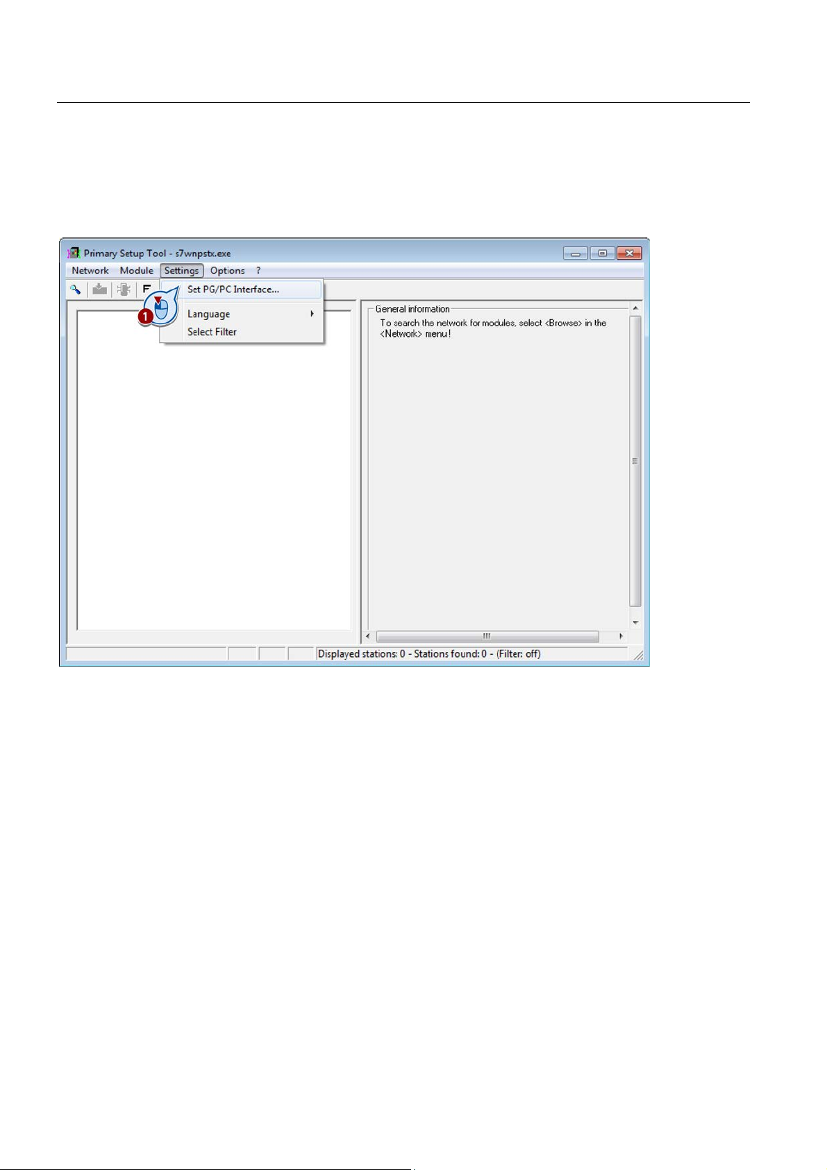
1. Called the Primary Setup Tool.
2. In the Primary Setup Tool select the menu command "Settings > Set PG/PC Interface...".
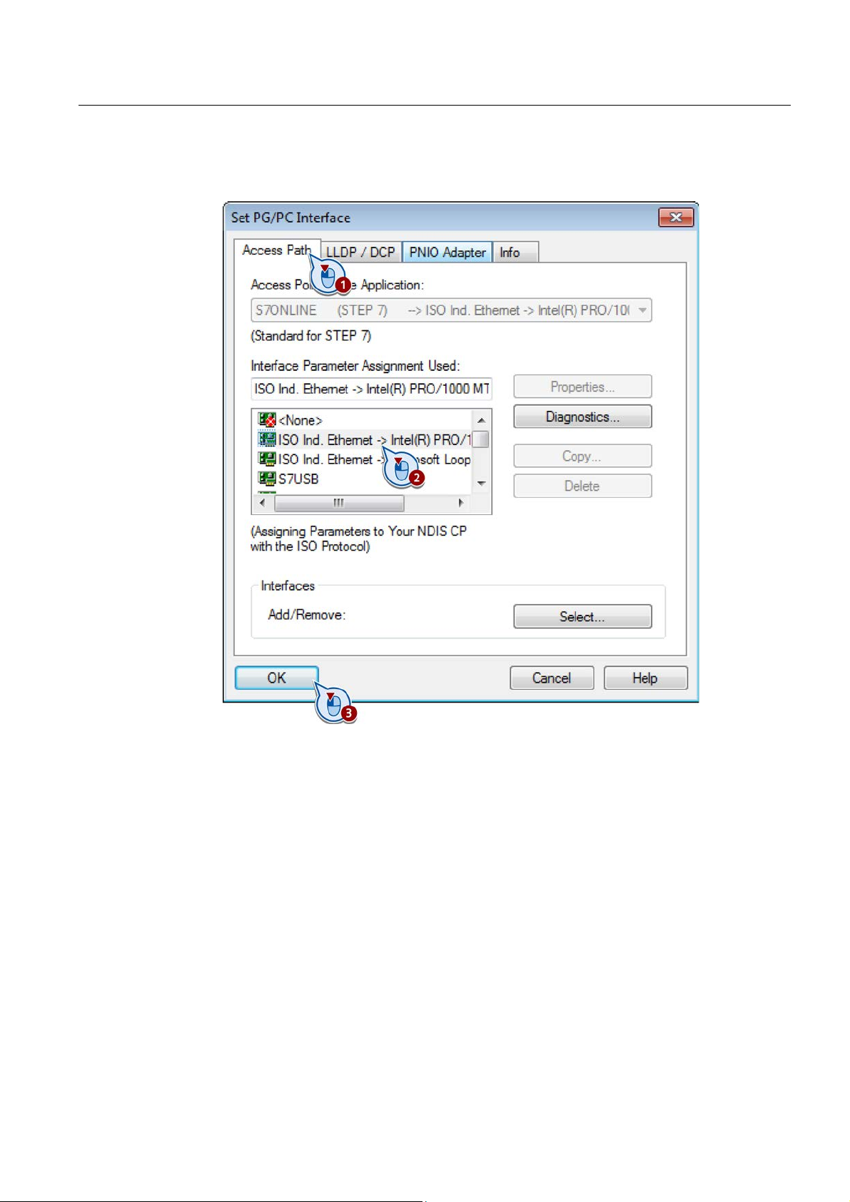
3. In the dialog box "Set PG/PC Interface", select the "Access Path" tab.
SITOP UPS1600 under STEP 7 V5
12 Getting Started,
Page 13
Assigning the IP address
4. From the interfaces listed, select the Ethernet interface with which SITOP UPS1600 is
connected, and confirm with "OK".
SITOP UPS1600 under STEP 7 V5
Getting Started,
13
Page 14
Assigning the IP address
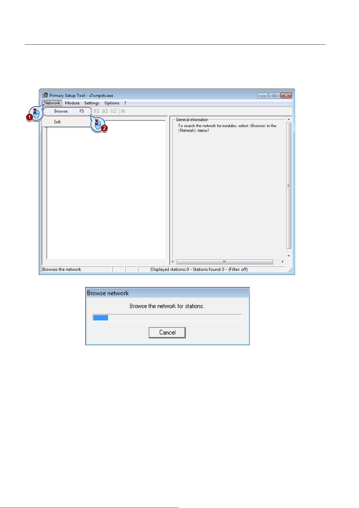
5. Select the menu command "Network > Browse", to view the network stations connected
at the interface.
The "Browse network" window shows the progress of the search
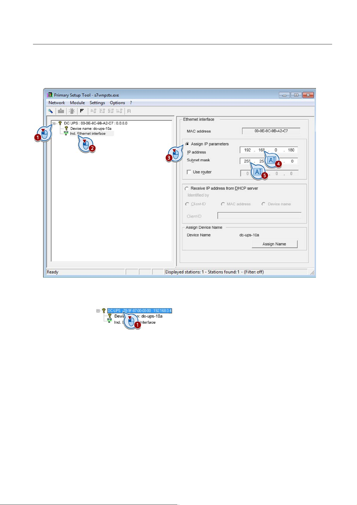
6. From the search results, select the SITOP UPS1600.
The SITOP UPS1600 is displayed as "DC-UPS:" with its MAC address and IP address.
7. Open the menu of the SITOP UPS1600 in the tree view and select "Incl. Ethernet
interface".
8. Select the "Assign IP parameters" checkbox.
SITOP UPS1600 under STEP 7 V5
14 Getting Started,
Page 15
Assigning the IP address
9. Specify the IP address and subnet mask.
If required, select the checkbox "Use router" and enter the IP address of the router.
10. Select the SITOP UPS1600 in the tree view.
The configuration can only be loaded to the device if the SITOP UPS1600 has been
selected at the upper level.
SITOP UPS1600 under STEP 7 V5
Getting Started,
15
Page 16
Assigning the IP address
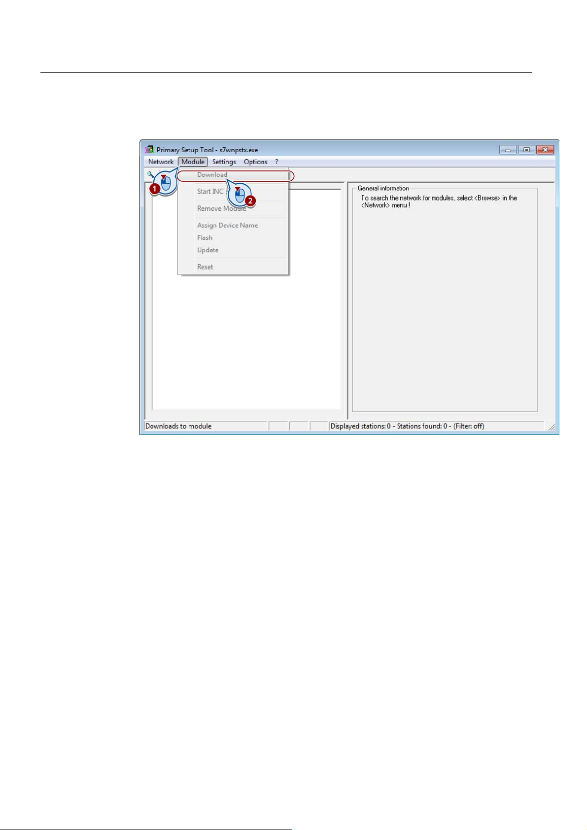
11. In the Primary Setup Tool, select the menu command "Module > Download", to load the
configuration to the SITOP UPS1600.
You have assigned an IP address to the SITOP UPS1600, and you can now communicate
with the SITOP UPS1600.
SITOP UPS1600 under STEP 7 V5
16 Getting Started,
Page 17
STEP 7 V5
5
Preconditions
Placing SITOP UPS1600
● STEP 7 V5 is open and a project with an S7 IO controller has been created.
● The DDF of the UPS1600 is installed correctly.
● The UPS1600 is assigned to an S7 IO controller as IO device.
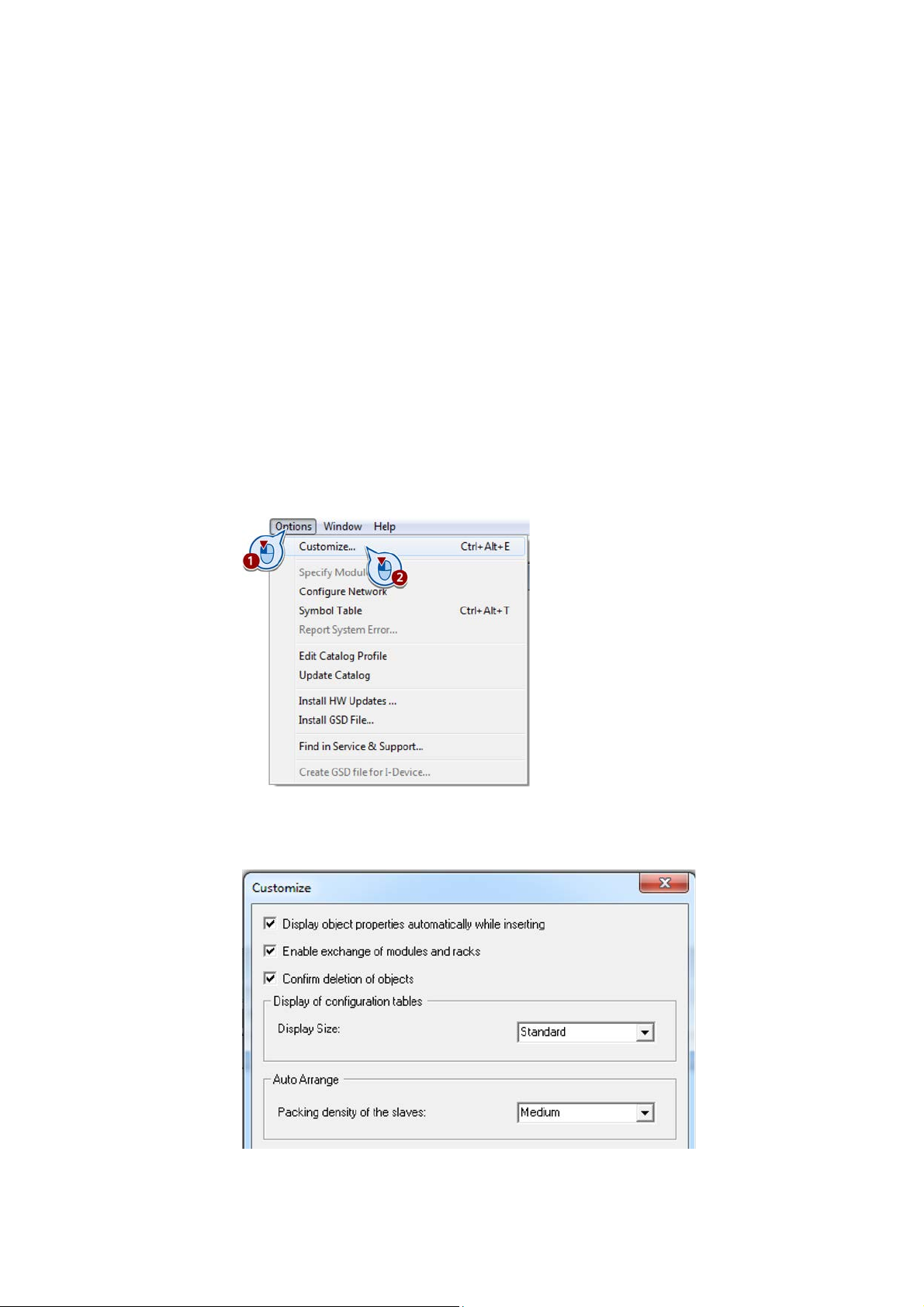
1. Open the "HW Config" window.
2. Select the "Options > Customize..." menu command.
The "Customize" dialog box opens.
3. Check whether the option "Display object properties automatically while inserting" is
active. If necessary, select the checkbox.
SITOP UPS1600 under STEP 7 V5
Getting Started,
17
Page 18
Installing and configuring the SITOP UPS1600 in STEP 7 V5
4. Close the "Customize" dialog box.
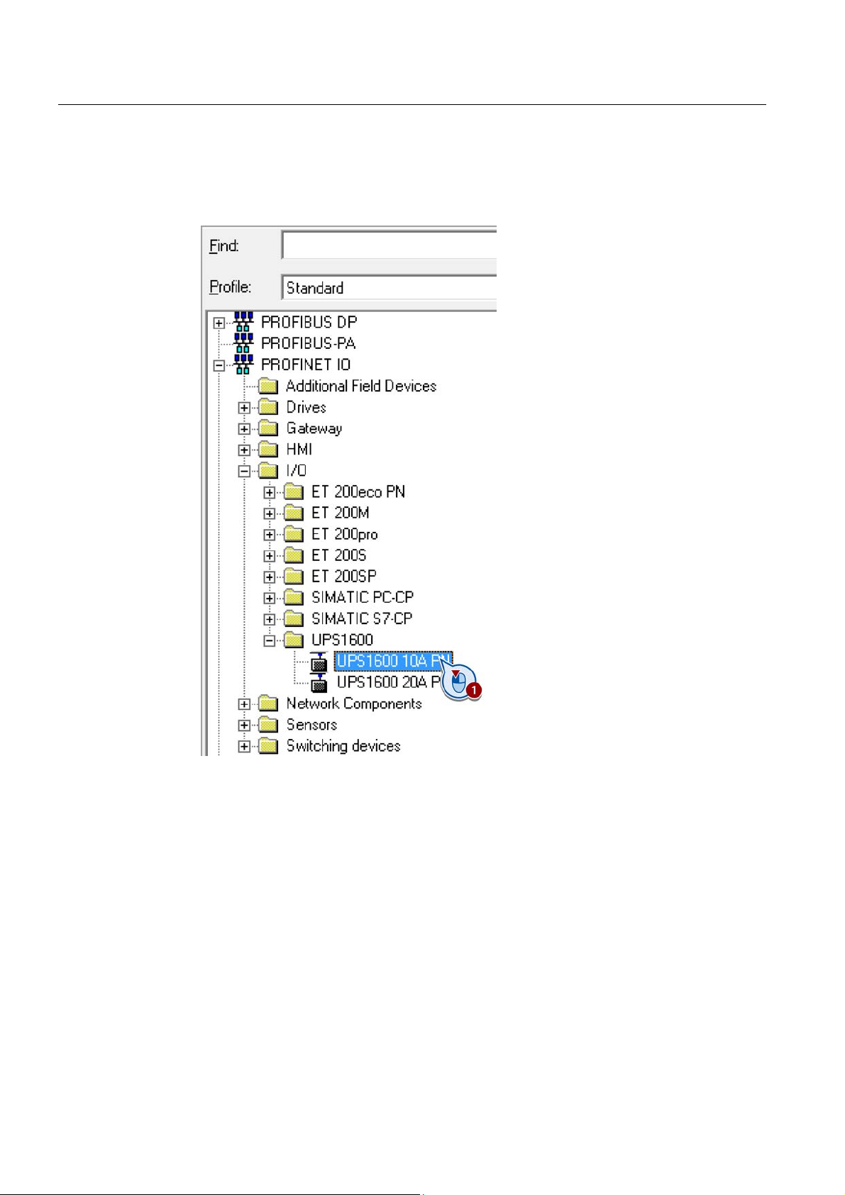
5. Under "PROFINET IO > I/O > UPS1600", select the version of the SITOP UPS1600 being
used.
SITOP UPS1600 under STEP 7 V5
18 Getting Started,
Page 19
Installing and configuring the SITOP UPS1600 in STEP 7 V5
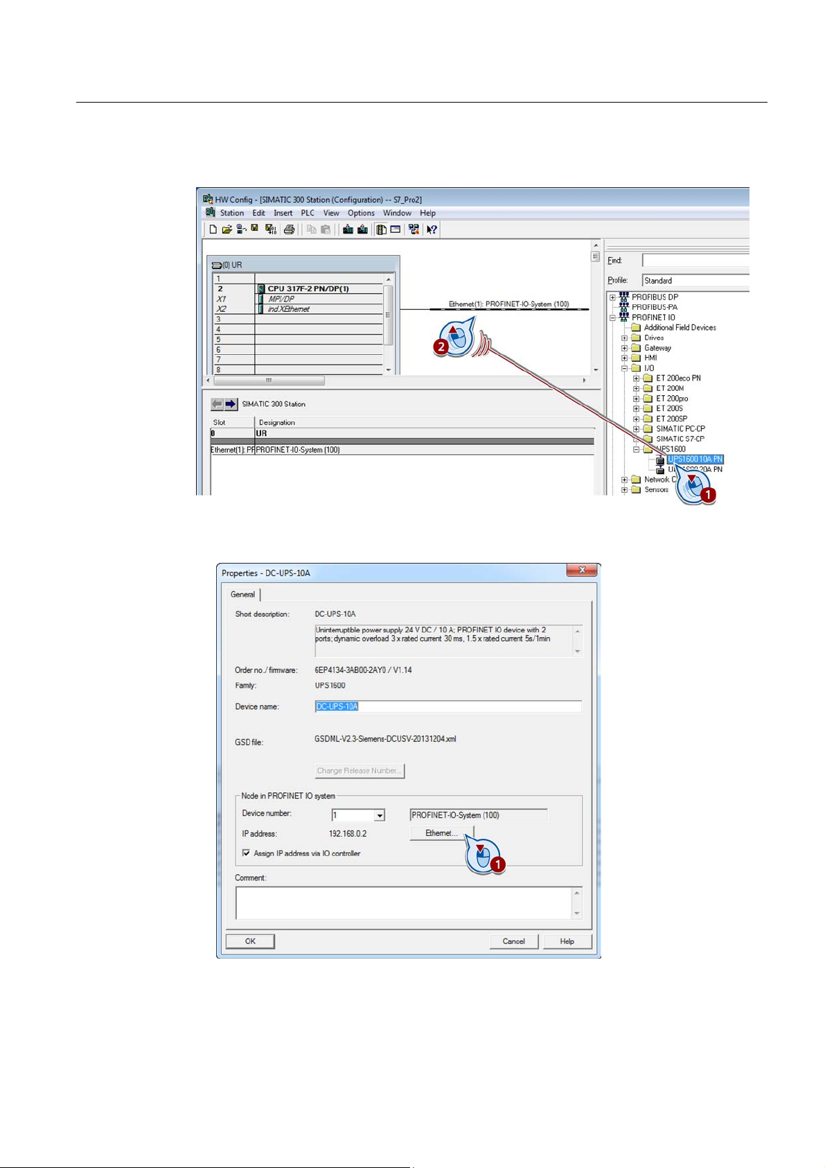
6. Drag and drop the UPS1600 onto the line of the subnet.
The "Properties" dialog box opens.
7. Click on the "Ethernet" button.
The "Properties" subdialog box opens.
SITOP UPS1600 under STEP 7 V5
Getting Started,
19
Page 20
Installing and configuring the SITOP UPS1600 in STEP 7 V5
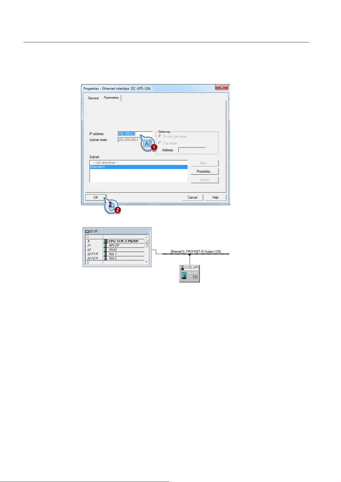
8. Enter an IP address for the UPS1600 at the subnet.
9. Close the two dialog boxes.
The UPS1600 is connected with the subnet.
10. Save your project.
You have placed the UPS1600 and integrated it into the actual project.
SITOP UPS1600 under STEP 7 V5
20 Getting Started,
Page 21

6
6.1
Buffering an S7 IO controller, including the I/O when the power fails
Preconditions
The following examples show you how the uninterruptible SITOP UPS1600 power supply is
parameterized:
● Buffering an S7 IO controller, including the I/O when the power fails
● Switching off the UPS by a user program when the power fails
Parameterizing the uninterruptible SITOP UPS1600 power supply for additional tasks,
please refer to the UPS1600 Manual.
● STEP 7 V5 has been started and a project with an S7 IO controller and SITOP UPS1600
has been opened.
● The hardware has been completely wired up.
SITOP UPS1600 under STEP 7 V5
Getting Started,
21
Page 22
Parameterizing the SITOP UPS1600
Assigning parameters
6.1 Buffering an S7 IO controller, including the I/O when the power fails
1. Change into the "HW Config" window.
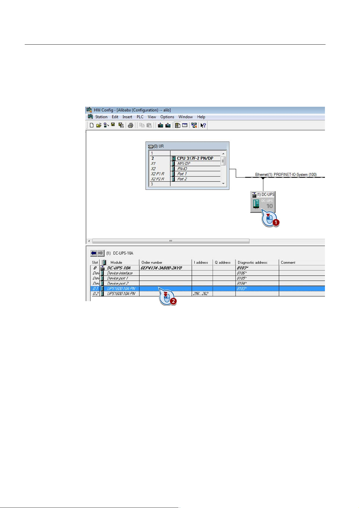
2. Select the UPS1600 and double-click in the configuration table on the upper entry
"UPS1600 10A PN" or "UPS1600 20A PN".
The configuration dialog for the UPS1600 opens.
SITOP UPS1600 under STEP 7 V5
22 Getting Started,
Page 23
Parameterizing the SITOP UPS1600
6.1 Buffering an S7 IO controller, including the I/O when the power fails
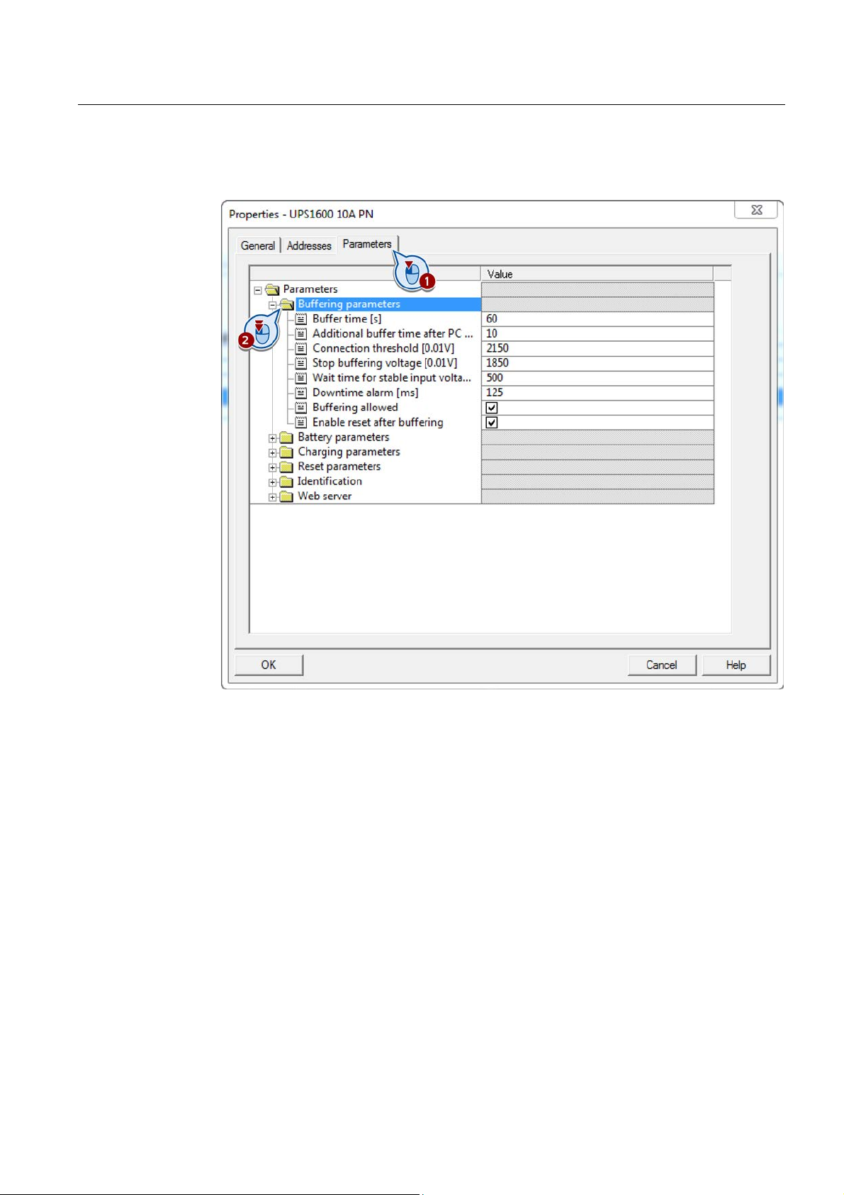
3. In the configuration dialog, go to the "Parameters" tab and open the "Buffering
parameters" folder.
SITOP UPS1600 under STEP 7 V5
Getting Started,
23
Page 24
Parameterizing the SITOP UPS1600
6.1 Buffering an S7 IO controller, including the I/O when the power fails
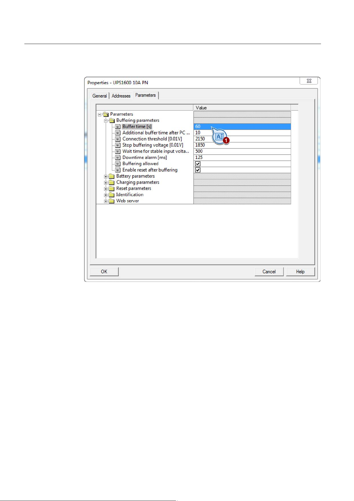
4. Enter the buffer time in "Buffer time".
SITOP UPS1600 under STEP 7 V5
24 Getting Started,
Page 25
Parameterizing the SITOP UPS1600
6.1 Buffering an S7 IO controller, including the I/O when the power fails
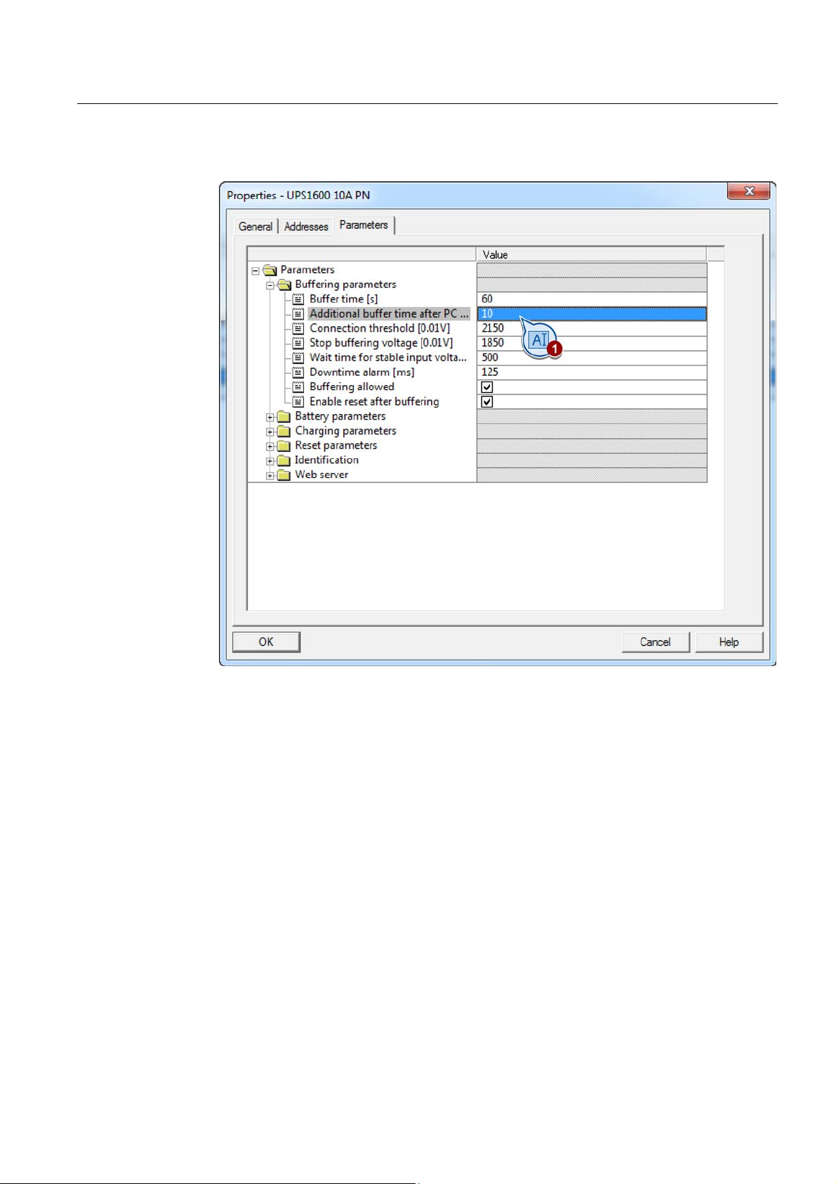
5. Enter "Additional buffer time after PC shutdown".
SITOP UPS1600 under STEP 7 V5
Getting Started,
25
Page 26
Parameterizing the SITOP UPS1600
6.1 Buffering an S7 IO controller, including the I/O when the power fails
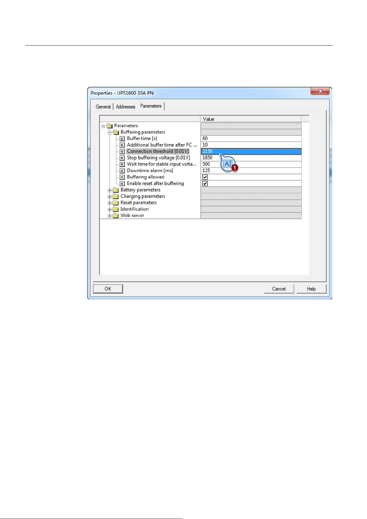
6. For "Connection threshold", enter the voltage value, which, when it is fallen below the
UPS, starts to buffer.
SITOP UPS1600 under STEP 7 V5
26 Getting Started,
Page 27
Parameterizing the SITOP UPS1600
6.1 Buffering an S7 IO controller, including the I/O when the power fails
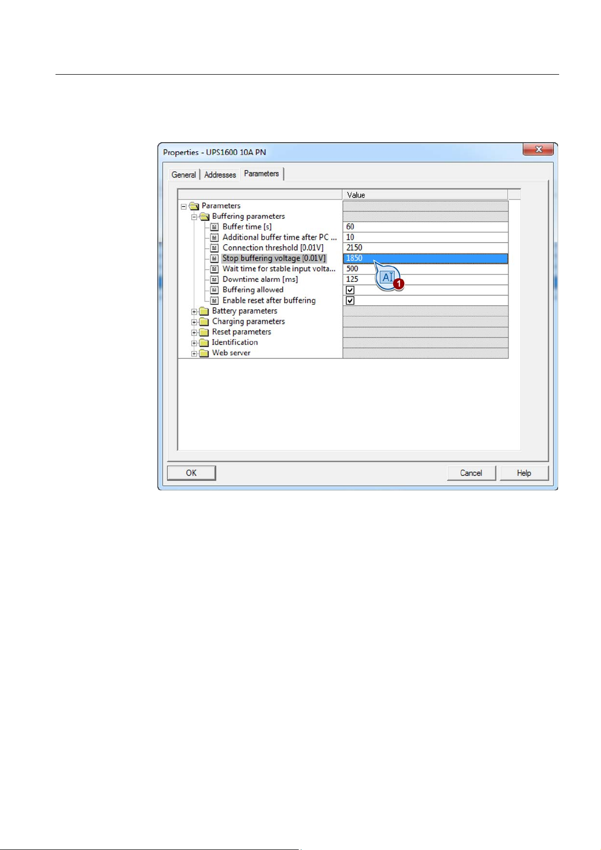
7. Under "Stop buffering voltage" enter the battery voltage value where buffering should be
stopped for a deep discharge condition.
8. Check that "Buffering allowed" is active. If necessary, activate the "Buffering allowed"
checkbox.
SITOP UPS1600 under STEP 7 V5
Getting Started,
27
Page 28
Parameterizing the SITOP UPS1600
6.1 Buffering an S7 IO controller, including the I/O when the power fails
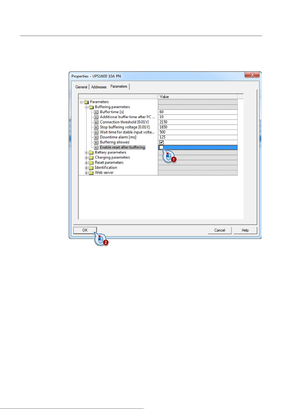
9. Deactivate the checkbox "Enable reset after buffering".
10. Confirm your entries with "OK".
11. Save your project.
12. Load the parameters into the S7 IO controller.
The S7 IO controller including I/O is now buffered when the power fails.
SITOP UPS1600 under STEP 7 V5
28 Getting Started,
Page 29
Parameterizing the SITOP UPS1600
6.2
Switching off the UPS by a user program when the power fails
Content of the code block package
Code block
Name
Description
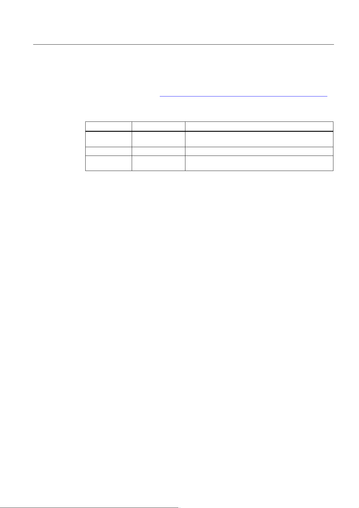
UPS1600
DB160
UPS160_iDB
Instance data block of the FB160
which are displayed within the HMI screen block.
FB160 function description
Notes regarding the function
must be
6.2 Switching off the UPS by a user program when the power fails
To switch off the UPS when the power fails, Siemens provides the FB160 function block in
the Internet under address (http://support.automation/siemens.com/WW/view/en/78817848
).
FB160 UPS1600 Function block for program-controlled shutdown of the
DB161 UPS1600_Infos The data block contains all parameters of the UPS1600,
The FB160 function block cyclically monitors the operating mode of the UPS1600.
The UPS goes into the buffer mode:
● Initially, within the FB160 function block, a timer is started with a time duration of 10
seconds. This prevents that a system is brought into the safe state, even for a short
voltage dip / power failure.
● If the UPS1600 is still in the buffer mode after the timer has expired, FB160 parameter
"UPS_ready_for_reset" parameter is set from "FALSE" to "TRUE".
In the rest of the program execution, this parameter must be used to set all system
sections into a safe state (maintenance setting).
● As soon as the safe state of the system has been established, parameter
"UPS_execute_reset" must be set from "FALSE" to "TRUE" using a signal from the
program execution.
Function block FB160 then sends a command to the UPS1600, which in turn shuts itself
off.
● If the UPS1600 switches back into normal operation while the timer is running, parameter
"UPS_ready_for_reset" is not set. The timer is reset again.
● After parameter "UPS_execute_reset" has been set, the rest of the program sequence
executed by function block FB160 until the UPS1600 is shut down.
SITOP UPS1600 under STEP 7 V5
Getting Started,
29
Page 30
Parameterizing the SITOP UPS1600
Preconditions
Loading the block library into STEP 7 V5
6.2 Switching off the UPS by a user program when the power fails
The following preconditions must be fulfilled in order to be able to use function block FB160:
● The library with the function block has been downloaded to the PC.
● The generic station description (GSD) for the UPS1600 has been installed in STEP 7 V5.
● The UPS1600 has been set up for buffer operation (see Chapter Buffering an S7 IO
controller, including the I/O when the power fails (Page 21)).
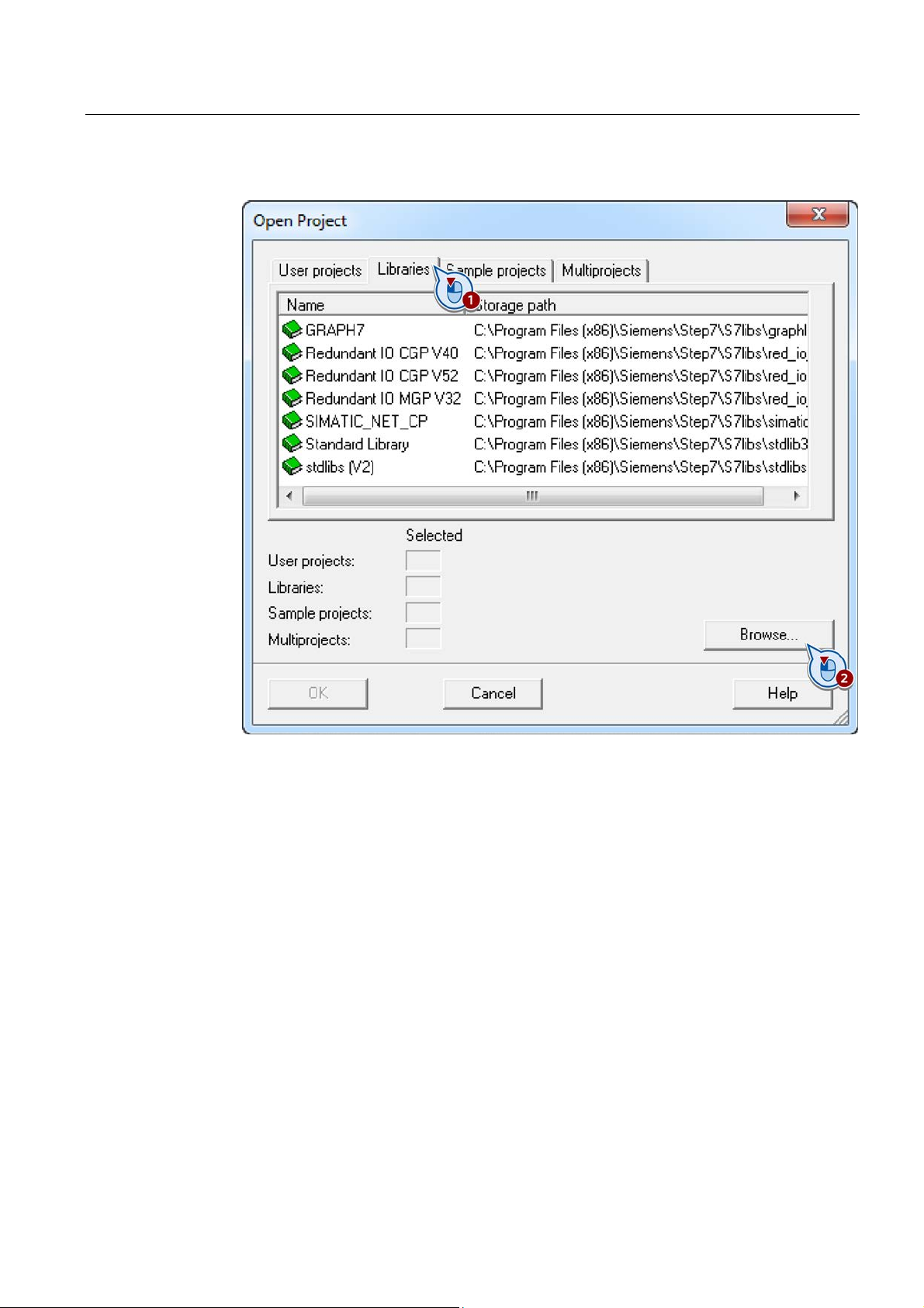
1. Open the project into which the FB160 function block should be inserted.
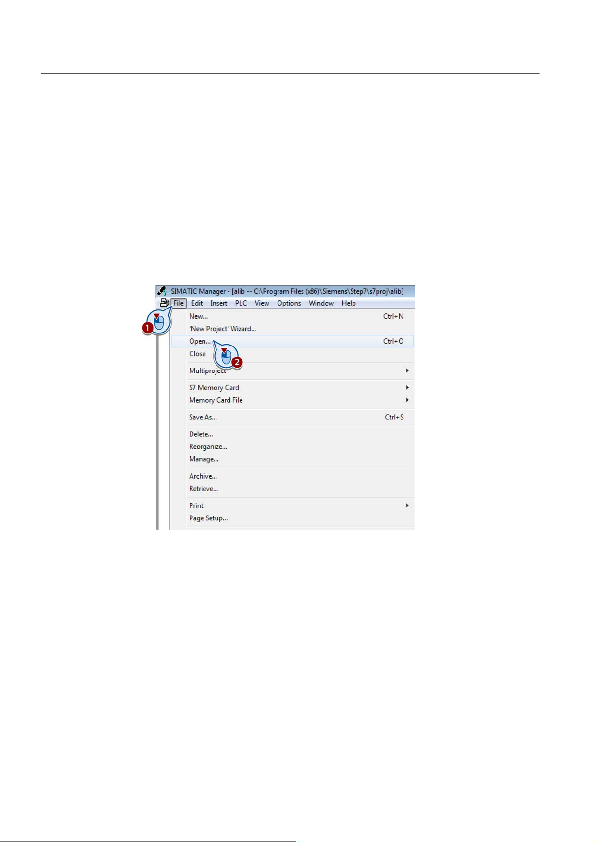
2. Select the menu command "File > Open...".
Dialog box "Open Project" is opened.
SITOP UPS1600 under STEP 7 V5
30 Getting Started,
Page 31
Parameterizing the SITOP UPS1600
6.2 Switching off the UPS by a user program when the power fails
3. Go to the "Libraries" tab and click on "Browse".
The "Browse" dialog opens.
SITOP UPS1600 under STEP 7 V5
Getting Started,
31
Page 32
Parameterizing the SITOP UPS1600
6.2 Switching off the UPS by a user program when the power fails
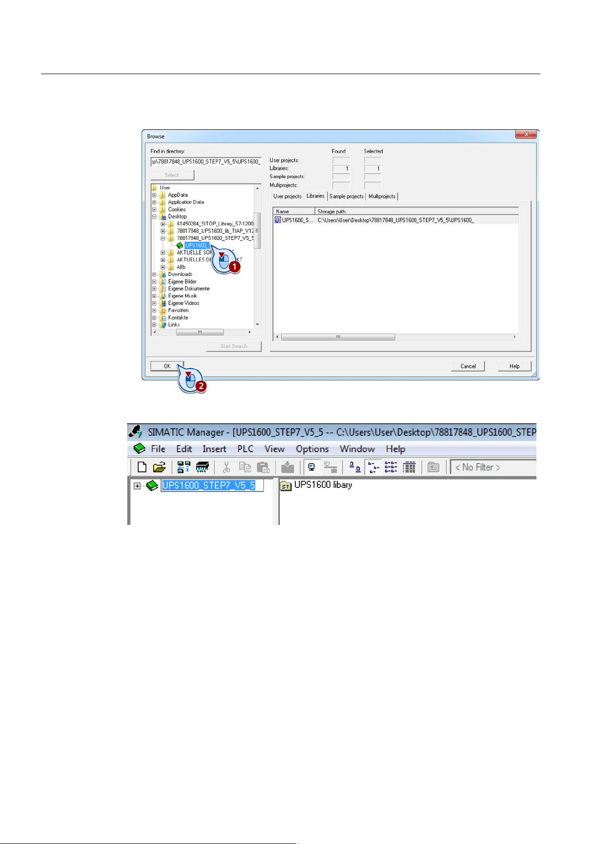
4. Select where library "UPS1600 STEP7 V5_5" is located and confirm with "OK".
The library is loaded.
SITOP UPS1600 under STEP 7 V5
32 Getting Started,
Page 33
Parameterizing the SITOP UPS1600
Integrating function block FB160 into a project
6.2 Switching off the UPS by a user program when the power fails
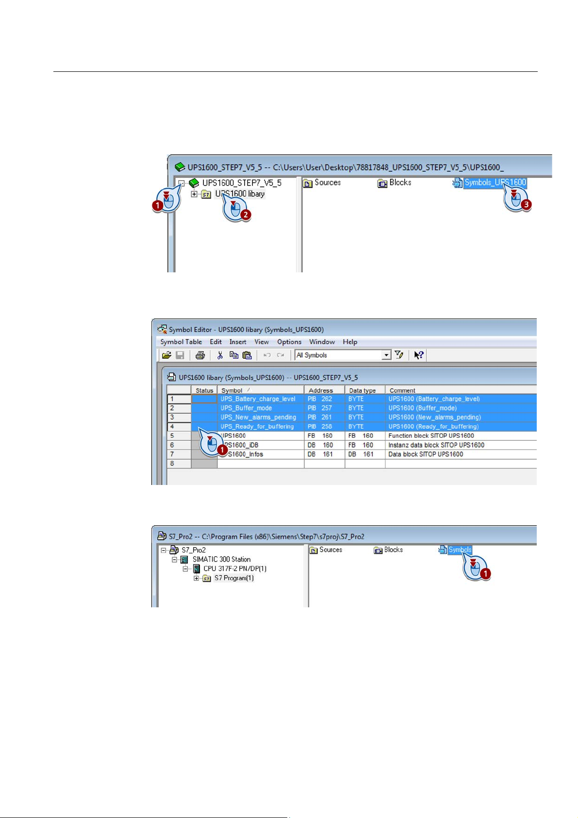
1. Open the library, select program folder "UPS1600 library" and open the symbol table
"Symbols_UPS1600".
2. With the mouse key pressed, move over the 4 lines "UPS_Battery_charge_level",
"UPS_Buffer_mode", UPS_New_alarms_pending" and "UPS_Ready_for_buffering", to
select them.
3. Copy the four selected entries into the clipboard.
4. Open the symbol table "Symbols" in your target project.
5. Copy the four lines from the template into the table.
SITOP UPS1600 under STEP 7 V5
Getting Started,
33
Page 34
Parameterizing the SITOP UPS1600
6.2 Switching off the UPS by a user program when the power fails
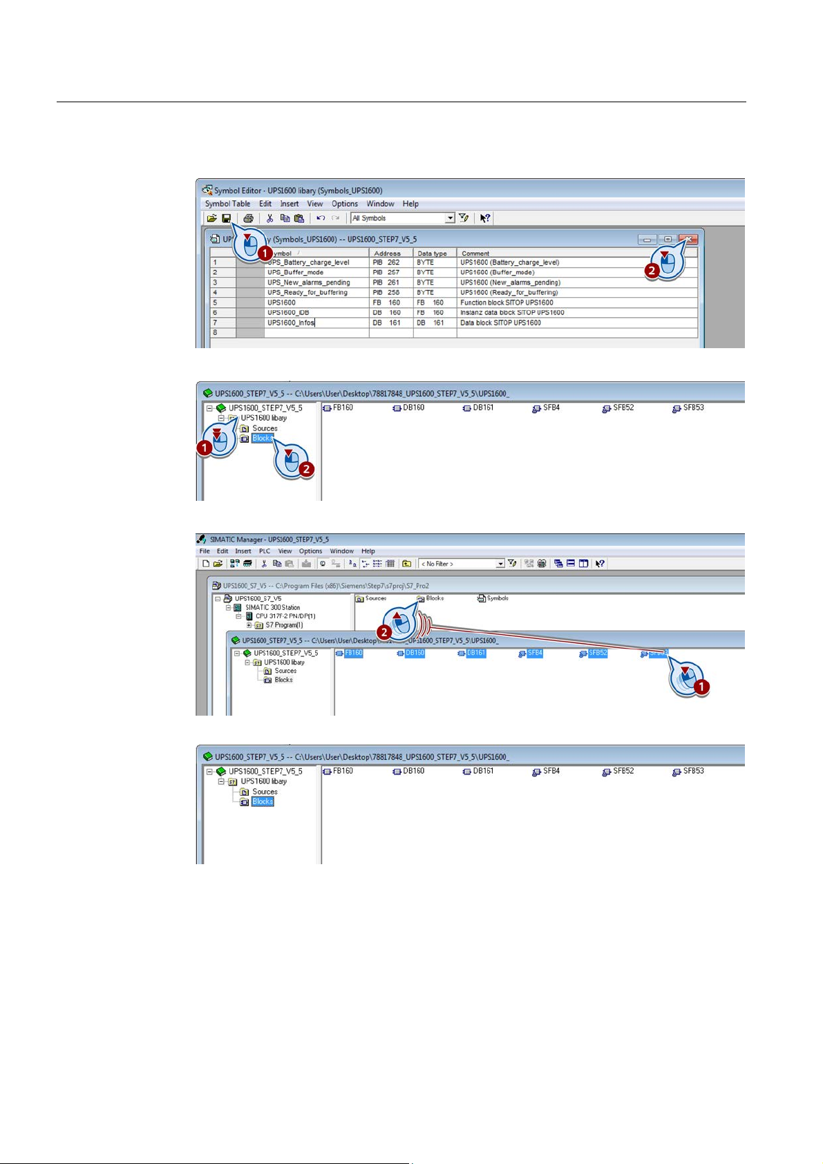
6. Save the table and close the symbol Editor.
7. Open the library "UPS1600 library > Blocks".
8. Select all blocks, drag them and drop them in the "Blocks" folder of your target project.
The blocks are inserted into your target project.
Function block FB160 has now been integrated into the project.
SITOP UPS1600 under STEP 7 V5
34 Getting Started,
Page 35
Parameterizing the SITOP UPS1600
Calling function block FB160
Note
Ensure that the update cycle of the organization block being used has a direct influence on
the update time of the function block.
6.2 Switching off the UPS by a user program when the power fails
Calling the function block within an organization block (OB) is described in the following. In
this case, function block FB160 is called within organization block OB1.
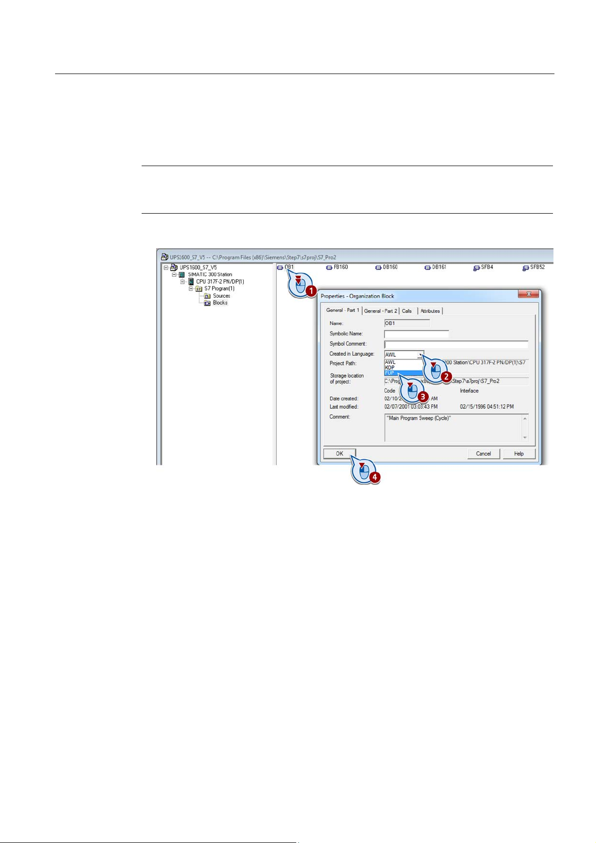
1. In the "Blocks" folder of your project, open block "Main [OB1]" in the FBD view.
SITOP UPS1600 under STEP 7 V5
Getting Started,
35
Page 36
Parameterizing the SITOP UPS1600
6.2 Switching off the UPS by a user program when the power fails
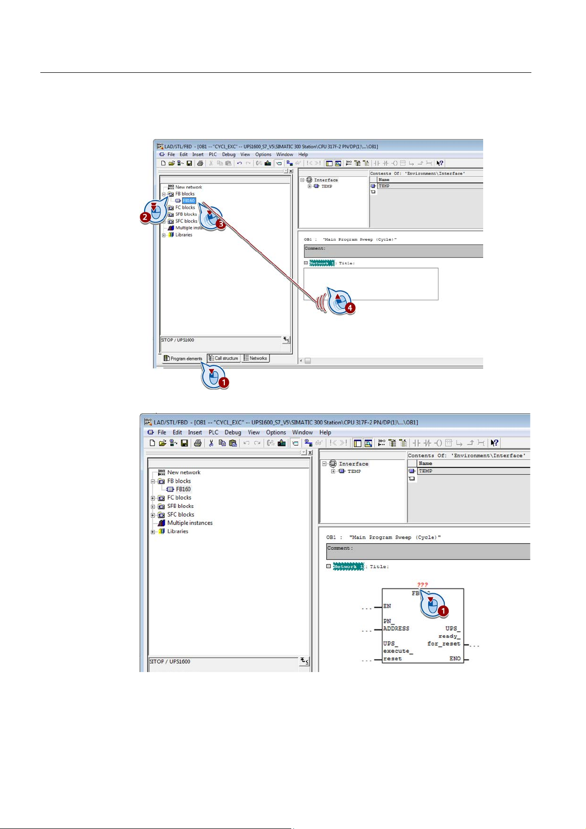
2. Change to the "Program elements" tab, open the folder "FB blocks", drag block "FB160"
and drop it into an empty network of "Main [1]".
3. Click on the 3 question marks above function block "FB160" that has been inserted.
SITOP UPS1600 under STEP 7 V5
36 Getting Started,
Page 37
Parameterizing the SITOP UPS1600
UPS1600 diagnostic address
8183
Entry at PN_address
DW#16#1FF7
6.2 Switching off the UPS by a user program when the power fails
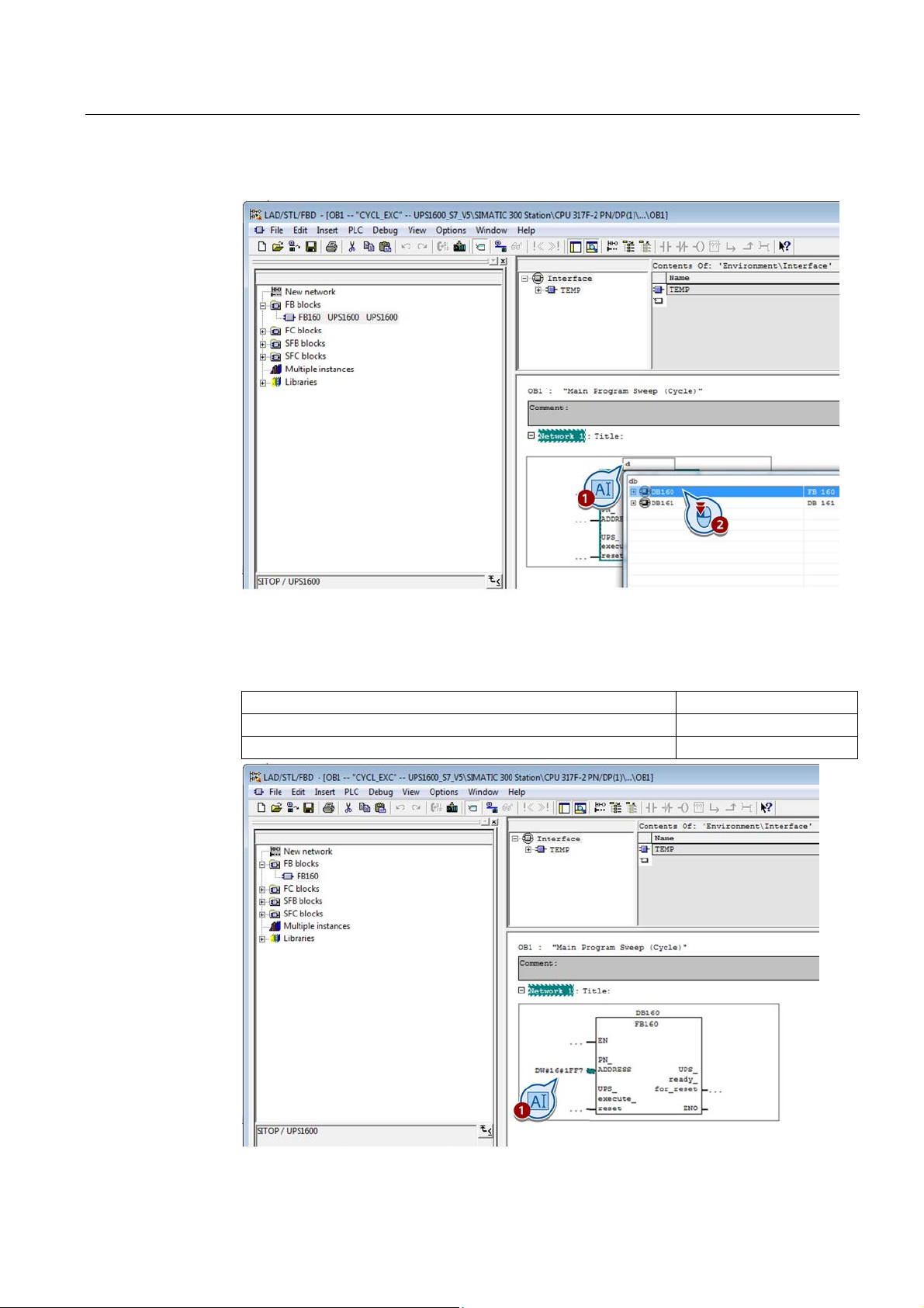
4. Enter a letter "d" into the field, and select "DB160" from the window that then opens.
5. At block parameter "PN_ADDRESS", first enter "DW#16#" followed directly by the
Profinet diagnostic address of the UPS1600 in your STEP 7 project in hexadecimal form.
Example:
Hexadecimal diagnostic address 1FF7
SITOP UPS1600 under STEP 7 V5
Getting Started,
37
Page 38
Parameterizing the SITOP UPS1600
Parameters
Declaration
Data type
Description
UPS1600
UPS_ready_for_reset
Output
Bool
Signal to run down the system
6.2 Switching off the UPS by a user program when the power fails
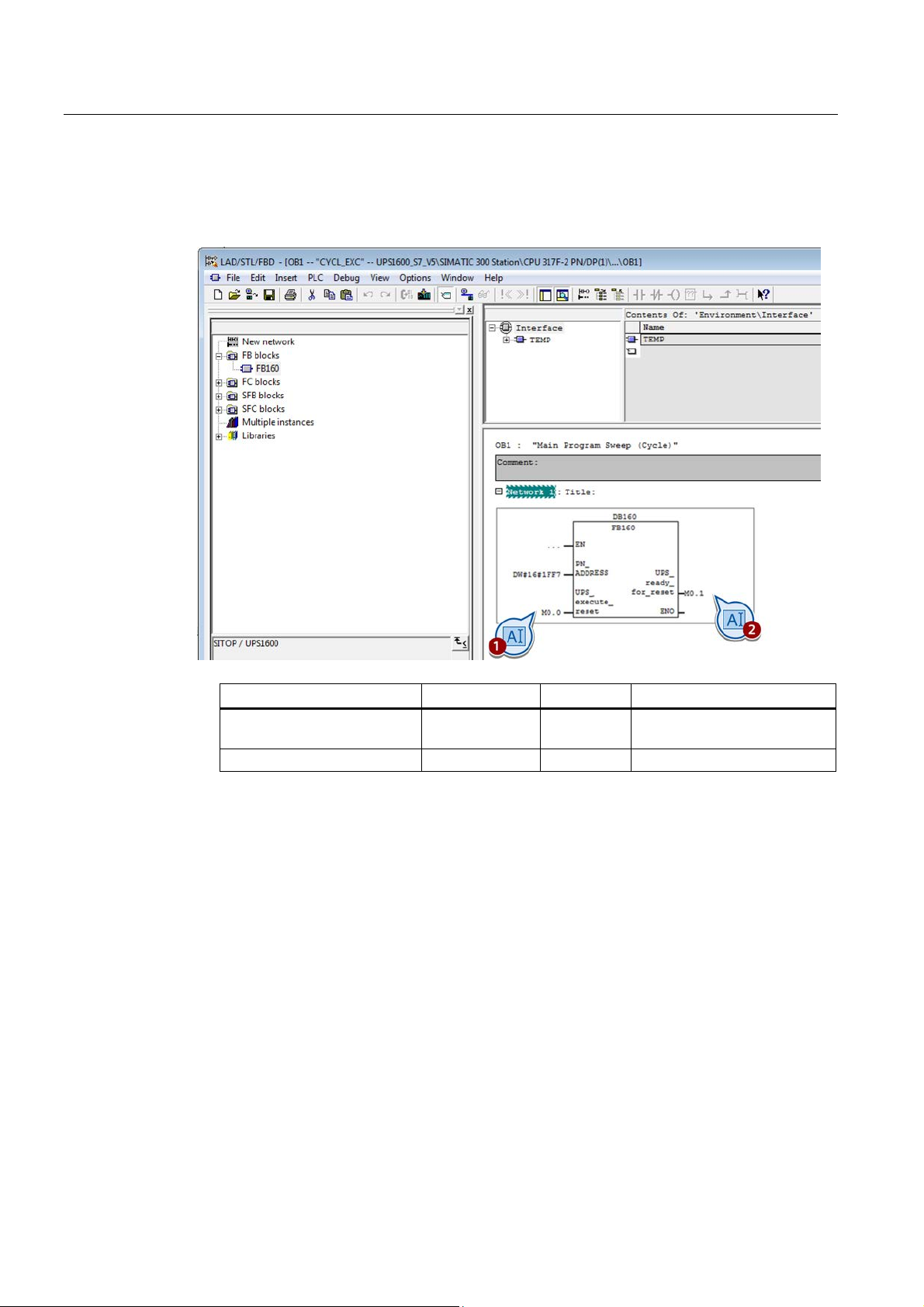
6. Connect block parameters "UPS_execute_reset" and "UPS_ready_for_reset" (for a
description of the parameters, refer to the table below).
Example: Bit memory "M0.0" or "M0.1" is set for the block parameters.
UPS_execute_reset Input Bool Shutdown signal at the
7. Save your project.
SITOP UPS1600 under STEP 7 V5
38 Getting Started,
Page 39

Parameterizing the SITOP UPS1600
Adapting the symbol table/address area
Note
You can find the setting of the I/O address area for the UPS1600 in the HW Config of
Simatic station that you created.
Variable in the symbol table
UPS1600 parameters
Information
Address area in the
following example
the battery
alarms
Note
You can find additional information on the I/O address
Manual.
6.2 Switching off the UPS by a user program when the power fails
When function block FB160 is executed, the cyclic data of address area of UPS1600 is
accessed. In this particular case, the required address areas are transferred to the function
block via four variables. You must adapt the addresses of these variables corresponding to
your selected address area in the symbol table of the code block package.
The following table shows the I/O address area of the UPS1600, which is used within the
function block.
the
UPS_battery_charge_level battery_charge level Charging state of
UPS_Buffer_mode buffer mode Buffer mode/
normal mode
UPS_New_alarms_pending New alarms pending New / no pending
UPS_Ready_for_buffering ready for buffering Ready for
buffering / not
ready
PEB 262
PEB 257
PEB 261
PEB 258
area of the UPS1600 in the UPS1600
SITOP UPS1600 under STEP 7 V5
Getting Started,
39
Page 40
Parameterizing the SITOP UPS1600
Procedure
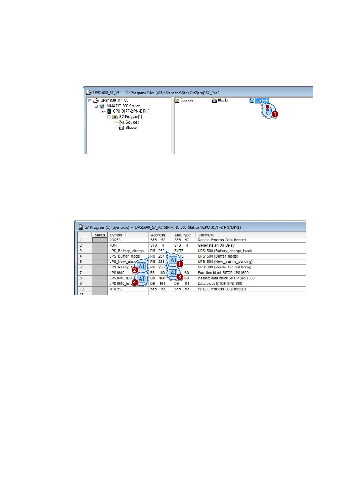
6.2 Switching off the UPS by a user program when the power fails
1. In the program folder of your project, open the symbol table "Symbols_UPS1600".
2. Match the addresses of the following symbols with the selected I/O address areas of the
corresponding UPS1600 parameters:
– UPS_Battery_charge_level
– UPS_Buffer_mode
– UPS_New_alarms_pending
– UPS_Ready_for_buffering
3. Save the project and load the parameters into the S7 IO controller.
When the power fails, the user program now switches off the UPS.
SITOP UPS1600 under STEP 7 V5
40 Getting Started,
 Loading...