

Page 1
Industrial Controls
SIRIUS
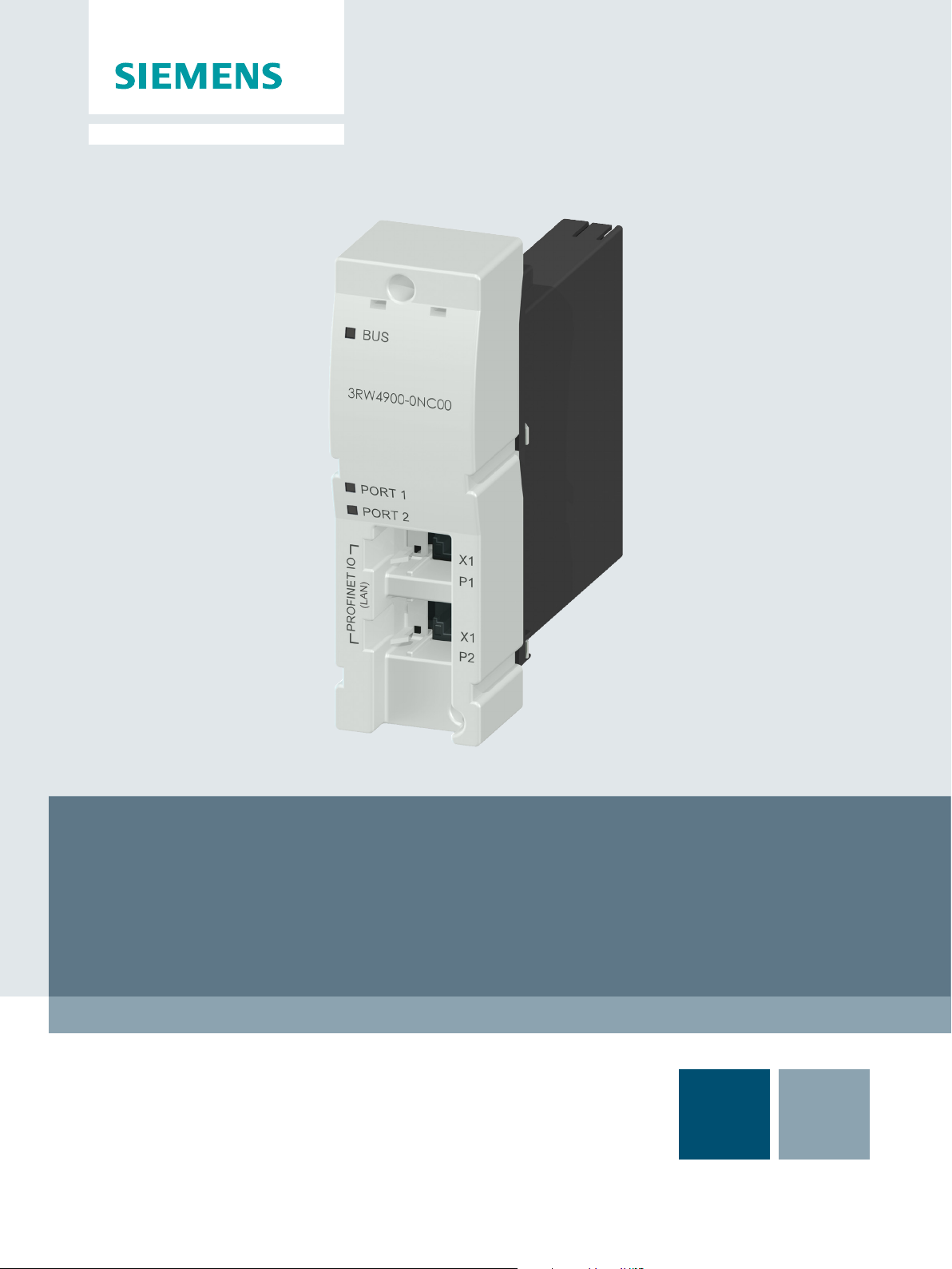
PROFINET Communication Module for SIRIUS Soft Starter 3RW44
GerätehandbuchManual
Edition
Answers for industry.
12/2013
Page 2

Page 3
PROFINET Communication Module for
SIRIUS Soft Starter 3RW44
___________________
___________________
___________________
___________________
___________________
___________________
___________________
___________________
Industrial Controls
SIRIUS
PROFINET Communication Module
for SIRIUS Soft Starter 3RW44
Manual
12/2013
Introduction
1
Safety information
2
Product description
3
Installation / removal
4
Configuring/assigning
parameters
5
Commissioning
6
Functions
7
Technical specifications
8
Dimension drawings
9
Circuit diagram example
10
Appendix
A
___________________
___________________
___________________
A5E31996495002A/RS-AA/001
Page 4
Warning notice system
DANGER
will
WARNING
may
CAUTION
NOTICE
Qualified Personnel
personnel qualified
Proper use of Siemens products
WARNING
maintenance are required to ensure that the products operate safely and without any problems. The permissible
Trademarks
Disclaimer of Liability
Legal information
This manual contains notices you have to observe in order to ensure your personal safety, as well as to prevent
damage to property. The notices referring to your personal safety are highlighted in the manual by a safety alert
symbol, notices referring only to property damage have no safety alert symbol. These notices shown below are
graded according to the degree of danger.
indicates that death or severe personal injury
indicates that death or severe personal injury
indicates that minor personal injury can result if proper precautions are not taken.
indicates that property damage can result if proper precautions are not taken.
If more than one degree of danger is present, the warning notice representing the highest degree of danger will
be used. A notice warning of injury to persons with a safety alert symbol may also include a warning relating to
property damage.
The product/system described in this documentation may be operated only by
task in accordance with the relevant documentation, in particular its warning notices and safety instructions.
Qualified personnel are those who, based on their training and experience, are capable of identifying risks and
avoiding potential hazards when working with these products/systems.
result if proper precautions are not taken.
result if proper precautions are not taken.
for the specific
Note the following:
Siemens products may only be used for the applications described in the catalog and in the relevant technical
documentation. If products and components from other manufacturers are used, these must be recommended
or approved by Siemens. Proper transport, storage, installation, assembly, commissioning, operation and
ambient conditions must be complied with. The information in the relevant documentation must be observed.
All names identified by ® are registered trademarks of Siemens AG. The remaining trademarks in this publication
may be trademarks whose use by third parties for their own purposes could violate the rights of the owner.
We have reviewed the contents of this publication to ensure consistency with the hardware and software
described. Since variance cannot be precluded entirely, we cannot guarantee full consistency. However, the
information in this publication is reviewed regularly and any necessary corrections are included in subsequent
editions.
Siemens AG
Industry Sector
Postfach 48 48
90026 NÜRNBERG
GERMANY
3ZX1012-0RW40-0AC0
Ⓟ 12/2013 Technical data subject to change
Copyright © Siemens AG 2013.
All rights reserved
Page 5

Table of Contents
1 Introduction................................................................................................................................... 9
2 Safety information ....................................................................................................................... 13
3 Product description ...................................................................................................................... 17
4 Installation / removal .................................................................................................................... 23
5 Configuring/assigning parameters ................................................................................................. 27
6 Commissioning ........................................................................................................................... 31
7 Functions ................................................................................................................................... 43
1.1 Important notes ........................................................................................................................ 9
2.1 Security information ................................................................................................................ 13
2.2 Before commencing work: Isolating the equipment from the supply system and ensuring
that it cannot be reconnected.................................................................................................. 13
2.3 Data security in automation .................................................................................................... 14
3.1 Fieldbus interfaces ................................................................................................................. 18
3.1.1 PROFINET IO ........................................................................................................................ 18
3.2 Communication principle ........................................................................................................ 20
3.3 Display when PROFINET communication module is activated ................................................ 21
3.4 Fieldbus for PROFINET menu structure.................................................................................. 22
4.1 Inserting the PROFINET communication module .................................................................... 23
4.2 Ethernet cable to RJ45 socket ................................................................................................ 25
4.3 Removal of the PROFINET communication module ................................................................ 25
5.1 Configuring soft starters ......................................................................................................... 27
5.1.1 Configuring with a GSD file ..................................................................................................... 27
5.1.2 Assigning parameters with the "Soft Starter ES 2007" software .............................................. 27
5.1.3 Diagnostics package .............................................................................................................. 28
5.2 Configuring the properties of 3RW44 PN as IO device ............................................................ 28
6.1 Activation of the PROFINET communication module via the display ....................................... 31
6.1.1 Activation of the fieldbus interface .......................................................................................... 32
6.1.2 Saving settings retentively ...................................................................................................... 33
6.2 Activation of the PROFINET communication module via software ........................................... 34
6.3 Parameter settings in the soft starter under Fieldbus .............................................................. 36
7.1 PROFIenergy ......................................................................................................................... 43
7.1.1 Energy saving function command ........................................................................................... 44
7.1.2 Measured value function command ........................................................................................ 46
7.1.3 Function blocks for SIMATIC S7 ............................................................................................. 46
PROFINET Communication Module for SIRIUS Soft Starter 3RW44
Manual, 12/2013, A5E31996495002A/RS-AA/001
5
Page 6

Table of Contents
8 Technical specifications ............................................................................................................... 67
9 Dimension drawings .................................................................................................................... 69
10 Circuit diagram example .............................................................................................................. 73
A Appendix ................................................................................................................................... 75
7.2 OPC UA server .......................................................................................................................47
7.2.1 Features of OPC UA ...............................................................................................................47
7.2.2 Reading and writing data .........................................................................................................48
7.2.3 Activating the OPC UA server .................................................................................................48
7.2.4 Setting the IP parameters ........................................................................................................49
7.2.5 Access to the OPC UA server .................................................................................................50
7.2.6 Establishing a connection to the OPC UA server .....................................................................52
7.2.7 Connection monitoring ............................................................................................................53
7.3 Web server .............................................................................................................................54
7.3.1 Contents of web pages ............................................................................................................54
7.3.2 Activating the web server ........................................................................................................54
7.3.3 Setting the IP parameters ........................................................................................................55
7.3.4 Access to the web server ........................................................................................................56
7.3.5 Establishing a connection to the web server ............................................................................56
7.4 Time synchronization ..............................................................................................................57
7.5 SNMP .....................................................................................................................................58
7.6 Diagnostic functions ................................................................................................................59
7.6.1 Diagnostics of the communication module via LED display ......................................................59
7.6.2 Diagnostics with STEP 7 .........................................................................................................60
7.6.2.1 Evaluation of interrupts with PROFINET IO .............................................................................60
7.6.2.2 Error types ..............................................................................................................................61
7.6.3 Diagnostics and alarms ...........................................................................................................62
7.7 Firmware update of the PROFINET communication module ....................................................63
7.8 Factory settings .......................................................................................................................65
8.1 Conditions for storage and operation .......................................................................................67
8.2 Standards and approvals .........................................................................................................67
9.1 PROFINET communication module .........................................................................................69
9.2 PROFINET communication module with connectors ................................................................70
A.1 Data formats and data records ................................................................................................75
A.1.1 Process data and process images ...........................................................................................75
A.1.2 Data record 68 - Read/write process image of the outputs (PIO) ..............................................80
A.1.3 Data record 69 - Process image of the inputs (PII) ...................................................................82
A.1.4 Data record 72 - Log list - Read device error ...........................................................................83
A.1.5 Data record 73 - Log list - Read trips .......................................................................................84
A.1.6 Data record 75 - Log list - Read events....................................................................................85
A.1.7 Data record 81 - Read basic setting of data record 131 ...........................................................86
A.1.8 Data record 82 - Read basic setting of data record 132 ...........................................................86
A.1.9 Data record 83 - Read basic setting of data record 133 ...........................................................87
A.1.10 Data record 92 - Read device diagnostics................................................................................87
A.1.11 Data record 93 - Write commands ...........................................................................................93
A.1.12 Data record 94 - Read measured values .................................................................................94
PROFINET Communication Module for SIRIUS Soft Starter 3RW44
6 Manual, 12/2013, A5E31996495002A/RS-AA/001
Page 7

Table of Contents
Glossary ................................................................................................................................... 115
Index ....................................................................................................................................... 119
A.1.13 Data record 95 - Read statistical data ..................................................................................... 95
A.1.14 Data record 96 - Read maximum pointer ................................................................................ 96
A.1.15 Data records 131, 141, 151 - Technology parameter 2: Read/write record 1, 2, 3.................... 97
A.1.16 Data records 132, 142, 152 - Technology parameter 3: Read/write record 1, 2, 3.................. 102
A.1.17 Data record 133 - Technology parameter 4: OCM module .................................................... 102
A.1.18 Data record 165 - Read/write comment ................................................................................ 103
A.1.19 OPC UA variables ................................................................................................................ 104
A.2 List of abbreviations ............................................................................................................. 110
A.3 Correction sheet ................................................................................................................... 113
PROFINET Communication Module for SIRIUS Soft Starter 3RW44
Manual, 12/2013, A5E31996495002A/RS-AA/001
7
Page 8

Table of Contents
PROFINET Communication Module for SIRIUS Soft Starter 3RW44
8 Manual, 12/2013, A5E31996495002A/RS-AA/001
Page 9

1
1.1
Important notes
Purpose of this manual
Target group
Required basic knowledge
Scope
This manual contains the basics for using SIRIUS 3RW44 soft starters in conjunction with
the PROFINET communication module. The soft starter can be optionally expanded to
include a PROFIBUS or PROFINET communication module. The PROFINET communication
module allows a 3RW44 soft starter to be connected to the PROFINET communication
system.
The SIRIUS 3RW44 soft starter is an electronic motor controller that enables optimized
starting and stopping of three-phase asynchronous motors.
This manual describes all functions of the PROFINET communication module.
This manual is intended for all users involved in
● Commissioning
● Service and maintenance
● Planning and configuring plants
General knowledge of the following areas is needed in order to understand the manual:
● General electrical engineering
● STEP 7
This manual is valid for the PROFINET 3RW4900-0NC00 communication module for SIRIUS
3RW44 soft starters. It contains a description of the components applicable at the time of
printing the manual. SIEMENS reserves the right to provide updated information about new
components or new versions of components in a product information document.
PROFINET Communication Module for SIRIUS Soft Starter 3RW44
Manual, 12/2013, A5E31996495002A/RS-AA/001
9
Page 10

Introduction
Short designations and their meaning
Short designation
Meaning
Other publications
Standards and approvals
Disclaimer of liability
1.1 Important notes
3RW44 SIRIUS 3RW44 soft starter
3RW44 PN SIRIUS 3RW44 soft starter with activated PROFINET 3RW4900-0NC00 communication
module
● Operating instructions "PROFINET Communication Module for Soft Starter 3RW44",
order no.: 3ZX1012-0RW40-0NA1
● Manual "3RW44 Soft Starters", order no.: 3ZX1012-0RW44-1AB1
(http://support.automation.siemens.com/WW/view/de/21772518)
● Operating instructions "Soft Starter 3RW44", order no.: 3ZX1012-0RW44-0AA0
(http://support.automation.siemens.com/WW/view/de/21189750)
The SIRIUS 3RW44 soft starter is based on IEC/EN 60947-4-2.
It is the responsibility of the manufacturer to ensure that a system or machine is functioning
properly as a whole. SIEMENS AG, its regional offices, and associated companies
(hereinafter referred to as "SIEMENS") cannot guarantee all the properties of a complete
plant or machine that has not been designed by SIEMENS.
Similarly, SIEMENS can assume no liability for recommendations that appear or are implied
in the following description. No new guarantee, warranty, or liability claims beyond the scope
of the SIEMENS general terms of supply are to be derived or inferred from the following
description.
PROFINET Communication Module for SIRIUS Soft Starter 3RW44
10 Manual, 12/2013, A5E31996495002A/RS-AA/001
Page 11

Introduction
Up-to-the-minute information
Technical assistance:
Correction sheet
1.1 Important notes
Your regional contact for low-voltage switchgear with communications capability will be
happy to help you with any queries you have regarding the soft starters. A list of contacts
and the latest version of the manual are available on the Internet
(http://www.siemens.com/softstarter).
For all technical queries, please contact:
Phone: +49 (911) 895-5900 (8:00 – 17:00 CET)
Fax: +49 (911) 895-5907
Mailing address:
SIEMENS AG
Technical Assistance
Würzburger Str. 121
D-90766 Fürth, Germany
Internet: (http://www.siemens.com/sirius/technical-assistance)
Email: (mailto:[email protected])
A correction sheet is included at the end of this manual. Please use it to enter your
suggestions for improvements, additions and corrections, and send it back to us. This will
help us to improve the next edition of the manual.
PROFINET Communication Module for SIRIUS Soft Starter 3RW44
Manual, 12/2013, A5E31996495002A/RS-AA/001
11
Page 12

Introduction
1.1 Important notes
PROFINET Communication Module for SIRIUS Soft Starter 3RW44
12 Manual, 12/2013, A5E31996495002A/RS-AA/001
Page 13
2
2.1
Security information
2.2
Before commencing work: Isolating the equipment from the supply system and ensuring that it cannot be reconnected.
DANGER
Hazardous voltage Will cause death or serious injury.
Siemens provides automation and drive products with industrial security functions that
support the secure operation of plants or machines. They are an important component in a
holistic industrial security concept. With this in mind, our products undergo continuous
development. We therefore recommend that you keep yourself informed with the latest
information and updates of our product. You can find additional information and newsletters
at: (http://support.automation.siemens.com)
To ensure the secure operation of a plant or machine, it is also necessary to take suitable
preventive action (e.g. cell protection concept) and to integrate the automation and drive
components into a state-of-the-art holistic industrial security concept for the entire plant or
machine. Any third-party products used must also be taken into account. You can find
additional information at: (http://www.siemens.com/industrialsecurity)
• Disconnect the system and all devices from the power supply before starting work.
• Secure against switching on again.
• Verify that the equipment is not live.
• Ground and short-circuit.
• Erect barriers around or cover adjacent live parts.
PROFINET Communication Module for SIRIUS Soft Starter 3RW44
Manual, 12/2013, A5E31996495002A/RS-AA/001
13
Page 14
Safety information
DANGER
Hazardous voltage Will cause death or serious injury.
Qualified Personnel.
2.3
Data security in automation
Requirements
2.3 Data security in automation
The equipment / system may only be commissioned and operated by qualified personnel.
For the purpose of the safety information in these operating instructions, a "qualified
person" is someone who is authorized to energize, ground, and tag equipment, systems,
and circuits in accordance with established safety procedures.
The topic of data security and access protection (security) is becoming more and more
important in industrial environments. Increased networking of entire industrial plants, vertical
integration and networking of the levels within a company, and new technologies, such as
remote maintenance, are resulting in more increased requirements for protection of the
industrial plant. Security is the generic term for all protection measures
● Loss of confidentiality due to unauthorized accessing of data
● Loss of integrity due to data manipulation
● Loss of availability due to destruction of data
To provide protection from manipulation in sensitive plant and production networks, it is not
enough to apply data security solutions for offices to industrial applications without any
adaptation.
The special requirements of communication in an industrial environment (e.g.
communication in real time) result in additional requirements for security in industrial use:
● Protection against interaction between automated cells
● Protection of network segments
● Protection from unauthorized access
● Scalability of the security functionality
● No influence on the network structure.
PROFINET Communication Module for SIRIUS Soft Starter 3RW44
14 Manual, 12/2013, A5E31996495002A/RS-AA/001
Page 15

Safety information
Threats
Precautions
2.3 Data security in automation
Threats can arise from external and internal manipulation. Loss of data security is not always
caused by deliberate actions.
Internal threats arise due to:
● Technical faults
● Operating errors
● Errors in programs.
This internal hazards are compounded by external threats. The external hazards do not differ
from the known threats in the office environment:
● Computer viruses and computer worms
● Trojan horses
● Unauthorized access
● Password phishing.
Password phishing means attempting to get a user to divulge access data and passwords by
masquerading as a different identity in an e-mail.
The most important precautions against manipulation and loss of data security in an
industrial environment are:
● Filtering and verification of data traffic through virtual private networks (VPN). A virtual
private network is used to exchange private data in a public network (e.g. the Internet).
The most common VPN technology is IPsec. IPsec is a collection of protocols based on
the IP protocol at the network layer.
● Segmentation into protected automation cells. The aim of this concept is to protect
devices in the network through security modules. A group of protected devices forms a
protected automation cell. Only security modules in the same group or the device
protected by you can be interchanged.
● Authentication (identification) of the networked devices. The security modules identify
themselves to each other via a secure (encrypted) channel using authentication
procedures. This prevents access to a protected segment by unauthorized persons from
outside.
● Encryption of the data traffic. The confidentiality of the data is ensured by encrypting the
data traffic. For this purpose, every security module is given a VPN certificate which
includes the encryption key.
PROFINET Communication Module for SIRIUS Soft Starter 3RW44
Manual, 12/2013, A5E31996495002A/RS-AA/001
15
Page 16

Safety information
Guidelines on information security in industrial automation
VDI guideline
PROFINET Security Guideline
2.3 Data security in automation
The VDI/VDE Association of German Engineers "Measurement and Automation" has
published with the VDI guideline "VDI/VDE 2182 Part 1, IT Security for Industrial Automation
- General Model" a guideline in implementation of a security architecture in the industrial
environment. The guideline is found under "VDI guidelines" on the VDI homepage: VDI
guidelines (http://www.vdi.de/43460.0.html).
The PROFIBUS & PROFINET user organization supports you with building up safety
standards in your company with the PROFINET Security Guideline. These guidelines are
found under downloads on the homepage of the PROFIBUS & PROFINET user
organization: PI - PROFIBUS & PROFINET International Home (http://www.profibus.com).
PROFINET Communication Module for SIRIUS Soft Starter 3RW44
16 Manual, 12/2013, A5E31996495002A/RS-AA/001
Page 17
3
Requirements for the use of the PROFINET communication module
Note
Note
The SIRIUS 3RW44 soft starter can be equipped with an optional PROFINET
communication module (product version E12 or higher). With the help of the PROFINET
communication module, the 3RW44 soft starter and its complete functionality can be
integrated in a PROFINET environment.
An interface enables the connection of the soft starter to PROFINET as well as its operation
and parameter assignment. Likewise, the "Soft Starter ES 2007" software for operator
control and monitoring and parameter assignment can be connected to this interface using a
PC and connection cable.
● You have connected the SIRIUS 3RW44 soft starter.
● You have configured an S7 station, e.g., with CPU315-2 PN/DP.
● STEP 7 (V 5.5 or higher) is fully installed on your PC or programming device.
● You have knowledge of STEP 7.
● The programming device is connected to the PROFINET IO controller.
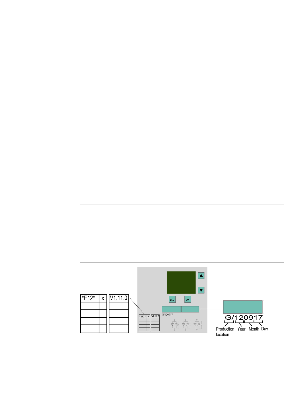
The PROFINET communication module only works with 3RW44 devices with product
version "E12" and firmware version V1.11.0 or higher.
For devices with product version E12 and firmware version 1.10.5, the PROFINET
communication module independently performs a firmware update to version 1.11 after
activation of the fieldbus interface.
PROFINET Communication Module for SIRIUS Soft Starter 3RW44
Manual, 12/2013, A5E31996495002A/RS-AA/001
17
Page 18

Product description
3.1
Fieldbus interfaces
3.1.1
PROFINET IO
Properties of PROFINET IO
3.1 Fieldbus interfaces
PROFINET IO is an open transmission system with real-time functionality defined in
accordance with the PROFINET standard. This standard defines a manufacturerindependent communication, automation and engineering model.
Accessories for wiring the PROFINET components are available in industrial quality.
● PROFINET discards the hierarchical PROFIBUS master/slave concept and deploys a
provider/consumer principle instead. The modules of an I/O device that will be subscribed
to by an IO controller are defined within the engineering phase.
● The quantity framework is extended in accordance with the options offered on
PROFINET IO. Parameter limits are not exceeded during configuration.
● The transmission rate is 100 Mbps.
● The configuration interface for users is generally the same as that on PROFIBUS DP (the
system is configured in STEP 7 > HW CONFIG).
● Integrated switch with 2 ports
● Supported Ethernet services: ping, arp, network diagnostics (SNMP)/MIB-2, LLDP
● Port diagnostics
● Device replacement without removable medium/programming device
● MRP (Media Redundancy Protocol)
● Supports PROFIenergy
● NTP (Network Time Protocol)
PROFINET Communication Module for SIRIUS Soft Starter 3RW44
18 Manual, 12/2013, A5E31996495002A/RS-AA/001
Page 19
Product description
Data transfer options
Communication between PC with Soft Starter ES 2007 + SP5 parameter assignment software (IO Supervisor) and
3RW44 via PROFINET
Communication between Soft Starter ES 2007 + SP5 PC parameter assignment software and 3RW44 via the local
Additional information
3.1 Fieldbus interfaces
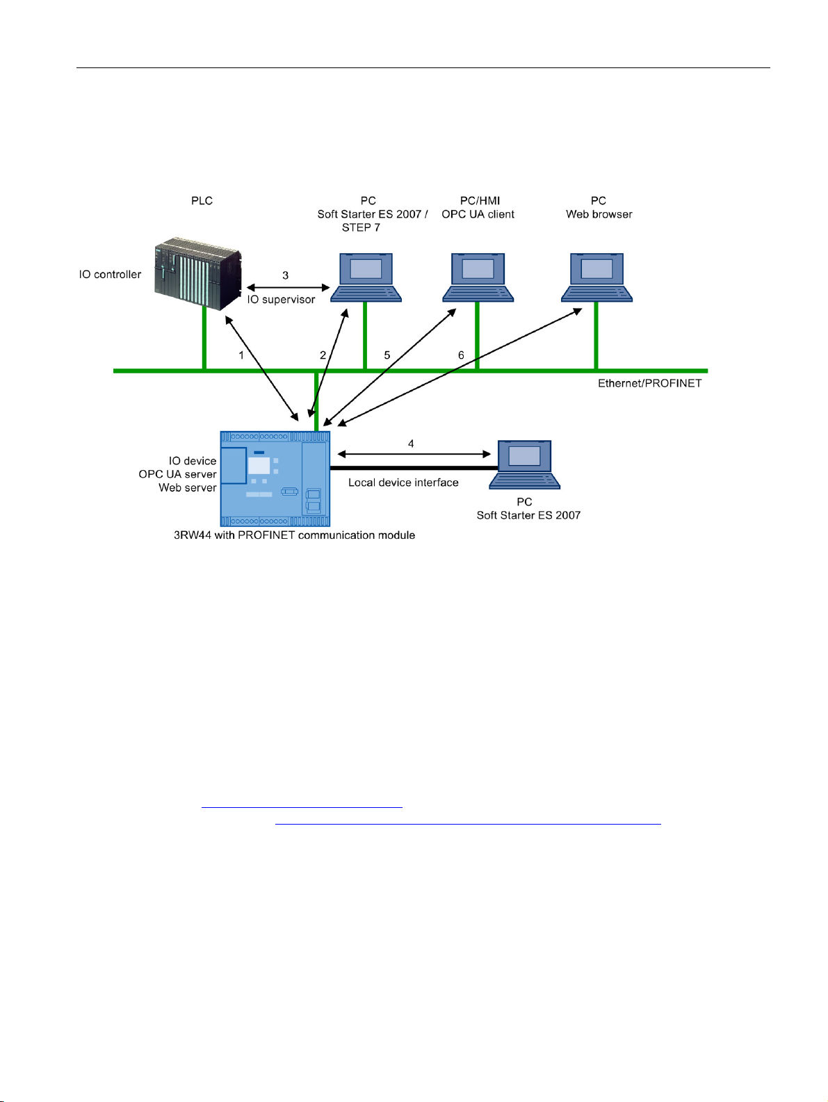
The following figure shows an overview of the communication functions supported by
SIRIUS 3RW44 soft starters, which are described in more detail in the following sections:
1 Communication between PLC (IO controller) and 3RW44 (IO device) via PROFINET / Ethernet
2
3 Communication between PC with Soft Starter ES 2007 + SP5 parameter assignment software and 3RW44 via
SIMATIC S7 (3RW44 integrated in STEP 7)
4
device interface (point-to-point via RS232 or USB)
5 Communication between PC or HMI with OPC UA client and 3RW44 via Ethernet/OPC UA
6 Communication between PC with web browser and 3RW44 via TCP/IP and HTTP/HTTPS (web server)
You can find additional information about PROFINET on the Internet
(http://www.siemens.com/profinet) and in system manual "SIMATIC PROFINET System
Description (http://support.automation.siemens.com/WW/view/de/19292127)".
PROFINET Communication Module for SIRIUS Soft Starter 3RW44
Manual, 12/2013, A5E31996495002A/RS-AA/001
19
Page 20
Product description
3.2
Communication principle
3.2 Communication principle
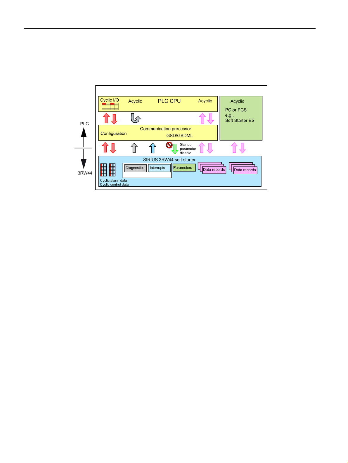
The following figure shows the communication principle, in which different data are
transferred depending on the operating mode:
PROFINET Communication Module for SIRIUS Soft Starter 3RW44
20 Manual, 12/2013, A5E31996495002A/RS-AA/001
Page 21
Product description
3.3
Display when PROFINET communication module is activated
3.3 Display when PROFINET communication module is activated
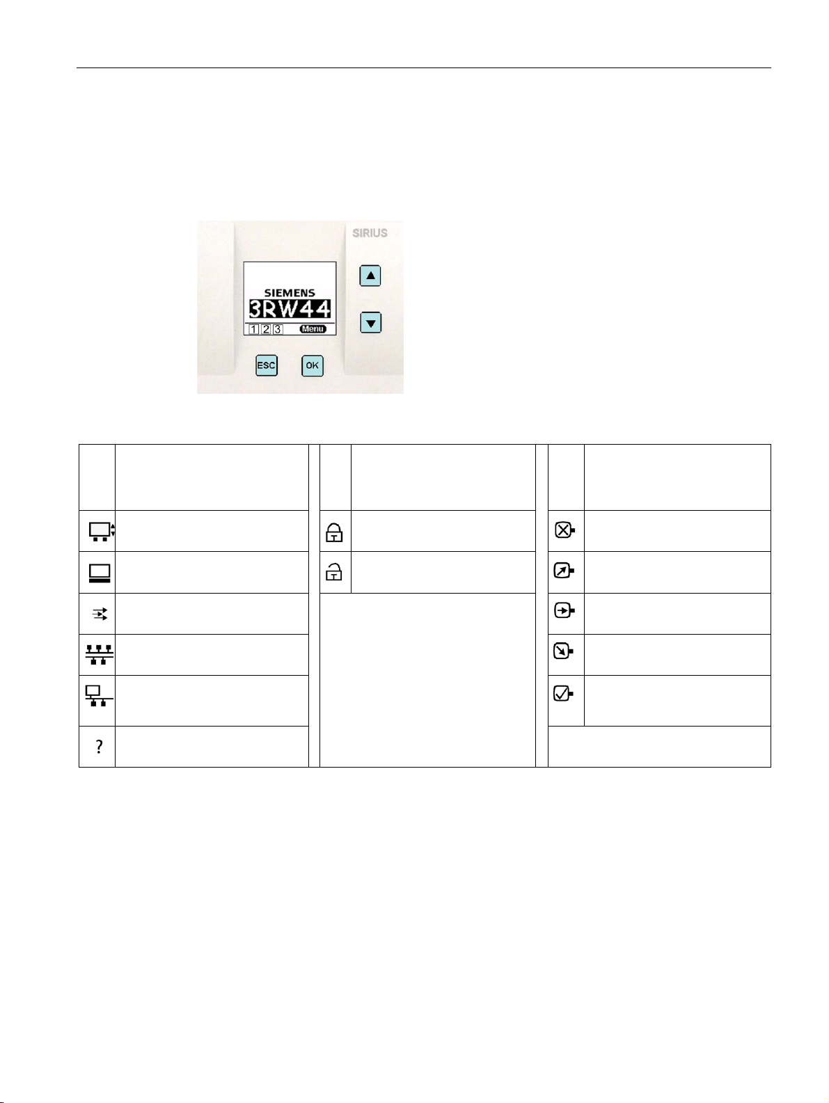
There is a graphic display on the front of the device from which the functions and states of
the 3RW44 can be read in plain text and with the help of symbols when control voltage is
applied.
1 Shows the operator panel that
currently has control priority and
is thus issuing the control
commands for the motor.
Display with keys
2 Indicates the user level setting 3 Indicates the current motor
status
Customer read only
No motor
Serial interface
Customer write
Control inputs
PLC via fieldbus (PROFIBUS,
PROFINET)
PC via bus (Soft Starter ES 2007
or web server or OPC UA
server)
No control device
Run-up
Motor is running
Coasting down
Motor ready to start
PROFINET Communication Module for SIRIUS Soft Starter 3RW44
Manual, 12/2013, A5E31996495002A/RS-AA/001
21
Page 22
Product description
3.4
Fieldbus for PROFINET menu structure
Additional menu commands when PROFINET communication module is activated
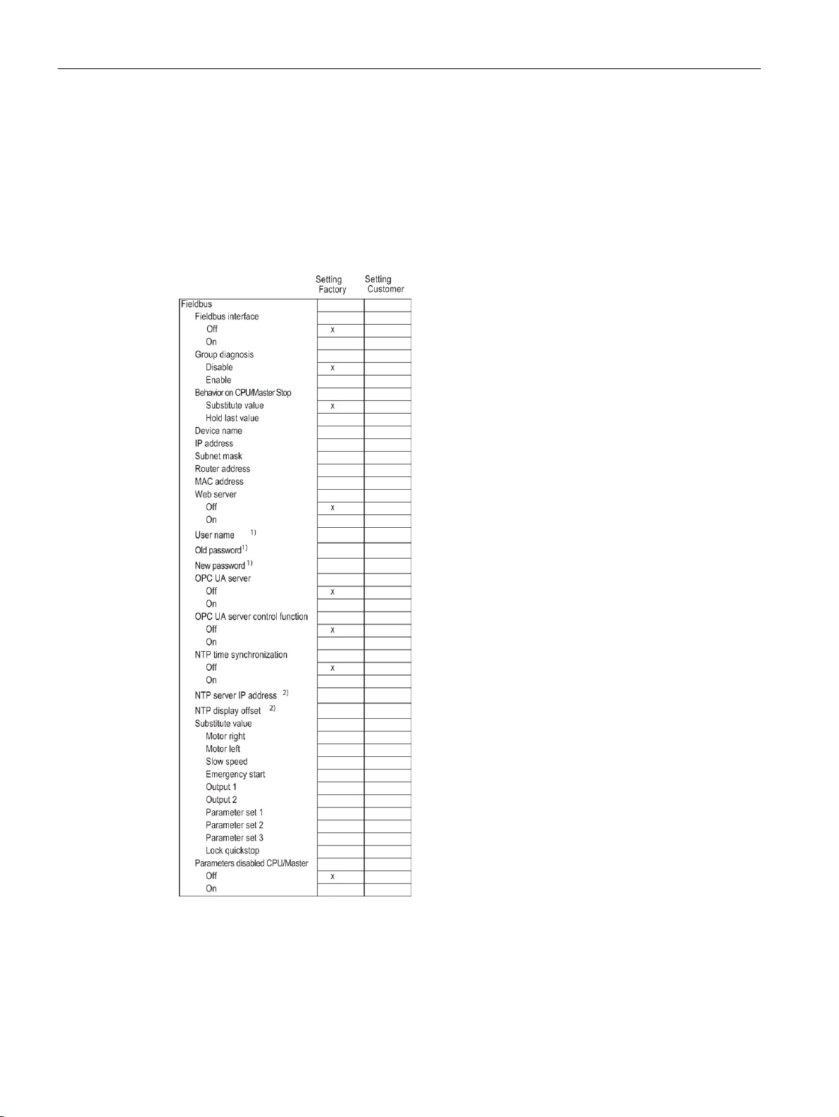
3.4 Fieldbus for PROFINET menu structure
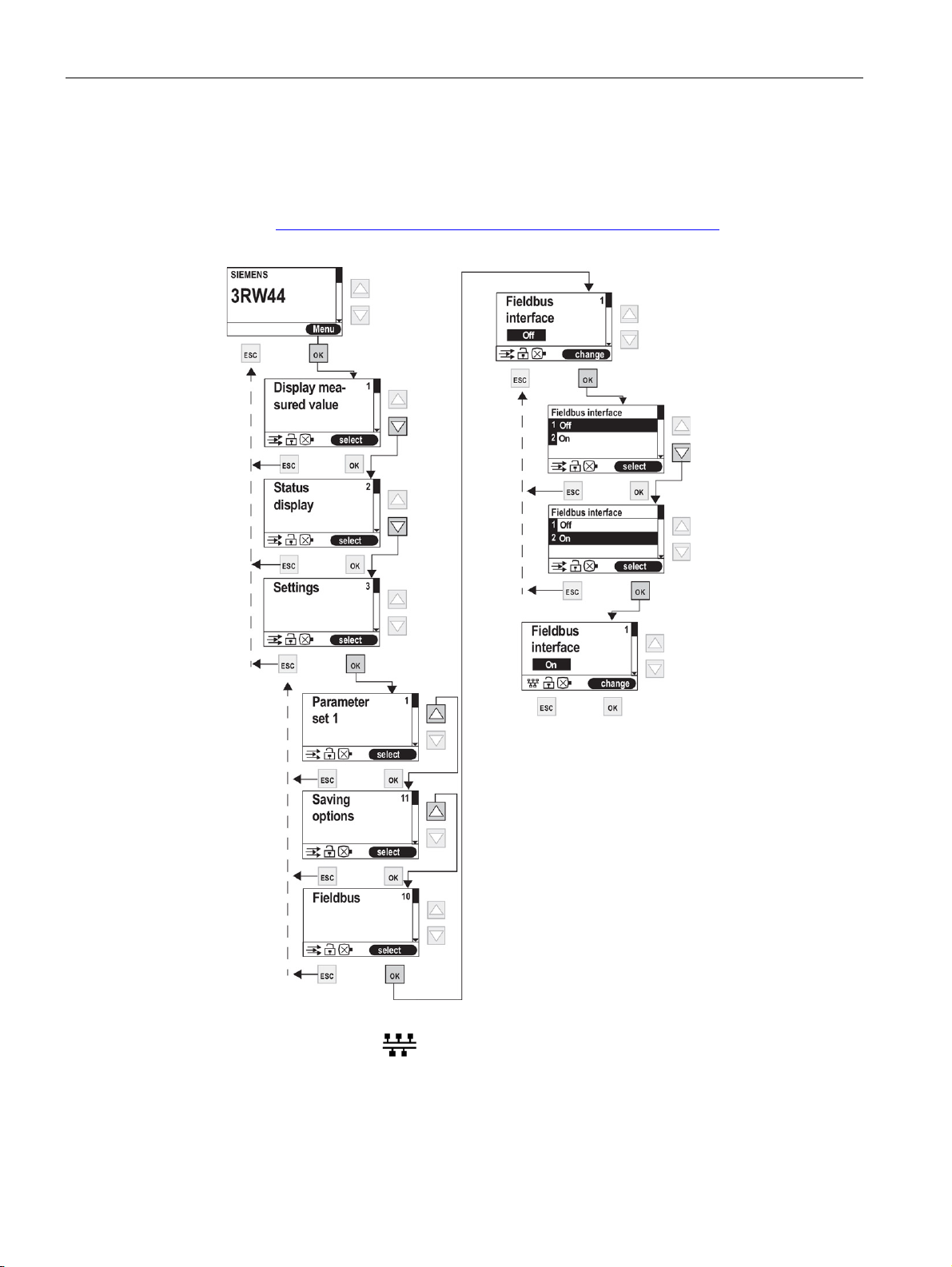
On the display of the 3RW44 soft starter, select "Settings > Fieldbus > Fieldbus interface >
On" to activate the PROFINET communication module. The following menu structure is
displayed:
1)
only if web server is activated
2)
only if NTP time synchronization is activated
PROFINET Communication Module for SIRIUS Soft Starter 3RW44
22 Manual, 12/2013, A5E31996495002A/RS-AA/001
Page 23
4
WARNING
Hazardous Voltage.
4.1
Inserting the PROFINET communication module
NOTICE
Danger of material damage.
Note
Note
Can Cause Death or Serious Injury. Turn off and lock out all power supplying this device
before working on this device.
Read the information in operating instructions "PROFINET Communication Module for Soft
Starter 3RW44", order no. 3ZX1012-0RW40-0NA1.
Before inserting the PROFINET communication module, disconnect the power to the
3RW44 soft starter.
The PROFINET communication module only works with 3RW44 devices with product
version "E12" and firmware version V1.11.0 or higher (see Product description (Page 17)).
For devices with product version E12 and firmware version 1.10.5, the PROFINET
communication module independently performs a firmware update to version 1.11 after
activation of the fieldbus interface.
PROFINET Communication Module for SIRIUS Soft Starter 3RW44
Manual, 12/2013, A5E31996495002A/RS-AA/001
23
Page 24
Installation / removal
Step
Description
Note
Combinations of PROFINET connecting cables
4.1 Inserting the PROFINET communication module
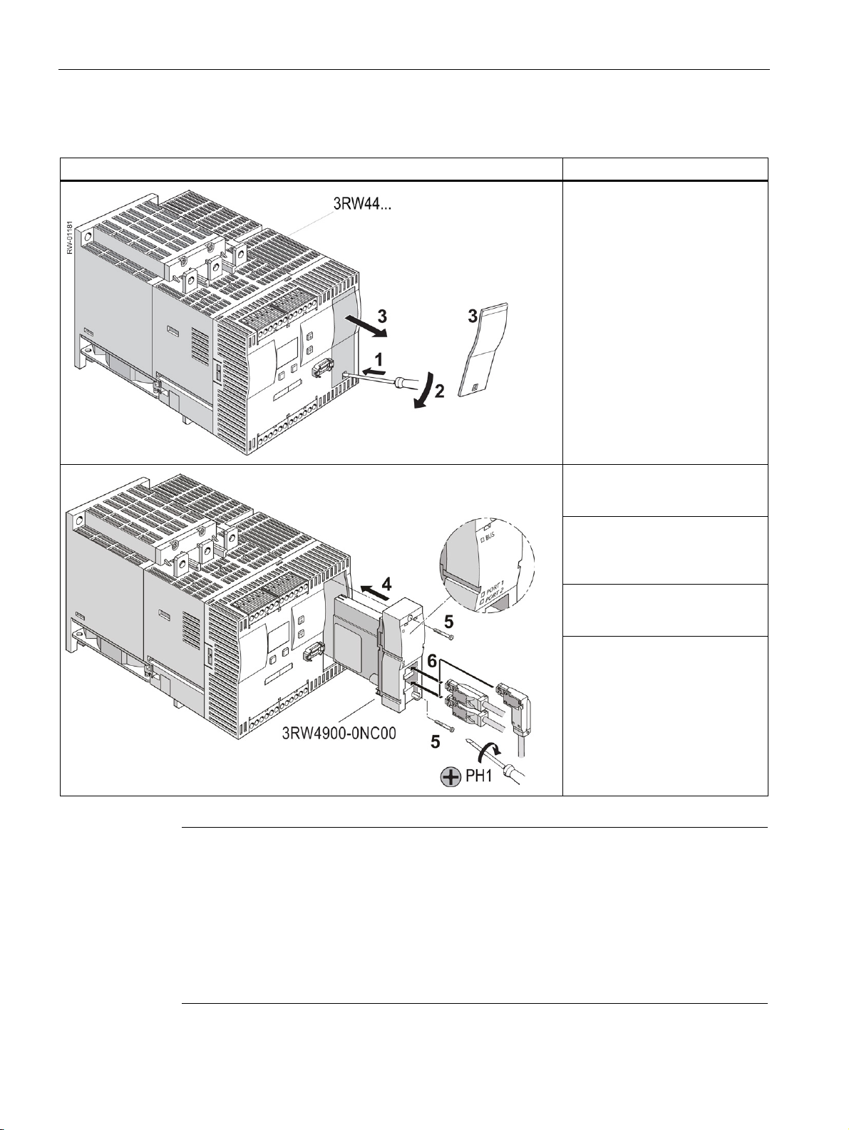
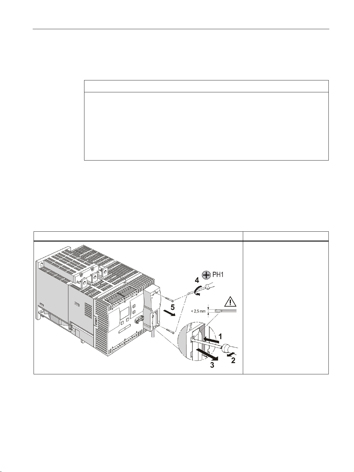
To install the PROFINET communication module, follow these steps:
Slide a small screwdriver into the
opening of the cover of the
3RW44 soft starter (1). Gently
press down with the screwdriver
(2) and remove the cover (3).
The following combinations of connector designs for PROFINET connecting cables are
possible:
• One straight connector
• Two straight connectors
• One angled connector
• One straight and one angled connector
Insert the PROFINET
communication module into the
device (4).
Fasten the PROFINET
communication module with the
enclosed screws (5). Torque 0.8
to 1.2 Nm (7 to 10.3 lb.in).
Insert the PROFINET connecting
cable into one of the sockets of
the communication module (6).
Switch on the supply voltage.
The "BUS" LED flashes yellow.
The communication module has
been inserted correctly, but has
not yet been activated (activation,
see section Commissioning
(Page 31)).
PROFINET Communication Module for SIRIUS Soft Starter 3RW44
24 Manual, 12/2013, A5E31996495002A/RS-AA/001
Page 25
Installation / removal
4.2
Ethernet cable to RJ45 socket
NOTICE
Ethernet connector
4.3
Removal of the PROFINET communication module
Step
Description
4.2 Ethernet cable to RJ45 socket
The Ethernet cable is connected to the basic unit.
Connect using only industrial Ethernet connectors, e.g.
• Siemens IE FC RJ45 PLUG 180 2x2, RJ45 connector (10/100MBIT/S) with robust metal
housing and Fast Connect connection method, for IE FC Cable 2x2 180° cable outlet,
order number 6GK1901-1BB10-2AA0 or
• Siemens IE FC RJ45 PLUG 90 2x2, RJ45 connector (10/100MBIT/S) with robust metal
housing and Fast Connect connection method, for IE FC Cable 2x2 90° cable outlet,
order number 6GK1901-1BB20-2AA0.
To remove the PROFINET communication module, follow these steps:
Slide a small screwdriver into the
opening of the PROFINET
communication module (1).
Gently press to the left with the
screwdriver (2) and withdraw the
PROFINET connecting cable (3).
Unscrew the screws on the
PROFINET communication
module (4) and withdraw the
communication module (5).
PROFINET Communication Module for SIRIUS Soft Starter 3RW44
Manual, 12/2013, A5E31996495002A/RS-AA/001
25
Page 26

Installation / removal
4.3 Removal of the PROFINET communication module
PROFINET Communication Module for SIRIUS Soft Starter 3RW44
26 Manual, 12/2013, A5E31996495002A/RS-AA/001
Page 27

5
5.1
Configuring soft starters
5.1.1
Configuring with a GSD file
General Station Description (GSD)
Configuring with a GSD file
5.1.2
Assigning parameters with the "Soft Starter ES 2007" software
Configuring refers to the configuring and the assigning of parameters of soft starters.
● Configuring: systematic arranging of individual soft starters (configuration).
● Assigning parameters: assigning parameters using the configuring software.
You can find additional information on parameters in the section "Data formats and data
records (Page 75)".
Refer to the glossary for the definition of the generic station description.
You configure the soft starter using the GSD file. The soft starter is integrated into your
system as an IO device by means of the GSD file.
You require a GSD file, which you can download from the Internet at:
PROFINET GSD files (http://support.automation.siemens.com/WW/view/de/38702563) >
PROFINET communication module
Following installation of the GSD file, you can find the SIRIUS Soft Starter 3RW44 PN in the
HW Catalog of STEP 7 V5 under "HW Catalog > PROFINET IO > Switching Devices > Motor
starter > Soft starter -> 3RW44". Insert your device variant into the PROFINET IO system.
You can find additional information on working with GSD files and on parameter assignment
of the PROFINET interface in the system manual SIMATIC PROFINET System Description
(http://support.automation.siemens.com/WW/view/de/19292127).
The "Soft Starter ES 2007 + SP5" software can be used to assign the SIRIUS 3RW44 soft
starter parameters via the device interface (point-to-point connection by means of the RS232
interface cable or USB interface cable).
"Soft Starter ES 2007" is the central software for commissioning, operation, and diagnostics
of SIRIUS 3RW44 soft starters.
PROFINET Communication Module for SIRIUS Soft Starter 3RW44
Manual, 12/2013, A5E31996495002A/RS-AA/001
27
Page 28

Configuring/assigning parameters
5.1.3
Diagnostics package
5.2
Configuring the properties of 3RW44 PN as IO device
Assigning the device name and IP parameters for an IO device
Assigning the device name using the configuration tool of the automation system
5.2 Configuring the properties of 3RW44 PN as IO device
There are two options for assigning parameters for the PROFINET communication module:
● Stand-alone program on PC or programming device with PROFINET connection (point-
to-point)
● Integration with the object manager (OM) in STEP 7
You can find detailed information about "Soft Starter ES" in the online help for the
program.
You can download the "Soft Starter ES 2007" software under Test version
(http://support.automation.siemens.com/WW/view/de/28323168). This is a free, 14-day test
version.
A free diagnostics package is available for the 3RW44 soft starters. It contains HMI
diagnostics masks for a touch panel. The diagnostics package is available in German and
English. You can download the diagnostics package
at (http://support.automation.siemens.com/WW/view/de/28557893).
PROFINET IO communication requires setting and configuring the IO device name and the
IP parameters.
The device name and the IP parameters can be assigned in different ways:
● Assigning the device name using the configuration tool of the automation system
● Configuring the device name using the "Soft Starter ES 2007" software and transferring it
to the device
● Assigning the device name via the display in the 3RW44 basic device
The device name is assigned during the commissioning phase by the configuration tool of
the automation system (e.g., STEP 7) and transferred to the IO device via Ethernet. For the
transfer, the soft starter must be connected and accessible via the Ethernet interface. The
device can be accessed via LAN using the MAC address (e.g., 00-0E-8C-BD-1F-27) printed
on the front of the communication module.
PROFINET Communication Module for SIRIUS Soft Starter 3RW44
28 Manual, 12/2013, A5E31996495002A/RS-AA/001
Page 29

Configuring/assigning parameters
Configuring the device name using the "Soft Starter ES 2007" software and transferring it to
the device
Note
Transferring the device parameters
Note
Changing the device name
Transferring IP parameters
5.2 Configuring the properties of 3RW44 PN as IO device
1. When the user performs the configuration, the device is given a technological name (e.g.:
Motor-1). STEP 7 automatically assigns an IP address. This requires that "Assign IP
address via IO controller" is activated.
2. The user assigns the device name to an IO device based on the MAC address and
transfers the name, for example, with the "Edit Ethernet Node" function".
3. The user downloads the configuration to the IO controller
4. The IO controller assigns the IP parameters based on the device name during startup.
In this case, the device name must be configured under "Device parameters > Field bus
interface > PROFINET Parameters > Station" and the "Overwrite device name in device"
parameter must be activated.
It is always possible to transfer the device parameters via the local device interface.
If the IP address has already been configured in a different way, the device parameters can
be transferred via PROFINET, too.
Any change of the device name using the "PROFINET Parameters" dialog box of "Soft
Starter ES 2007" requires a restart of the communication interface. A new start interrupts all
Ethernet and PROFINET links and reestablishes them afterward.
The IP parameters, consisting of IP address, subnet mask, and router can also be assigned
in various ways and transferred to the IO device.
PROFINET Communication Module for SIRIUS Soft Starter 3RW44
Manual, 12/2013, A5E31996495002A/RS-AA/001
29
Page 30

Configuring/assigning parameters
Note
Deleting IP parameters
Note
Transferring the device parameters
Note
Assigning the IP parameters
Note
Restarting the communication interface
Saving the parameters retentively
5.2 Configuring the properties of 3RW44 PN as IO device
Possibilities for this are:
● The IO controller assigns the IP parameters to the IO device.
IP parameters assigned by the IO controller are not stored retentively in the device, i.e.,
they are deleted when the supply voltage is switched off.
● The IP parameters are configured with the "Soft Starter ES 2007" software and
transferred to the device. In this case, the "Overwrite IP parameters in device" parameter
under "PROFINET Parameters > IP-Parameters" must be activated.
It is always possible to transfer the device parameters via the local device interface.
If the PROFINET IO device name or the IP address has already been configured in a
different way, the device parameters can also be transferred via PROFINET.
The IP parameters can be transferred to the selected device using the following functions
of the "Soft Starter ES 2007" software.
• Select "Target System > Edit Ethernet Node". This function is not identical to the
parameter assignment of the IP parameters using the "PROFINET Parameters" dialog
box.
• Select "PROFINET Parameters > IP-Parameters". The "Overwrite IP parameters in
device" parameter must be activated.
Any change of the IP parameters using the "PROFINET Parameters" dialog box of "Soft
Starter ES 2007" requires a restart of the communication interface.
A new start of the communication interface interrupts all Ethernet and PROFINET links
and reestablishes them afterward.
● Input of IP address, subnet mask, router address via the display of the 3RW44 (for
procedure, see Parameter settings in the soft starter under Fieldbus (Page 36)).
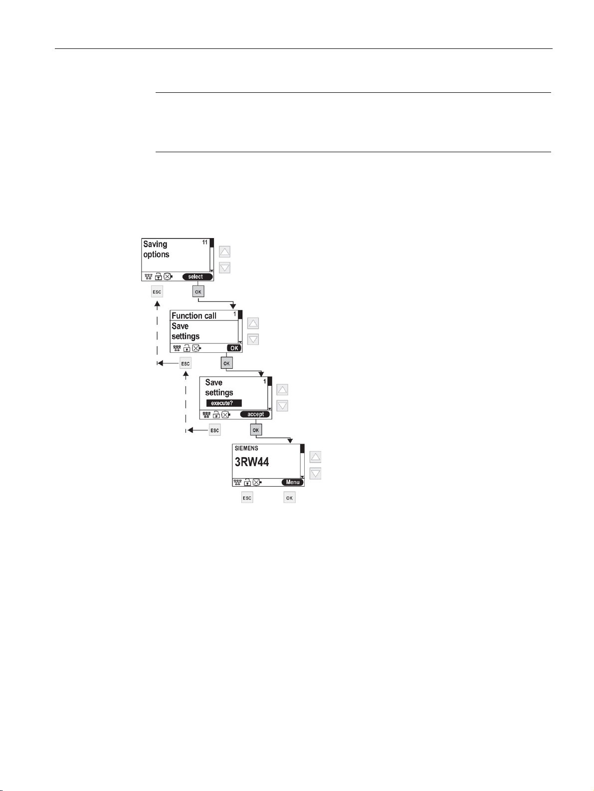
In order to save the modified parameters retentively, select "Save settings" in the menu of
the 3RW44 soft starter.
PROFINET Communication Module for SIRIUS Soft Starter 3RW44
30 Manual, 12/2013, A5E31996495002A/RS-AA/001
Page 31

6
6.1
Activation of the PROFINET communication module via the display
Note
Note
You can activate the PROFINET communication module ("Fieldbus" device function) via the
display on the 3RW44 soft starter.
The PROFINET communication module only works with 3RW44 devices with product
version "E12" and firmware version V1.11.0 or higher.
Following activation of the communication module, the default control priority automatically
switches from the inputs to "SPS über Feldbus PROFINET" (PLC via PROFINET fieldbus)
(automatic mode).
If an input with the "Manual operation local" function is active, the control priority does not
change.
PROFINET Communication Module for SIRIUS Soft Starter 3RW44
Manual, 12/2013, A5E31996495002A/RS-AA/001
31
Page 32
Commissioning
6.1.1
Activation of the fieldbus interface
6.1 Activation of the PROFINET communication module via the display
1. During first commissioning of the soft starter, you must run through the Quick Start menu.
See also the operating instructions "Soft Starter 3RW44", order no.: 3ZX1012-0RW440AA0 (http://support.automation.siemens.com/WW/view/de/21189750).
2. Press the designated button on the device.
3. The "BUS" LED flashes red.
4. If the fieldbus symbol
module has been successfully activated.
PROFINET Communication Module for SIRIUS Soft Starter 3RW44
32 Manual, 12/2013, A5E31996495002A/RS-AA/001
appears in the display, the PROFINET communication
Page 33
Commissioning
Note
6.1.2
Saving settings retentively
6.1 Activation of the PROFINET communication module via the display
If the "Parameters disabled CPU/Master" parameter is "Off" (basic factory setting), the
parameters set on the soft starter are overwritten with the values stored in the GSD file or
OM during bus startup. If this is not desired, the parameter must be set to "On".
In order to save the settings retentively, proceed as follows:
PROFINET Communication Module for SIRIUS Soft Starter 3RW44
Manual, 12/2013, A5E31996495002A/RS-AA/001
33
Page 34

Commissioning
6.2
Activation of the PROFINET communication module via software
Note
Note
6.2 Activation of the PROFINET communication module via software
You activate the PROFINET communication module ("Fieldbus" device function) using the
"Soft Starter ES 2007 + SP5" software.
The PROFINET communication module only works with 3RW44 devices with product
version "E12" and firmware version V1.11.0 or higher.
Following activation of the communication module, the default control priority automatically
switches from the inputs to "SPS über Feldbus PROFINET" (PLC via PROFINET fieldbus)
(automatic mode).
If an input with the "Manual operation local" function is active, the control priority does not
change.
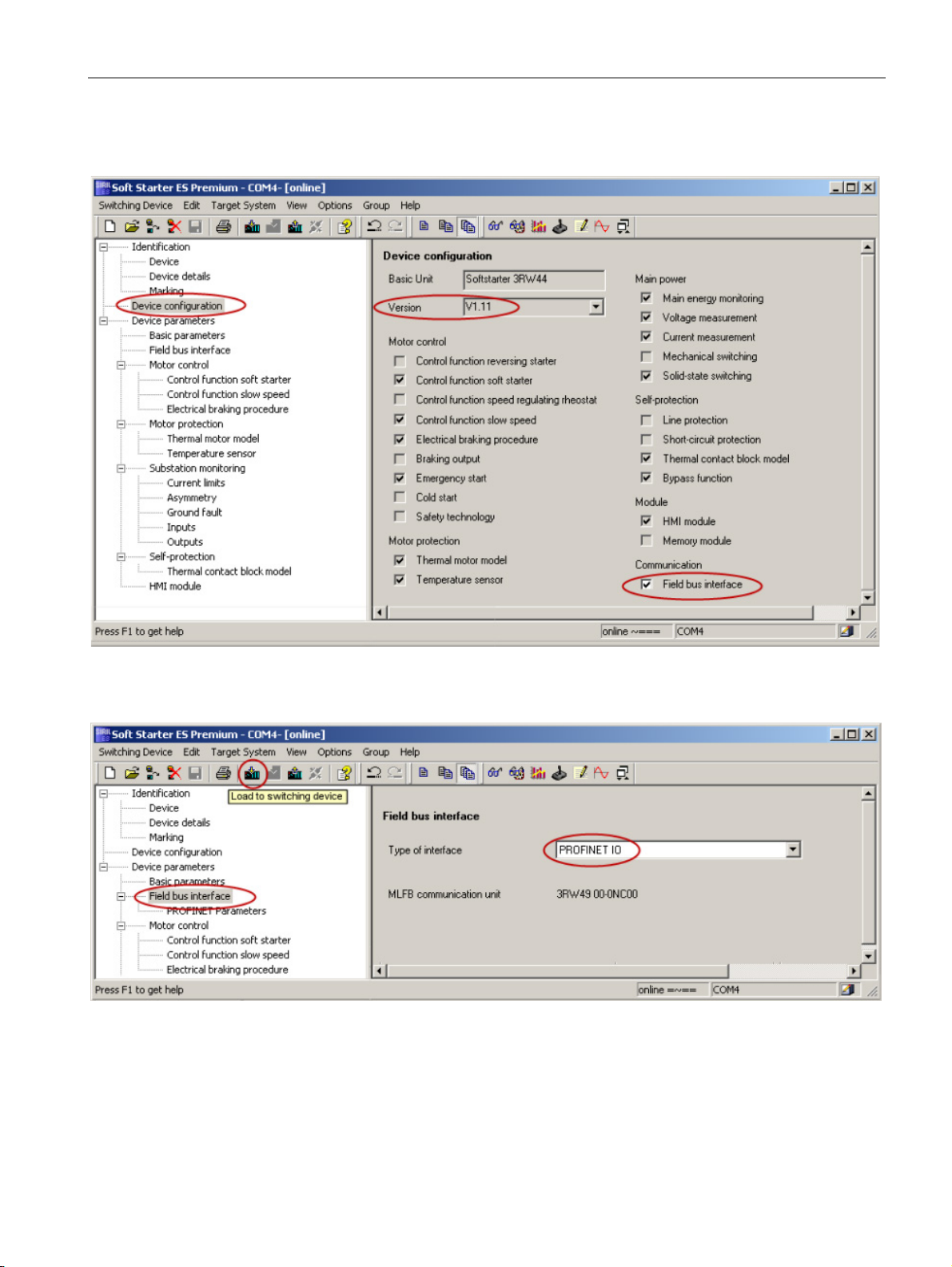
To activate the PROFINET communication module, follow these steps:
1. Connect the 3RW44 soft starter via the interface cable to a PC on which the "Soft Starter
ES 2007 + SP5" (or higher) software is installed.
2. Start the "Soft Starter ES 2007" software.
3. Select "Switching Device > Open Online" in the menu.
4. Select the "Local device interface" option in the "Open Online" dialog and select the
desired COM port under "Interface".
5. Click "OK".
6. Select "Device configuration" on the left side of the window.
7. Make sure that the firmware version of the connected 3RW44 soft starter is V1.11 or
higher.
PROFINET Communication Module for SIRIUS Soft Starter 3RW44
34 Manual, 12/2013, A5E31996495002A/RS-AA/001
Page 35
Commissioning
6.2 Activation of the PROFINET communication module via software
8. Select the "Field bus interface" check box on the right side of the window.
9. Select "Device parameters > Field bus interface" on the left side of the window.
10. On the right side of the window, select "PROFINET IO" as the Interface type.
11. You can set the parameters for communication under "Device parameters > Field bus
interface > PROFINET Parameters".
12. To transfer the changed parameters to the soft starter, select the "Load to Switching
Device" button in the toolbar or select "Target System > Load to Switching Device > All
Parameters" in the menu.
13. Acknowledge the changed PROFINET parameters with "OK".
PROFINET Communication Module for SIRIUS Soft Starter 3RW44
Manual, 12/2013, A5E31996495002A/RS-AA/001
35
Page 36

Commissioning
6.3
Parameter settings in the soft starter under Fieldbus
Group diagnosis
Behavior on CPU/Master Stop
Note
Device name
6.3 Parameter settings in the soft starter under Fieldbus
14. Acknowledge the activation of the PROFINET communication module with "OK": The
PROFINET communication module is activated.
15. If the BUS LED on the communication module flashes red and the fieldbus symbol
appears in the display, the communication module has been successfully activated.
You can use this parameter to specify whether diagnostics via the fieldbus interface is to be
enabled or disabled. If the group diagnostics parameter is set to "Disable", no error
messages is output.
1. Navigate in the menu of the 3RW44 to the "Fieldbus interface > On" menu command (see
Activation of the fieldbus interface (Page 32))
2. Use the arrow keys to navigate to "Group diagnosis".
3. Select "Disable" or "Enable".
You use this device parameter to specify how the soft starter is to react in the event of a
CPU/master stop:
● Hold last value
● Switch substitute value
This is only relevant in "Automatic" mode.
1. Navigate in the menu of the 3RW44 to the "Fieldbus interface > On" menu command (see
Activation of the fieldbus interface (Page 32))
2. Use the arrow keys to navigate to "Behavior on CPU/Master Stop".
3. Select "Substitute value" or "Hold last value".
1. Navigate in the menu of the 3RW44 to the "Fieldbus interface > On" menu command (see
Activation of the fieldbus interface (Page 32))
2. Use the arrow keys to navigate to "Device name".
3. Press "OK" to assign a device name.
4. You can use the arrow keys to assign letters or digits.
5. Pressing "OK" advances you to the next position in the device name.
PROFINET Communication Module for SIRIUS Soft Starter 3RW44
36 Manual, 12/2013, A5E31996495002A/RS-AA/001
Page 37

Commissioning
Note
Restrictions on name assignment
IP address
Subnet mask
6.3 Parameter settings in the soft starter under Fieldbus
6. Press the ESC key to accept the name.
7. Save the settings (see Saving settings retentively (Page 33)) and restart the device.
When the device name is entered by way of the menu, only names that conform to the
naming convention may be entered. For information on PROFINET naming conventions, see
PROFINET conventions (http://support.automation.siemens.com/WW/view/de/36062700).
The length of the device name is limited to 20 characters when the name is entered by way
of the menu.
1. Navigate in the menu of the 3RW44 to the "Fieldbus interface > On" menu command (see
Activation of the fieldbus interface (Page 32))
2. Use the arrow keys to navigate to "IP address".
3. Press "OK" to assign an IP address.
4. You can use the arrow keys to assign digits.
5. Click "OK" to confirm each position of the IP address and to advance to the next position.
6. When you have entered the desired IP address, press the "OK" key again to accept the
entered address.
7. Save the settings (see Saving settings retentively (Page 33)) and restart the device.
1. Navigate in the menu of the 3RW44 to the "Fieldbus interface > On" menu command (see
Activation of the fieldbus interface (Page 32))
2. Use the arrow keys to navigate to "Subnet mask".
3. Press "OK" to assign a name for the subnet mask.
4. You can use the arrow keys to assign digits.
5. Click "OK" to confirm each position and to advance to the next position.
6. When you have entered the desired subnet mask name, press the "OK" key again to
accept the entered name.
7. Save the settings (see Saving settings retentively (Page 33)) and restart the device.
PROFINET Communication Module for SIRIUS Soft Starter 3RW44
Manual, 12/2013, A5E31996495002A/RS-AA/001
37
Page 38

Commissioning
Router address
MAC address
Web server
6.3 Parameter settings in the soft starter under Fieldbus
If data must be forwarded via TCP/IP to a partner located outside the soft starter's own
network, this takes place via the router.
1. Navigate in the menu of the 3RW44 to the "Fieldbus interface > On" menu command (see
Activation of the fieldbus interface (Page 32))
2. Use the arrow keys to navigate to "Router address".
3. Press "OK" to assign a router address.
4. You can use the arrow keys to assign digits.
5. Click "OK" to confirm each position and to advance to the next position.
6. When you have entered the desired router address, press the "OK" key again to accept
the entered name.
7. Save the settings (see Saving settings retentively (Page 33)) and restart the device.
Each PROFINET device is assigned a unique device identification at the factory (MAC
address).
The MAC address can be read here and serves to uniquely identify the device.
1. Navigate in the menu of the 3RW44 to the "Fieldbus interface > On" menu command (see
Activation of the fieldbus interface (Page 32))
2. Use the arrow keys to navigate to "MAC address" in order to read it.
1. Navigate in the menu of the 3RW44 to the "Fieldbus interface > On" menu command (see
Activation of the fieldbus interface (Page 32))
2. Use the arrow keys to navigate to "Web server".
3. Select "On" or "Off".
4. Save the settings (see Saving settings retentively (Page 33)) and restart the device.
PROFINET Communication Module for SIRIUS Soft Starter 3RW44
38 Manual, 12/2013, A5E31996495002A/RS-AA/001
Page 39

Commissioning
User name
Old/new password
6.3 Parameter settings in the soft starter under Fieldbus
A user name is not assigned in the factory state.
You must assign a user name so that a password can be assigned later.
A user name and password is required for the web browser login in order to control the
device.
1. Navigate in the menu of the 3RW44 to the "Fieldbus interface > On" menu command (see
Activation of the fieldbus interface (Page 32))
2. Use the arrow keys to navigate to "User name".
3. Press "OK" to edit the user name.
4. You can use the arrow keys to enter a user name.
5. Click "OK" to confirm each position and to advance to the next position.
6. When you have entered the desired user name, press the "OK" key again to accept the
entered name.
A password is not assigned in the factory state.
You must assign a user name in order to assign a password.
A user name and password is required for the web browser login in order to control the
device.
1. Navigate in the menu of the 3RW44 to the "Fieldbus interface > On" menu command (see
Activation of the fieldbus interface (Page 32))
2. Use the arrow keys to navigate to "Old/new password".
3. Press "OK" to edit the password.
4. You can use the arrow keys to enter a password.
5. Click "OK" to confirm each position and to advance to the next position.
6. When you have entered the desired password, press the "OK" key again to accept the
entered password.
7. For the password change, the old password also has to be entered in order for the new
one to be accepted. This step can be skipped if an old password does not exist (e.g., in
the factory state or when a password is deleted).
During entry, the password (both the old and new passwords) is displayed in plain text.
This allows you to check it before saving.
When the password is entered via the "Soft Starter ES" software, only "*" is displayed.
The new password must be entered here twice for confirmation.
PROFINET Communication Module for SIRIUS Soft Starter 3RW44
Manual, 12/2013, A5E31996495002A/RS-AA/001
39
Page 40

Commissioning
OPC UA server
OPC UA server control function
NTP time synchronization
NTP server IP address
6.3 Parameter settings in the soft starter under Fieldbus
1. Navigate in the menu of the 3RW44 to the "Fieldbus interface > On" menu command (see
Activation of the fieldbus interface (Page 32))
2. Use the arrow keys to navigate to "OPC UA server".
3. Select "On" or "Off".
4. Save the settings (see Saving settings retentively (Page 33)) and restart the device.
1. Navigate in the menu of the 3RW44 to the "Fieldbus interface > On" menu command (see
Activation of the fieldbus interface (Page 32))
2. Use the arrow keys to navigate to "OPC UA server control function".
3. Select "On" or "Off".
4. Save the settings (see Saving settings retentively (Page 33)) and restart the device.
1. Navigate in the menu of the 3RW44 to the "Fieldbus interface > On" menu command (see
Activation of the fieldbus interface (Page 32))
2. Use the arrow keys to navigate to "NTP time synchronization".
3. Select "On" or "Off".
4. Save the settings (see Saving settings retentively (Page 33)).
1. Navigate in the menu of the 3RW44 to the "Fieldbus interface > On" menu command (see
Activation of the fieldbus interface (Page 32))
2. Use the arrow keys to navigate to "NTP server IP address".
3. Press "OK" to assign an IP address.
4. You can use the arrow keys to assign digits.
5. Click "OK" to confirm each position of the IP address and to advance to the next position.
6. When you have entered the desired IP address, press the "OK" key again to accept the
entered address.
PROFINET Communication Module for SIRIUS Soft Starter 3RW44
40 Manual, 12/2013, A5E31996495002A/RS-AA/001
Page 41

Commissioning
NTP display offset
Substitute value
Parameters disabled CPU/Master
Note
6.3 Parameter settings in the soft starter under Fieldbus
The offset of the NTP display is the time difference between the actual local time and the
UTC time (UTC = Universal Time Coordinated) in minutes.
This can be used to indicate the actual local time. A value from -1440 min (-1 day) to 1440
min (+1 day) can be entered.
In the event of a bus failure, the outputs of the soft starters are controlled by a corresponding
substitute process image.
1. Navigate in the menu of the 3RW44 to the "Fieldbus interface > On" menu command (see
Activation of the fieldbus interface (Page 32))
2. Use the arrow keys to navigate to "Parameters disabled CPU/Master".
3. Press "OK".
4. Select "On" or "Off".
If the "Parameters disabled CPU/Master" parameter is "Off" (basic factory setting), the
parameters set on the soft starter are overwritten with the values stored in the GSD file or
OM during bus startup. If this is not desired, the parameter must be set to "On".
5. Confirm the selection with the "OK" key.
PROFINET Communication Module for SIRIUS Soft Starter 3RW44
Manual, 12/2013, A5E31996495002A/RS-AA/001
41
Page 42

Commissioning
6.3 Parameter settings in the soft starter under Fieldbus
PROFINET Communication Module for SIRIUS Soft Starter 3RW44
42 Manual, 12/2013, A5E31996495002A/RS-AA/001
Page 43

7
7.1
PROFIenergy
Supported commands
Command
Command ID
Meaning
PROFIenergy, a profile defined by the PROFINET user organization, lays the foundations for
a vendor-neutral, universal system for flexible, short-term, and intelligent shutdown of
individual consumers or whole production units.
PROFIenergy (PE) supports the following two functions:
● PE_Energy_Saving_Function
Supports targeted shutdown of consumers during idle times.
● PE_Measured_Value_Function
The PE_Measured_Value_Function supplies the measured values required for optimizing
energy consumption.
The 3RW44 soft starter with PROFINET, together with the PROFIenergy data record
index 0x80A0, supports the "PE_Energy_Saving_Function" and the
"PE_Measured_Value_Function" for the motor current. These are designated as commands,
since they trigger reactions in the soft starter.
In addition, the 3RW44 soft starter with PROFINET supplies additional service commands
that provide information about the status of the soft starter, as defined in PROFIenergy.
These can then be evaluated and further processed in the user program.
Start_Pause 0x01 The soft starter switches to energy saving mode.
End_Pause 0x02 The soft starter switches back to the operating
Query_Modes
- list_energy_saving_modes
- get_mode
PEM_Status 0x04 Provides the status of the current PE mode.
PE_Identify 0x05 Provides a list of supported PROFIenergy
Query_Measurement
- get_measurement_list
- get_measurement_values
mode.
0x03 Energy saving mode
- Provides a list of supported energy saving
modes.
- Provides the parameter values that the
PE_Energy_Saving_Function works with.
commands/functions.
0x10 Measured values
- Provides a list of supported PE_measured
values.
- Delivers the supported PE_measured values.
PROFINET Communication Module for SIRIUS Soft Starter 3RW44
Manual, 12/2013, A5E31996495002A/RS-AA/001
43
Page 44

Functions
7.1.1
Energy saving function command
Command "PE_Energy_Saving_Function"
Note
7.1 PROFIenergy
The 3RW44 soft starter distinguishes between two different data transmission modes:
PE_Mode_ID = 255 Ready to operate
PE_Mode_ID = 01 Energy saving mode
t
Time_to_Pause Time the soft starter requires in order to change to energy
off
saving mode. For the 3RW44 soft starter, this time is 200 ms.
An assigned ramp-down time is added to this (if available and
if the starter was in the ON state):
= 200 ms + ramp-down time
t
off
If the soft starter was already off before the pause, energy
saving mode will be switched to after only 200 ms.
Time_min_length_of_stay Minimum time that the device spends or should spend in
t
off_min
energy saving mode.
For 3RW44: 0 ms
Time_to_operate Time that will elapse before the starter changes back to the
t
on
operating state. Since the process image is evaluated again
immediately when the 3RW44 exits energy saving mode, this
time is 0 ms.
t
Pause_min
Time_min_Pause Time that is compared with t
the "Start_Pause" command to the soft starter); if t
t
, the device switches to energy saving mode.
Pause_min
(is transferred together with
Pause
Paus e
≥
A pending fault is not acknowledged by the switchover to energy saving mode, i.e., the
pending fault is saved internally and can be read. When energy saving mode is exited, the
fault must be eliminated and acknowledged.
PROFINET Communication Module for SIRIUS Soft Starter 3RW44
44 Manual, 12/2013, A5E31996495002A/RS-AA/001
Page 45

Functions
Reaction of the starter when the energy-saving function is activated:
Interactions with the various operating modes
Requirements for switchover of the starter to energy saving mode
7.1 PROFIenergy
Shutdown of the motor by suppressing (masking) of the PIO bits Motor right, Motor left,
Brake. The other PIO bits (e.g., Trip Reset) remain active.
● PE is operative only in Automatic mode.
● Manual mode is not influenced by PE; it is also possible to switch to manual mode and
thereby to control the motor manually.
● Both cyclic and acyclic data transmission (PII, data records, diagnostics, interrupts, etc.)
to and from the soft starter are still possible.
The switchover to the "Pause" energy saving mode only takes effect when the transmitted
pause time (t
a switchover is only performed when the pause is longer than the time required by the soft
starter to switch off the main energy for the motor.
) is greater than the device-specific minimum pause time. This means that
Pause
An assigned ramp-down time must be added to the device-specific minimum pause time.
Each switchover to energy saving mode is recorded in the "Events" log list.
Entry: "Energy saving mode active"
PROFINET Communication Module for SIRIUS Soft Starter 3RW44
Manual, 12/2013, A5E31996495002A/RS-AA/001
45
Page 46

Functions
7.1.2
Measured value function command
Command "PE_Measured_Value_Function"
7.1.3
Function blocks for SIMATIC S7
7.1 PROFIenergy
Measured values for energy need to be supplied for efficient energy management.
The PROFIenergy specification offers various measured values from which to choose, each
of which is assigned a measured value ID. The 3RW44 supports the measured values
"Instantaneous values of the phase current" and "Mean value of the three phase currents".
The measured values are uniquely identified by IDs. Measured value IDs 7, 8, 9, and 33 are
supported:
● ID = 7: Instantaneous value of the phase current a (L1)
● ID = 8: Instantaneous value of the phase current b (L2)
● ID = 9: Instantaneous value of the phase current c (L3)
● ID = 33: Mean value of the three phase currents (a+b+c) / 3
The current values are transferred with the following tolerances:
● Accuracy Domain (unsigned8) = 0x01 → percent of full-scale reading
● Accuracy Class (unsigned8) = 0x11 → 3%
● Range (Float32) = I
The result is that the measured values are transferred with an accuracy of 3% relative to the
maximum configurable rated operating current I
The application description "Saving Energy with SIMATIC S7 and ET 200S"
(http://support.automation.siemens.com/WW/view/en/41986454) is available on the Internet
Service Portal of Siemens AG. It also contains an example program for use of the
PROFIenergy functions. You can also make use of the blocks from the example to
implement PROFIenergy functions in conjunction with the 3RW44 soft starter with
PROFINET.
In the section "Functionality FB 815 PE_START_END" of the application description, you can
find the description of the block that can be used to directly transfer the "PE_START_Pause"
and "PE_END_Pause" commands to an IO device.
You can use the FB 815 "PE_START_END" function block to transfer the "START_Pause"
and "END_Pause" commands directly to 3RW44 PN.
For use of other functions, in the section "Functionality FB 816 PE_CMD" you can find a
universal function block that you can use to transfer other commands of the PROFIenergy
profile (e.g. Query_Modes, PEM_Status, PE_Identify, Query_Measurement).
(fixed value parameter)
e_max
.
e
You can also find the structure of the command and response data of the FB 816 in the
section "Response Data" of application description "Saving Energy with SIMATIC S7 and
ET 200S."
PROFINET Communication Module for SIRIUS Soft Starter 3RW44
46 Manual, 12/2013, A5E31996495002A/RS-AA/001
Page 47
Functions
7.2
OPC UA server
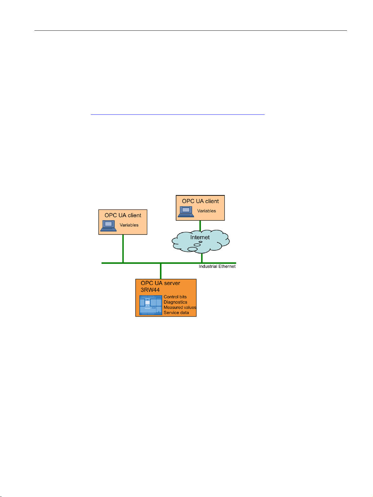
Background information on OPC UA
7.2.1
Features of OPC UA
7.2 OPC UA server
You can find background information on OPC UA in the application description
"Programming an OPC UA .NET Client with C# for the SIMATIC NET OPC UA Server"
(http://support.automation.siemens.com/WW/view/de/42014088).
OPC UA offers the following features:
● Use of open and non-platform-specific protocols for network communication.
● Internet access and communication through firewalls.
● Integrated access control and security mechanisms at the protocol and application level.
PROFINET Communication Module for SIRIUS Soft Starter 3RW44
Manual, 12/2013, A5E31996495002A/RS-AA/001
47
Page 48

Functions
7.2.2
Reading and writing data
Writing data
Reading data
from
7.2.3
Activating the OPC UA server
Activating the OPC UA server via the display
Note
Restarting the communication interface
Activating the OPC UA server via the"Soft Starter ES 2007" software
7.2 OPC UA server
Writing data means that data are transmitted to the soft starter.
Reading data means that data are transmitted
In the default setting, the OPC UA server and the OPC UA server control function are not
active.
To activate the OPC UA server via the display of the 3RW44, follow these steps:
1. Select "Settings > Fieldbus > OPC UA server > On" in the menu. Objects can now be
read.
2. To enable execution of control functions, select "Einstellungen > Feldbus > OPC-UAServer Steuerfunktionen > Ein" (Settings > Field bus > OPC UA Server control function >
On) in the menu and save the settings (see Parameter settings in the soft starter under
Fieldbus (Page 36)).
Each change to the "OPC UA Server" parameter requires that the communication interface
be restarted.
the soft starter.
A restart of the communication interface disconnects and then reconnects all Ethernet and
PROFINET connections.
The OPC UA server can also be activated via the "Soft Starter ES 2007" software. For safety
reasons the software must be connected via the local device interface.
1. Select "Device parameters > Field bus interface > PROFINET Parameters" in the menu.
2. In the "PROFINET Parameters" window, choose "OPC UA Server / OPC UA Server
control function".
PROFINET Communication Module for SIRIUS Soft Starter 3RW44
48 Manual, 12/2013, A5E31996495002A/RS-AA/001
Page 49

Functions
Note
Activation of the "OPC UA Server" function
Note
Activation of the "OPC UA Server control function" function
Note
Restarting the communication interface
7.2.4
Setting the IP parameters
7.2 OPC UA server
You only have access to read-only variables.
The "OPC UA Server" function must be activated. In addition, you have write-access to
variables.
Activate this function only if you want to control the 3RW44 via the OPC UA Server. Ensure
that the connection between the server and client is protected from unauthorized access.
Use security policy "Basic128Rsa15" and message security mode "SignAndEncrypt".
Each change to the "OPC-UA Server aktivieren" (Activate OPC UA Server) parameter
requires a restart of the communication interface.
A restart of the communication interface disconnects and then reconnects all Ethernet and
PROFINET connections.
To enable a connection to be established via OPC UA, the 3RW44 soft starter must have
valid IP parameters.
Example of the URL of the OPC UA server in the 3RW44 PROFINET:
opc.tcp://192.168.0.2:4840, where 192.168.0.2 is the IP address of 3RW44.
The IP parameters, consisting of the IP address, Subnet mask, and Router, can be
configured with the "Soft Starter ES 2007" software or via the display of 3RW44 and
transferred to the device.
You can overwrite the existing IP parameters in the device using the "Soft Starter ES 2007"
software if the "Overwrite IP parameters in device" parameter is activated.
PROFINET Communication Module for SIRIUS Soft Starter 3RW44
Manual, 12/2013, A5E31996495002A/RS-AA/001
49
Page 50
Functions
7.2.5
Access to the OPC UA server
7.2 OPC UA server
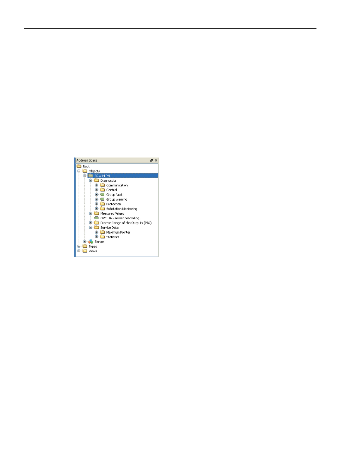
The OPC UA server integrated in SIRIUS 3RW44 soft starter PROFINET makes available
the following structured objects in its address space. The client has read access and, in
some cases, write access to these objects.
The following requirements must be met for write access:
● A secured connection with security policy "Basic128Rsa15" and message security mode
"SignAndEncrypt" and
● "OPC UA Server control function" check box is selected
The representation of the OPC UA variables depends on the OPC UA client used. Below you
can see an example representation of the variable structure:
You can find a detailed description of the individual variables in section OPC UA variables
(Page 104).
PROFINET Communication Module for SIRIUS Soft Starter 3RW44
50 Manual, 12/2013, A5E31996495002A/RS-AA/001
Page 51

Functions
Read/Write
Additional specifications for OPC UA server
Note
Note
7.2 OPC UA server
Write accesses in the "Process image of the outputs (PIO)" are limited to one OPC UA client:
only the client that sets the "OPC UA - server controlling" tag
(node ID 270) to 1 without error assumes the control priority and thus write access.
If the value of the "OPC UA server controlling" tag is set to 0, the control priority and thus
write access is given up.
Write access is only possible via a secure connection. The "OPC UA Server control function"
function must be activated for this.
● Variable (Read) - for reading the current state of the process image
● Variable (Write) - for controlling the soft starter using OPC UA variables
Maximum number of clients 2
Maximum number of subscriptions (subscribable variables) 20
Shortest update interval for subscriptions 200 ms
When data are being transferred via OPC UA and a web page is called simultaneously by
the web server, the transmission time via OPC UA may be prolonged considerably.
OPC-UA client functionality depends on the manufacturer. The occurrence of connection
failures in individual OPC UA clients cannot be excluded.
Simultaneous use of OPC UA servers and web servers is not recommended.
PROFINET Communication Module for SIRIUS Soft Starter 3RW44
Manual, 12/2013, A5E31996495002A/RS-AA/001
51
Page 52
Functions
7.2.6
Establishing a connection to the OPC UA server
Note
Configuring the connection on the client side
Supported OPC UA services of the OPC UA server in 3RW44 PN
Explanation of security settings:
Security Policy
MessageSecurityMode
7.2 OPC UA server
An OPC UA client can access process values in the hierarchical namespace of the OPC UA
server.
To enable this, the OPC UA server and the OPC UA client authorize each other by
exchanging certificates. You can additionally encrypt the data traffic.
The OPC UA server classifies every certificate of an OPC UA client as "trustworthy" by
default.
You can obtain information directly from the manufacturer of the software that is to access
the data of the OPC UA server in the 3RW44 PN via OPC UA.
3RW44 PN supports the following OPC UA services:
● SecurityPolicy:
– None
– Basic128Rsa15
● MessageSecurityMode:
– None
– Sign&Encrypt.
The following table shows the security functions supported by the OPC UA server, which
have to be set in the connection configuration of the OPC UA client:
None 1) None
Basic128Rsa152 2) SignAndEncrypt 3)
1) Exchange of certificates is deactivated
2) The data packets are exchanged unsecured between the client and server after the
certificate has been verified
3) The data packets are signed and encrypted with the certificates.
PROFINET Communication Module for SIRIUS Soft Starter 3RW44
52 Manual, 12/2013, A5E31996495002A/RS-AA/001
Page 53
Functions
WARNING
Unsecured connection between the client and the server possible!
Note
Requirement for certificate exchange in 3RW44 PN
7.2.7
Connection monitoring
7.2 OPC UA server
Use the setting "none" for test purposes only.
During productive operation, use at least the following settings for secure communication
between the client and server:
- Security Policy: Basic128Rsa15
- Message Security Mode: Sign.
The certificate exchange requires the presence of a valid time.
Time synchronization in the device is not required for certificate exchange since the time is
already set during production.
Please note the validity period of the certificates and update the time of your PC, if
necessary.
The PC time must be within the validity period of the certificate.
If the OPC UA connection is disconnected, all OPC UA control variables in the SIRIUS
3RW44 soft starter are deleted. A disconnection is detected after approximately 10 seconds.
No fault is triggered in the 3RW44 soft starter.
PROFINET Communication Module for SIRIUS Soft Starter 3RW44
Manual, 12/2013, A5E31996495002A/RS-AA/001
53
Page 54

Functions
7.3
Web server
7.3.1
Contents of web pages
Note
Number of web server connections:
7.3.2
Activating the web server
Note
Restarting the communication interface
7.3 Web server
Together with the web server, the PROFINET communication module allows you to call up
information of the 3RW44 soft starter from a programming device or PC using an HTTP
client.
The following web pages are available:
● Identification I&M0 (Slot 0), I&M0...3 (Slot 1)
● Diagnostics
– Control system
– Protection
– Plant monitoring
– Communication
● Measured values
● Service data
– Statistics
– Maximum pointer (cannot be reset)
● Log list (cannot be deleted)
● Control
Up to 5 connections are supported.
The default setting of the web server is "not active."
Each change to the configuration of the web server requires that the communication
interface be restarted.
A new start of the communication interface interrupts all Ethernet and PROFINET links and
reestablishes them afterward.
PROFINET Communication Module for SIRIUS Soft Starter 3RW44
54 Manual, 12/2013, A5E31996495002A/RS-AA/001
Page 55

Functions
Activating the web server via the display
Activating the web server via the "Soft Starter ES 2007" software
7.3.3
Setting the IP parameters
Setting the IP parameters via the display
Setting the IP parameters via the software
Note
Retaining the IP address of the web server
7.3 Web server
The web server can be activated via the display of the 3RW44 soft starter.
1. Select "Einstellungen > Feldbus > Webserver > Ein" (Settings > Field bus > Web server >
On) in the menu.
2. Save the settings (see Parameter settings in the soft starter under Fieldbus (Page 36))
and restart the device. The web pages can now be accessed.
The web server can be activated via the "Soft Starter ES 2007" software. For safety reasons
the software must be connected via the local device interface.
1. Select "Device parameters > Field bus interface > PROFINET Parameters" in the menu.
2. In the "PROFINET Parameters" window, select the "Webserver" check box.
3RW44 PN must have valid IP parameters in order for a connection to be established via the
web.
The IP parameters, consisting of the IP address, Subnet mask, and Router, can be
configured using the display of 3RW44 or with the "Soft Starter ES 2007" software and
transferred to the device.
To set the IP parameters via the display of 3RW44, select "Einstellungen > Feldbus > IPAdresse / Subnetzmaske / Router Adresse" (Settings > Field bus > IP address / Subnet
mask / Router address" (see Parameter settings in the soft starter under Fieldbus
(Page 36)).
To set the IP parameters via the "Soft Starter ES 2007" software, select "Device parameters
> Field bus interface > PROFINET Parameters".
You can overwrite the existing IP parameters in the device using the "Soft Starter ES 2007"
software if the "Overwrite IP parameters in device" parameter is activated.
In order to retain the same IP address of the web server, we recommend that you not use IO
controller to assign the IP address.
PROFINET Communication Module for SIRIUS Soft Starter 3RW44
Manual, 12/2013, A5E31996495002A/RS-AA/001
55
Page 56

Functions
7.3.4
Access to the web server
Web browser
Settings of the web browser for access to the information
7.3.5
Establishing a connection to the web server
Logon to the web server
Note
Control via the web server
Logon
7.3 Web server
For access to web pages in the 3RW44 PN, you need a web browser.
The following web browsers are suitable for communication with 3RW44:
● Internet Explorer (recommended version as from 8.0)
● Firefox (recommended version as from 3.6)
Check the following settings, which are a precondition for access to the information made
available via the web:
● To load diagnostics data, JavaScript must be activated in the web browser.
● The web browser must support frames.
● Cookies must be permitted.
● The web browser should be configured in such a way that whenever it accesses a page,
it automatically downloads the current data from the server.
If you are using a firewall in your programming device or PC, the following port must be
enabled for use of the web diagnostics. "http Port 80/TCP" or, in the case of secure
connections, "https Port 443/TCP."
You can only use functions for controlling the soft starter after you have logged on to the web
server with user name and password. Only then are the buttons with a controlling function
active.
If the soft starter is being controlled via the web server, it is in "Manual bus - PC controlled"
mode.
The log-on dialog box is only available via a secure https connection.
PROFINET Communication Module for SIRIUS Soft Starter 3RW44
56 Manual, 12/2013, A5E31996495002A/RS-AA/001
If the functions for controlling the soft starter are to be used as well, you must log on with
user name and password. You log on in the menu of the 3RW44 under: "Settings > Fieldbus
> User name / Password" (see also section Parameter settings in the soft starter under
Fieldbus (Page 36)), or via the "Soft Starter ES" software.
Page 57

Functions
Certificates:
Note
Installation of the 3RW44 CA certificate
Note
7.4
Time synchronization
Time-of-day synchronization by the NTP procedure
7.4 Time synchronization
Certificates are mutually exchanged in order for the web browser to access the web server
via an https connection. On each change of the 3RW44 PN IP address, a unique certificate
with a validity of five years is created for this purpose.
You can also install a CA certificate with a validity up to 2037 via the integrated web server
as follows:
1. Click the "Download certificate" link in the header of the "Intro" start page.
2. Open or install the CA certificate.
You only have to install the 3RW44 CA certificate once for the web client in question and it
then applies to all 3RW44 PN devices.
If you do not install the CA certificate, the web browser signals a certificate error when the
connection is established to 3RW44 PN.
The connection between the web server and web client is monitored. If an interruption lasts
at least 10 s, the soft starter signals "Connection abort".
3RW44 PN has a non-battery-backed real-time clock that can be synchronized using NTP.
Network Time Protocol (NTP) is the implementation of a TCP/IP protocol for time
synchronization in networks. The NTP procedure uses hierarchical time synchronization, that
is, an external clock (e.g. SICLOCK TM or a PC in the network) is used for synchronization.
The device transmits time-of-day queries to the configured NTP server at configured time
intervals. Based on the responses of the server, the time of day of the non-battery-backed
clock in the 3RW44 is synchronized. This ensures that a synchronized time of day is
available shortly before the supply voltage is switched on.
In the default setting, the time synchronization is not active.
PROFINET Communication Module for SIRIUS Soft Starter 3RW44
Manual, 12/2013, A5E31996495002A/RS-AA/001
57
Page 58

Functions
Activation of time synchronization via the display
Activation of time synchronization via the software
Note
Command execution
7.5
SNMP
Simple Network Management Protocol (SNMP)
7.5 SNMP
You can specify the time synchronization via the display of 3RW44.
Select "Settings > Fieldbus > NTP time synchronization".
To activate the time synchronization using the "Soft Starter ES 2007" software, select
"Device parameters > Field bus interface > PROFINET Parameters > Activate NTP
synchronization".
In addition, the following settings are made (these settings can only be made using the "Soft
Starter ES 2007" software):
● Cyclic update interval: Time interval in seconds at which synchronization of the time of
day with the NTP server is performed. The default value is 10 seconds.
● Time shift: Time difference in minutes between UTC time (UTC = Universal Time
Coordinated) and the time in the device.
Examples:
● Time slice of CET (Central European Time): +60 min
● Time shift for CST (Central Standard Time, North America): -360 min.
If an NTP server address has not been configured or a server was not found in the network,
you can also set the time of day online with the help of the "Soft Starter ES 2007" software.
To do this, proceed as follows:
Select the "Set time ( = PC time)" command in the "Target System > Control > Additional
commands" dialog.
Commands are executed immediately.
If a valid time of day is available (either synchronized using NTP or set using the "Soft
Starter ES 2007" software), the entries in the error buffer/error log is additionally displayed
with the time of day.
PROFINET Communication Module for SIRIUS Soft Starter 3RW44
58 Manual, 12/2013, A5E31996495002A/RS-AA/001
SNMP is a network protocol for monitoring and controlling network elements (e.g. switches).
3RW44 PN supports the SNMP Ethernet service. MIB-2 (RFC1213) is supported.
Page 59

Functions
7.6
Diagnostic functions
7.6.1
Diagnostics of the communication module via LED display
LED
LED display
Description
Measures in cases of error /
error causes
7.6 Diagnostic functions
BUS Green Device performing data
exchange
Yellow Device is not initialized and
bus error
Yellow blinking Communication module is
inserted but not activated
Yellow flickering Firmware update is
running/not yet complete
PORT 1 /
PORT 2
Yellow/green
blinking
Red Bus error Check the fieldbus interface
Red blinking Parameter assignment error,
Red flickering Basic factory settings are
Off
Green Physical Ethernet
Green blinking Blink test has been activated
Off There is no Ethernet
Device is not initialized and
parameter assignment error
configuration error
being restored
• Bus is not connected or
bus error
• CPU is in Stop • Set CPU to RUN
connection is present
(e.g., via STEP 7)
connection between the
PROFINET interface of your
PROFINET device and a
communication partner (e.g.,
IO controller)
Send in the basic unit
For activation of the
communication module, see
section Commissioning
(Page 31)
Restart after aborted FW update
Send in the basic unit
Incorrect or invalid parameters
received
• Connect the bus or check the
bus parameters
• Check the installation of the
communication module
• Establish an Ethernet
connection
• The 3RW44 you are using is
not PROFINET-capable
PROFINET Communication Module for SIRIUS Soft Starter 3RW44
Manual, 12/2013, A5E31996495002A/RS-AA/001
59
Page 60

Functions
7.6.2
Diagnostics with STEP 7
Additional information regarding the data records for PROFINET IO
Options for reading diagnostics data
Automation system
with I/O controller
Blocks or registers in
STEP 7
Application
Reference
7.6.2.1
Evaluation of interrupts with PROFINET IO
Triggering of interrupts
Evaluating interrupts using an IO controller
7.6 Diagnostic functions
The structure of the diagnostic data records and examples for programming can be found in
the From PROFIBUS DP to PROFINET IO programming manual.
(http://support.automation.siemens.com/WW/view/en/19289930)
SIMATIC S7 e.g. in HW Config by
selecting "Station" >
"Open online"
SFB 52
"RDREC"
SFB 54
"RALRM"
The I/O device generates interrupts as a reaction to specific error events. Interrupts are
evaluated depending on the I/O controller used.
Device diagnostics in
form of plain text at the
STEP 7 interface (in the
"Quick View",
"Diagnostics View", or
"Module Status"
windows)
Reading data sets from
the I/O device
Receiving interrupts from
the I/O device
"Hardware diagnostics"
in the STEP 7 Online Help
SFB, refer to the STEP 7
Online Help (System
functions/Function blocks)
SFB, refer to the STEP 7
Online Help (System
functions/Function blocks)
PROFINET Communication Module for SIRIUS Soft Starter 3RW44
60 Manual, 12/2013, A5E31996495002A/RS-AA/001
The 3RW44 soft starter with PROFINET communication module supports diagnostic
interrupts.
An interrupt automatically initiates execution of the interrupt OBs in the CPU of the I/O
controller (see the
System Software for S7-300/S7-400 Programming Manual
, chapter
"Program design".
Information on the cause and class of the error is already available based on the OB number
and start information.
You can obtain detailed information on the error event in the error OB by calling SFB 54
RALRM (read supplementary interrupt information).
Page 61

Functions
Triggering of a diagnostics interrupt
7.6.2.2
Error types
Error
no.
Error type
Meaning / cause
Delete alarm bit /
acknowledgement
7.6 Diagnostic functions
When an incoming or outgoing event (e.g., a wire break) is registered, the module triggers a
diagnostics interrupt Diagnostics interrupt" is set.
The CPU interrupts the user program and executes the diagnostics block OB 82. The
interrupt triggering event will be logged in the start information of OB 82.
F1 00001:
Short-circuit
F4 00100:
Overload
F5 00101:
Overtemperature
F6 00110:
Wire break
F7 00111:
High limit exceeded
F8 01000:
Low limit exceeded
F9 01001:
Error
The diagnostics alarm is signaled on channel 0.
• Short-circuit of the temperature sensor
• Overload of the temperature sensor
• Overload of the thermal motor model
• Overload of the contact block
• Wire break of the temperature sensor
• Current limit exceeded
• Current limit undershot
• Internal error/device error
• Contact block defective
Alarm bit is automatically
deleted when the cause of
tripping has been eliminated
and acknowledged with "Trip
Reset".
Alarm bit is updated
continually.
Alarm bit is automatically
deleted when the cause of
tripping has been eliminated
and acknowledged with "Trip
Reset".
Alarm bit is updated
continually.
Alarm bit can be deleted
when the cause of the error
has been eliminated by
• Switching the supply
voltage On and Off
• "Restart" command if
possible
F16 10000:
F17 10001:
PROFINET Communication Module for SIRIUS Soft Starter 3RW44
Manual, 12/2013, A5E31996495002A/RS-AA/001
Parameter assignment error
No sensor or load voltage
• Incorrect parameter value
• Electronics supply voltage too low
• No contact block supply voltage
• No main power
Alarm bit is always deleted
when acknowledged with
"Trip Reset".
Alarm bit is deleted when the
cause of tripping has been
eliminated or automatically
acknowledged.
61
Page 62

Functions
Error
no.
Error type
Meaning / cause
Delete alarm bit /
acknowledgement
7.6.3
Diagnostics and alarms
Alarm
① ② ③
Cause / Solution
Remedy:
Remedy:
The "Soft Starter ES 2007" software can be used to read out the
Remedy:
7.6 Diagnostic functions
F24 11000:
Actuator tripping
F26 11010:
External error
• Tripping due to overload
• Tripping due to zero current
• Tripping due to asymmetry
• Tripping due to ground fault
• Sensor supply overload
• Process image error
Alarm bit is always deleted
when acknowledged with
"Trip Reset".
Additional acknowledgment
in combination with another
error.
Alarm bit is always deleted
when acknowledged with
"Trip Reset".
① Warning
② Error without restart
③ Error with restart
Manual bus connection abort x The connection to the PC was interrupted (in the case of the
controller via the "Soft Starter ES 2007" software, web client, or
OPC UA client).
Connect the PC and reassume the control priority.
No external start parameters received x Occurs only during operation with the PROFINET
communication module or PROFIBUS DP communication
module. Incorrect or impermissible parameter values have been
sent by the PLC.
PIO error x PIO error (faulty process image of the outputs) appears in the
PROFINET Communication Module for SIRIUS Soft Starter 3RW44
62 Manual, 12/2013, A5E31996495002A/RS-AA/001
incorrect parameter and to change it to a permissible value in
the PLC.
following cases:
• If "Motor right" and "Motor left" have been selected
simultaneously (cause 1) or
• If Bit 0 and Bit 1 have been set simultaneously via the PLC
parameter set
• Automatically reset if "Motor right" and "Motor left" are
deactivated again (in response to cause 1) or
• If a valid parameter set (PS 1 - 3) is set again (in response
to cause 2).
Page 63

Functions
Note
7.7
Firmware update of the PROFINET communication module
Note
Note
Requirements
7.7 Firmware update of the PROFINET communication module
For additional warnings, group errors, and device errors for the 3RW44 basic device, see
3RW44 Soft Starters Manual
(http://support.automation.siemens.com/WW/view/de/21772518).
If a PROFINET communication module is inserted into a basic device with FW Version
V1.10.5 and the fieldbus interface is activated, a FW update to V1.11.0 is performed
automatically.
After adding (compatible) functions or upgrading performance, you should update the
firmware of the 3RW44 soft starter and the PROFINET communication module to the latest
version.
You can obtain the most recent firmware versions from your Siemens representative, or
download them from the Internet. (http://www.siemens.com/sirius/technical-assistance)
If the new firmware cause any problems, you can restore the previous firmware to the
communication module. You can also download this from the Internet.
● Prior to the update note down the current version of your firmware. You can read the
version number in HW Config.
● Online FW updates can be performed in STEP 7 V5.4 + SP5 or higher.
● The communication module whose firmware is to be updated must be accessible online.
● The files ("*.UPD") containing the current firmware version must be available in the file
system on your PG/PC. A folder may contain only the files of one firmware version.
PROFINET Communication Module for SIRIUS Soft Starter 3RW44
Manual, 12/2013, A5E31996495002A/RS-AA/001
63
Page 64

Functions
Note
Do not disconnect the communication module from the basic device
Performing a firmware update
7.7 Firmware update of the PROFINET communication module
You should never disconnect the PROFINET communication module from the basic device
during the firmware update. The voltage supply to the device must not be interrupted. If the
update is interrupted, it must be restarted.
1. Start STEP 7 (SIMATIC Manager).
2. Select the "PLC" > "Display Accessible Nodes" menu command.
3. Select the soft starter you wish to update.
4. Select the "PLC > Update Firmware" menu command.
5. In the "Update Firmware" dialog, select the path to the firmware update files (*.UPD)
using the "Browse" button.
6. After you have selected a file, information on the module and minimum firmware version
for which the file is suitable appears in the lower part of the "Update Firmware" dialog.
7. Click the "Run" button. STEP 7 checks whether the selected file is accepted by the
communication module and, if the result is positive, then downloads the file to the
communication module. If this requires changing the operating state of the
communication module, you will be asked to perform these tasks in the relevant dialog
boxes. The communication module then automatically updates the firmware. This
process takes approximately 20 minutes.
8. Once the firmware of the communication module has performed the update, the
communication module needs to be restarted. This activates the previously transferred
firmware.
9. A firmware of the 3RW44 basic device is then performed automatically in the background.
During this time, the "BUS" LED flickers red for approximately 20 s (old FW is being
deleted) and then yellow (new FW is being written). This process takes approximately 3
minutes.
10. Following an automatic restart of the device, the firmware update is complete.
11. You can read the current firmware version via the module status of the communication
module.
12. The firmware version of the basic device can be read from the device display: Status
display > Firmware information
You have updated your PROFINET communication module and the 3RW44 basic device
online with a new firmware version.
PROFINET Communication Module for SIRIUS Soft Starter 3RW44
64 Manual, 12/2013, A5E31996495002A/RS-AA/001
Page 65

Functions
Note
7.8
Factory settings
PROFINET (STEP 7)
Data record 93 "Write commands"
Display on 3RW44 soft starter
PROFINET (STEP 7)
Data record 93
"Write commands"
Display on 3RW44 soft
starter
7.8 Factory settings
When configuring via the object manager (OM), you can also perform the firmware update
with HW Config using "PLC" > "Update Firmware".
For additional information, refer to the STEP 7 Online Help.
The factory settings can be restored as follows:
1. Select "PLC > Edit Ethernet Node".
2. In the "Edit Ethernet Node" dialog, select the "Zurücksetzen" (Reset) button under
"Rücksetzen der Werkseinstellungen" (Reset to factory settings).
For additional information on data record 93, see Data record 93 - Write commands
(Page 93).
Select "Einstellungen > Sicherungsoptionen > Werksgrundeinstellung ausführen > Ja"
(Settings > Saving options > Restore factory settings > Yes) in the menu (see Operating
instructions 3RW44 (http://support.automation.siemens.com/WW/view/de/21189750))
The following settings are reset depending on the procedure used:
Delete communication parameters (e.g., device
name, IP address, subnet mask, router)
Delete I&M 1 - I&M 3 (e.g., installation date,
installation location, plant identifier)
Deactivate fieldbus interface — — ✓
Reset technology parameters — ✓ ✓
Delete user name and password for web server — — ✓
✓ — ✓
✓ — ✓
PROFINET Communication Module for SIRIUS Soft Starter 3RW44
Manual, 12/2013, A5E31996495002A/RS-AA/001
65
Page 66

Functions
7.8 Factory settings
PROFINET Communication Module for SIRIUS Soft Starter 3RW44
66 Manual, 12/2013, A5E31996495002A/RS-AA/001
Page 67
8
8.1
Conditions for storage and operation
Technical specifications
8.2
Standards and approvals
Standards
Approvals
Permissible ambient temperature for
- Storage -25 °C ... +80 °C
- Operation 0 °C ... +60 °C
Permissible relative humidity 10 ... 95 %
Permissible maximum installation altitude 5000 m
Atmospheric pressure 700 ... 1060 hPa
The following standards apply to the PROFINET communication module:
● DIN EN 60947-4-2:2007
● Low Voltage Directive 2006/95/EC
● EMC Directive 2004/108/EC
The following approvals apply to the PROFINET communication module:
● CCC
● GOST
● UL
● CSA
● EMC
● C-Tick
PROFINET Communication Module for SIRIUS Soft Starter 3RW44
Manual, 12/2013, A5E31996495002A/RS-AA/001
67
Page 68

Technical specifications
8.2 Standards and approvals
PROFINET Communication Module for SIRIUS Soft Starter 3RW44
68 Manual, 12/2013, A5E31996495002A/RS-AA/001
Page 69
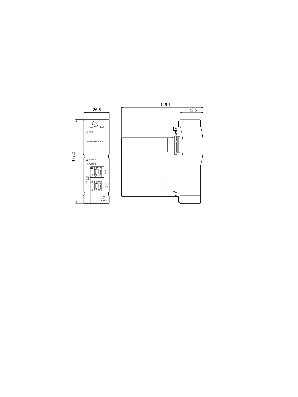
9
9.1
PROFINET communication module
Figure 9-1 Communication Module 3RW4900-0NC00
PROFINET Communication Module for SIRIUS Soft Starter 3RW44
Manual, 12/2013, A5E31996495002A/RS-AA/001
69
Page 70
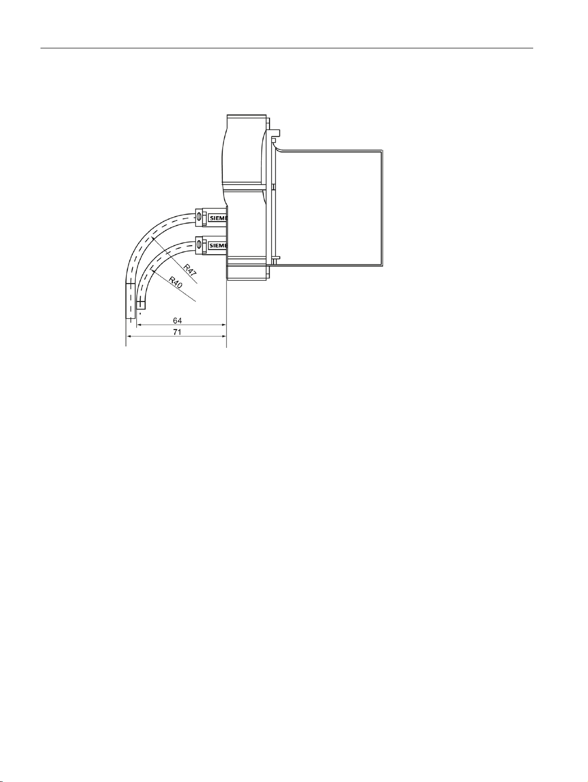
Dimension drawings
9.2
PROFINET communication module with connectors
9.2 PROFINET communication module with connectors
Figure 9-2 PROFINET communication module in installed/connected state with straight connectors
PROFINET Communication Module for SIRIUS Soft Starter 3RW44
70 Manual, 12/2013, A5E31996495002A/RS-AA/001
Page 71
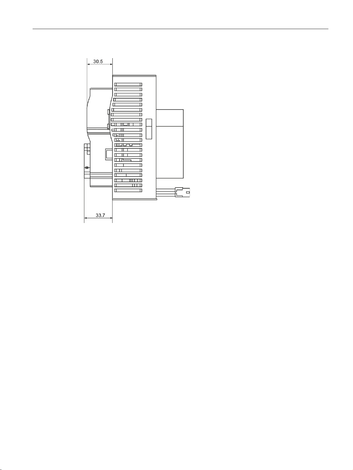
Dimension drawings
9.2 PROFINET communication module with connectors
Figure 9-3 PROFINET communication module in installed/connected state with angled connectors
PROFINET Communication Module for SIRIUS Soft Starter 3RW44
Manual, 12/2013, A5E31996495002A/RS-AA/001
71
Page 72

Dimension drawings
9.2 PROFINET communication module with connectors
PROFINET Communication Module for SIRIUS Soft Starter 3RW44
72 Manual, 12/2013, A5E31996495002A/RS-AA/001
Page 73
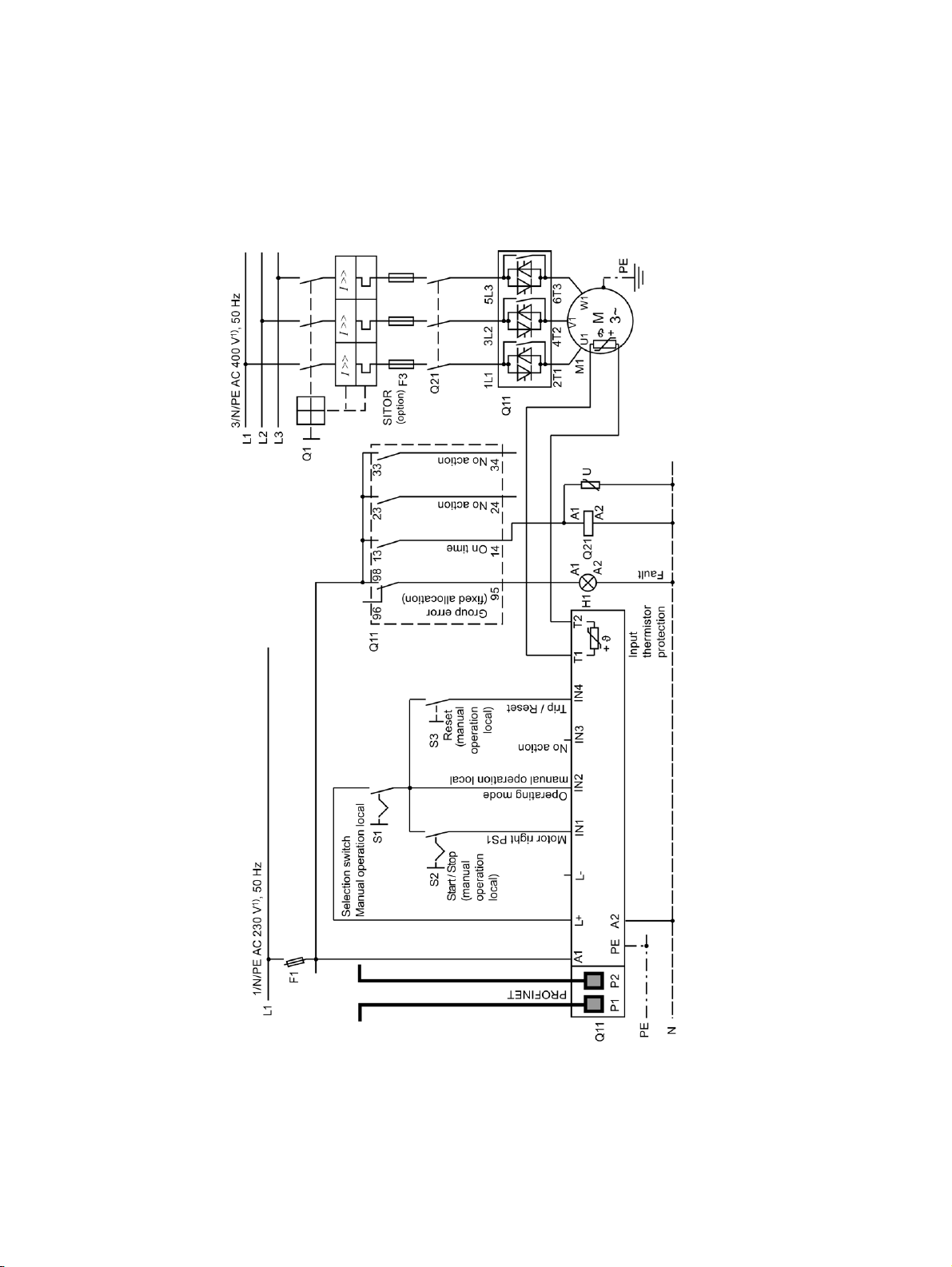
10
Figure 10-1 Control via PROFINET with switchover to manual operation local mode (e.g., at the
control cabinet)
PROFINET Communication Module for SIRIUS Soft Starter 3RW44
Manual, 12/2013, A5E31996495002A/RS-AA/001
73
Page 74

Circuit diagram example
PROFINET Communication Module for SIRIUS Soft Starter 3RW44
74 Manual, 12/2013, A5E31996495002A/RS-AA/001
Page 75

A
A.1
Data formats and data records
A.1.1
Process data and process images
Process image
Process data
Process image:
(16 O, DO 0.0 to DO 1.7)
(16 I, DI 0.0 to DI 1.7)
Outputs
The process image is a component of the system memory of the CPU. At the start of the
cyclic program, the signal states of the inputs are transferred to the process image of the
inputs. At the end of the cyclic program, the process image of the outputs is transferred to
the IO device as a signal state.
For soft starters with PROFINET, the following process image is available:
● Process image with 2 bytes outputs / 2 bytes inputs (16 O/16 I)
The following table contains the the process data and process images:
DO 0.0 Motor right
DO 0.1 Motor left
DO 0.2 Not assigned
DO 0.3 Trip Reset
DO 0.4 Emergency start
DO 0.5 Not assigned
DO 0.6 Slow speed
DO 0.7 Not assigned
DO 1.0 Output 1
DO 1.1 Output 2
PROFINET Communication Module for SIRIUS Soft Starter 3RW44
Manual, 12/2013, A5E31996495002A/RS-AA/001
75
Page 76
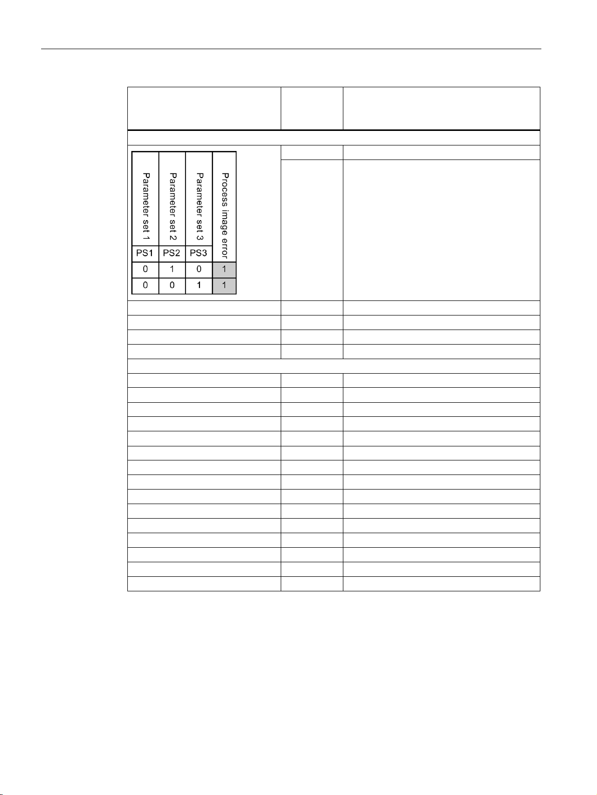
Appendix
Process data
Process image:
(16 O, DO 0.0 to DO 1.7)
(16 I, DI 0.0 to DI 1.7)
Outputs
Inputs
Control data
A.1 Data formats and data records
⇐ DO 1.2 Parameter set bit 0
⇐ DO 1.3 Parameter set bit 1
DO 1.4 Not assigned
DO 1.5 Not assigned
DO 1.6 Not assigned
DO 1.7 Lock quickstop
DI 0.0 Ready (automatic)
DI 0.1 Motor On
DI 0.2 Group error
DI 0.3 Group warning
DI 0.4 Input 1
DI 0.5 Input 2
DI 0.6 Input 3
DI 0.7 Input 4
DI 1.0 Motor current I
DI 1.1 Motor current I
DI 1.3 Motor current I
DI 1.4 Motor current I
DI 1.5 Motor current I
DI 1.6 Manual operation local mode
DI 1.7 Ramp mode
act-bit0
act-bit1
act-bit2
act-bit3
act-bit4
PROFINET Communication Module for SIRIUS Soft Starter 3RW44
76 Manual, 12/2013, A5E31996495002A/RS-AA/001
The soft starter evaluates a large amount of operating, diagnostic, and statistical data.
Data that are transferred to the soft starter, e.g., switching command Motor left, Trip Reset,
etc.
Data format: Bit
Page 77
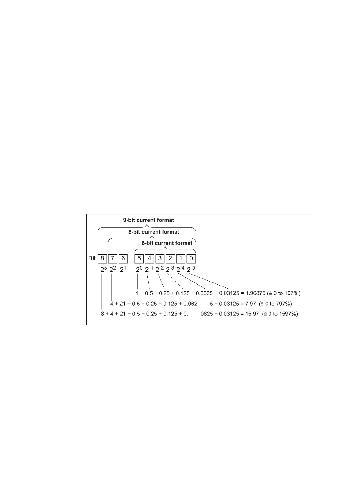
Appendix
Alarms
Diagnostics
Current formats
A.1 Data formats and data records
Data that are transferred from the soft starter and that indicate the current operating status,
e.g., Motor left, etc.
Data format: Bit
Data that are transferred from the soft starter and that indicate the current operating status,
e.g., Overload fault, etc.
Data format: Bit
Current values are coded in different current formats, namely in
6-bit current format,
8-bit current format, and
9-bit current format:
Current values are
● Motor current I
● Phase currents I
(6-bit current format)
max
, I
L2max
, I
L3max
L1max
(8-bit current format)
● Last trigger current (9-bit current format)
● Maximum tripping current (9-bit current format)
PROFINET Communication Module for SIRIUS Soft Starter 3RW44
Manual, 12/2013, A5E31996495002A/RS-AA/001
77
Page 78

Appendix
Statistics data for device service life
Statistical data for maximum pointers
A.1 Data formats and data records
● Operating hours
The soft starter records 2 operating hour values:
– The operating hours of the motor.
This indicates how long the motor was switched on.
– The operating hours of the device (soft starter).
This indicates how long the 115 V AC or 230 V AC voltage supply of the soft starter
was switched on.
Both operating hour values are recorded in data record 95 - "Read statistics". They
are entered in the "Operating hours" data field at 1-second intervals.
The operating hours are recorded in the range from 0 to 2
increments.
● Number of overload trips
The soft starter counts the number of overload trips in the range 0 to 65535.
32
seconds in 1-second
● Number of starts motor right/left
The soft starter counts the number of starts in the range 0 to 2
Example: If current flows in the main circuit after the "Motor On" command, the value is
incremented by 1.
● Number of starts output 1 to 4
● Motor current I
max.
The soft starter measures the current in all 3 phases and displays the current of the
highest loaded phase as a percentage [%] of the set current I
Data format: 1 byte, 8-bit current format
Example: Set current I
Indicated motor current 110 %
then corresponds to 60 A x 1.1 = 66 A
All 3 phase currents are available in data record 94
● Last trigger current
The soft starter measures the current in all 3 phases and displays the current that is
flowing in the highest loaded phase when tripping occurs as a percentage [%] of the set
current I
and in amperes [A]
e
Data format: 2 bytes, 9-bit current format
Example: Set current I
Indicated motor current 455 % then corresponds to 60 A x 4.55 = 273 A
= 60 A
e
= 60 A
e
32
.
e
Maximum pointers are used for preventive diagnostics:
● The maximum measured value is stored in the device.
● The higher-level PLC can retrieve the measured value at any time.
● The higher-level PLC can reset the measured value at any time.
PROFINET Communication Module for SIRIUS Soft Starter 3RW44
78 Manual, 12/2013, A5E31996495002A/RS-AA/001
Page 79

Appendix
Reading/writing of data records with STEP 7
Additional information
A.1 Data formats and data records
The following data are available as a maximum pointer:
● Number of overload trips.
● Phase current I
L1max
to I
L3max
a percentage [%] of set current I
Data format: 1 byte each, 8-bit current format.
Both the measured maximum and minimum phase current in bypass operation are stored
per phase.
● Minimum and maximum phase-to-phase voltages U
Minimum and maximum line frequency in 0.5 Hz resolution.
You can access the data records of the soft starter from the user program.
● Writing data records:
By calling SFB 53 "WR_REC"
● Reading data records:
By calling SFB 52 "RD_REC"
You can find additional information about the SFBs in:
● Reference manual
"System Software for S7-300/400, System and Standard Functions"
and I
to I
L1min
and in amperes [A]
e
. Maximum and minimum phase current as
L3min
- ULy as RMS values in 0.1 V.
Lx
● STEP 7 online help
PROFINET Communication Module for SIRIUS Soft Starter 3RW44
Manual, 12/2013, A5E31996495002A/RS-AA/001
79
Page 80
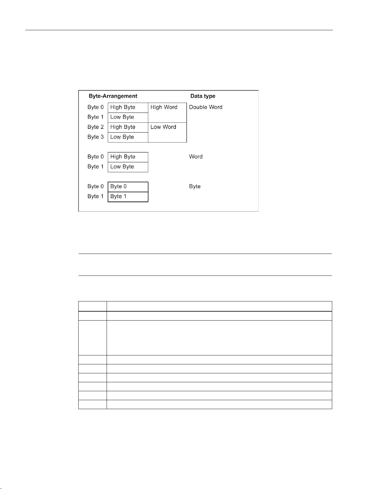
Appendix
Byte arrangements
A.1.2
Data record 68 - Read/write process image of the outputs (PIO)
Note
Byte
Meaning
A.1 Data formats and data records
When data longer than one byte is stored, the bytes are arranged as follows ("big endian"):
Note that data record 68 is overwritten by the cyclic process image in automatic mode!
Header
0 Coordination (access via:)
0x20 Acyclic bus channel - Startup data record
0x30 Acyclic bus channel - ES tool ("Soft Starter ES" software)
0x40 Local device interface - ES tool ("Soft Starter ES" software)
1 - 3 Reserved = 0
Process image of the outputs
4 Process data DO 0.0 to DO 0.7, table below
5 Process data DO 1.0 to DO 1.7, table below
6 Reserved = 0
7 Reserved = 0
PROFINET Communication Module for SIRIUS Soft Starter 3RW44
80 Manual, 12/2013, A5E31996495002A/RS-AA/001
Page 81

Appendix
Process data
Process image
(16 O (outputs), DO 0.0 to DO 1.7)
Note
A.1 Data formats and data records
DO 0.0 Motor right
DO 0.1 Motor left
DO 0.2 Not assigned (brake)
DO 0.3 Trip Reset
DO 0.4 Emergency start
DO 0.5 Not assigned (self-test)
DO 0.6 Slow speed
DO 0.7 Not assigned
DO 1.0 Output 1
DO 1.1 Output 2
DO 1.2 Parameter set bit 0
DO 1.3 Parameter set bit 1
DO 1.4 Not assigned
DO 1.5 Not assigned
DO 1.6 Not assigned
DO 1.7 Lock quickstop
In "Automatic mode", the PLC provides the process image of the outputs. In this case, when
data record 68 is read at the local device interface, the process image of the outputs is
returned as it was transferred from the PLC.
PROFINET Communication Module for SIRIUS Soft Starter 3RW44
Manual, 12/2013, A5E31996495002A/RS-AA/001
81
Page 82
Appendix
A.1.3
Data record 69 - Process image of the inputs (PII)
Byte
Meaning
Process data
Process image:
(16 I (inputs), DI 0.0 to DI 1.7)
A.1 Data formats and data records
Process image of the inputs
0 Process data DI 0.0 to DI 0.7, table below
1 Process data DI 1.0 to DI 1.7, table below
2 Reserved = 0
3 Reserved = 0
DI 0.0 Ready (automatic)
DI 0.1 Motor On
DI 0.2 Group error
DI 0.3 Group warning
DI 0.4 Input 1
DI 0.5 Input 2
DI 0.6 Input 3
DI 0.7 Input 4
DI 1.0 Motor current I
DI 1.1 Motor current I
DI 1.2 Motor current I
DI 1.3 Motor current I
DI 1.4 Motor current I
DI 1.5 Motor current I
DI 1.6 Manual operation local mode
DI 1.7 Ramp mode
act-bit0
act-bit1
act-bit2
act-bit3
act-bit4
act-bit5
PROFINET Communication Module for SIRIUS Soft Starter 3RW44
82 Manual, 12/2013, A5E31996495002A/RS-AA/001
Page 83

Appendix
A.1.4
Data record 72 - Log list - Read device error
Byte
Meaning
Value range
Increment
Comment
Note
Object No.
Device error alarms
A.1 Data formats and data records
0 ... 3 Operating hours
device
4 ... 5 Object number
device error
6 ... 9 Operating hours
device
10 ... 11 Object number
device error
etc.
120 ... 123 Operating hours
device
124 ... 125 Object number
device error
0 … 232 s 1 second Entry 1 = oldest
entry
0 … ±32767 1
0 … 232 s 1 second Entry 2 = second
oldest entry
0 … ±32767 1
0 … 232 s 1 second Entry 21 = last,
newest entry
0 … ±32767 1
This data record can accommodate 21 entries. When all locations have been written, the first
entry is overwritten again.
The newest entry is entered at the end of the data record. The remaining entries are moved
up one entry.
The following alarms can be entered:
452 Heat sink thermistor defective
1466 Switching element 1 failed
1467 Switching element 2 failed
1468 Switching element 3 failed
1417 Bypass element defective
PROFINET Communication Module for SIRIUS Soft Starter 3RW44
Manual, 12/2013, A5E31996495002A/RS-AA/001
83
Page 84
Appendix
A.1.5
Data record 73 - Log list - Read trips
Byte
Meaning
Value range
Increment
Comment
Note
Object No.
Trips alarms
A.1 Data formats and data records
0 ... 3 Operating hours
device
4 ... 5 Object number
trips
6 ... 9 Operating hours
device
10 ... 11 Object number
trips
etc.
120 ... 123 Operating hours
device
124 ... 125 Object number
trips
0 ... 232 s 1 second
Entry 1 = oldest
0 ... ± 32767 1
0 ... 232 s 1 second Entry 2 = second
0 ... ± 32767 1
0 ... 232 s 1 second Entry 21 = last,
0 ... ± 32767 1
entry
oldest entry
newest entry
This data record can accommodate 21 entries. When all locations have been written, the first
entry is overwritten again.
The newest entry is entered at the end of the data record. The remaining entries are moved
up one entry.
The following alarms can be entered:
309 Contact block overload
317 Electronics supply voltage too low
319 No main power
324 Temperature sensor overload
325 Temperature sensor wire break
326 Temperature sensor short-circuit
327 Thermal motor model overload
334 Current limit exceeded
335 Current limit undershot
339 Motor stalled - switched off
341 Asymmetry tripping
343 Ground fault tripping
355 Process image error
365 Incorrect parameter value
(Obj. No.) Object number of incorrect parameter
1407 Electronics supply voltage too high
PROFINET Communication Module for SIRIUS Soft Starter 3RW44
84 Manual, 12/2013, A5E31996495002A/RS-AA/001
Page 85
Appendix
Object No.
Trips alarms
A.1.6
Data record 75 - Log list - Read events
Byte
Meaning
Value range
Increment
Comment
Note
A.1 Data formats and data records
1408 No load
1409 Loss of phase L1
1410 Loss of phase L2
1411 Loss of phase L3
1421 Impermissible Ie/CLASS setting
1479 Phase angle control failure
1481 System voltage too high
1482 Current measuring range exceeded
0 ... 3 Operating hours
device
4 ... 5 Object number
events
6 ... 9 Operating hours
device
10 ... 11 Object number
events
etc.
120 ... 123 Operating hours
device
124 ... 125 Object number
events
*) + Incoming event
- Outgoing event
0 ... 232 s 1 second
Entry 1 = oldest
0 ... ± 32767 *) 1
0 ... 232 s 1 second Entry 2 = second
0 ... ± 32767 *) 1
0 ... 232 s 1 second Entry 21 = last,
0 ... ± 32767 *) 1
entry
oldest entry
newest entry
This data record can accommodate 21 entries. When all locations have been written, the first
entry is overwritten again.
The newest entry is entered at the end of the data record. The remaining entries are moved
up one entry.
PROFINET Communication Module for SIRIUS Soft Starter 3RW44
Manual, 12/2013, A5E31996495002A/RS-AA/001
85
Page 86

Appendix
Object No.
Events alarms
Comment
Warnings
Actions
A.1.7
Data record 81 - Read basic setting of data record 131
A.1.8
Data record 82 - Read basic setting of data record 132
A.1 Data formats and data records
The following alarms can be entered:
324 Temperature sensor overload ±
325 Temperature sensor wire break ±
326 Temperature sensor short-circuit ±
327 Thermal motor model overload ±
334 Current limit exceeded ±
335 Current limit undershot ±
340 Asymmetry detected ±
342 Ground fault detected ±
310 Emergency start active ±
357 Automatic mode +
358 Manual bus mode +
359 Manual operation local mode +
360 Connection abort in manual mode ±
363 Maximum pointer reset +
365 Incorrect parameter value +
(Obj. No.) Object number of incorrect parameter
366 Parameters cannot be changed in ON state +
(Obj. No.) Object number of incorrect parameter
368 Parameters disabled CPU/master active ±
369 Basic factory settings restored +
376 FW update successful +
1302 Log list trips deleted +
1303 Log list events deleted +
1422 Thermal motor model deactivated
1520 Energy saving mode active ±
+ Incoming event
± Incoming/outgoing event
PROFINET Communication Module for SIRIUS Soft Starter 3RW44
86 Manual, 12/2013, A5E31996495002A/RS-AA/001
Data record 81 corresponds in structure and content to data record 131. Data record 81
supplies the default values for all parameters of data record 131.
Data record 82 corresponds in structure and content to data record 132. Data record 82
supplies the default values for all parameters of data record 132.
Page 87

Appendix
A.1.9
Data record 83 - Read basic setting of data record 133
A.1.10
Data record 92 - Read device diagnostics
Byte
Bit
Alarm bit
Error No.*)
Meaning/acknowledgment
Switching/controlling
A.1 Data formats and data records
Data record 83 corresponds in structure and content to data record 133. Data record 83
supplies the default values for all parameters of data record 133.
00 Ready (automatic) - Device is ready for operation via host (e.g.,
01 Motor right - Contact block 1 is switched on,
02 Motor left - Contact block 2 is switched on,
03 Contact block overload 5, 24 e.g., power semiconductor too hot, causing
04 Contact block defective 9, 24 e.g., contactor is fusion-welded/jammed or
05 Emergency start active - Alarm bit is deleted when emergency start is
06 Group error - At least 1 error that generates an Error No.
07 Group warning - At least 1 warning is pending,
10 Reserved = 0 -
11 No main power 17, 24 Alarm bit is deleted when the cause of
12 Reserved = 0 -
13 Start mode active -
14 Stop mode active 15 Reserved = 0 -
16 Electrical braking active - Brake output is switched on by the soft
17 Slow speed active - Alarm bit is updated continually.
PLC), alarm bit is updated continually.
alarm bit is updated continually.
alarm bit is updated continually.
motor to trip.
Alarm bit is deleted when the cause of
tripping has been eliminated and
acknowledged with "Trip Reset".
power semiconductor has failed.
Alarm bit can only be deleted by switching
the supply voltage On and Off once the
cause of the error has been eliminated.
deactivated.
is set.
Alarm bit is deleted when the cause of
tripping has been eliminated and
acknowledged with "Trip Reset, Autoreset,
OFF command"
alarm bit is updated continually.
tripping has been eliminated and
acknowledged with "Trip Reset".
Alarm bit is updated continually.
starter,
alarm bit is updated continually.
PROFINET Communication Module for SIRIUS Soft Starter 3RW44
Manual, 12/2013, A5E31996495002A/RS-AA/001
87
Page 88

Appendix
Byte
Bit
Alarm bit
Error No.*)
Meaning/acknowledgment
Protective function: Motor / cable / short-circuit
A.1 Data formats and data records
20 Temperature sensor overload 4, 24 Overload detected, alarm bit is updated
continually.
21 Temperature sensor wire break 6, 24 Thermistor circuit interrupted,
alarm bit is updated continually.
22 Temperature sensor short-circuit 1, 24 Short-circuit in thermistor circuit,
alarm bit is updated continually.
23 Thermal motor model overload 4, 24 Overload detected, alarm bit is updated
continually.
24 Overload tripping 4, 24 Motor is tripped due to a detected overload.
Alarm bit is deleted when the cause of
tripping has been eliminated and
acknowledged with "Trip Reset"/"Autoreset".
25 Idle time active - Alarm bit is updated continually.
26 Cooling time active - Alarm bit is updated continually.
27 Reserved = 0 -
0...2
3
Reserved = 0 -
33 Current limiting active -
4...6
3
Reserved = 0 -
37 Input control - Device receives control commands via the
inputs,
alarm bit is updated continually.
40 Asymmetry detected - Asymmetry is present, alarm bit is updated
continually.
41 Asymmetry tripping 9, 24 Tripping of the motor due to asymmetry.
Alarm bit is deleted when the cause of
tripping has been eliminated and
acknowledged with "Trip Reset".
42 Current limit exceeded 7, 24 Limit exceeded,
alarm bit is updated continually.
43 Current limit undershot 8, 24 Limit undershot,
alarm bit is updated continually.
44 Current limit tripping 7, 24 or 8,
24
Alarm bit is deleted when the cause of
tripping has been eliminated and
acknowledged with "Trip Reset".
45 Reserved = 0 -
46 Reserved = 0 -
47 Motor stalled - switched off 9, 24 Trip, stalling current detected for longer than
the permitted stalling time. Alarm bit is
deleted when the cause of tripping has been
eliminated and acknowledged with "Trip
Reset".
50 Input 1 - States of the inputs:
51 Input 2 52 Input 3 -
"1" = active, HIGH level is present
"0" = inactive, LOW level is present
Alarm bit is updated continually.
53 Input 4 -
PROFINET Communication Module for SIRIUS Soft Starter 3RW44
88 Manual, 12/2013, A5E31996495002A/RS-AA/001
Page 89

Appendix
Byte
Bit
Alarm bit
Error No.*)
Meaning/acknowledgment
Communication
A.1 Data formats and data records
4...7
5
Reserved = 0 -
60 Ground fault detected - Ground fault is present,
alarm bit is updated continually.
61 Ground fault tripping 9, 24 Tripping of motor due to ground fault.
Alarm bit is deleted when the cause of
tripping has been eliminated and
acknowledged with "Trip Reset".
62 Quick stop active - Tripping of the motor due to quick stop.
Alarm bit is deleted when the cause of
tripping has been eliminated and
acknowledged with "Trip Reset".
63 Reserved = 0 -
64 Trip Reset performed - Alarm bit is deleted by an update or by a
"Trip Reset" in ready for operation status.
65 Trip Reset not possible - Tripping cause is still present.
Alarm bit is deleted by an update (new "Trip
Reset") or by a "Trip Reset" in ready for
operation status.
66 Maximum pointer reset - Alarm bit is always deleted when
acknowledged with "Trip Reset".
67 Electronics supply voltage too low 17, 24 Alarm bit is deleted automatically when the
cause of tripping has been eliminated.
70 Bus error - Watchdog timer of DP interface has
71 CPU/master Stop - PLC program is no long being executed,
72 Automatic mode - Automatic (PLC controlled),
73 Manual bus mode - Manual mode via fieldbus (OPC controlled),
74 Manual operation local mode - Manual mode via local device interface,
75 Reserved = 0 -
76 Connection abort in manual mode - During manual mode, the related
77 Process image error 24, 26 Process image of the outputs contains an
elapsed,
alarm bit is updated continually.
alarm bit is updated continually.
alarm bit is updated continually.
alarm bit is updated continually.
(OPC controlled), alarm bit is updated
continually.
communication connection was interrupted,
alarm bit is updated continually.
impermissible bit combination, alarm bit is
deleted continually when cause of tripping
has been eliminated.
PROFINET Communication Module for SIRIUS Soft Starter 3RW44
Manual, 12/2013, A5E31996495002A/RS-AA/001
89
Page 90

Appendix
Byte
Bit
Alarm bit
Error No.*)
Meaning/acknowledgment
Parameters
Device function
A.1 Data formats and data records
80 Parameter assignment active - Alarm bit is updated continually.
81 Incorrect parameter value 16, 24 Alarm bit is always deleted when
acknowledged with "Trip Reset" or valid
parameters have been received.
82 Parameters cannot be changed in ON state - Attempted parameter change while motor is
running or during relevant device function,
which has caused the trip.
Alarm bit is always deleted when
acknowledged with "Trip Reset" or valid
parameters have been received.
83 Parameters disabled CPU/master active - alarm bit is updated continually,
soft starter ignores parameters from the
PLC.
84 No external start parameters received -
5...7
8
Reserved = 0 -
0...2
9
Reserved = 0 -
93 Basic factory settings restored - Alarm bit is always deleted when
acknowledged with "Trip Reset".
4...5
9
Reserved = 0 -
96 FW update successful -
97 Reserved = 0 -
10 Faulty parameter number (low byte) - In conjunction with bytes 81 and 82, the ID
11 Faulty parameter number (high byte) -
No. indicates that first parameter not
accepted.
Alarm byte is always deleted when
acknowledged with "Trip Reset".
0...1
12
Reserved = 0 -
122 Impermissible Ie/CLASS setting -
3...7
12
Reserved = 0 -
130 Parameter set 1 active -
131 Parameter set 2 active -
132 Parameter set 3 active -
133 Reserved = 0 -
134 Parameter set change impermissible -
5...7
13
Reserved = 0 -
0...1
14
Reserved = 0 -
142 Motor heating active -
143 DC braking active -
144 Dynamic DC braking active -
145 Motor connection type star/delta -
146 Motor connection type inside delta -
147 Motor connection type unknown -
150 No load 17, 24
PROFINET Communication Module for SIRIUS Soft Starter 3RW44
90 Manual, 12/2013, A5E31996495002A/RS-AA/001
Page 91

Appendix
Byte
Bit
Alarm bit
Error No.*)
Meaning/acknowledgment
Switching/controlling
Protective function
Communication
A.1 Data formats and data records
151 Reserved = 0 17, 24
152 Loss of phase L1 17, 24
153 Loss of phase L2 17, 24
154 Loss of phase L3 17, 24
155 Main power rotation right -
156 Main power rotation left -
157 System voltage too high 17, 24
16 Reserved = 0 -
170 Output 1 active -
171 Output 2 active -
172 Output 3 active -
173 Output 4 active -
4...7
17
Reserved = 0 -
18 Reserved = 0 -
190 Electronics supply voltage too high 17, 24
191 Ready to start for motor ON -
192 Contact block short-circuited -
193 Bypass element defective 9, 24
194 Bypass element protective tripping 4, 24
195 Switching element 1 failed -
196 Switching element 2 failed -
197 Switching element 3 failed -
200 Thermal motor model deactivated -
1...2
20
Reserved = 0 -
203 Phase angle control failure -
4...7
20
Reserved = 0 -
210 Contact block cooling time active -
211 Contact block for Start too hot -
212 Current measuring range exceeded 9, 24
3...7
21
Reserved = 0 -
220 Automatic mode (redundant to bit 7.2) -
221 Manual bus mode (redundant to bit 7.3) -
222 Manual bus - PC controlled -
223 Manual operation local mode (redundant to bit
7.4)
224 Manual operation local - input controlled -
225 Manual operation local - OCM controlled -
226 Manual operation local - PC controlled -
-
PROFINET Communication Module for SIRIUS Soft Starter 3RW44
Manual, 12/2013, A5E31996495002A/RS-AA/001
91
Page 92

Appendix
Byte
Bit
Alarm bit
Error No.*)
Meaning/acknowledgment
Prewarnings
Energy saving function
A.1 Data formats and data records
227 Reserved = 0 -
23 Reserved = 0 -
0...1
24
Reserved = 0 -
242 Prewarning limit - remaining time for tripping
undershot
243 Prewarning limit - motor heating overshot -
4...7
24
Reserved = 0 -
25 Reserved = 0 -
26 Reserved = 0 -
27 Reserved = 0 -
280 FW update rejected -
1...7
28
Reserved = 0 -
29 Reserved = 0 -
30 Reserved = 0 -
31 Reserved = 0 -
1...5
36
Reserved = 0 -
366 Start_Pause command is pending -
367 Energy saving mode active -
37 Reserved = 0 -
-
-
*) PROFINET error numbers
PROFINET Communication Module for SIRIUS Soft Starter 3RW44
92 Manual, 12/2013, A5E31996495002A/RS-AA/001
Page 93
Appendix
A.1.11
Data record 93 - Write commands
Byte
Meaning
Comment
Header
Command
Code
Command
Meaning
Transition to manual mode. The soft starter switches to manual bus mode
Initiate a restart (same as after power ON), e.g., after reassignment of the
A.1 Data formats and data records
Structure of the command data record
0 Coordination 0x20 Write via C1 channel (PLC)
1 ... 3 Reserved = 0
4 Number of commands Value range 1 ... 5
Number of subsequent valid commands
5 Command 1 Sequential no., see table below
6 Command 2 Optional (coding, see table below)
7 Command 3 Optional (coding, see table below)
8 Command 4 Optional (coding, see table below)
9 Command 5 Optional (coding, see table below)
1-byte
commands
0 Reserved = 0 No function
1 Trip Reset Resetting and acknowledging of error messages
2 Emergency start ON Switch on emergency start
3 Emergency start OFF Switch off emergency start
4 Automatic mode Transition to automatic mode (control by CPU/master)
5 Manual mode
6 Basic factory settings Restore the basic factory settings of the parameters.
7 Reset maximum pointer The measured values for preventive diagnostics are deleted (= 0).
9 Restart
10 Parameters disabled
11 Parameters disabled
13 Log list - Delete trips Delete log list of recorded error causes.
14 Log list - Delete events Delete log list of recorded alarms and specific actions.
CPU/master ON
CPU/master OFF
or manual operation local mode depending on the interface via which the
command is received. This command can be used to obtain control
priority but not to give it up.
station address.
Parameter assignment by the parameter-assigning CPU or master is not
possible, or its parameters are ignored.
Parameter assignment by the parameter-assigning CPU or master is
possible.
PROFINET Communication Module for SIRIUS Soft Starter 3RW44
Manual, 12/2013, A5E31996495002A/RS-AA/001
93
Page 94

Appendix
A.1.12
Data record 94 - Read measured values
Byte
Bit
Meaning
Value range/ [coding]
Increment
Comment
Measured values
A.1 Data formats and data records
0 Phase current IL1 (%) 0 ... 797 % / [0 ... 255] 3.125 % 8-bit current format
1 Phase current IL2 (%) 0 ... 797 % / [0 ... 255] 3.125 % 8-bit current format
2 Phase current IL3 (%) 0 ... 797 % / [0 ... 255] 3.125 % 8-bit current format
3 Reserved = 0
4 ... 5 Remaining motor cooling time 0 ... 1 800 s / [0 ... 18 000] 0.1 s
0...6
6
Motor heating 0 ... 200 % / [0 ... 100] 2 %
67 Asymmetry ≥ 40% No asymmetry [0]
Asymmetry (≥ 40%) [1]
7 Asymmetry 0 ... 100 % / [0 ...100] 1 %
8 ...15 Reserved = 0
16 Output frequency 0 ... 100 Hz / [0 ... 200] 0.5 Hz
17 ... 19 Reserved = 0
20 Line frequency 0 ... 100 Hz / [0 ... 200] 0.5 Hz
21 Reserved = 0
22 ... 23 Line-to-line voltage U
24 ... 25 Line-to-line voltage U
26 ... 27 Line-to-line voltage U
(rms) 0 ... 1500 V / [0 ... 15000] 0.1 V
L1-L2
(rms) 0 ... 1500 V / [0 ... 15000] 0.1 V
L2-L3
(rms) 0 ... 1500 V / [0 ... 15000] 0.1 V
L3-L1
28 ... 31 Phase current IL1 (rms) 0 ... 20000 A / [0 ... 2000000] 0.01 A
32 ... 35 Phase current IL2 (rms) 0 ... 20000 A / [0 ... 2000000] 0.01 A
36 ... 39 Phase current IL3 (rms) 0 ... 20000 A / [0 ... 2000000] 0.01 A
40 ... 41 Electronics supply voltage 0 ... 1500 V / [0 ... 15000] 0.1 V
42 Heatsink temperature -40 ... 127 °C / [-40 ... 127] 1 °C
43 Contact block heating 0 ... 250 °C / [0 ... 250] 1 °C
44 ... 45 Remaining cooling time of contact block 0 ... 1800 s/ [0 ... 18000] 0.1 s
46 ... 47 Remaining time for tripping of thermal
0 ... 10000 s/ [0 ... 10000] 1 s
motor model
48 ... 51 Output power 0 ... 2147483 W /
0.1 W
[0 ... 21474830]
52 ... 63 Reserved = 0
PROFINET Communication Module for SIRIUS Soft Starter 3RW44
94 Manual, 12/2013, A5E31996495002A/RS-AA/001
Page 95

Appendix
A.1.13
Data record 95 - Read statistical data
Byte
Bit
Meaning
Value range/ [coding]
Increment
Comment
Statistics
A.1 Data formats and data records
0 Motor current I
0 ... 797 % / [0 ... 255] 3.125 % 8-bit current format
max ( %)
1 Reserved = 0
2 ... 3 Last trigger current I
A (%)
4 ... 7 Operating hours
8 ... 11 Number of starts motor right 0 ... 232-1 / [0 ... 232-1] 1
12 ... 15 Number of starts motor left 0 ... 232-1 / [0 ... 232-1] 1
16 ... 17 Number of motor overload trips 0 ... 65 535 / [0 ... 65 535] 1
18 ... 19 Reserved = 0
20 ... 23 Motor current I
24 ... 27 Last trigger current I
max (rms)
0 ... 20 000 A / [0 ... 2 000 000] 0.01 A
A (rms)
28 ... 31 Operating hours motor 0 ... 232-1 s / [0 ... 232-1] 1 s
32 ... 35 Operating hours motor current 18 ...
49.9 % x I
e (max )
36 ... 39 Operating hours motor current 50 ...
89.9 % x I
e (max )
40 ... 43 Operating hours motor current 90 ...
119.9 % x I
e (max)
44 ... 47 Operating hours motor current 120 ...
1000 % x I
e (max)
32
-1 s / [0 ... 232-1] 1 s
0 ... 2
32
-1 s / [0 ... 232-1] 1 s
0 ... 2
32
-1 s / [0 ... 232-1] 1 s
0 ... 2
32
0 ... 2
-1 s / [0 ... 232-1] 1 s
50 ... 51 Number of contact block overload trips 0 ... 232-1 s / [0 ... 232-1] 1
52 ... 53 Reserved = 0
54 ... 55 Reserved = 0
56 ... 59 Reserved = 0
60 ... 63 Number of braking stops 0 ... 232-1 s / [0 ... 232-1] 1
64 ... 67 Number of starts output 1 0 ... 232-1 s / [0 ... 232-1] 1
68 ... 71 Number of starts output 2 0 ... 232-1 s / [0 ... 232-1] 1
72 ... 75 Number of starts output 3 0 ... 232-1 s / [0 ... 232-1] 1
76 ... 79 Number of starts output 4 0 ... 232-1 s / [0 ... 232-1] 1
80 Reserved = 0
84 Reserved = 0
88 Reserved = 0
89 Reserved = 0
PROFINET Communication Module for SIRIUS Soft Starter 3RW44
Manual, 12/2013, A5E31996495002A/RS-AA/001
95
Page 96

Appendix
A.1.14
Data record 96 - Read maximum pointer
Byte
Bit
Meaning
Value range/ [coding]
Increment
Comment
A.1 Data formats and data records
4 Phase current I
5 Phase current I
6 Phase current I
(%) 0 ... 797 % / [0 ... 255] 3,125 % In bypass operation
L1 min
(%) 0 ... 797 % / [0 ... 255] 3,125 % In bypass operation
L2 min
(%) 0 ... 797 % / [0 ... 255] 3,125 % In bypass operation
L3 min
7 Reserved = 0 In bypass operation
8 Phase current I
9 Phase current I
10 Phase current I
(%) 0 ... 797 % / [0 ... 255] 3,125 % In bypass operation
L1 max
(%) 0 ... 797 % / [0 ... 255] 3,125 % In bypass operation
L2 max
(%) 0 ... 797 % / [0 ... 255] 3,125 % In bypass operation
L3 max
11 Reserved = 0
12 ... 13 Maximum tripping current I
(%) 0 ... 1000 % / [0 ... 320] 3,125 %
A max
14 ... 15 Number of motor overload trips 0 ... 65 535 / [0 ... 65 535] 1
16 ... 19 Maximum tripping current I
20 ... 23 Phase current I
24 ... 27 Phase current I
28 ... 31 Phase current I
32 ... 35 Phase current I
36 ... 39 Phase current I
40 ... 43 Phase current I
44 ... 45 Line-to-line voltage U
46 ... 47 Line-to-line voltage U
48 ... 49 Line-to-line voltage U
50 ... 51 Line-to-line voltage U
52 ... 53 Line-to-line voltage U
54 ... 55 Line-to-line voltage U
(rms) 0 ... 20 000 A / [0 ... 2 000 000] 0.01 A In bypass operation
L1 min
(rms) 0 ... 20 000 A / [0 ... 2 000 000] 0.01 A In bypass operation
L2 min
(rms) 0 ... 20 000 A / [0 ... 2 000 000] 0.01 A In bypass operation
L3 min
(rms) 0 ... 20 000 A / [0 ... 2 000 000] 0.01 A In bypass operation
L1 max
(rms) 0 ... 20 000 A / [0 ... 2 000 000] 0.01 A In bypass operation
L2 max
(rms) 0 ... 20 000 A / [0 ... 2 000 000] 0.01 A In bypass operation
L3 max
L1 - L2min
L2 - L3min
L3 - L1min
L1 - L2max
L2 - L3max
L3 - L1max
56 ... 57 Electronics supply voltage U
(rms) 0 ... 20 000 A / [0 ... 2 000 000] 0.01 A
A max
(rms) 0 ... 1500 V / [0 ... 15 000] 0.1 V Reset to 0 in the
(rms) 0 ... 1500 V / [0 ... 15 000] 0.1 V
(rms) 0 ... 1500 V / [0 ... 15 000] 0.1 V
event of phase failure
or switch-off of main
voltage.
(rms) 0 ... 1500 V / [0 ... 15 000] 0.1 V
(rms) 0 ... 1500 V / [0 ... 15 000] 0.1 V
(rms) 0 ... 1500 V / [0 ... 15 000] 0.1 V
(rms) 0 ... 1500 V / [0 ... 15 000] 0.1 V Reset to zero at
NS min
"Power on"
58 ... 59 Electronics supply voltage U
(rms) 0 ... 1500 V / [0 ... 15 000] 0.1 V
NS max
60 Maximum cooling temperature 1 ... -40 °C / [-40 ... 127] 1 °C
61 Maximum contact black heating 0 ... 250 % / [0 ... 250] 1 %
62 Minimum line frequency 0 ... 100 Hz / [0 ... 200] 0.5 Hz For line or phase loss
63 Maximum line frequency 0 ... 100 Hz / [0 ... 200] 0.5 Hz
64 ... 67 Operating hours -
motor current = 18 ... 49.9 % x l
68 ... 71 Operating hours -
motor current = 50 ... 89.9 % x l
72 ... 75 Operating hours -
motor current = 90 ... 119.9 % x l
76 ... 79 Operating hours -
motor current = 120 ... 1000 % x l
e
e
e
e
32
-1 s / [0 ... 232-1] 1 s
0 ... 2
32
0 ... 2
-1 s [0 ... 232-1] 1 s
32
0 ... 2
-1 s [0 ... 232-1] 1 s
1 s
80 ... 83 Operating hours device 0 ... 232-1 s / [0 ... 232-1] 1 s
84 ... 85 Reserved = 0
PROFINET Communication Module for SIRIUS Soft Starter 3RW44
96 Manual, 12/2013, A5E31996495002A/RS-AA/001
Page 97

Appendix
A.1.15
Data records 131, 141, 151 - Technology parameter 2: Read/write record 1, 2, 3
Byte
Bit
Value
Comment
Header
Object
No.
Byte
Bit
Meaning
Only in
data
record
131
Value range/ [coding]
Factor
A.1 Data formats and data records
0 Coordination 0x20 Write via C1 channel (PLC)
1 ... 3 Reserved = 0
120 4 ... 7 Device functions_2 X
1 8 ... 11 Device functions_1 X
130 12 Rated operating current Ie 0 ... 2 000 A [0 ... 200 000] 0.01 A
3 160 Load type X 3-phase [0]
4 161 Protection against voltage failure X
• No [0]
• Yes [1]
16
2...7
Reserved = 0
136 17 Prewarning limit motor heat build-up X 0 ... 95 % [0 ... 19] 5 %
5 18
0...2
Response to thermal motor model overload X
• Tripping without restart [0]
• Tripping with restart [1]
• Warning [2]
18
6 19
3...7
Reserved = 0
0...4
Tripping class X
• CLASS 5 (10a) [3]
• CLASS 10 [0]
• CLASS 15 [4]
• CLASS 20 [1]
• CLASS 30 [2]
• CLASS OFF [15]
19
5...7
Reserved = 0
7 20 Pre-charge time X 60 ... 1 800 s [2 ... 60] 30 s
8 21 Idle time X 0 ... 255 s [0 ... 255] 1 s
137 22 ... 23 Prewarning limit value tripping reserve X 0 ... 500 s [0 ... 500] 1 s
10 24
0...1
Response to temperature sensor overload X
• Tripping without restart [0]
• Tripping with restart [1]
• Warning [2]
24
9 24
2...3
Reserved = 0
4...6
Temperature sensor X
• Deactivated [0]
• Thermo click [1]
• PTC-type A [2]
PROFINET Communication Module for SIRIUS Soft Starter 3RW44
Manual, 12/2013, A5E31996495002A/RS-AA/001
97
Page 98

Appendix
Object
No.
Byte
Bit
Meaning
Only in
data
record
131
Value range/ [coding]
Factor
A.1 Data formats and data records
12 247 Temperature sensor monitoring X
• No [0]
• Yes [1]
25 ... 26 Reserved = 0
15 28 Minimum current limit 18.75 ... 100 % [6 ... 32] 3.125 %
16 29 Maximum current limit 50 ... 150 % [16 ... 48] 3.125 %
30 ... 31 Reserved = 0
32
14 326 Response to current limit value violation X
0...5
Reserved = 0
• Warning [0]
• Tripping [1]
327 Reserved = 0
33
140 332 Response to overload - contact block X
0...1
Reserved = 0
• Tripping without restart [0]
• Tripping with restart [1]
33
21 34
34
20 346 Response to asymmetry X
4...7
Reserved = 0
0...2
Asymmetry limit X 30 ... 60 % [3 ... 6] 10 %
3...5
Reserved = 0
• Warning [0]
• Tripping [1]
22 347 Response to ground fault X
• Warning [0]
• Tripping [1]
35 ... 44 Reserved = 0
47 45 Braking torque 20 ... 100 % [4 ... 20] 5 %
46 ... 47 Reserved = 0
40 48 Start voltage 20 ... 100 % [4 ... 20] 5 %
49 Reserved = 0
42 50 Current limiting value
98 Manual, 12/2013, A5E31996495002A/RS-AA/001
PROFINET Communication Module for SIRIUS Soft Starter 3RW44
• 3RW442/3/4: 125 ... 550 %
[40 ... 176]
• 3RW445: 125 ... 500 %
[40 ... 160]
• 3RW446: 125 ... 450 %
[40 ... 144]
Page 99

Appendix
Object
No.
Byte
Bit
Meaning
Only in
data
record
131
Value range/ [coding]
Factor
A.1 Data formats and data records
167 51
0...3
Starting mode
• Direct on line [0]
• Voltage ramp [1]
• Torque control [2]
• Motor heating [3]
• Voltage ramp + current limiting
[5]
• Torque control + current
limiting [6]
168 51
4...7
Stopping mode
• Coasting down [0]
• Torque control [2]
• Pump stop [3]
• DC braking [4]
• Combined braking [5]
35 52 ... 53 Substitute value X
54 ... 55 Reserved = 0
56
36 566 Group diagnosis X
0...5
Reserved = 0
• Disable [0]
• Enable [1]
34 567 Behavior on CPU/Master Stop X
• Switch substitute value [0]
• Hold last value [1]
57 ... 75 Reserved = 0
26 76 Input 1 action X
28 77 Input 2 - (see Input 1 action) X
30 78 Input 3 - (see Input 1 action) X
32 79 Input 4 - (see Input 1 action) X
80 ... 95 Reserved = 0
PROFINET Communication Module for SIRIUS Soft Starter 3RW44
Manual, 12/2013, A5E31996495002A/RS-AA/001
• No action (default) [0]
• Manual operation local mode
[6]
• Emergency start [7]
• Slow speed [10]
• Quick stop [11]
• Trip Reset [12]
• Motor right with PS1 [16]
• Motor left with PS1 [17]
• Motor right with PS2 [18]
• Motor left with PS2 [19]
• Motor right with PS3 [20]
• Motor left with PS3 [21]
99
Page 100

Appendix
Object
No.
Byte
Bit
Meaning
Only in
data
record
131
Value range/ [coding]
Factor
A.1 Data formats and data records
163 96 Output 1 action X
• No action (default) [0]
• Control source PIO DO 1.0
output 1 [1]
• Control source PIO DO 1.1
output 2 [2]
• Control source input 1 [6]
• Control source input 2 [7]
• Control source input 3 [8]
• Control source input 4 [9]
• Run-up [10]
• Operation/bypass [11]
• Coasting down [12]
• On time motor [13]
• Control command motor-on
[14]
• DC brake contactor [16]
• Device ON [18]
• Group warning [31]
• Group error [32]
• Bus error [33]
• Device error [34]
• Ready to start for motor ON
[38]
164 97 Output 2 action (see Output 1 action) X
165 98 Output 3 action (see Output 1 action) X
166 99 Output 4 action
100 ...
111
116 112 Breakaway time 0 ... 2 s [0 ... 200] 0.01 s
117 113 Breakaway voltage 40 ... 100 % [8 ... 20] 5 %
169 114 ...
115
170 116 ...
117
171 118 ...
119
172 120 Start torque 10 ... 100 % [2 ... 20] 5 %
118 121 Limiting torque 20 ... 200 % [4 ... 40] 5 %
100 Manual, 12/2013, A5E31996495002A/RS-AA/001
PROFINET Communication Module for SIRIUS Soft Starter 3RW44
Reserved = 0
Maximum starting time 0 ... 1 000 s [0 ... 10 000] 0.1 s 1)
Starting time 0 ... 360 s [0 ... 3 600] 0.1 s 1)
Stopping time 0 ... 360 s [0 ... 3 600] 0.1 s 1)
 Loading...