

Page 1
Industrial Controls
Load Feeders and Motor Starters
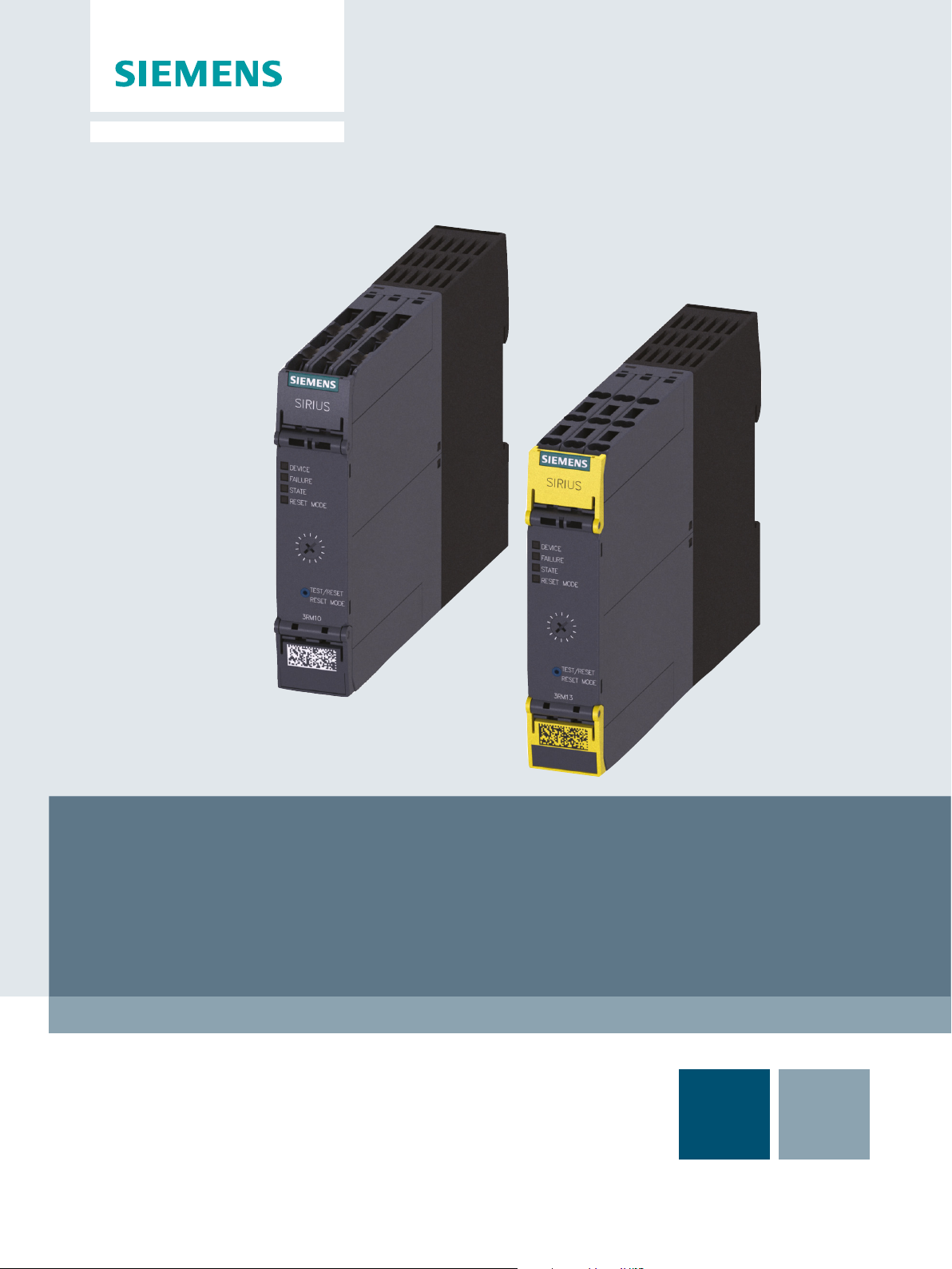
SIRIUS 3RM1 Motor Starter
Manual
Edition 06/2016
siemens.com
Page 2

Page 3

SIRIUS 3RM1 motor starter
___________________
___________________
___________________
___________________
___________________
___________________
___________________
___________________
___________________
___________________
___________________
___________________
___________________
Industrial Controls
Load feeders and motor starters
SIRIUS 3RM1 motor starter
Manual
06/2016
A5E0345285095020A/RS
Introduction
1
Product-specific safety
information
2
Description
3
Configuration
4
Mounting
5
Connection
6
Operator control and
monitoring
7
Service and maintenance
8
Technical data
9
Dimension drawings
10
Circuit diagrams
11
Typical circuits
A
Directives
B
-AE/005
Page 4
Siemens AG
Division Digital Factory
Postfach 48 48
90026 NÜRNBERG
GERMANY
3ZX1012-0RM10-2AC1
Ⓟ
Copyright © Siemens AG 2012.
All
Legal information
Warning notice system
DANGER
indicates that death or severe personal injury will result if proper precautions are not taken.
WARNING
indicates that death or severe personal injury may result if proper precautions are not taken.
CAUTION
indicates that minor personal injury can result if proper precautions are not taken.
NOTICE
indicates that property damage can result if proper precautions are not taken.
Qualified Personnel
personnel qualified
Proper use of Siemens products
WARNING
Siemens products may only be used for the applications described in the catalog and in the relevant technical
ambient conditions must be complied with. The information in the relevant documentation must be observed.
Trademarks
Disclaimer of Liability
This manual contains notices you have to observe in order to ensure your personal safety, as well as to prevent
damage to property. The notices referring to your personal safety are highlighted in the manual by a safety alert
symbol, notices referring only to property damage have no safety alert symbol. These notices shown below are
graded according to the degree of danger.
If more than one degree of danger is present, the warning notice representing the highest degree of danger will
be used. A notice warning of injury to persons with a safety alert symbol may also include a warning relating to
property damage.
The product/system described in this documentation may be operated only by
task in accordance with the relevant documentation, in particular its warning notices and safety instructions.
Qualified personnel are those who, based on their training and experience, are capable of identifying risks and
avoiding potential hazards when working with these products/systems.
Note the following:
documentation. If products and components from other manufacturers are used, these must be recommended
or approved by Siemens. Proper transport, storage, installation, assembly, commissioning, operation and
maintenance are required to ensure that the products operate safely and without any problems. The permissible
All names identified by ® are registered trademarks of Siemens AG. The remaining trademarks in this publication
may be trademarks whose use by third parties for their own purposes could violate the rights of the owner.
We have reviewed the contents of this publication to ensure consistency with the hardware and software
described. Since variance cannot be precluded entirely, we cannot guarantee full consistency. However, the
information in this publication is reviewed regularly and any necessary corrections are included in subsequent
editions.
for the specific
06/2016 Subject to change
rights reserved
Page 5

Table of contents
1 Introduction ........................................................................................................................................... 11
2 Product-specific safety information ........................................................................................................ 19
3 Description ............................................................................................................................................ 25
1.1 Responsibility of the user for system configuration and functionality ..................................... 11
1.2 Required basic knowledge ...................................................................................................... 11
1.3 Scope ...................................................................................................................................... 12
1.4 Definition ................................................................................................................................. 12
1.5 Conformity ............................................................................................................................... 12
1.6 Further documentation ............................................................................................................ 13
1.7 Siemens Industry Online Support ........................................................................................... 14
1.8 DataMatrix code ...................................................................................................................... 16
1.9 Quick navigation ..................................................................................................................... 17
2.1 General safety notes ............................................................................................................... 19
2.2 Safety information for hazardous areas .................................................................................. 20
2.3 Safety instructions for safety-related applications .................................................................. 21
2.4 Intended use ........................................................................................................................... 23
2.5 Current information about operational safety ......................................................................... 23
2.6 Declaration of conformity ........................................................................................................ 24
3.1 Overview ................................................................................................................................. 25
3.2 Applications ............................................................................................................................. 26
3.3 Hybrid technology ................................................................................................................... 27
3.4 Device versions ....................................................................................................................... 29
3.5 Functions ................................................................................................................................ 32
3.5.1 Switching the 3RM1 motor starter under normal operating conditions ................................... 32
3.5.1.1 Direct-on-line starter ............................................................................................................... 33
3.5.1.2 Reversing starter ..................................................................................................................... 34
3.5.2 Protective functions ................................................................................................................. 35
3.5.2.1 Overload protection ................................................................................................................. 35
3.5.2.2 Equipment protection .............................................................................................................. 35
3.5.2.3 Phase failure protection .......................................................................................................... 35
3.5.2.4 Asymmetry monitoring ............................................................................................................ 36
3.5.2.5 Thermal calculation method (motor memory module) ............................................................ 37
3.5.2.6 ATEX-certified motor overload protection in the case of 3RM11/3RM13 Failsafe ................. 38
SIRIUS 3RM1 motor starter
Manual, 06/2016, A5E0345285095020A/RS-AE/005
5
Page 6

Table of contents
4 Configuration ........................................................................................................................................ 57
3.5.3 Shutdown on malfunction ....................................................................................................... 42
3.5.4 Safety-related shutdown with 3RM11/3RM13 Failsafe motor starters .................................. 43
3.5.4.1 Safety-related shutdown via the control supply voltage ........................................................ 44
3.5.5 Carrying out the function test ................................................................................................. 45
3.6 Accessories and article number scheme ............................................................................... 47
3.6.1 Overview of all device components ....................................................................................... 47
3.6.2 Accessories ............................................................................................................................ 48
3.6.2.1 Infeed system ......................................................................................................................... 48
3.6.2.2 Fuse module .......................................................................................................................... 49
3.6.2.3 Sealable cover ....................................................................................................................... 51
3.6.2.4 Wall mounting ........................................................................................................................ 51
3.6.2.5 Device connectors ................................................................................................................. 52
3.6.2.6 Terminals ............................................................................................................................... 55
3.6.2.7 Device identification label ...................................................................................................... 55
3.6.3 Article number scheme for SIRIUS 3RM1 motor starter ........................................................ 56
4.1 Rated operational current ...................................................................................................... 57
4.2 Derating at high installation altitudes (> 2 000 m) ................................................................. 58
4.3 Derating with high motor starting current ............................................................................... 59
4.4 Derating with high ambient temperature ................................................................................ 60
4.4.1 Maximum ambient temperature for 3RM1.01 (0.5 A) and 3RM1.02 (2 A) ............................. 60
4.4.2 Derating for 7 A devices ......................................................................................................... 60
4.5 Ambient conditions ................................................................................................................. 63
4.5.1 Application environment ......................................................................................................... 63
4.5.2 Ambient temperature ............................................................................................................. 63
4.5.3 Mounting position ................................................................................................................... 63
4.5.4 Grounding measures ............................................................................................................. 68
4.5.5 Permissible operating voltage ................................................................................................ 68
4.5.6 Minimum load current ............................................................................................................ 68
4.6 Load feeders - protection against short circuit ....................................................................... 69
4.6.1 Protection against short circuit ............................................................................................... 69
4.6.2 Configuration of load feeders ................................................................................................. 69
4.6.3 Configuration of a load feeder with 3RM1 motor starter in compliance with IEC .................. 69
4.6.3.1 Fuseless design ..................................................................................................................... 70
4.6.3.2 Fused design .......................................................................................................................... 71
4.6.4 Configuration of a load feeder with 3RM1 motor starter in compliance with UL .................... 73
4.6.4.1 Function according to UL 508 ................................................................................................ 73
4.6.4.2 Configuration of individual load feeders ................................................................................. 73
4.6.4.3 Configuring a group of load feeders (group installation) ........................................................ 76
4.7 Infeed for the main circuit ....................................................................................................... 79
4.7.1 Infeed options......................................................................................................................... 79
4.7.2 3RM19 3-phase infeed system .............................................................................................. 79
4.7.3 3RM193 fuse module ............................................................................................................. 81
4.8 Configuration with device connectors .................................................................................... 82
4.9 Examples/applications ........................................................................................................... 83
4.9.1 Operation with the EMERGENCY-STOP function ................................................................. 83
SIRIUS 3RM1 motor starter
6 Manual, 06/2016, A5E0345285095020A/RS-AE/005
Page 7

Table of contents
5 Mounting ............................................................................................................................................... 87
6 Connection ......................................................................................................................................... 111
7 Operator control and monitoring .......................................................................................................... 125
5.1 Warning notices ...................................................................................................................... 87
5.2 Mounting the devices on a level surface................................................................................. 88
5.3 Disassembling the devices from a level surface ..................................................................... 89
5.4 Mounting the devices on a standard mounting rail ................................................................. 90
5.5 Mounting the devices on a fuse module ................................................................................. 91
5.6 Disassembling devices from a fuse module ........................................................................... 92
5.7 Mounting the fuse module ...................................................................................................... 93
5.8 Dismantling the fuse module .................................................................................................. 95
5.9 Modifying the fuse module to a 1-pole connection ................................................................. 96
5.10 Disassembling devices from a standard mounting rail ........................................................... 98
5.11 Mounting the devices with device connectors on a standard mounting rail ........................... 99
5.12 Disassembling the devices with device connectors from a standard mounting rail ............. 102
5.13 Mounting the devices with device connectors on a wall ....................................................... 105
5.14 Disassembling the devices with device connectors from a wall ........................................... 107
5.15 Mounting the sealable cover ................................................................................................. 109
6.1 Connecting the screw-type terminals .................................................................................... 111
6.2 Disconnecting the screw-type terminals ............................................................................... 113
6.3 Connecting the push-in terminals ......................................................................................... 114
6.3.1 Wiring rules for spring-loaded terminals (with push-in technology) ...................................... 114
6.3.2 Connecting the push-in terminals ......................................................................................... 115
6.4 Disconnecting the push-in terminals ..................................................................................... 117
6.5 Attaching the terminals ......................................................................................................... 118
6.6 Removing the terminals ........................................................................................................ 119
6.7 Connecting the infeed system (option) ................................................................................. 121
6.8 Connecting the fuse module (option) .................................................................................... 124
7.1 Operator controls .................................................................................................................. 125
7.1.1 Parameterizing the 3RM1 motor starter ................................................................................ 126
7.1.2 Setting the rated operational current .................................................................................... 126
7.1.3 Setting the RESET method ................................................................................................... 126
7.2 Displays and location of the connections.............................................................................. 128
7.2.1 Alarms, faults and system events ......................................................................................... 131
7.2.1.1 LEDs ..................................................................................................................................... 131
7.2.1.2 Status indicators of the 3RM1 motor starter ......................................................................... 131
7.2.1.3 Signaling faults on external I/O ............................................................................................. 133
7.2.1.4 Fault rectification ................................................................................................................... 134
SIRIUS 3RM1 motor starter
Manual, 06/2016, A5E0345285095020A/RS-AE/005
7
Page 8

Table of contents
8 Service and maintenance ..................................................................................................................... 135
9 Technical data ..................................................................................................................................... 139
10 Dimension drawings ............................................................................................................................. 149
11 Circuit diagrams ................................................................................................................................... 159
A Typical circuits ..................................................................................................................................... 167
8.1 Maintenance and service ..................................................................................................... 135
8.2 Test interval for safety-related applications ......................................................................... 135
8.3 Device replacement ............................................................................................................. 136
8.4 Replacing the fuses in the 3RM19 fuse module .................................................................. 137
9.1 General technical data ......................................................................................................... 139
9.2 General safety data .............................................................................................................. 140
9.3 ATEX-specific safety data .................................................................................................... 140
9.4 Connection cross sections ................................................................................................... 141
9.5 Technical data in Siemens Industry Online Support ............................................................ 143
9.6 Number of starting operations .............................................................................................. 144
9.7 Overload protection/device protection characteristic ........................................................... 145
10.1 CAx data .............................................................................................................................. 149
10.2 Dimension drawings for 3RM1 device connectors ............................................................... 150
10.3 3RM1 dimension drawings ................................................................................................... 154
10.4 Dimension drawings 3RM19 fuse module ........................................................................... 157
11.1 CAx data .............................................................................................................................. 159
11.2 3RM10 circuit diagrams (direct-on-line starter, Standard) ................................................... 160
11.3 3RM11 circuit diagrams (direct-on-line starter, Failsafe) ..................................................... 162
11.4 3RM12 circuit diagrams (reversing starter, Standard) ......................................................... 163
11.5 3RM13 circuit diagrams (reversing starter, Failsafe) ........................................................... 165
A.1 Typical circuits for 3RM1 ...................................................................................................... 167
A.1.1 Direct-on-line starter 24 V DC with switch operation ........................................................... 167
A.1.2 Direct-on-line starter 24 V DC with switch operation and 230 V brake................................ 168
A.1.3 Direct-on-line starter 24 V DC with switch operation and 400 V brake................................ 169
A.1.4 Direct-on-line starter 24 V DC with switch operation and single-phase motor .................... 170
A.1.5 Direct-on-line starter with group protection, 24 V DC and PLC operation ........................... 171
A.1.6 Reversing starter 24 V DC with PLC operation ................................................................... 173
SIRIUS 3RM1 motor starter
8 Manual, 06/2016, A5E0345285095020A/RS-AE/005
Page 9

Table of contents
B Directives ............................................................................................................................................ 187
Glossary ............................................................................................................................................. 189
Index................................................................................................................................................... 193
A.2 Typical circuits for safety-related shutdown .......................................................................... 174
A.2.1 General safety notes ............................................................................................................. 174
A.2.2 3SK1 safety relay with 3RM13 motor starter via device connector ...................................... 177
A.2.3 3SK1 safety relay wired with 3RM13 motor starter .............................................................. 179
A.2.4 3SK2 safety relay with 3RM11 motor starter via device connector ...................................... 181
A.2.5 3SK2 safety relay wired to 3RM11 motor starter .................................................................. 182
A.2.6 3RM13 reversing starter with PLC control, F-DO pp-switching ............................................ 183
A.2.7 3RM13 reversing starter with PLC control, F-DO pm-switching ........................................... 185
B.1 ESD Guidelines ..................................................................................................................... 187
SIRIUS 3RM1 motor starter
Manual, 06/2016, A5E0345285095020A/RS-AE/005
9
Page 10

Table of contents
SIRIUS 3RM1 motor starter
10 Manual, 06/2016, A5E0345285095020A/RS-AE/005
Page 11

1
1.1
Responsibility of the user for system configuration and functionality
1.2
Required basic knowledge
The SIRIUS 3RM1 motor starters described here have been developed to carry out
switching functions as part of a plant or machine.
The 3RM1 motor starters are available as direct-on-line starters in Standard design without
safety-related shutdown (3RM10) and in Failsafe design with safety-related shutdown
(3RM11 Failsafe), and also as reversing starters without safety-related shutdown (3RM12)
and in Failsafe design with safety-related shutdown (3RM13 Failsafe).
The following must be noted when using 3RM11 Failsafe/3RM13 Failsafe safety-related
motor starters:
A complete safety system consists of sensors, evaluation units, signaling devices and
methods for safety-related shutdown.
The manufacturer is responsible for ensuring safe overall functioning of a plant or machine
with safety-related components.
Siemens AG, its regional offices, and associated companies (hereinafter referred to as
"Siemens") cannot guarantee all the properties of an overall installation or machine that has
not been designed by Siemens.
Nor can Siemens assume liability for recommendations that appear or are implied in the
following description. No new guarantee, warranty, or liability claims beyond the scope of the
Siemens general terms of supply are to be derived or inferred from the following description.
A general knowledge of the following areas is needed in order to understand this manual:
● Industrial controls
● Digital circuitry
● Automation technology
● Safety engineering
SIRIUS 3RM1 motor starter
Manual, 06/2016, A5E0345285095020A/RS-AE/005
11
Page 12

Introduction
1.3
Scope
1.4
Definition
1.5
Conformity
Standards
Approvals, test reports, characteristics
1.3 Scope
This manual is valid for SIRIUS 3RM1 motor starters. It contains a description of the motor
starter and its functions. It provides information about configuration, commissioning and
servicing. You will also find information on the infeed system, device connectors and further
accessories in the manual.
To facilitate configuration, the manual contains dimension drawings, circuit diagrams and
technical data of the system components.
SIEMENS reserves the right of including a Product Information for each new component,
and for each component of a later version.
In this manual, "3RM1 motor starter" always refers to all variants of the SIRIUS 3RM1 motor
starters.
All 3RM1 motor starters comply with the following standards:
● IEC 60947-4-2:2011-05
● IEC 60947-4-3:2011-07
The 3RM11 Failsafe and 3RM13 Failsafe motor starters also comply with the following
standards:
● EN 62061: 2005
● EN ISO 13849-1:2008
● IEC 61508-1:2010
● IEC 61508-2:2010
● IEC 61508-3:2010
Confirmation of approvals, test certificates and characteristic curves is available via the
Internet (http://www.siemens.com/sirius/approvals).
SIRIUS 3RM1 motor starter
12 Manual, 06/2016, A5E0345285095020A/RS-AE/005
Page 13
Introduction
Degree of protection
DANGER
Hazardous voltage.
Will cause death or serious injury.
V, screw in all terminal screws that are not
1.6
Further documentation
Title of the manual
Article number1)
(https://support.industry.siemens.com/cs/ww/de/view/109444336)
1)
The manuals are available in the Service&Support Portal for downloading free of charge.
1.6 Further documentation
The 3RM1 motor starter's degree of protection is IP20.
The infeed system for the 3RM1 motor starter features IP20 degree of protection.
To ensure protection against an electric shock hazard with the hinged cover open at the
signaling contacts 95, 96, 98 at a voltage of ≥ 50
needed to clamp conductors.
Further documents that might be of interest for your configuration:
SIRIUS 3SK1 safety relays
(https://support.industry.siemens.com/cs/ww/de/view/67585885)
SIRIUS 3SK2 Safety Relays
3ZX1012-0SK11-0AC0
3ZX1012-0SK21-1AB1
SIRIUS 3RM1 motor starter
Manual, 06/2016, A5E0345285095020A/RS-AE/005
13
Page 14

Introduction
1.7
Siemens Industry Online Support
Information and service
Link:
Product support
FAQs
Manuals/operating instructions
Certificates
Characteristics
Product announcements
Downloads
Application examples
Technical data
Link:
1.7 Siemens Industry Online Support
At Siemens Industry Online Support you can obtain up-to-date information from our global
support database quickly and simply. To accompany our products and systems, we offer a
wealth of information and services that provide support in every phase of the lifecycle of your
machine or plant – from planning and implementation and commissioning, right through to
maintenance and modernization:
● Product support
● Application examples
● Services
● Forum
● mySupport
Siemens Industry Online Support (https://support.industry.siemens.com/cs/ww/en/)
Here you will find all the information and comprehensive know-how for your product:
●
Our replies to frequently asked questions.
●
Read online or download, available as PDF or individually configurable.
●
Clearly sorted according to approving authority, type and country.
●
For support in planning and configuring your system.
●
The latest information and news concerning our products.
●
Here you will find updates, service packs, HSPs and much more for your product.
●
Function blocks, background and system descriptions, performance statements,
demonstration systems, and application examples, clearly explained and represented.
●
Technical product data for support in planning and implementing your project.
Product support (https://support.industry.siemens.com/cs/ww/en/ps)
SIRIUS 3RM1 motor starter
14 Manual, 06/2016, A5E0345285095020A/RS-AE/005
Page 15

Introduction
mySupport
Personal Messages
Requests
Notifications
Filter
Favorites / Tagging
Entries last viewed
Documentation
Personal data
CAx data
Configurator
Link:
1.7 Siemens Industry Online Support
With "mySupport", your personal work area, you get the very best out of your Industry Online
Support experience. Everything enables you to find the right information - every time.
The following functions are now available:
●
Your personal mailbox for exchanging information and managing your contacts
●
Use our online form for specific solution suggestions, or send your technical inquiry
directly to a specialist in Technical Support
●
Make sure you always have the latest information - individually tailored to your needs
●
Simple management and re-use of your filter settings from Product Support and the
Technical Forum
●
Create your own knowledge database by assigning "Favorites" and "Tags" to documents
– simply and efficiently
●
Clear presentation of your last viewed entries
●
Configure your individual documentation from different manuals – quickly and without
complications
●
Change personal data and contact information here
●
Simple access to thousands of items of CAx data such as 3D models, 2D dimension
drawings, EPLAN macros, and much more
Various configurators are available on the Internet to assist you with configuration.
The configurator for 3RM1 motor starters and matching accessories is an easy-to-use
selection and configuration tool. You can select the individual components and plan your
system in accordance with your specific requirements. You can save your selection, export it
as a text file or you can order it directly.
The configurator automatically compiles a document list of the information available in
Service&Support for every component. You can use it as the basis for putting together your
system documentation.
Configurator (http://www.siemens.com/sirius/configurators)
SIRIUS 3RM1 motor starter
Manual, 06/2016, A5E0345285095020A/RS-AE/005
15
Page 16
Introduction
1.8
DataMatrix code
1P
Article number
+
S
Serial number
Note
The information content is displayed without spaces.
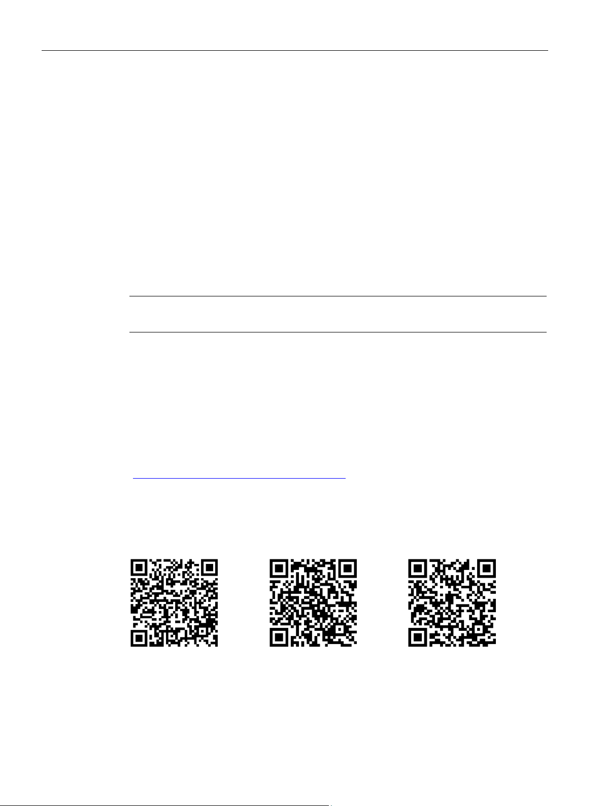
SIEMENS Industry Support App
Link for Android
Link for iOS
Link for Windows phone
1.8 DataMatrix code
A DataMatrix code is lasered onto the lower terminal cover of all devices of this series.
DataMatrix codes are standardized in ISO/IEC 16022. The DataMatrix codes on Siemens
devices use ECC200 coding.
The following device information is encoded in the DataMatrix codes as a bit stream:
● Article number
● Serial number
This information is stored in the following format in the DataMatrix code:
Data identifier Net content Separator Data identifier Net content
This machine-readable information simplifies and accelerates handling of the respective
devices.
As well as fast access to the serial numbers of the respective devices for unique
identification, the DataMatrix codes simplify communication with Siemens Technical Support.
DataMatrix codes primarily enable extremely fast and convenient access to all devicespecific information relating to an article number in the SIEMENS Service&Support Portal
(https://support.industry.siemens.com/cs/ww/en/), such as operating instructions, manuals,
data sheets, FAQs, etc.
We provide the SIEMENS Industry Support app free for this purpose and it can be used on
most commercially available smart phones and tablets.
The SIEMENS Industry Support app is available for iOS and Android-based devices and can
be accessed via the following links:
SIRIUS 3RM1 motor starter
16 Manual, 06/2016, A5E0345285095020A/RS-AE/005
Page 17

Introduction
1.9
Quick navigation
Note
Reading the manual
The quick navigation is provided to help you find important topics quickly. It does not a
substitute for reading the manual.
Always read the entire manual.
Configuring
Commissioning:
1.9 Quick navigation
● Functions (Page 32)
● Technical data (Page 139)
● Derating (temperature, installation altitude, installation) Rated operational current
(Page 57)
● Applications Operation with the EMERGENCY-STOP function (Page 83)
● Circuit diagrams (Page 159)
● Product-specific safety information (Page 19)
● Overload trip:
– Thermal calculation method (motor memory module) (Page 37)
– Setting the RESET method (Page 126)
● Terminal designations Terminals (Page 55)
● Also note the following: Number of startsNumber of starting operations (Page 144),
switching times Switching the 3RM1 motor starter under normal operating conditions
(Page 32), pausesTechnical data (Page 139), minimum current Rated operational current
(Page 57) and Minimum load current (Page 68)
● Diagnosis Alarms, faults and system events (Page 131)
● Fault rectification (Page 134)
● Terminal designation Terminals (Page 55)
● Connection method Device versions (Page 29) and Connection cross sections
(Page 141)
● Removable terminals Terminals (Page 55)
● Setting the rated operational current (Page 126)
SIRIUS 3RM1 motor starter
Manual, 06/2016, A5E0345285095020A/RS-AE/005
17
Page 18

Introduction
Service:
1.9 Quick navigation
● Diagnosis Alarms, faults and system events (Page 131)
● Setting the rated operational current (Page 126)
● Removable terminals Terminals (Page 55)
● Terminal designation Terminals (Page 55)
FAQ (https://support.industry.siemens.com/cs/ww/en/view/81525494)
SIRIUS 3RM1 motor starter
18 Manual, 06/2016, A5E0345285095020A/RS-AE/005
Page 19
2
2.1
General safety notes
DANGER
Hazardous voltage.
Will cause death or serious injury.
DANGER
Hazardous voltage.
Will cause death or serious injury.
V, screw in all terminal screws that are not
NOTICE
Damage caused by electrostatic charge
Turn off and lock out all power supplying this device before working on this device.
To ensure protection against an electric shock hazard with the hinged cover open at the
signaling contacts 95, 96, 98 at a voltage of ≥ 50
needed to clamp conductors.
When handling and installing the 3RM1 motor starters, ensure that the components are
protected from electrostatic charge. Changes to the system configuration and wiring are
only permissible in the voltage-free state.
Connection of 3RM11 / 3RM13 Failsafe motor starters is only permissible when the power
supply units (PELV and SELV) are switched off.
SIRIUS 3RM1 motor starter
Manual, 06/2016, A5E0345285095020A/RS-AE/005
19
Page 20
Product-specific safety information
2.2
Safety information for hazardous areas
WARNING
Explosion hazard in Class I and Class II Hazardous Locations.
Lebensgefahr oder schwere Verletzungsgefahr.
2.2 Safety information for hazardous areas
The components of the 3RM1 motor starters are not suitable for installation in Class I and
Class II Hazardous Locations.
The device must be installed in a control cabinet with minimum degree of protection of
IP 4x.
Please contact your ATEX specialist.
You will find further information in Chapter "ATEX-certified motor overload protection in the
case of 3RM11/3RM13 Failsafe (Page 38)."
SIRIUS 3RM1 motor starter
20 Manual, 06/2016, A5E0345285095020A/RS-AE/005
Page 21
Product-specific safety information
2.3
Safety instructions for safety-related applications
DANGER
Hazardous voltage.
Will cause death or serious injury.
WARNING
Loss of the safety function
Annual function test
WARNING
Loss of the safety function in the event of a fault in the case of 3RM11 / 3RM13 Failsafe
motor starters with 110 to 230 V AC/110 V DC control supply voltage.
Can cause death or serious injury.
WARNING
Loss of the safety function when using device connectors.
Can cause death or serious injury.
2.3 Safety instructions for safety-related applications
Turn off and lock out all power supplying this device before working on this device.
In continuous operation, the key safety values apply in the case of a function test interval
(state change of the outputs) ≤ 1 year.
• Actuate the connected sensors.
• Check their effect on the safety relay and the downstream actuators.
• Activate the safety relay via the connected sensors.
• Check their effect on the safety relay and the downstream actuators.
• Defective devices must be replaced.
The control signal for the control inputs in the case of 3RM11/3RM13 Failsafe motor
starters with 110 to 230 V AC control supply voltage must come from A1. Otherwise, the
safety function is bypassed in the event of a fault. Thus, only relay outputs are admissible
when using a PLC.
Do not use a separate control voltage. Only use the relay outputs when using a PLC.
When the product is operated with a 3SK safety relay and a device connector, the supply
voltage for 3RM1 motor starters is fed in via the device connectors.
In this case, do not connect anything to terminals A1 and A2 of the 3RM1 motor starters, in
order to prevent bypassing of the safety function.
SIRIUS 3RM1 motor starter
Manual, 06/2016, A5E0345285095020A/RS-AE/005
21
Page 22
Product-specific safety information
WARNING
Loss of the safety function during hybrid operation of Failsafe and Standard motor starters.
Can cause death or serious injury.
WARNING
Loss of the safety function when the neutral conductor is connected to a load.
Can cause death or serious injury.
NOTICE
Electromagnetic interference
Note
SILCL 3 to EN 62061:2005, PL e/Cat. 4 to EN ISO 13849-1:2008
The 3RM11 Failsafe and 3RM13 Failsafe safety
a way as to allow implementation of safety
with EN
2.3 Safety instructions for safety-related applications
Hybrid operation of 3RM10/3RM12 Standard motor starters with 3RM11/3RM13 Failsafe
motor starters in safety-related applications is not admissible.
Only ever use safety-related motor starters (3RM11 Failsafe and 3RM13 Failsafe) in safetyrelated applications.
When using the 3RM11 Failsafe and 3RM13 Failsafe motor starters, note that no neutral
conductor may be connected if the load circuit contains 3-phase loads, e.g. a 230 V brake
or resistive loads.
The following must be grounded in accordance with regulations to ensure noise immunity of
the 3RM11 / 3RM13 Failsafe motor starters:
• PELV / SELV power supply units (please also note the documentation for the respective
power supply unit in this regard).
-related motor starters are designed in such
-related applications up to SILCL 3 in accordance
62061 and PL e/Cat. 4 in accordance with EN ISO 13849-1.
SIRIUS 3RM1 motor starter
22 Manual, 06/2016, A5E0345285095020A/RS-AE/005
Page 23

Product-specific safety information
2.4
Intended use
WARNING
Improper use of hardware products.
Serious damage to property, can cause death or serious injury.
2.5
Current information about operational safety
Important note for maintaining operational safety of your system
2.4 Intended use
This equipment is only allowed to be used for the applications described in the catalog and
in the technical description, and only in conjunction with non-Siemens equipment and
components recommended by Siemens.
Correct transport, storage, installation and assembly, as well as careful operation and
maintenance, are required to ensure that the product operates safely and without faults.
EU note: Commissioning is absolutely prohibited until it has been ensured that the machine
in which the component described here is to be installed complies with the stipulations of
the Directive 2006/42/EC.
Please take note of our latest information.
Systems with safety-related characteristics are subject to special operational safety
requirements on the part of the operator. The supplier is also obliged to comply with special
product monitoring measures. For this reason, we publish a special newsletter containing
information on product developments and features that are (or could be) relevant to
operation of safety-related systems. By subscribing to the appropriate newsletter, you will
ensure that you are always up-to-date and able to make changes to your system, when
necessary:
Siemens newsletter (http://www.industry.siemens.com/newsletter)
Sign on to the following newsletter under "Products & Solutions":
● Control Components and System Engineering News
● Safety Integrated Newsletter
SIRIUS 3RM1 motor starter
Manual, 06/2016, A5E0345285095020A/RS-AE/005
23
Page 24

Product-specific safety information
2.6
Declaration of conformity
2.6 Declaration of conformity
The manufacturer declares that the safety components of the 3RM1 motor starter series in
the designs marketed by us comply with the applicable basic health and safety requirements
of the EC Directives* stated (including amendments), and that the stated standards* were
applied in their design and construction.
* You can download the complete EC Declaration of Conformity from the Internet
(http://www.siemens.com/sirius/approvals) as a PDF.
SIRIUS 3RM1 motor starter
24 Manual, 06/2016, A5E0345285095020A/RS-AE/005
Page 25
3
3.1
Overview
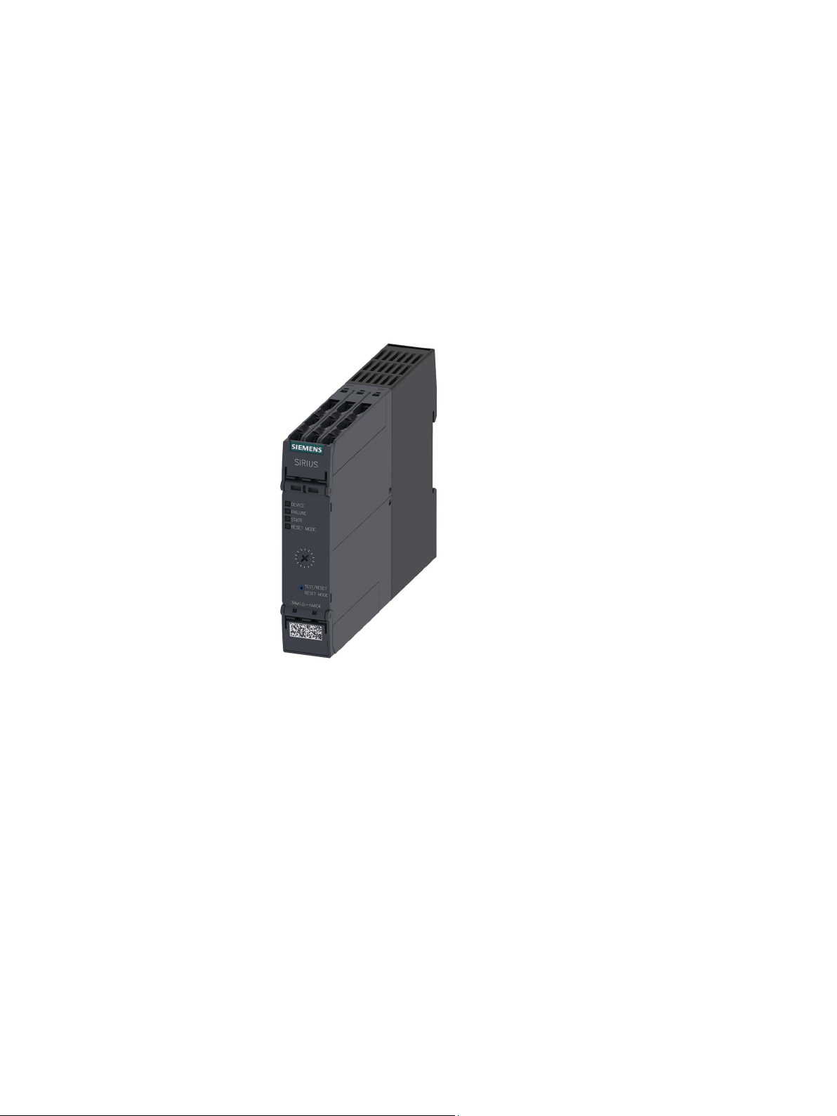
The 3RM1 motor starter is a compact device with a width of 22.5 mm. The 3RM1 motor
starter comprises combinations of relay contacts, power semiconductors, and a solid-state
overload relay for switching three-phase motors up to 3 kW (at 400 V) and resistive loads up
to 10 A (at AC voltages to 500 V) under normal operating conditions.
SIRIUS 3RM1 motor starter
Manual, 06/2016, A5E0345285095020A/RS-AE/005
25
Page 26

Description
3.2
Applications
3.2 Applications
The 3RM1 motor starters can be used wherever combinations of contactors and overload
relays were previously used.
Thanks to the additional functionality of safety-related shutdown, the 3RM11 Failsafe and
3RM13 Failsafe motor starter variants are ideally suited to safety-related applications up to
SILCL 3 in accordance with EN 62061 and PL e/Cat. 4 in accordance with EN ISO 13849-1.
Short-circuit protection in a load feeder designed in this way must be implemented by
appropriate upstream short-circuit protection devices. These can be, for example, circuit
breakers or appropriate fuses.
You achieve maximum space-savings benefits by means of a group configuration of the
3RM1 motor starters. This enables several 3RM1 motor starters to be protected by one
short-circuit protection device.
The 3RM1 motor starters are used in the following areas, for example:
● Conveyor technology
● Logistics systems
● Production machines
● Machine tools
● Small elevators
SIRIUS 3RM1 motor starter
26 Manual, 06/2016, A5E0345285095020A/RS-AE/005
Page 27

Description
3.3
Hybrid technology
Switching on
Current conducting
Switching off
3.3 Hybrid technology
The 3RM1 motor starter combines the benefits of semiconductor technology and relay
technology.
This combination is known as hybrid technology. The hybrid technology in the 3RM1 motor
starter is characterized by the following features:
The inrush current in the case of motorized loads is conducted briefly via the
semiconductors.
Advantage: The relay contacts are protected. Longer service life is achieved thanks to
reduced wear and tear.
The continuous current is conducted via relay contacts.
Advantage: Relay contacts cause less thermal losses than semiconductors.
Switch-off is implemented again via the semiconductor.
Advantage: The contacts are only slightly burdened by arcs. This results in increased service
life.
SIRIUS 3RM1 motor starter
Manual, 06/2016, A5E0345285095020A/RS-AE/005
27
Page 28
Description
Circuit diagram
3.3 Hybrid technology
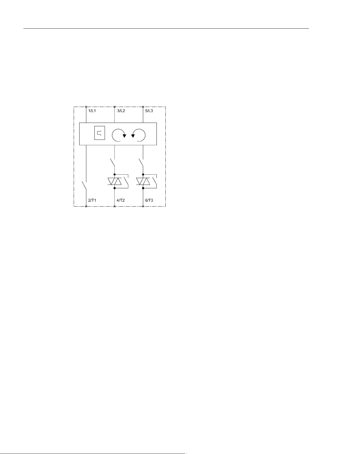
The semiconductors switch the motor on and off in two phases. In the switched-off state, all
three phases are opened by a relay contact.
To achieve the highest safety level SILCL 3 in accordance with EN 62061, PL e/Cat. 4 in
accordance with EN ISO 13849-1 in the case of 3RM11/3RM13 fail-safe motor starters,
further relay contacts are installed in series with the semiconductors.
Figure 3-1 Circuit diagram
SIRIUS 3RM1 motor starter
28 Manual, 06/2016, A5E0345285095020A/RS-AE/005
Page 29
Description
3.4
Device versions
Feature
3RM10
3RM11
3RM12
3RM13
Direct-on-line starter
✓ ✓ -
-
Reversing starter
- - ✓
✓
ATEX certification overload protection
- ✓ -
✓
EN ISO 13849-1
Connection systems
3.4 Device versions
The 3RM1 motor starters are characterized by their compact design and narrow width.
They can be used for easy assembly of fuseless load feeders with SIRIUS motor starter
protectors. Alternatively, combinations with fuses or other short-circuit protection devices are
possible.
This allows implementation of load feeders with coordination type 1 for short-circuit currents
of up to 55 kA at 400 V.
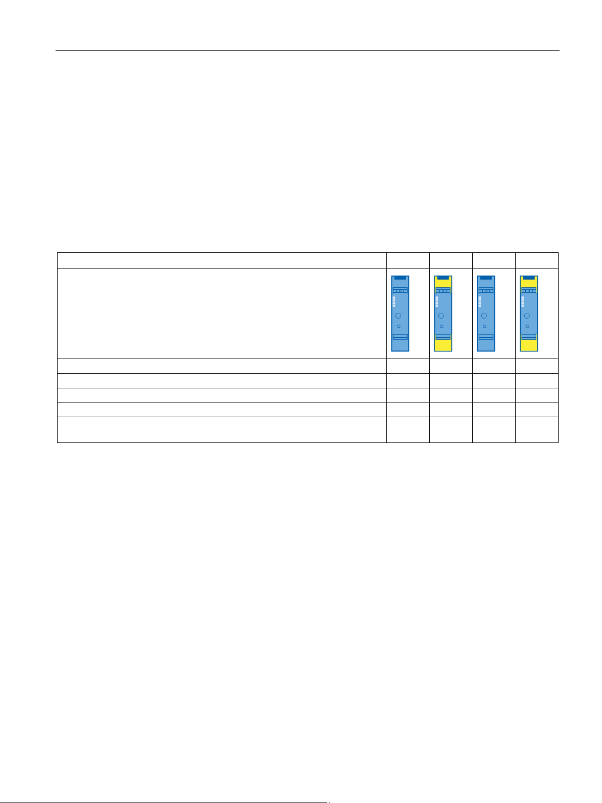
The 3RM1 motor starters are available in four different versions:
Table 3- 1 Motor starter version
Product symbol
Overload protection with wide setting range ✓ ✓ ✓ ✓
Safety-related shutdown up to SILCL 3 to EN 62061, PL e/Cat. 4 to
- ✓ - ✓
The 3RM1 motor starters are optionally available with screw connections or push-in
connections.
Push-in connections are a form of spring-loaded terminals allowing fast wiring without tools
for rigid conductors or conductors equipped with end sleeves. For wiring finely-stranded or
stranded conductors without end sleeves on push-in connections, a screwdriver (with
3.0 x 0.5 mm blade) is required. A screwdriver (with 3.0 x 0.5 mm blade) is also required to
disconnect a conductor.
The advantages of the push-in terminals are found, as with all spring-loaded terminals, in
speed of assembly and disassembly and vibration-proof connection. There is no need for the
checking and tightening required with screw connections.
SIRIUS 3RM1 motor starter
Manual, 06/2016, A5E0345285095020A/RS-AE/005
29
Page 30

Description
Current ranges
Versions
Adjustable response value current
[A]
Maximum permissible motor power
at 400 V AC [kW]
3RM1.01-.....
0.1 ... 0.5
0.12
3RM1.07-.....*
1.6 ... 7
3
* The versions of the 3RM1.07
heaters) up to a rated operational current of I
AC51
= 10 A.
Control supply voltages
Versions
Control supply voltage
3RM1...-.AA0.
24 V DC
3RM1...-.AA1.
110 … 230 V AC 50/60 Hz; 110 V DC
Note
Motor starters with 24 V DC control supply voltage
As is usual on solid
24
specifically shut down
disconnection of the control supply voltage. As a result, charging currents can arise briefly
upon activation of the control supply voltage. The buffering capacitance is decoupled by a
diode. Thi
You can find more information on the Internet
(
Note
3RM10/3RM12
with 24 V DC control supply voltage
The same voltage source (potential) must be used for the control supply voltage and the
control inputs.
The reference point for the control
3.4 Device versions
The 3RM1 motor starters are designed for the following rated operational currents of the
loads:
Table 3- 2 Current ranges
3RM1.02-..... 0.4 ... 2 0.75
-..... motor starter are also suitable for operating resistive loads (e.g.
The 3RM1 motor starters are designed for the following control supply voltages:
Table 3- 3 Control supply voltages
Note the following information for the different device versions:
-state motor starters, a buffering capacitance of 250 µF is installed in the
V DC control circuit of the 3RM1 Standard and Failsafe motor starters. Its purpose is to
the motor with the semiconductors in the event of failure or
s means that there is no influence on the dark test of safety-related outputs.
https://support.industry.siemens.com/cs/ww/en/view/91372998).
Standard motor starters
inputs is terminal A2.
SIRIUS 3RM1 motor starter
30 Manual, 06/2016, A5E0345285095020A/RS-AE/005
Page 31

Description
Note
3RM10/3RM12 Standard motor starters with 110 to 230 V AC/110 V DC control supply
voltage
The same voltage source (potential) must be used for the control supply voltage and the
control inputs.
The reference point for the
When controlling with a PLC, control must be via relay outputs.
There must be no parallel load (e.g. a lamp) connected at the control inputs in the case of
motor starters with the product version E01.
Note
3RM11/3RM13 Failsafe motor starters with 24 V DC control supply voltage
The control inputs are electrically isolated from the control supply voltage (A1, A2).
The terminals M1 and M2 are the reference point for the control inputs.
For controlling the control inputs, e.
SELV/PELV Class 2 supply is required.
Note
3RM11/3RM13 Failsafe motor starters with 110 to 230 V AC/110 V DC control supply
voltage
The same voltage source (potential) must be used for the contro
control inputs in safety
The reference point for the control inputs is terminal A2.
When controlling with a PLC, control must be via relay outputs.
3.4 Device versions
control inputs is terminal A2.
g. via the digital outputs of a PLC, a voltage from an
l supply voltage and the
-related applications.
SIRIUS 3RM1 motor starter
Manual, 06/2016, A5E0345285095020A/RS-AE/005
31
Page 32

Description
3.5
Functions
3.5.1
Switching the 3RM1 motor starter under normal operating conditions
Version
Article number
Pause time
Note
Minimum loads must be observe
You will find additional information in the chapter "
NOTICE
Damage to property due to high making currents
NOTICE
Damage during operation on non-sinusoidal voltages
3.5 Functions
A typical application area of the 3RM1 motor starter is the switching and protection of
motors. You can also operate the 3RM1 motor starter on resistive loads such as heaters.
During operational switching of the 3RM1 motor starter, an auto pause kicks in after the
motor has been switched off. The motor starter does not accept a new start until the pause
time has elapsed.
Table 3- 4 Pause time of 3RM1 motor starters
Standard 3RM10..-….;
3RM12..-….
Fail-safe 3RM11..-….;
3RM13..-….
• 500 ms (E01)
• 100 ms (E02)
• 500 ms (E01)
No distinction is made between direct-on-line and reversing starters in terms of pause time.
d for the 3RM1 motor starters.
Minimum load current (Page 68)".
When using capacitive loads, the switching components in the 3RM1 motor starter can be
damaged by excessively high making currents.
Do not operate capacitive loads such as frequency converters on the 3RM1 motor starter.
Operation of single-phase capacitor motors is admissible.
When operating frequency converters, the switching components in the 3RM1 motor starter
can be damaged by non-sinusoidal voltages.
Do not operate the 3RM1 motor starter on outputs of frequency converters.
SIRIUS 3RM1 motor starter
32 Manual, 06/2016, A5E0345285095020A/RS-AE/005
Page 33
Description
NOTICE
Damage to property
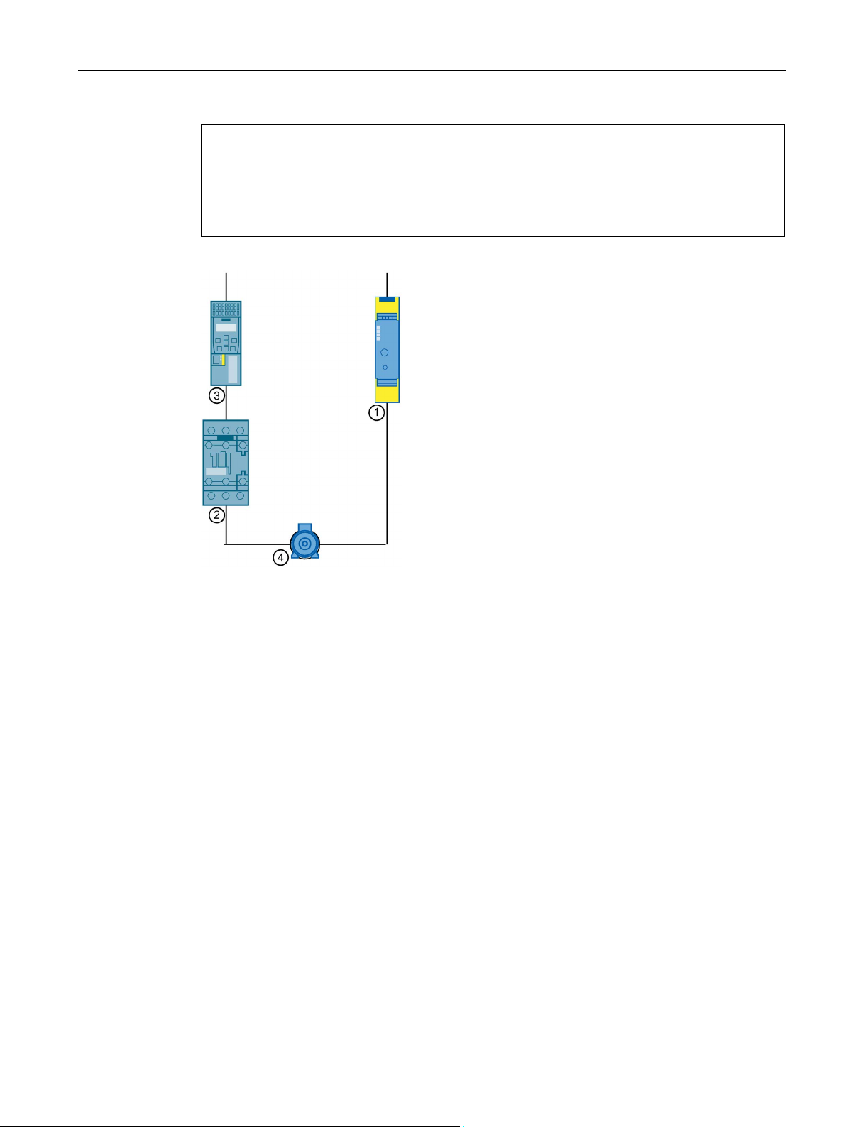
①
SIRIUS 3RM13 Failsafe motor starter
②
SIRIUS 3RT2 contactor
③
Frequency converter, e.g. SINAMICS G120 frame size A with BOB-2, 2nd generation
④
Motor
3.5.1.1
Direct-on-line starter
Using the 3RM1 motor starter as a direct-on-line starter
3.5 Functions
If you are operating a 3RM1 motor starter in parallel to a frequency converter on the same
motor, install an isolating contactor. If the frequency converter has an output filter, the
isolating contactor must be installed downstream of this filter.
Figure 3-2 3RM13 as an alternative control to a frequency converter
All 3RM1 motor starters can be used as direct-on-line starters.
To switch the 3RM1 motor starter on, apply the control voltage at input IN1.
After the motor is switched off, the motor starter accepts a new start after a pause time.
You can also use the versions of the 3RM1 motor starter with a rated operational current up
to 7 A for switching resistive loads up to I
AC51
= 10 A under normal operating conditions.
SIRIUS 3RM1 motor starter
Manual, 06/2016, A5E0345285095020A/RS-AE/005
33
Page 34
Description
3.5.1.2
Reversing starter
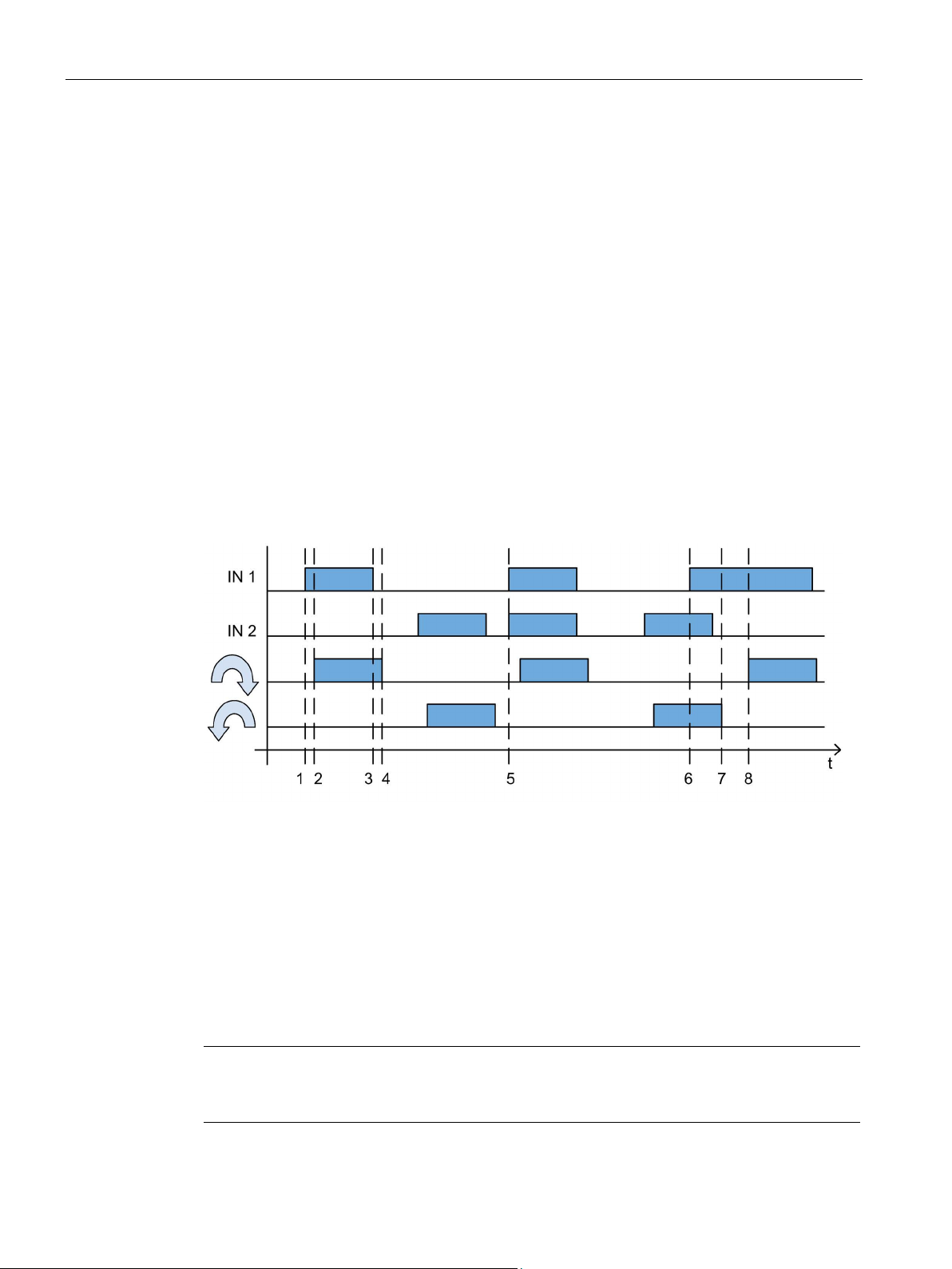
Using the 3RM1 motor starter as a reversing starter
Interlocking of the control inputs
1
Controller 1 active
2
Motor ON
1-2
Switch-on delay
3
Control input 1 inactive
4
Motor OFF
3-4
Switch-off delay
direction.
6
Additional activation of the second control input has no influence.
7-8
After motor OFF, the motor starter accepts a new start (motor ON) after a pause time.
Note
Please observe the information about the control supply voltage and the control inputs in the
chapter "
3.5 Functions
The 3RM12 and 3RM13 motor starters can be used as reversing starters.
The reversing starter starts the motor when the control voltage is applied at input IN1 in
direction of rotation 1 (no phase swapping), when controlling input IN2 in direction of
rotation 2 (phase change from L1 and L3).
After the motor is switched off, the motor starter accepts a new start after a pause time.
If you apply control inputs IN1 and IN2 simultaneously, control input IN1 has priority. The
motor starts up in this direction of rotation.
When the motor is running, activation of the second input has no effect.
The figure below shows an example of the effects of the signals at the control inputs on the
direction of rotation of the motor:
5 With simultaneous activation of the control inputs, the motor is started in the clockwise
Device versions (Page 29)".
SIRIUS 3RM1 motor starter
34 Manual, 06/2016, A5E0345285095020A/RS-AE/005
Page 35
Description
3.5.2
Protective functions
3.5.2.1
Overload protection
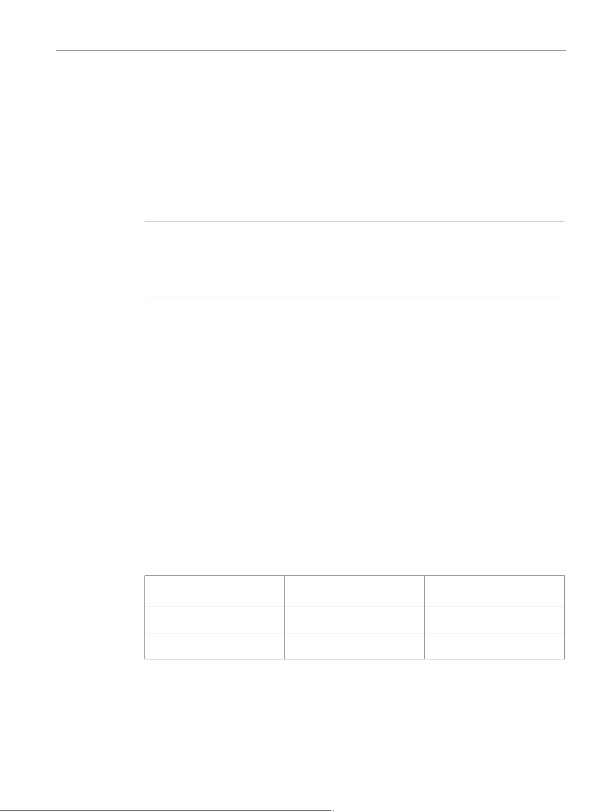
Note
ATEX-certified motor overload protection in the case of 3RM11/3RM13 Failsafe
Overload
ATEX
case of 3RM11/3RM13 Failsaf
3.5.2.2
Equipment protection
3.5.2.3
Phase failure protection
Standard motor starters
3RM10/3RM12
Failsafe motor starters
3RM11/3RM13
command
after 5 s.
switch on.
state
after 5 s.
after 5 s.
3.5 Functions
The 3RM1 motor starter protects three-phase motors against overload. If the current
exceeds the set value, the 3RM1 motor starter switches off within the specified tripping time
and signals the fault via the LEDs and the fault signaling output. You will find the tripping
characteristic in the chapter "Overload protection/device protection characteristic
(Page 145)".
protection of safety-related 3RM11 Failsafe and 3RM13 Failsafe motor starters is
-certified up to SILCL 2; see Chapter "ATEX-certified motor overload protection in the
e (Page 38)."
In addition to the motor protection function, the 3RM1 motor starters also protect themselves
against overload. This means that in the case of 3RM1 motor starters with a rated
operational current of 7 A, an overload trip may occur in the upper current range before the
motor protection trips.
If, for example, 8-fold current flows in the case of an unloaded motor memory module and a
set current of 7 A, tripping takes place after approximately one second.
You will find the tripping characteristic in the chapter "Overload protection/device protection
characteristic (Page 145)".
The 3RM1 motor starter is provided with phase failure protection to prevent excessive
temperature rise in the load in double phasing if phase failure occurs.
Depending on whether the phase failure already occurs before the ON command or during
the ON state, the devices respond as described in the table and signal a phase failure.
Phase failure before the ON
Phase failure during the ON
The motor starter switches off
The motor starter switches off
The motor starter does not
The motor starter switches off
SIRIUS 3RM1 motor starter
Manual, 06/2016, A5E0345285095020A/RS-AE/005
35
Page 36

Description
NOTICE
Damage due to asymmetrical current consumption by built-in brakes
An additional braking device can only be installed for Standard 3RM1 motor starters:
this kind.
NOTICE
Damage from incorrect connection
3.5.2.4
Asymmetry monitoring
3.5 Functions
The fault state is indicated by LEDs and the fault signaling output.
When connecting and operating motors with built-in brakes, the energy for releasing the
brakes is taken from the motor connection cables. This can result in substantial asymmetry
in power consumption.
The following applies to 3RM1 Standard and Failsafe motor starters:
• If the current for the braking device is taken from two phases, connect the motor cables
that are additionally loaded with braking current to terminals T1 and T3. Observe the
additional braking current when setting the motor current.
• Alternatively, the braking device can be fed externally.
• If the current for the braking device is taken from just one phase and the neutral
conductor, connect the motor cable that is loaded with the braking current to terminal T2
of the motor starter.
Do not use 3RM11 Failsafe and 3RM13 Failsafe motor starters for braking devices of
Incorrect connection of the motor can result in damage.
Connect the motor as specified in the typical circuit diagrams.
You can find circuit diagrams for operating motors with brakes in the chapter "Typical circuits
(Page 167)".
Asymmetry detection will only work if all three phases are directly dependent upon one
another, i.e. when no external current flow is possible.
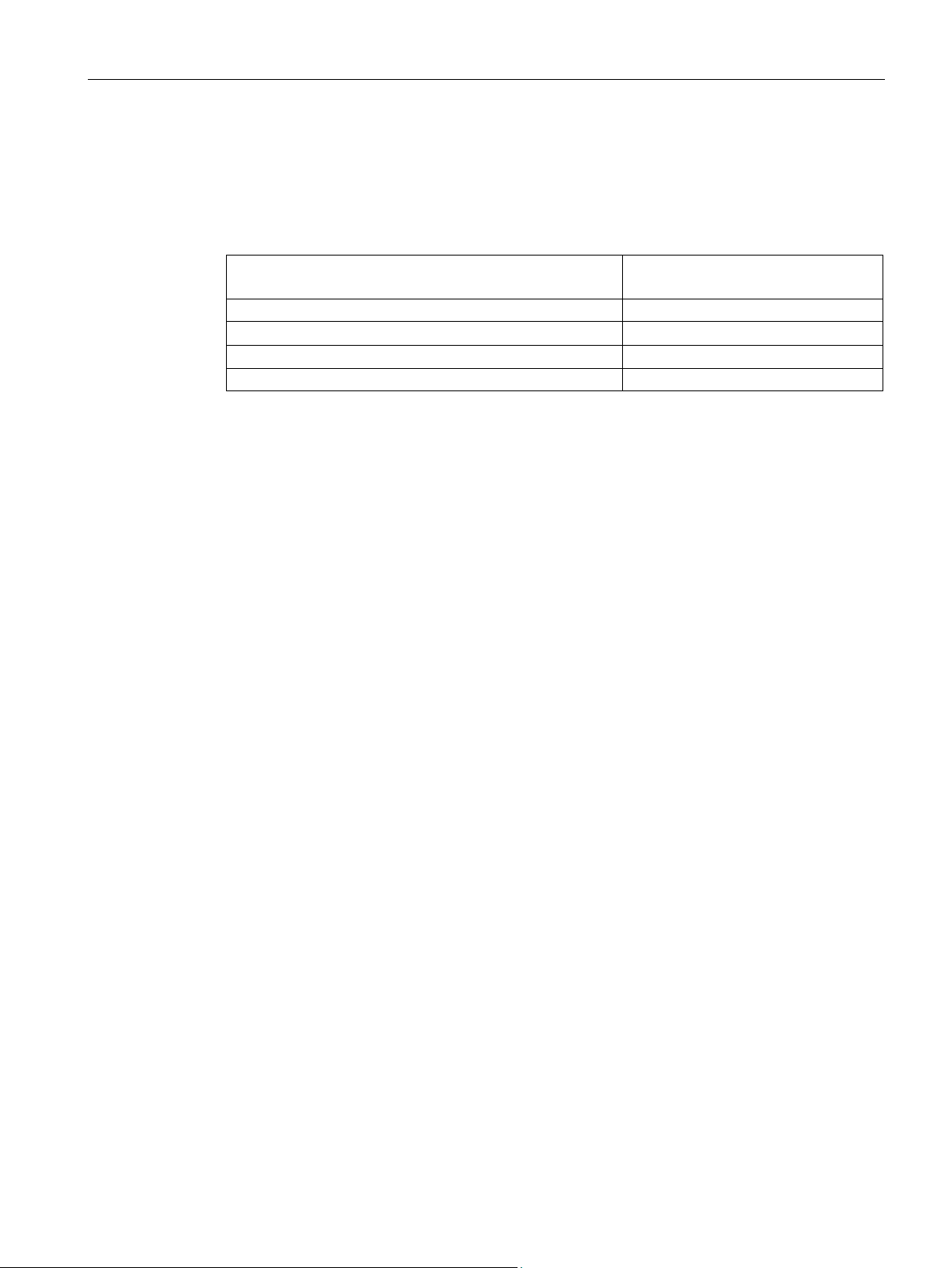
Asymmetry is detected as soon as one of the three phases deviates by more than 40 % from
the mean value of all phases. As soon as this happens, the 2-pole trip curve CLASS 10 A is
applied (see Chapter "Overload protection/device protection characteristic (Page 145)"). This
means: The function trips as soon as a minimum value of 85.5 % of the set rated current is
reached. If the current is below 85.5 % of the set rated current in all three phases, the
function will not trip. For values above 85.5 % of the set current, the higher the current, the
faster the function will trip.
SIRIUS 3RM1 motor starter
36 Manual, 06/2016, A5E0345285095020A/RS-AE/005
Page 37
Description
Maximum current in one of the 3 phases with reference to
the set rated current [%]
Tripping time [s]
86
132
100
50
120
32
3.5.2.5
Thermal calculation method (motor memory module)
Principle of operation
3.5 Functions
For exact values, see the curve in Chapter "Overload protection/device protection
characteristic (Page 145)." Some values are provided as examples from this curve in the
table.
Table 3- 5 Tripping times for tripping due to detected asymmetry
90 77
The asymmetry detection is not active for setting value 10 A for resistive loads; in this case
the overload trip occurs according to the table Table 9-1 Tripping for resistive loads at a
setting value of 10 A (Page 147)
The electronics continuously calculate a model of the thermal load on the motor dependent
on the operating time and the current load. The motor memory module charges when the
motor is switched on. The motor memory module discharges after the motor is switched off.
Following an overload tripping operation, the motor memory module is fully discharged after
approximately three minutes. You must wait for this cooling time to elapse before you can
acknowledge the fault. If the control supply voltage fails, the 3RM1 motor starter stores the
remaining cooling time. When the control supply voltage is restored, the remaining cooling
time elapses before the motor can be switched on again.
If you initiate a restart within a very short time after switching off the motor, it may be that the
motor memory module has not yet fully discharged. This can result in an extremely fast
overload trip after the restart. During continuous operation ("Warm" motor memory module),
tripping times are reduced depending on the prior load.
If voltage is present at terminals A1/A2 and at control inputs IN1/IN2 after resetting the
overload trip, the 3RM1 motor starter restarts.
The rated current of 10 A must not be set for motorized loads but only for resistive loads. In
this setting, the tripping characteristics deviate from Class 10A; see Chapter "Overload
protection/device protection characteristic (Page 145)".
SIRIUS 3RM1 motor starter
Manual, 06/2016, A5E0345285095020A/RS-AE/005
37
Page 38
Description
WARNING
Automatic restart following Reset.
Can cause death or serious injury.
Reset in manual operation
Note
If you briefly switch the control supply voltage off and on again, there is no automatic
acknowledgment.
3.5.2.6
ATEX-certified motor overload protection in the case of 3RM11/3RM13 Failsafe
Standards
EN 60079-14 / VDE 0165-1
EN 60079-17
EN 50495
3.5 Functions
You can find information about typical switching frequencies in Chapter "Number of starting
operations (Page 144)".
If the DEVICE LED shows a yellow light and the FAILURE LED a red light, and a manual
RESET or auto RESET takes place following an overload trip, the machine starts up
immediately if there is a control command at IN1/IN2. Personnel in the danger area can be
injured.
Make sure that the danger area of the machine is kept clear of people.
If the RESET method is set to manual RESET, acknowledge an overload trip as follows:
1. Wait for the cooling time to elapse.
2. Press the "TEST/RESET/RESET MODE" button to acknowledge.
As an alternative, in the case of the 3RM10/3RM12 Standard motor starters, you can use
the RESET control input IN3 for acknowledgment.
Increased danger in hazardous areas means it is necessary to carefully observe the
following standards:
●
●
●
Inspection and maintenance of electrical installations in hazardous areas.
Safety devices required for the safe functioning of equipment with respect to
explosion risks.
Electrical apparatus for explosive gas atmospheres.
SIRIUS 3RM1 motor starter
38 Manual, 06/2016, A5E0345285095020A/RS-AE/005
Page 39
Description
Certification of 3RM11/3RM13 Failsafe motor starters
overpressure encapsulation systems.
WARNING
Improper handling.
Can cause death, serious injury, or damage to property.
Control cabinet degree of protection in hazardous areas
DANGER
Explosion hazard in Class I and Class II Hazardous Locations.
Can cause death or serious injury.
3.5 Functions
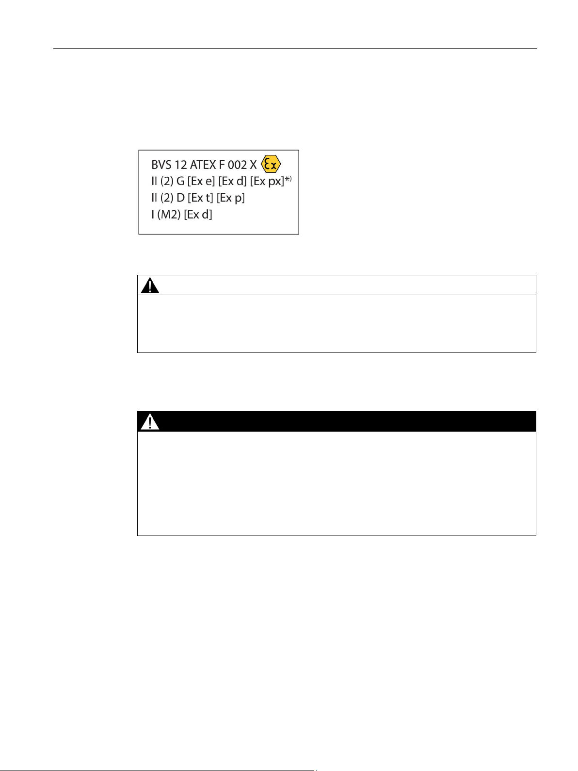
The 3RM11 Failsafe and 3RM13 Failsafe motor starters are approved under Device
Group II, Category (2) in the area "GD" (areas in which explosive gas, steam, mist, air
mixtures and combustible dust are present):
)
*
For the px applications, pressure and flow rate monitoring are additionally required for the
All work involved in connecting, commissioning and maintenance must be carried out by
qualified personnel.
The components of the 3RM1 motor starters are not suitable for installation in Class I and
Class II Hazardous Locations.
The device must be installed in a control cabinet with minimum degree of protection of
IP 4x.
Please contact your ATEX specialist.
In addition to the motor protection function, the 3RM1 motor starters also protect themselves
against overload. This means that in the case of 3RM1 motor starters with a rated
operational current of 7 A, an overload trip may occur in the upper current range before the
motor protection trips.
If, for example, 8-fold current flows in the case of an unloaded motor memory module and a
set current of 7 A, tripping takes place after approximately one second.
You will find the tripping characteristic in the chapter "Overload protection/device protection
characteristic (Page 145)".
SIRIUS 3RM1 motor starter
Manual, 06/2016, A5E0345285095020A/RS-AE/005
39
Page 40

Description
Setting the rated motor operational current
Note
Observe the trip class or the tripping characteristic of the 3RM1 motor starter in Chapter
"
must be designed for the selected trip class.
RESET settings
Note
Restriction in the hazardous area
In applications for the protection of motors in hazardous a
motor starter may only be operated with the "Manual RESET" setting. The "RESET Mode"
LED must be off.
Short-circuit protection
Cable protection
Cyclic test of the protection functions
Ambient conditions
3.5 Functions
Set the 3RM1 motor starter to the rated motor operational current (according to the type
plate or design test certificate of the motor).
On this topic, refer to the Chapter "Setting the rated operational current (Page 126)".
Overload protection/device protection characteristic (Page 145)". The motor and cables
reas, a 3RM11/3RM13 Failsafe
Short-circuit protection must be handled by separately arranged overcurrent protection
devices.
On this topic, refer to the Chapter "Load feeders - protection against short circuit (Page 69)".
Avoid impermissibly high cable surface temperatures by correctly dimensioning the cross
sections. Select an adequate cable cross-section.
The tests are run by means of the "TEST/RESET/RESET MODE" button and can take place
when the motor is either on or off. The test consists of three function tests.
Carry out the tests during commissioning
You will find out how to run the test in Chapter "Carrying out the function test (Page 45)".
and cyclically every 36 months at the latest.
See the chapter "Ambient conditions (Page 63)".
SIRIUS 3RM1 motor starter
40 Manual, 06/2016, A5E0345285095020A/RS-AE/005
Page 41

Description
ATEX-specific safety data
Safety integrity level (SILCL)
2
Hardware fault tolerance (HFT)
0
Interval for testing the protective functions
3 years
Probability of failure on demand (PFD)
5x10⁻⁴
Note
See the data sheet for other specifications. You will find the data sheet in Service&Support
(
Maintenance and repairs
Note
Repairs to the device may only be carried out by the manufacturer.
Warranty
NOTICE
Further information
3.5 Functions
The motor protection function according to ATEX in the case of 3RM11/3RM13 motor
starters has the following safety data:
Probability of a dangerous failure per hour (PFH) 5x10⁻⁸ 1/h
https://support.industry.siemens.com/cs/ww/en/ps/16311/td).
These devices are maintenance-free.
To meet the conditions of the warranty, you must observe the safety and commissioning
instructions.
You will find further information on the Internet at
● Internet (http://www.siemens.com/sirius)
● Information and Download Center (http://www.siemens.com/sirius/infomaterial)
● Product Support (http://www.siemens.com/sirius/support)
● Service and Support (http://www.siemens.com/sirius/technical-assistance)
● Certificates (http://www.siemens.com/sirius/approvals)
SIRIUS 3RM1 motor starter
Manual, 06/2016, A5E0345285095020A/RS-AE/005
41
Page 42
Description
3.5.3
Shutdown on malfunction
Shutdown via integrated monitoring
Monitoring before switching on in the case of 3RM11/3RM13 Failsafe motor starters
Acknowledging
WARNING
Loss of the safety function.
Can cause death or serious injury.
Note
If a malfunction is repeatedly indicated, the 3RM1 motor
replaced.
Safety-related shutdown in the case of 3RM11/3RM13 Failsafe motor starters
3.5 Functions
The 3RM1 motor starter has integrated monitoring of the main circuit components. During
operation, the 3RM1 motor starter detects when a switching element fails to switch, or when
a phase has failed.
In the case of the 3RM11 Failsafe and 3RM13 Failsafe motor starters, monitoring prevents
the load from switching on in the case of the following malfunctions:
● Damage to the power semiconductors
● Damage to the relay contacts
● Faults in the control electronics
A malfunction is acknowledged by switching the control supply voltage back on and then
pressing the "TEST/RESET/RESET MODE" pushbutton.
Check the safety function after acknowledging a disruption in the case of 3RM11/3RM13
Failsafe motor starters.
starter is defective and must be
Safety-related shutdown is achieved for the 3RM11 Failsafe and 3RM13 Failsafe motor
starters thanks to the special arrangement and checking of the switching elements. Safetyrelated shutdown takes place when the control supply voltage is deactivated or by switching
off the control inputs. Malfunctions result in automatic shutdown. You will find further
information in Chapter "Safety-related shutdown with 3RM11/3RM13 Failsafe motor starters
(Page 43)."
SIRIUS 3RM1 motor starter
42 Manual, 06/2016, A5E0345285095020A/RS-AE/005
Page 43
Description
Display concept
3.5.4
Safety-related shutdown with 3RM11/3RM13 Failsafe motor starters
General description
WARNING
Loss of the safety function during hybrid operation of Failsafe and Standard motor starters.
Can cause death or serious injury.
Note
Fault signaling output (95-96-98) behavior in the event of safety-related shutdown
The fault signaling output (95
shutdown via the control supply voltage. If the fault is still present after reconnection of the
control supply voltage, the fault signaling u
detected before shutdown, the remaining cooling time is saved and elapses after
reconnection of the control supply voltage.
3.5 Functions
The following events indicate the "Malfunction" status:
● DEVICE LED flashes red
● FAILURE LED shows a red light
● Fault signaling output active
In the case of 3RM11 / 3RM13 Failsafe motor starters, safety-related shutdown is achieved
by removal of the control voltage (A1 / A2). As an alternative in the case of units with a 24 V
DC supply voltage, safety-related shutdown can be performed by canceling the ON
command (IN1/IN2).
SILCL 3 to EN 62061, PL e/Cat. 4 to EN ISO 13849-1 can be achieved with both shutdown
methods. To achieve SILCL 3/PL e/Cat. 4 for the safety function, all components of the
safety function (detecting/evaluating/reacting) must be designed accordingly.
In the case of 3RM11/3RM13 Failsafe motor starters, the OFF state is defined as the safe
state. 3RM11/3RM13 Failsafe motor starters are self-monitoring in compliance with SILCL
3/PL e and therefore do not need to be monitored in the feedback circuit of the upstream
evaluation unit/control.
Hybrid operation of 3RM10/3RM12 Standard motor starters with 3RM11/3RM13 Failsafe
motor starters in safety-related applications is not admissible.
Only ever use safety-related motor starters (3RM11 Failsafe and 3RM13 Failsafe) in safetyrelated applications.
-96-98) resumes its original state in the event of safety-related
nit becomes active again. If an overload was
SIRIUS 3RM1 motor starter
Manual, 06/2016, A5E0345285095020A/RS-AE/005
43
Page 44
Description
3.5.4.1
Safety-related shutdown via the control supply voltage
Direct link to the 3SK safety relay
WARNING
Loss of the safety function when using device connectors.
Can cause death or serious injury.
Note
The device connector can only be used in combination with motor starters that have a 24
V
Wire connection to a safe output
3.5 Functions
To ensure safety-related shutdown via the control supply voltage, you can directly connect
up to 5 motor starters to the 3SK safety relay via the device connector. In this case, the 24 V
DC control supply voltage is supplied via the device connector. In a safety case, the
3RM11/3RM13 Failsafe motor starters will be shut down by removal of the control supply
voltage by the 3SK safety relay. No additional wiring is required between the 3SK safety
relay and the 3RM1 motor starter. Nothing may be connected to terminals A1 and A2 of the
3RM1 motor starters.
When operating with a 3SK safety relay and a device connector, the supply voltage for
3RM1 motor starters is established via the device connectors.
In this case, do not connect anything to terminals A1 and A2 of the 3RM1 motor starters, in
order to prevent bypassing of the safety function.
DC supply voltage.
Shutdown of the 3RM11 / 3RM13 Failsafe motor starter by removal of the control supply
voltage can also be performed by wiring to a safe output of a fail-safe control / evaluation
unit. This method can be used to shut down a single motor starter or a group of up to 5
motor starters safely. For safe group shutdown, the 3RM11 / 3RM13 Failsafe motor starters
are connected to each other via the device connector. In this case, the control supply voltage
is wired from the safe output to the first motor starter in the group.
SIRIUS 3RM1 motor starter
44 Manual, 06/2016, A5E0345285095020A/RS-AE/005
Page 45

Description
Note
Motor starters with 24 V DC control supply voltage
As is usual on
24
specifically shut down the motor with the semiconductors in the event of failure o
disconnection of the control supply voltage. As a result, charging currents can arise briefly
upon activation of the control supply voltage. The buffering capacitance is decoupled by a
diode. This means that there is no influence on the dark test of safe
You can find more information on the Internet
(
Safety-related shutdown via inputs IN1 and IN2
3.5.5
Carrying out the function test
3.5 Functions
If it can be ensured that the cables are installed in such way that they are protected against a
cross-circuit and short-circuit to a power cable, safety-related shutdown of A1 (I+) via a
safety-related output of the control will suffice. If this cannot be ensured, or if a PM-switching
output is used, both A1 (L+) and A2 (M) must be shut down via a safety-related output. In
both cases, safety-related shutdown in compliance with SILCL 3 per EN 62061, PL e / Cat. 4
per EN ISO 13849-1 is achieved.
solid-state motor starters, a buffering capacitance of 250 µF is installed in the
V DC control circuit of the 3RM1 Standard and Failsafe motor starters. Its purpose is to
r
ty-related outputs.
https://support.industry.siemens.com/cs/ww/en/view/91372998).
As an alternative in the case of 3RM11 / 3RM13 Failsafe motor starters with a 24 V DC
supply voltage, safety-related shutdown via the IN1 and IN2 inputs is possible. The safetyrelated output of the fail-safe control / evaluation unit performs operational switching.
Depending on peripherals used, shutdown is in one or two channels:
● PM (PPM)-switching: shutdown is in two channels.
● PP-switching: shutdown is in one channel.
Single-channel switching achieves SILCL 3 per EN 62061, PL e/Cat. 4 per EN ISO
13849-1 if steps are taken to ensure that the cables are installed in such a way that they
are protected against a cross-circuit/line-to-line fault.
You can start the different individual tests for the function test with the
"TEST/RESET/RESET MODE" button.
SIRIUS 3RM1 motor starter
Manual, 06/2016, A5E0345285095020A/RS-AE/005
45
Page 46

Description
Procedure
Actuation time for
starting the test
Explanation
LED-Test
All four LEDs are activated.1)
Current measuring test
Motor protection test disconnection
without a cooling time by pressing the "TEST/RESET/RESET MODE" pushbutton again.
1)
unchanged.
Actuation time for
starting the test
Status
OK
Fault
LED test
"DEVICE" LED
Shows a yellow light1)
Off
"FAILURE" LED
Shows a red light1)
Off
"STATE" LED
Shows a green light1)
Off
"RESET MODE" button
Shows a green light1)
Off
Current measuring test
Motor protection trip test
"DEVICE" LED
Shows a yellow light
Flashing red
"FAILURE" LED
Shows a red light
Shows a red light
Fault signaling output
Active
Not active
Switching elements/motor
Deactivated
Unchanged
1)
unchanged.
Note
If the 3RM1 motor starter does not respond as in the table above during the function test,
check the connections and the supply to the 3RM1 motor starter. If the fault persists after
correct disconnection, the device must be replaced.
3.5 Functions
Depending on how long the "TEST/RESET/RESET MODE" button is pushed, a specific test
is started:
< 2 s
2 s ... 5 s
Current measuring is tested in all 3 phases.
> > 5 s
The entire control chain is tested, including the switching elements and the fault signaling output.
If the device responds as standard, an overload trip takes place. This can be reset immediately
Exception in the case of 3RM11/3RM13 Failsafe motor starters: in the case of 3RM11/3RM13 Failsafe motor starters,
the LED test is only carried out in the OFF state (without load current). In the ON state (with load current), the LEDs stay
< 2 s
2 s ... 5 s "DEVICE" LED
• Without load current: Flickering red
• With load current: Flashing red
> 5 s
Exception in the case of 3RM11/3RM13 Failsafe motor starters: in the case of 3RM11/3RM13 Failsafe motor starters,
the LED test is only carried out in the OFF state (without load current). In the ON state (with load current), the LEDs stay
SIRIUS 3RM1 motor starter
46 Manual, 06/2016, A5E0345285095020A/RS-AE/005
Off
Page 47
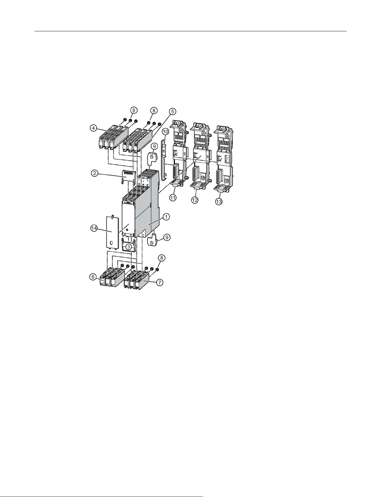
Description
3.6
Accessories and article number scheme
3.6.1
Overview of all device components
①
Basic unit/expansion unit, e.g. 3RM1 motor starter
②
Top cover flap
③
Bottom cover flap
④
Terminals, 3-pole, push-in, 1 x 2.5 mm²
⑤
Terminals, 3-pole, screw-type, 1 x 2.5 mm²
⑥
Terminals, 3-pole, push-in, 1 x 4 mm²
⑦
terminals.
⑧
Coding pins
⑨
Push-in lugs for wall mounting
⑩
Cover
⑪
Device connector
⑫
Device connector
⑬
Device termination connector
⑭
Sealable cover
3.6 Accessories and article number scheme
Terminals, 3-pole, screw-type, 1 x 4 mm²
For connection, there is an infeed system (not shown in the overview diagram) for these
SIRIUS 3RM1 motor starter
Manual, 06/2016, A5E0345285095020A/RS-AE/005
47
Page 48

Description
3.6.2
Accessories
3.6.2.1
Infeed system
3.6 Accessories and article number scheme
The following accessories are offered for the 3RM1 motor starter:
● Infeed system (Page 48)
● Fuse module (Page 49)
● Sealable cover (Page 51)
● Wall mounting (Page 51)
● Device connectors (Page 52)
● Terminals (Page 55)
● Device identification label (Page 55)
The infeed system comprises 3-phase busbars, one infeed terminal, and one protective cap
for covering unused connections. The infeed system is suitable for 3RM1 motor starters with
screw connections.
Time-saving wiring between 3RM1 motor starters with screw terminals to the supply
connection is possible thanks to the infeed system with 3-phase busbars.
These busbars are available in three lengths, thus allowing 2, 3 or 5 motor starters (arranged
side-by-side) to be connected at the same time. More than 5 devices can be connected by
clamping the connection tags of an additional busbar rotated by 180° (e.g. 6 devices using
one 5-pole busbar and one 2-pole busbar).
A single motor starter can be removed from the assembly without loosening the terminal
screws of neighboring motor starters.
The maximum summation current must not exceed 25 A (UL: 16 A). Primary infeed is
connected via a three-phase infeed terminal. The three-phase busbars are finger-safe but
empty connection tags must be fitted with covers.
SIRIUS 3RM1 motor starter
48 Manual, 06/2016, A5E0345285095020A/RS-AE/005
Page 49
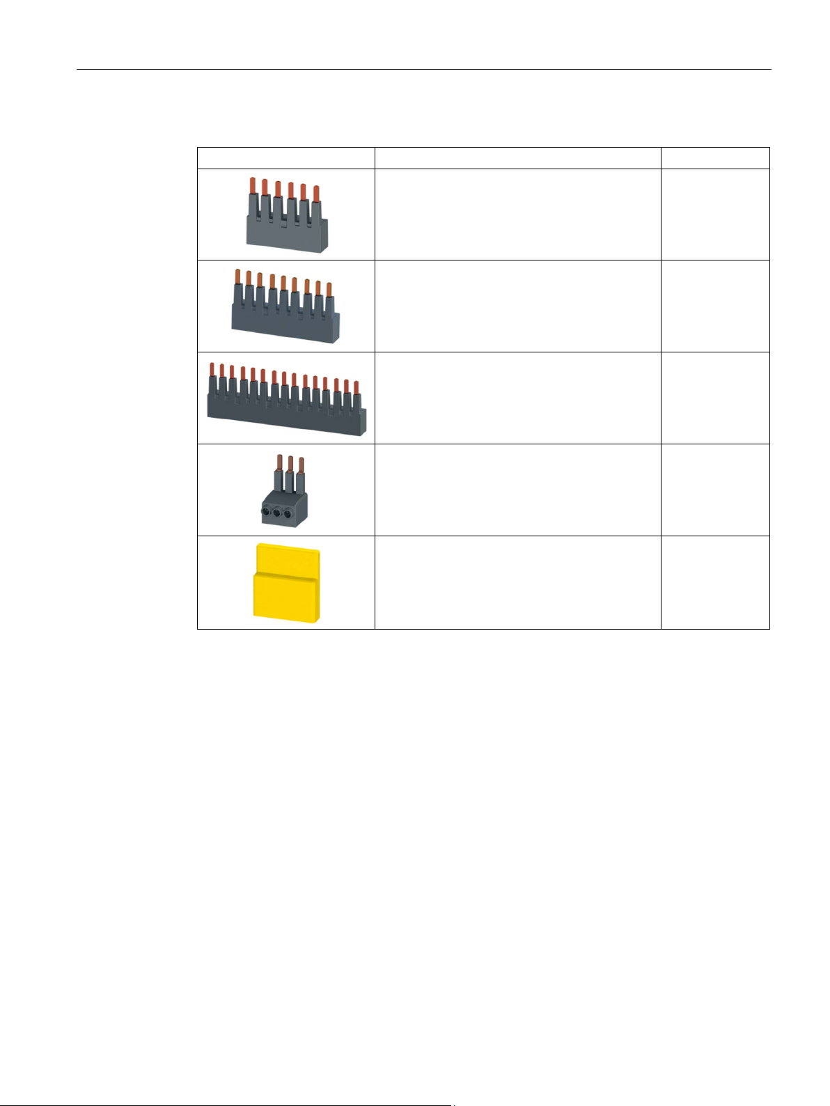
Description
Description
Article number
3.6.2.2
Fuse module
Function
3.6 Accessories and article number scheme
Table 3- 6 Infeed system article numbers
3-phase busbar for two 3RM1 motor starters 3RM1910-1AA
3-phase busbar for three 3RM1 motor starters 3RM1910-1BA
3-phase busbar for five 3RM1 motor starters 3RM1910-1DA
3-phase infeed terminal 3RM1920-1AA
Cover caps for terminal lugs of the 3-phase
busbars
3RM1910-6AA
A 3RM1 motor starter can be inserted in the fuse module. Various fuses can be fitted in the
fuse module to provide short-circuit protection. The fuse module can only be combined with
special 8US adapters. Power can be supplied from busbar systems when these adapters are
installed, or by conventional wiring when a special adapter is used.
SIRIUS 3RM1 motor starter
Manual, 06/2016, A5E0345285095020A/RS-AE/005
49
Page 50
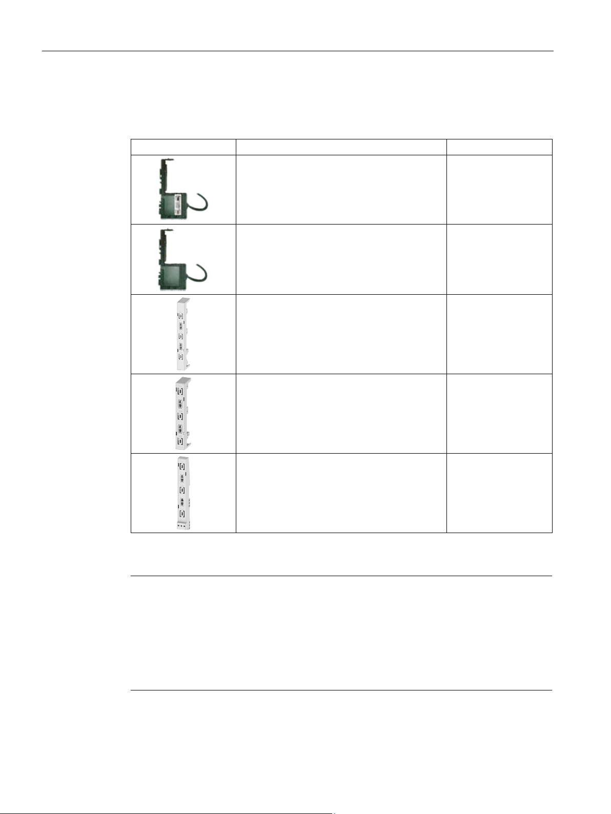
Description
Description
Article number
1) For use of alternative fuses
Note
•
•
•
3.6 Accessories and article number scheme
By using the fuse module, you can create an extremely compact load feeder.
Table 3- 7 Article numbers of the 3RM193 fuse module and the adapters
Fuse module with 20 A gG fuse 3NW6007-1
Fuse module without fuse1) 3RM1930-1AA
Busbar adapter for busbar system 8US1216-0AS00
Busbar adapter for compact busbar system 8US1616-0AK02
3RM1932-1AB
Adapter for standard mounting rails 8US1716-0RK00
You can use cylindrical 10 x 38 fuses, e.g. 3NW6… gG with maximum 25 A, or Class CC
with maximum 25 A.
The maximum load change stability is achieved with a fuse protection of 25 A. In this
2
case, a cable cross-section of 4 mm
is required for line protection.
You can only achieve equipment protection by installing fuse protection according to type
of coordination 2. Please refer to chapter "Load feeders - protection against short circuit
(Page 69)" for the relevant fuse specifications.
SIRIUS 3RM1 motor starter
50 Manual, 06/2016, A5E0345285095020A/RS-AE/005
Page 51
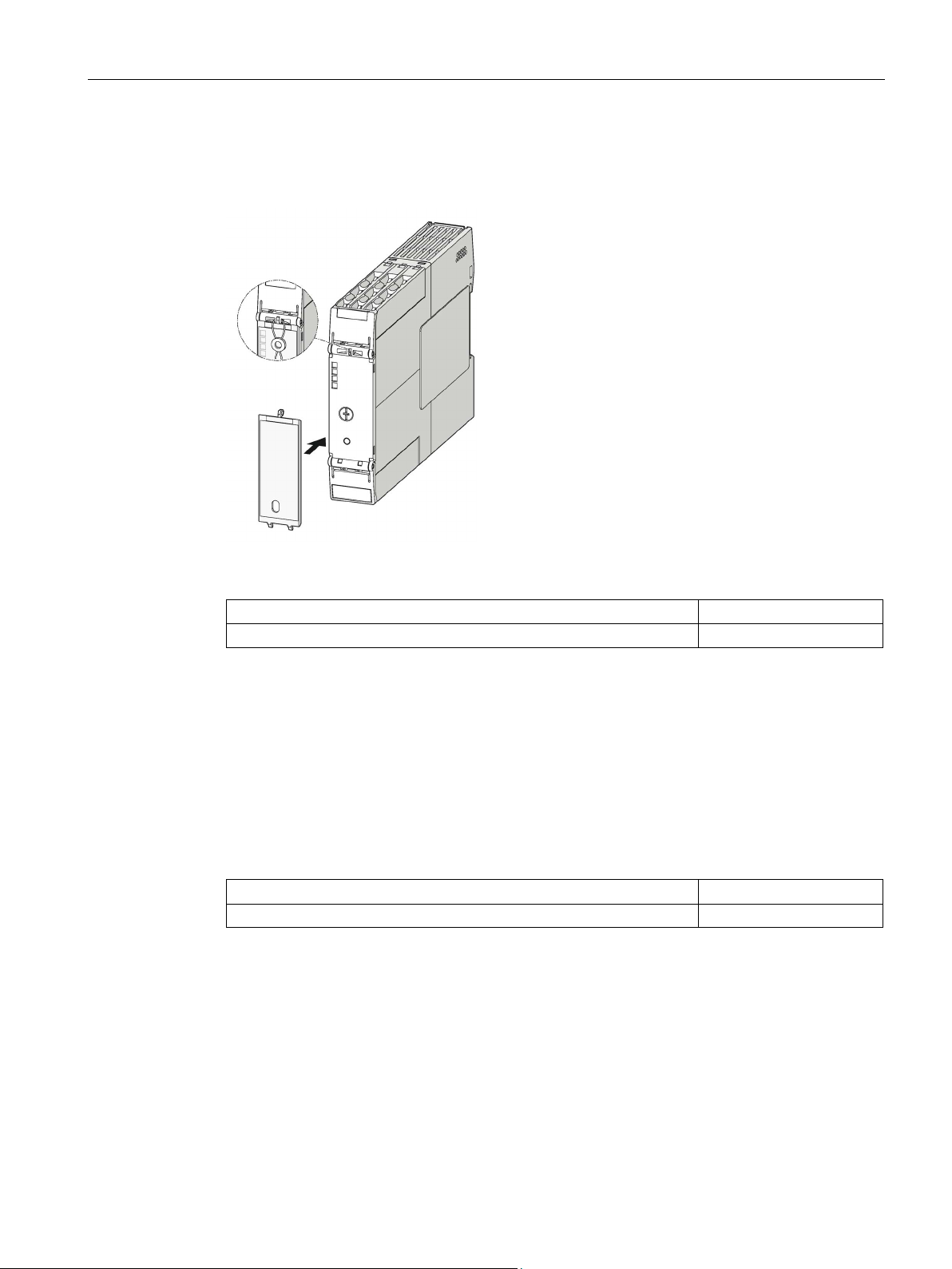
Description
3.6.2.3
Sealable cover
Description
Article number
3.6.2.4
Wall mounting
Description
Article number
SIRIUS push-in lugs for wall mounting
3ZY1311-0AA00
3.6 Accessories and article number scheme
The sealable cover prevents unauthorized access to the rotary coding switch.
Table 3- 8 Article number of the sealable cover
SIRIUS sealable cover 22.5 mm, cutout for pushbuttons at bottom 3ZY1321-2AA00
The push-in lugs for wall mounting of the 3RM1 motor starter are inserted at the top and
bottom of the motor starter enclosure. This method is used to screw the motor starter onto
level mounting surfaces.
The wall fixture is inserted into the enclosure at the top and bottom for screw-mounting the
3RM1 motor starter to level mounting surfaces.
Table 3- 9 Article numbers of the push-in lugs for wall mounting
SIRIUS 3RM1 motor starter
Manual, 06/2016, A5E0345285095020A/RS-AE/005
51
Page 52
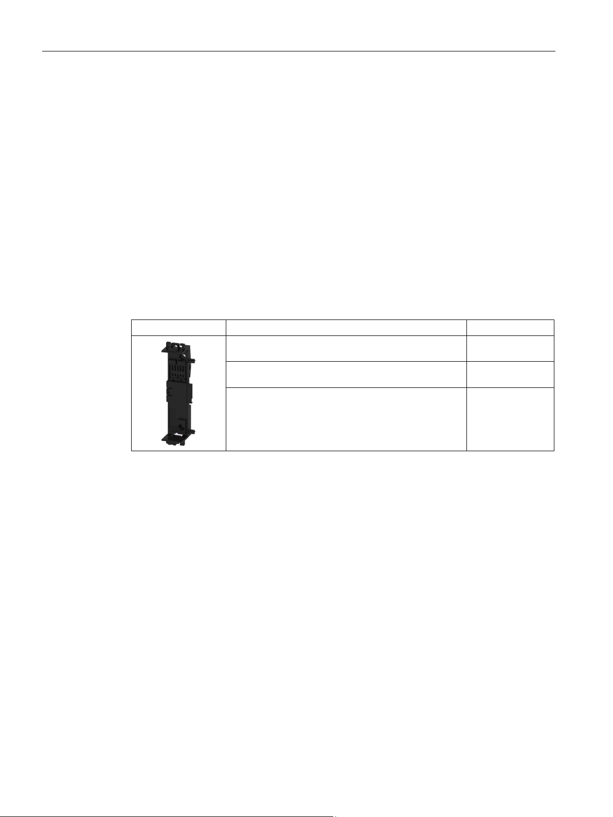
Description
3.6.2.5
Device connectors
Function
Description
Article number
22.5 mm wide
Use of device connectors exclusively for the 24 V DC control supply voltage
3.6 Accessories and article number scheme
The device connectors can be used to loop through a common control supply voltage of 24 V
DC to reduce wiring complexity between the individual motor starters (3RM1...-.AA04).
Moreover, Failsafe motor starters with a 24 V DC control supply voltage (3RM11...-.AA04 /
3RM13...-.AA04) can be interfaced to one 3SK safety relay as a group via device
connectors. The control signals are connected via the device terminals on the motor starter.
The device connectors can either be snapped onto a standard mounting rail or can be
screwed onto a flat mounting wall.
If the motor starters are not to be interconnected side by side, device connectors for looping
through signals must be used for the gaps, e.g. for thermal reasons (see "Derating
(Page 57)").
Table 3- 10 Article numbers for device connectors for 3RM1 motor starters
Device connector for 3RM1 motor starters,
Device connector for looping through signals,
22.5 mm wide
Device termination connector for 3RM1 motor starters,
22.5 mm wide
including left cover for the first device connector in the
system configuration
3ZY1212-2EA00
3ZY1212-2AB00
3ZY1212-2FA00
By using device connectors, several 3RM1...-.AA04 motor starters can be jointly supplied
with a control supply voltage of 24 V DC. This requires the control supply voltage to be
applied to the A1 and A2 terminals of only one motor starter.
Up to ten motor starters can be connected to one 24 V DC control supply voltage with device
connectors. The 24 V DC control supply voltage must be within the operating range of 0.9 to
1.1 for this purpose. If the full operating range of 0.8 to 1.25 is to be used, no more than five
3RM1...-.AA04 motor starters can be used. Otherwise, the infeed must be repeated for every
5th 3RM1 motor starter.
The last motor starter in a row can be placed on a device termination connector.
SIRIUS 3RM1 motor starter
52 Manual, 06/2016, A5E0345285095020A/RS-AE/005
Page 53
Description
Using device connectors with 3SK safety relays
WARNING
Loss of the safety function during hybrid operation of Failsafe and Standard motor starters.
Can cause death or serious injury.
WARNING
Loss of the safety function when using device connectors.
Can cause death or serious injury.
3.6 Accessories and article number scheme
Multiple 3RM11/3RM13 Failsafe motor starters can be connected in a group for joint safetyrelated shutdown by a 3SK safety relay. Safety-related applications up to SILCL 3 to EN
62061, PL e/Cat. 4 to EN ISO 13849-1 can be realized.
Hybrid operation of 3RM10/3RM12 Standard motor starters with 3RM11/3RM13 Failsafe
motor starters in safety-related applications is not admissible.
Only ever use safety-related motor starters (3RM11 Failsafe and 3RM13 Failsafe) in safetyrelated applications.
3RM1 motor starters are shut down by interrupting the control supply voltage by means of
the 3SK safety relay. For this reason, the control supply voltage must not also be applied to
the 3RM1 motor starters.
When the product is operated with a 3SK safety relay and a device connector, the supply
voltage for 3RM1 motor starters is fed in via the device connectors.
In this case, do not connect anything to terminals A1 and A2 of the 3RM1 motor starters, in
order to prevent bypassing of the safety function.
With device connectors, up to five Failsafe motor starters can be operated on one 3SK
safety relay. For configuration using 3SK safety relays, also follow the configuration rules in
the manuals for the "3SK Safety Relays"; see Chapter "Further documentation (Page 13)."
The last motor starter in a row must be placed on a device termination connector. This
closes the circuits that were built up with the connectors.
SIRIUS 3RM1 motor starter
Manual, 06/2016, A5E0345285095020A/RS-AE/005
53
Page 54

Description
Overview of all device connectors for 3RM1 motor starters and 3SK safety relays
Article number
Type of device connector
Units
wide
width 22.5 cm
Reference
3.6 Accessories and article number scheme
3ZY1212-2EA00 Device connector for 3RM1 motor starters, 22.5 mm wide
3ZY1212-2FA00 Device termination connector for 3RM1 motor starters, 22.5 mm wide
3ZY1212-2AB00 Device connector for looping through signals, 22.5 mm wide
3ZY1212-1BA00 Device connector for 3SK1 safety relay, 17.5 mm wide
3ZY1212-2BA00 Device connector for 3SK1 safety relay, 22.5 mm wide
3ZY1212-2DA00 Device termination connector for 3SK1 safety relay, 22.5 mm wide
3ZY1212-0FA01 Device termination connector set for 3SK1 safety relay, > 45 mm
3ZY1212-2GA00 Device connectors for 3SK2 safety relay, width 22.5 cm
3ZY1212-2AB00 Device connectors for 3SK2 safety relay for looping through signals,
3ZY1212-4GA01 Device connector set for 3SK2 safety relay, width 45 cm
• 3RM1 motor starter
• 3RM1 motor starter
• 3RM1 motor starter
• 3SK1120 safety relay
• 3SK1220 input expansion
• 3SK1121 safety relay
• 3SK1122 safety relay
• 3SK1211 output expansion
• 3SK1230 power supply
• 3SK1121 safety relay
• 3SK1122 safety relay
• 3SK1211 output expansion
• 3SK1213 output expansion
• 3SK2112 safety relay
• 3SK21 safety relay
• 3SK2122 safety relay
You will find further information on using device connectors in:
● "FAQs on the 3RM1 motor starter
(https://support.industry.siemens.com/cs/ww/en/view/81525494)"
● Manual "SIRIUS 3SK1 safety relays
(https://support.industry.siemens.com/cs/ww/de/view/67585885)"
● Manual "SIRIUS 3SK2 Safety Relays
(https://support.industry.siemens.com/cs/ww/de/view/109444336)"
SIRIUS 3RM1 motor starter
54 Manual, 06/2016, A5E0345285095020A/RS-AE/005
Page 55
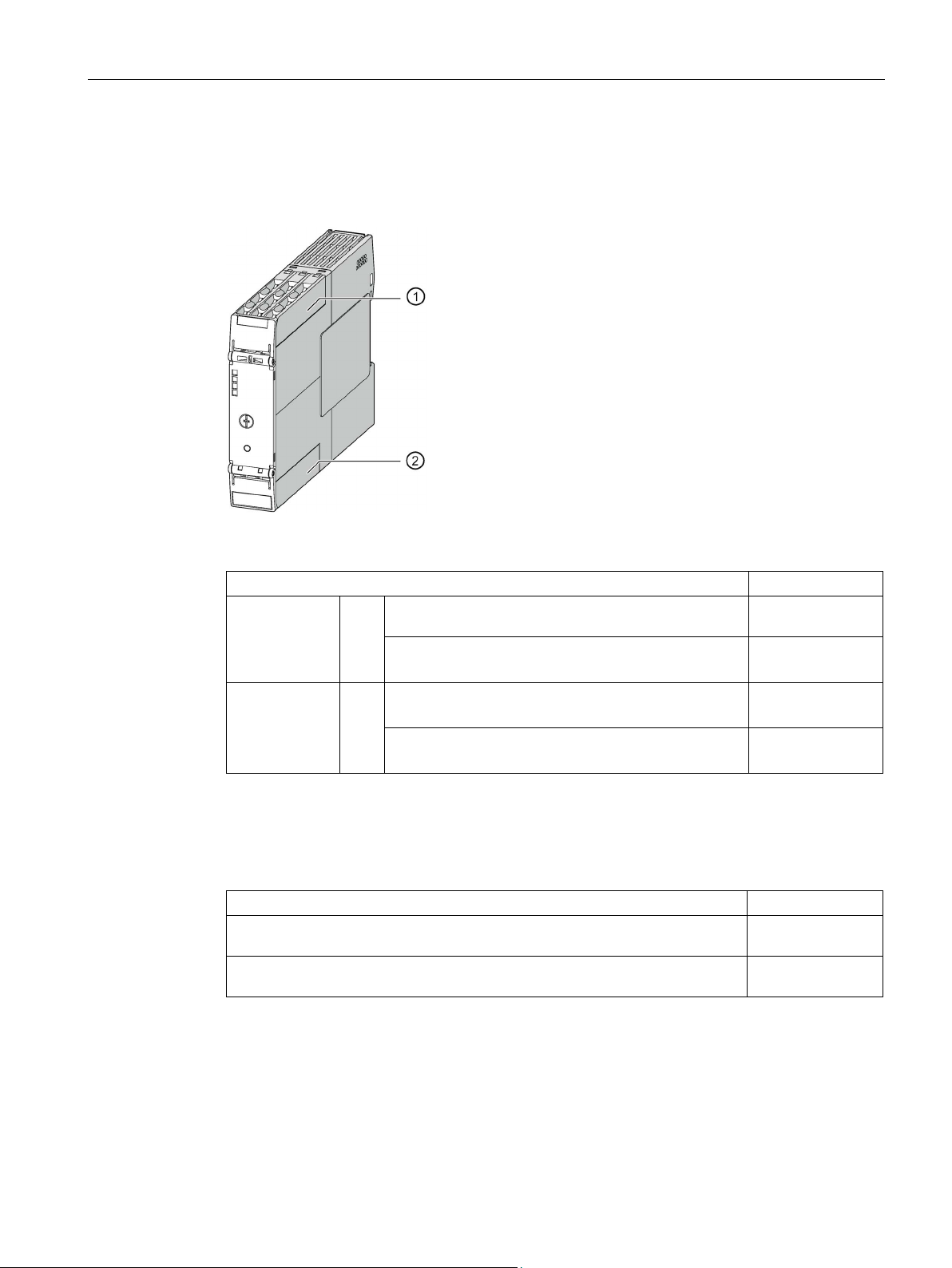
Description
3.6.2.6
Terminals
Description
Article number
1x2.5 mm²
push-in terminals up to 2x1.5 mm²
screw terminals up to 1x4 mm²
push-in terminals up to 1x4 mm² or 2x1.5 mm²
3.6.2.7
Device identification label
Description
Article number
snapping into place, size 20 x 7 mm, in box
3.6 Accessories and article number scheme
Each 3RM1 motor starter has three main current terminals and three control current
terminals. The terminals can be replaced with ease.
Table 3- 11 Article numbers for the terminals
Control current
terminals
Detachable terminal, 3-pole, screw terminals up to
①
Detachable 3-pole terminal,
3ZY1131-1BA00
3ZY1131-2BA00
Main current
terminals
Table 3- 12 Article numbers for the device identification labels
SIRIUS device identification label, titanium gray, 17 mats each with 20 labels for
SIRIUS device identification label, titanium gray, 10 sheets each with 306
adhesive labels, size 19 x 6 mm, in transparent bag
Detachable 2-pole terminal,
②
Detachable 2-pole terminal,
3ZY1122-1BA00
3ZY1122-2BA00
3RT2900-1SB20
3RT2900-1SB60
SIRIUS 3RM1 motor starter
Manual, 06/2016, A5E0345285095020A/RS-AE/005
55
Page 56
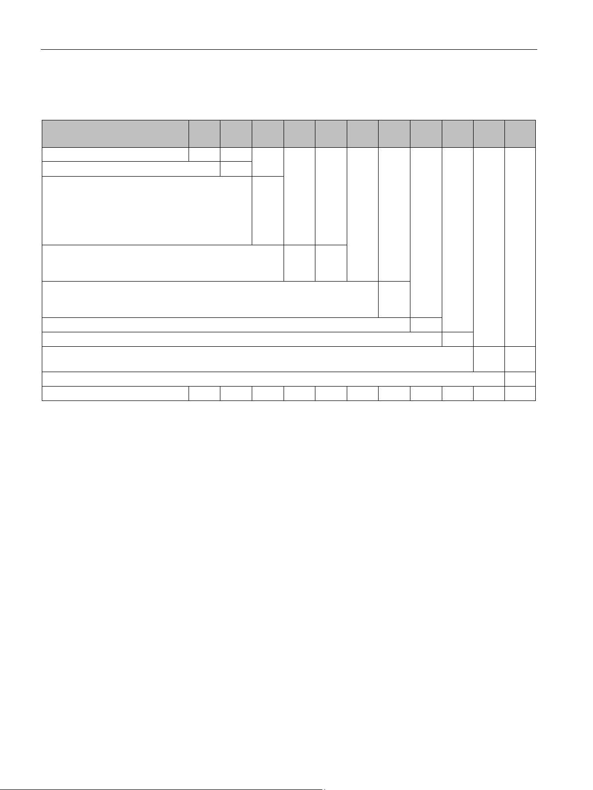
Description
3.6.3
Article number scheme for SIRIUS 3RM1 motor starter
Digit of the Article No.
1. - 3.
❒❒❒
4. ❒ 5. ❒ 6. ❒ 7. ❒ - 8. ❒ 9. ❒ 10. ❒ 11. ❒ 12.
❒
SIRIUS 3RM1 motor starter
3RM
Generation
Function
accessories = 9)
Setting range rated motor current
1.6 ... 7.0 A = 07)
Connection type
hybrid connection method*) = 3)
Reserved (A)
❒
Width (22.5 mm = A)
❒
Rated control supply voltage
110 ... 230 V AC /110 V DC = 1)
Rated operating voltage (48 ... 500 V = 4)
❒
Example
3RM
1 0 0 1 - 1 A A 0
4
*) Hybrid connection method: control circuit realized as push-in spring-loaded terminal and main circuit as screw terminal
3.6 Accessories and article number scheme
direct-on-line starter Failsafe & ATEX
certification = 1;
reversing starter = 2;
reversing starter Failsafe & ATEX certification = 3;
(1) ❒
(Direct-on-line starter = 0,
❒
0.4 ... 2.0 A = 02;
(screw terminal = 1,
push-in spring-loaded terminal = 2,
(24 V DC = 0;
(0.1 ... 0.5 A = 01;
❒ ❒
❒
❒
SIRIUS 3RM1 motor starter
56 Manual, 06/2016, A5E0345285095020A/RS-AE/005
Page 57

4
4.1
Rated operational current
Values for rated operational current Ie
Motor starter version
3RM1.01-.....
3RM1.02-.....
3RM1.07-.....
Setting range for Ie [A]
0.1 ... 0.5
0.4 ... 2
1.6 ... 7 (10)
Minimum current per phase of the motorized load [A]
0.05
0.14
0.6
Note
The devices with I
10
suitable for operating motors. With this setting, there is no overload trip in accordance with
Class
"
Derating factors
Depending on the current setting range, the following rated operational currents apply for the
3RM1 motor starters:
Rated operational current I
As soon as the minimum current limit is violated, fault detection (phase failure) picks up.
eAC53a
A in the highest setting level. This setting is intended for resistive loads to 10 A and is not
10A. Instead, this takes place in accordance with the description in the chapter
Overload protection/device protection characteristic (Page 145)".
The maximum settable rated operational current decreases depending on the following
factors:
● Installation altitude
● High motor starting current (> 8x starting current)
● Ambient temperature
[A] 0.5 2 7
eAC53a
= 7 A have in addition to this setting value an I
setting value for
eAC51
SIRIUS 3RM1 motor starter
Manual, 06/2016, A5E0345285095020A/RS-AE/005
57
Page 58
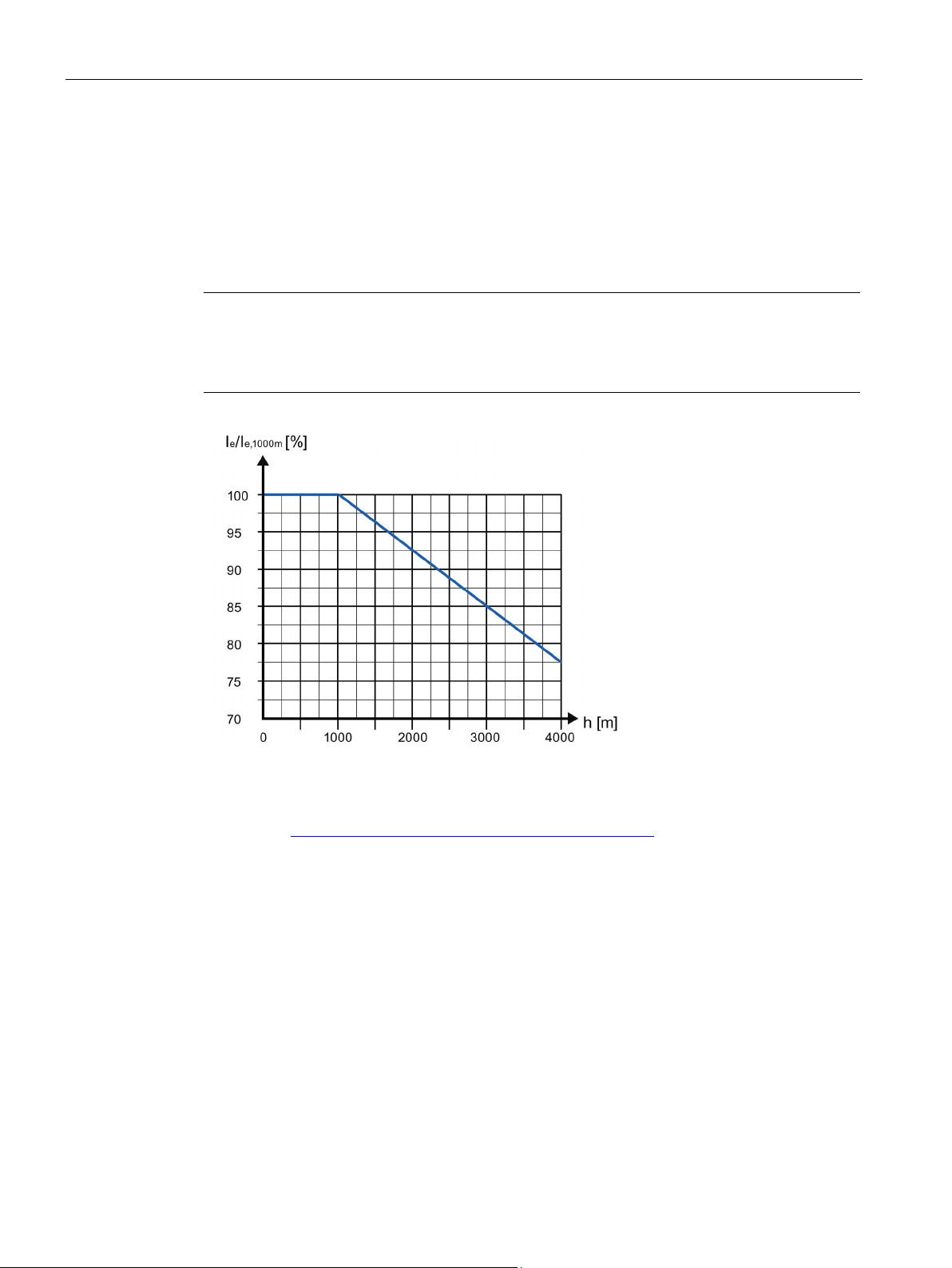
Configuration
4.2
Derating at high installation altitudes (> 2 000 m)
Dependence of the rated operational current on the installation altitude
Note
Maximum installation altitude of 3RM11 / 3RM13 Failsafe motor starters: 2000 m
Installation altitudes of more than 2000 m are not permissible for 3RM11/3RM13 Failsafe
motor starters.
4.2 Derating at high installation altitudes (> 2 000 m)
The permissible rated operational current of the 3RM1 motor starter is reduced as shown in
the diagram depending on the installation altitude.
From an installation altitude in excess of 2000 m, in the case of Standard 3RM10/3RM12
motor starters the maximum permissible operational voltage must be reduced due to the
limited insulation strength. You can obtain details on request from SIEMENS Technical
Assistance (http://www.siemens.com/sirius/technical-assistance).
SIRIUS 3RM1 motor starter
58 Manual, 06/2016, A5E0345285095020A/RS-AE/005
Page 59
Configuration
4.3
Derating with high motor starting current
Motors with a high efficiency and high motor starting currents
Motor starter version
I
eAC53a
[A] at 40 °C max. motor
starting current
3RM1.01-.....
3RM1.02-.....
3RM1.07-.....
<= 8-fold Ie
0.5 2 7
9-fold Ie
0.45
1.8
6.2
9.5-fold Ie
0.42
1.7
5.9
10-fold Ie
0.4
1.6
5.6
4.3 Derating with high motor starting current
High starting currents may have to be taken into consideration when using 3RM1 motor
starters on motors with a high efficiency (IE3 or IE4). According to the product standard
IEC 60947-4-2, the 3RM1 motor starters are designed for motors with a maximum 8-fold
starting current.
If motors are operated that have a higher starting current, refer to the following table for the
maximum adjustable motor current:
Table 4- 1 Maximum settable motor current
8.5-fold Ie 0.47 1.9 6.6
The device protection may respond sooner in the case of motors with a higher starting
current. You will find details in "Overload protection/device protection characteristic
(Page 145)".
SIRIUS 3RM1 motor starter
Manual, 06/2016, A5E0345285095020A/RS-AE/005
59
Page 60
Configuration
4.4
Derating with high ambient temperature
4.4.1
Maximum ambient temperature for 3RM1.01 (0.5 A) and 3RM1.02 (2 A)
Mounting position
Max. ambient temperature for 0.5 A and 2 A device for AC 53 a
Side-by-side
Individually/with 22.5 mm clearance
Vertically on horizontal rail
50 °C
60 °C
Horizontally on vertical rail
45 °C
60 °C
rail/mounting surface
4.4.2
Derating for 7 A devices
4.4 Derating with high ambient temperature
For the versions 0.5 A and 2 A, the following ambient temperature limits apply depending on
the mounting position:
Upright on horizontal
The maximum settable rated operational current for 3RM1.07 motor starters depends on the
following factors:
● The utilization category: AC 53a / AC 51
● The mounting position: Vertical / horizontal / upright
● The design version: Individually / Alternately / Side-by-side
● Accessories: Device connector / Fuse module
45 °C 60 °C
SIRIUS 3RM1 motor starter
60 Manual, 06/2016, A5E0345285095020A/RS-AE/005
Page 61
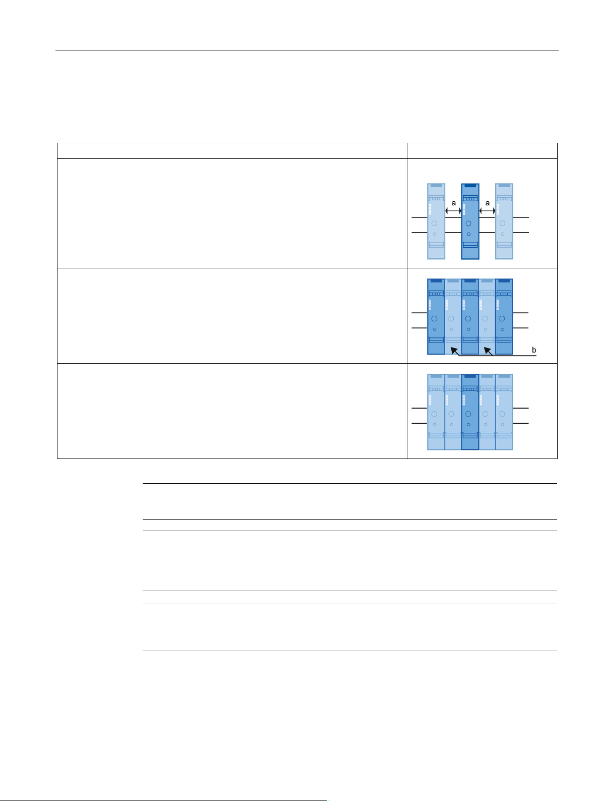
Configuration
Design versions for 7 A devices:
Design version
Note
Please note the assembly
Note
When using the 3
leaving the connections free. Cover the free connections with cover caps (accessories). This
will protect the free terminal lugs against touch.
Note
If you are using fuse modules on 8US…
earances
by installing cover profiles for
4.4 Derating with high ambient temperature
For the 7 A device without clearance, a distinction is made between the following design
versions:
Individually with clearance a = 22.5 mm
Can be implemented with signal loop-through connectors when using device
connectors.
Note:
When using the 3-phase busbar systems, the necessary clearances can also be
implemented by leaving the connections free. Cover the free connections with cover
caps (accessories) to protect the free terminal lugs against touch.
7 A device alternately with 2 A device or 0.5 A device (b) without clearance
Devices with the same rated operational current without clearance: Side-by-side
examples in Chapter "Typical circuits (Page 167)".
-phase busbar system, you can achieve the necessary clearances by
busbars, you can achieve the necessary cl
8US1922… busbars.
SIRIUS 3RM1 motor starter
Manual, 06/2016, A5E0345285095020A/RS-AE/005
61
Page 62

Configuration
Maximum ambient temperature for 3RM1.07 (7 A)
Utilization category AC 53 a:
Mounting position
Ambient
temperature
in °C
Max. setting values for 7 A device in A for AC 53 a with
design version
Individually/with
22.5 mm clearance
Alternately with
2 A device
Side-by-side
40
7 / 6.52)
4.6 4 45
6.1 4 3.6
55
5.2 0 0
40
5.2 4 3.2
45
4.6 2 2
50 4 0 0 55
3.2 0 0
60
2.0 0 0
40
6.1 4 3.6
45
5.2
3.6
3.2
50
5.2 0 0
55 4 0
0
60
3.6 0 0
1)
2)
With fuse module
Utilization category AC 51 (resistive loads):
Ambient temperature
in °C
Max. setting values for 7 A device in A for AC 51
Individually/with
22.5 mm clearance
Alternately with 2 A
device
Side-by-side
40
10 / 8.51)
4.6
4.6
45 7 3.2
3.2
50 7 3.2
3.2
55
5.2 0 0
60
5.2 0 0
1)
With fuse module
4.4 Derating with high ambient temperature
The permissible rated operational current of the 3RM1.07 motor starter decreases
depending on the mounting position, the design version and the ambient temperature T
For the 7 A version, the following derating values apply depending on the mounting position
and the installation version:
Vertically on horizontal rail
50 6.1 3.2 / 2.81) 3.2 / 2.41)
60 4.6 0 0
Horizontally on vertical rail
U.
Upright on horizontal
rail/mounting surface
When using device connectors
The permissible rated operational current of the 3RM1.07 motor starter decreases for
utilization category AC 51 depending on the design version and the ambient temperature T
as follows:
U
SIRIUS 3RM1 motor starter
62 Manual, 06/2016, A5E0345285095020A/RS-AE/005
Page 63

Configuration
4.5
Ambient conditions
4.5.1
Application environment
Note
If you operate
adequately ventilated.
4.5.2
Ambient temperature
4.5.3
Mounting position
4.5 Ambient conditions
The 3RM1 motor starters are designed for use in enclosed spaces in which no severe
operating conditions prevail (e.g. dust, caustic vapors, hazardous gases).
If they are to be installed in dusty or damp rooms, suitable control cabinets must be
provided.
the 3RM1 motor starter in a control cabinet, ensure that the cabinet is
The 3RM1 motor starter has been designed for use under ambient temperatures ranging
from -25 °C to +40 °C, singly in a vertical mounting position, and without a reduction in the
permissible rated operational current. With the deratings given in the section "Rated
operational current (Page 57)", you can operate the 3RM1 motor starters at ambient
temperatures of up to 60 °C.
Installation on a vertical mounting surface is recommended for the 3RM1 motor starter.
Please observe the power reduction levels/deratings for other mounting positions given in
the section "Rated operational current (Page 57)".
SIRIUS 3RM1 motor starter
Manual, 06/2016, A5E0345285095020A/RS-AE/005
63
Page 64
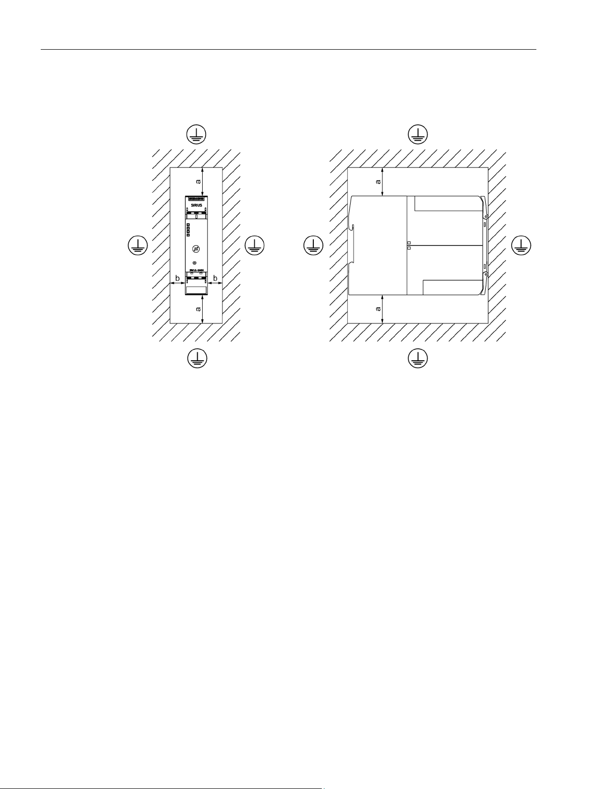
Configuration
Dimension drawing showing clearance to be maintained from grounded parts for the RM1 motor
starter
a =
50 mm
b =
3.5 mm
4.5 Ambient conditions
Figure 4-1 Dimension drawing 3RM1 with grounding clearances, side and front
SIRIUS 3RM1 motor starter
64 Manual, 06/2016, A5E0345285095020A/RS-AE/005
Page 65
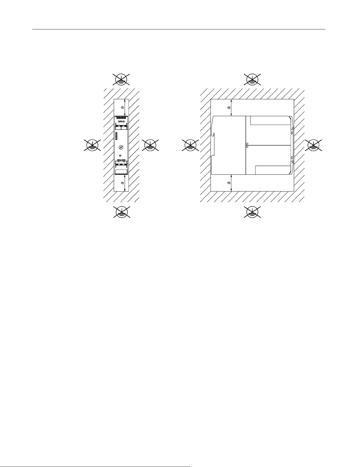
Configuration
Dimension drawing showing clearances to be maintained with side-by-side mounting of 3RM1 motor
starters
a =
50 mm
4.5 Ambient conditions
Figure 4-2 Dimension drawing 3RM1 with clearances for side-by-side mounting, side and front, not
grounded
SIRIUS 3RM1 motor starter
Manual, 06/2016, A5E0345285095020A/RS-AE/005
65
Page 66
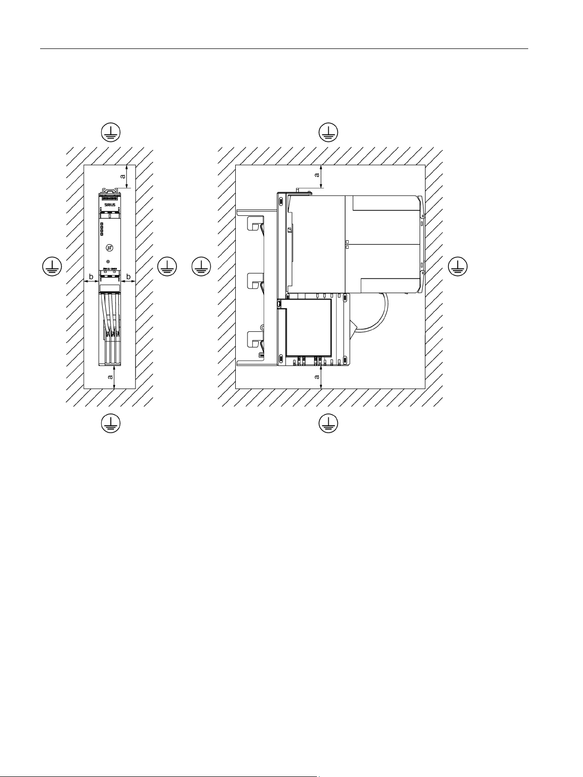
Configuration
Dimension drawing showing clearance to be maintained from grounded parts for the 3RM19 fuse
module with 3RM1 motor starter
a
= 50 mm
b
= 3.5 mm
4.5 Ambient conditions
Figure 4-3 Front view and side view
SIRIUS 3RM1 motor starter
66 Manual, 06/2016, A5E0345285095020A/RS-AE/005
Page 67
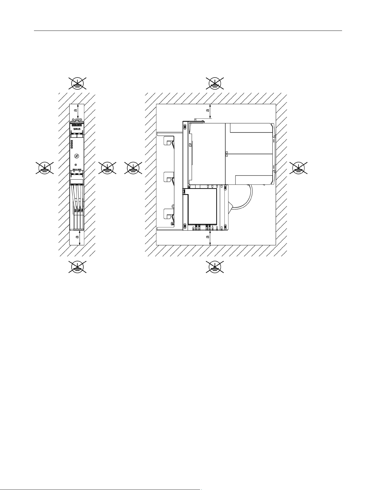
Configuration
Dimension drawing showing clearance to be maintained with side-by-side mounting of 3RM19 fuse
module with 3RM1 motor starter
a
= 50 mm
4.5 Ambient conditions
Figure 4-4 Front view and side view
SIRIUS 3RM1 motor starter
Manual, 06/2016, A5E0345285095020A/RS-AE/005
67
Page 68

Configuration
4.5.4
Grounding measures
4.5.5
Permissible operating voltage
Control circuit
(A1/A2, OUT, IN1-3,
M1/M2)
Signaling contacts
(98/95/96)
Main circuit
(1L1/3L2/5L3
2T1/4T2/6T3)
Control circuit
(A1/A2, OUT, IN1-3,
M1/M2)
Signaling contacts
(98/95/96)
Main circuit
(1L1/3L2/5L3
2T1/4T2/6T3)
4.5.6
Minimum load current
Motor current
0.5 A
2 A
7 A
Motorized load
0.05 A
0.14 A
0.6 A
Resistive load
0.05 A
0.14 A
0.6 A
Motor current
0.5 A
2 A
7 A
Motorized load
0.05 A
0.14 A
0.6 A
Resistive load
0.25 A
1 A
3.5 A
4.5 Ambient conditions
No grounding measures are required for the 3RM1 motor starter.
To be able to ensure safe isolation of the circuits from each other in accordance with IEC
60947-1, the following operating voltages are permissible:
Table 4- 2 Safe isolation of the 3RM1 motor starters
... to ...
- 250 V 500 V
250 V - 500 V
500 V 500 V -
The minimum load current is 20% of the set motor current, but at least the absolute minimum
current specified in the tables below.
The minimum load current differs in the case of Standard 3RM10/3RM12 and Failsafe
3RM11/3RM13 motor starters:
Table 4- 3 Minimum load current in the case of Standard 3RM10/3RM12 motor starters
Table 4- 4 Minimum load current in the case of Failsafe 3RM11/3RM13 motor starters
SIRIUS 3RM1 motor starter
68 Manual, 06/2016, A5E0345285095020A/RS-AE/005
As soon as the minimum current limit is violated, fault detection (phase failure) picks up.
Page 69
Configuration
4.6
Load feeders - protection against short circuit
4.6.1
Protection against short circuit
DANGER
Hazardous voltage at the motor
Will cause death, serious injury, or damage to property.
Health hazard from automatic hot restart.
type of
coordination 1
type of coordination 2
4.6.2
Configuration of load feeders
4.6.3
Configuration of a load feeder with 3RM1 motor starter in compliance with IEC
4.6 Load feeders - protection against short circuit
The short-circuit strength in combination with fuses is up to 100 kA at 400 V and with SIRIUS
3RV2 motor starter protectors up to 55 kA at 400 V. Type of coordination 1 is maintained
here.
The safety function must be checked after every tripping of the motor starter protector (also
in the case of overload).
After every short circuit in the case of short-circuit protection according to
, a 3RM1 motor starter is defective.
Replace a 3RM1 motor starter including the terminals after a short circuit in the case of
short-circuit protection according to type of coordination 1.
With 3RM11 / 3RM13 Failsafe motor starters, you must check the safety functions in
addition to replacing the unit.
With 3RM11 / 3RM13 Failsafe motor starters, also check the safety functions after a short
circuit in the case of short-circuit protection according to
The 3RM1 motor starters can be combined with any short-circuit protection devices. Using
SIRIUS 3RV20 motor starter protectors offers a convenient solution for the configuration of
fuseless load feeders. However, combinations with fuses are also possible, mastering
particularly high short-circuit currents. Type of coordination 2 (see Glossary (Page 189)) can
also be achieved. To achieve a particularly compact design, 3RM193 fuse modules can be
installed as well.
Short-circuit protection for load feeders in compliance with IEC can also be realized by motor
starter protectors or fuses. Depending on the design of the protection device, the two types
of coordination 1 or 2 can be achieved. The protection devices listed are the maximum
permissible versions and, as an alternative, protection devices of the same type with a lower
rated current can be used.
.
SIRIUS 3RM1 motor starter
Manual, 06/2016, A5E0345285095020A/RS-AE/005
69
Page 70
Configuration
4.6.3.1
Fuseless design
Combining 3RM1 motor starters with motor starter protectors
DANGER
Hazardous voltage at the motor
Will cause death, serious injury, or damage to property.
Health hazard from automatic hot restart.
type of
coordination 1
type of coordination 2
Motor starter TA = 40 °C
Short-circuit
current
Maximum permitted motor starter
protectors
for 400 V + 10%
Article number
Rated current [A]
Current [kA]
Article number
Rated current [A]
3RM1...
0.5 / 2.0 / 7.0
55
3RV2011-1HA..
8
3RM1...
0.5 / 2.0 / 7.0
12.5
3RV2011-1KA..
12.5
3RM1...
0.5 / 2.0 / 7.0
10
3RV2021-4AA..
16
3RM1...
0.5 / 2.0 / 7.0
7.5
3RV2021-4BA..
20
3RM1...
0.5 / 2.0 / 7.0
5
3RV2021-4DA..
25
Motor starter TA = 40 °C
Short-circuit
current
Maximum permitted motor starter
protectors
for 500 V + 10%
Article number
Rated current [A]
Current [kA]
Article number
Rated current [A]
3RM1.01…
0.5
10
3RV2011-1HA..
8
3RM1.02…
2.0
10
3RV2011-1HA..
8
3RM1.07…
7.0
10
3RV2011-1HA..
8
4.6 Load feeders - protection against short circuit
The safety function must be checked after every tripping of the motor starter protector (also
in the case of overload).
After every short circuit in the case of short-circuit protection according to
, a 3RM1 motor starter is defective.
Replace a 3RM1 motor starter including the terminals after a short circuit in the case of
short-circuit protection according to type of coordination 1.
With 3RM11 / 3RM13 Failsafe motor starters, you must check the safety functions in
addition to replacing the unit.
With 3RM11 / 3RM13 Failsafe motor starters, check the safety functions after a short circuit
in the case of short-circuit protection according to
The 3RM1 motor starters can be combined with the following motor starter protectors for
short circuits according to type of coordination 1:
.
Table 4- 5 Motor starter protectors according to type of coordination 1 for 3RM1 motor starters with
400 V
Table 4- 6 Motor starter protectors according to type of coordination 1 for 3RM1 motor starters with
500 V
SIRIUS 3RM1 motor starter
70 Manual, 06/2016, A5E0345285095020A/RS-AE/005
Page 71
Configuration
Combining 3RM1 motor starters with miniature circuit breakers
DANGER
Hazardous voltage at the motor
Will cause death, serious injury, or damage to property.
Health hazard from automatic hot restart.
type of
coordination 1
type of coordination 2
Motor starter TA = 40 °C
Short-circuit
current
Maximum permitted miniature circuit
breakers
with 400 V + 10%
Article number
Rated current [A]
Current [kA]
Article number
Rated current [A]
3RM1.01…
0.5 6 5SY4325-6
25
3RM1.07…
7.0 6 5SY4325-6
25
4.6.3.2
Fused design
4.6 Load feeders - protection against short circuit
The safety function must be checked after every tripping of the motor starter protector (also
in the case of overload).
After every short circuit in the case of short-circuit protection according to
, a 3RM1 motor starter is defective.
Replace a 3RM1 motor starter including the terminals after a short circuit in the case of
short-circuit protection according to type of coordination 1.
With 3RM11 / 3RM13 Failsafe motor starters, you must check the safety functions in
addition to replacing the unit.
With 3RM11 / 3RM13 Failsafe motor starters, check the safety functions after a short circuit
in the case of short-circuit protection according to
.
The 3RM1 motor starters can be combined with the following miniature circuit breakers for
short circuits according to type of coordination 1:
Table 4- 7 Miniature circuit breakers according to type of coordination 1 for 3RM1 motor starters
with 400 V
3RM1.02… 2.0 6 5SY4325-6 25
On tested assemblies, the type of coordination defines the permissible condition of devices
following a short-circuit.
Type of coordination 1 means that the load feeder may be non-operational after a short
circuit has been cleared.
Type of coordination 2 means that the 3RM1 motor starter is still operational following a
short-circuit.
With the 3RM1 motor starter, short-circuit protection is only provided by fuses up to 400 V
(+10%) for type of coordination 2.
SIRIUS 3RM1 motor starter
Manual, 06/2016, A5E0345285095020A/RS-AE/005
71
Page 72
Configuration
Combining 3RM1 motor starters with fuses for type of coordination 1
DANGER
Hazardous voltage at the motor
Will cause death, serious injury, or damage to property.
type of
coordination 1
Motor starter TA = 40 °C
Maximum permitted fuse links
for 500 V + 10 %
DIAZED operating class gG
Rated current [A]
Article number
Rated current [A]
3RM1.01…
0.5
5SB281 / 3NW6010-1
25
3RM1.07…
7.0
5SB281 / 3NW6010-1
25
Combining 3RM1 motor starters with fuses for type of coordination 2
DANGER
Hazardous voltage at the motor
Will cause death, serious injury, or damage to property.
Health hazard from automatic hot restart.
type of coordination 2
4.6 Load feeders - protection against short circuit
The safety function must be checked after every tripping of the motor starter protector (also
in the case of overload).
After every short circuit in the case of short-circuit protection according to
, a 3RM1 motor starter is defective.
Replace a 3RM1 motor starter including the terminals after a short circuit in the case of
short-circuit protection according to type of coordination 1.
With 3RM11/3RM13 Failsafe motor starters, you must check the safety function in addition
to replacing the unit.
The 3RM1 motor starters can be combined with the following fuses for short circuits of 55 kA
according to type of coordination 1:
Table 4- 8 Fuses according to type of coordination 1 for 3RM1 motor starters
3RM1.02… 2.0 5SB281 / 3NW6010-1 25
The safety function must be checked after every tripping of the motor starter protector (also
in the case of overload).
With 3RM11/3RM13 Failsafe motor starters, check the safety function after a short circuit in
the case of short-circuit protection according to
.
SIRIUS 3RM1 motor starter
72 Manual, 06/2016, A5E0345285095020A/RS-AE/005
Page 73

Configuration
Motor starter TA = 40 °C
Short-circuit current
Maximum permissible fuse links at 400 V + 10%
operational class gG
Article number
Rated current [A]
Current [kA]
Article number
Rated current [A]
3RM1.01...
0.5 2 FR10GR69V20 (make: Mersen)
20
3RM1.02...
2.0 2 FR10GR69V20 (make: Mersen)
20
4.6.4
Configuration of a load feeder with 3RM1 motor starter in compliance with UL
4.6.4.1
Function according to UL 508
4.6.4.2
Configuration of individual load feeders
SCCR short circuit current ratings
4.6 Load feeders - protection against short circuit
The 3RM1 motor starters can be combined with the following fuses for short-circuits
according to type of coordination 2: In a fused configuration with 3RM1 motor starters,
please observe the dimensioning information of the fuse manufacturer.
Table 4- 9 Fuses according to type of coordination 2 for 3RM1 motor starters at 400 V
3RM1.07... 7.0 2 FR10GR69V20 (make: Mersen) 20
The 3RM1 motor starters can be combined individually with a circuit breaker (motor starter
protector) or fuses. A group installation is also possible according to UL.
A circuit breaker or appropriate fuses is/are assigned to each motor starter.
The SCCR (short circuit current rating) indicates the maximum permissible short-circuit
current for a switching device. A higher value can only be achieved in combination with
protection devices such as fuses or circuit breakers.
This rating is required for mounting accessories in control cabinets (control panels)
conforming to UL 508a. The switching device or switchgear assembly with the lowest value
specifies the value for the entire control panel.
A low value makes engineering the supply voltage for the control panel difficult.
According to UL 508a, the 3RM1 motor starters have a standard short circuit current rating of
1 kA for the versions up to 2 A rated current and 5 kA for the version with 7 A.
Tests were also carried out with a short circuit rating of 100 kA (high capacity short circuit
current ratings). The UL reports
(https://support.industry.siemens.com/cs/ww/en/view/66427510) include details of possible
combinations with Class J fuses, as well as with a number of circuit breakers.
SIRIUS 3RM1 motor starter
Manual, 06/2016, A5E0345285095020A/RS-AE/005
73
Page 74
Configuration
Circuit breakers for protecting against short-circuit currents
DANGER
Hazardous voltage at the motor
Will cause death, serious injury, or damage to property.
Standard short circuit according to UL 508 for 460 V + 5 %
Motor starter TA = 50 °C
Short-circuit current
Circuit breaker
Article number
Rated current [A]
[kA]
Type
Max. size [A]
3RM1.01...
0.5 1 3RV2711
6.3
3RM1.07...
6.1 5 3RV2711 / 2721
22
High SCCR according to UL 508 for 460 V + 5 %
Motor starter TA = 50 °C
Short-circuit current
Circuit breaker
Article number
Rated current [A]
[kA]
Type
Max. size [A]
3RM1.01…
0.5
65
3RV2711
2.5
3RM1.02…
2.0
65
3RV2711
2.5
3RM1.07…
6.1
18
3RV2711
10
4.6 Load feeders - protection against short circuit
Health hazard from automatic hot restart.
The 3RM1 motor starter and the safety function must be checked after every tripping of the
motor starter protector (also in the case of overload).
Replace a defective 3RM1 motor starter including the terminals after a short circuit. With
3RM11 / 3RM13 Failsafe motor starters, you must check the safety functions in addition to
replacing the unit.
Table 4- 10 Circuit breakers for protecting against short-circuit currents
3RM1.02... 2.0 1 3RV2711 6.3
Table 4- 11 Circuit breakers for protecting against high short-circuit currents
SIRIUS 3RM1 motor starter
74 Manual, 06/2016, A5E0345285095020A/RS-AE/005
Page 75
Configuration
Fuses for protection from short-circuit currents
DANGER
Hazardous voltage at the motor
Will cause death, serious injury, or damage to property.
Standard short circuit according to UL 508 for 460 V + 5 %
Motor starter TA = 50 ℃
Short-circuit current
Fuse
Article number
Rated current [A]
[kA]
Type
Max. size [A]
3RM1.01…
0.5 5 RK 5
8
3RM1.07…
6.1 5 RK 5
30
High SCCR according to UL 508 for 460 V + 5 %
Motor starter TA = 50 ℃
Short-circuit current
Fuse
Article number
Rated current [A]
[kA]
Type
Max. size [A]
3RM1.01…
0.5
100
CLASS J
35
3RM1.02…
2.0
100
CLASS J
35
3RM1.07…
6.1
100
CLASS J
35
4.6 Load feeders - protection against short circuit
Health hazard from automatic hot restart.
The 3RM1 motor starter and the safety function must be checked after every tripping of the
motor starter protector (also in the case of overload).
Replace a defective 3RM1 motor starter including the terminals after a short circuit. With
3RM11 / 3RM13 Failsafe motor starters, you must check the safety functions in addition to
replacing the unit.
Table 4- 12 Fuses for protecting against short-circuit currents
3RM1.02… 2.0 5 RK 5 8
Table 4- 13 Fuses for protecting against high short-circuit currents
SIRIUS 3RM1 motor starter
Manual, 06/2016, A5E0345285095020A/RS-AE/005
75
Page 76
Configuration
4.6.4.3
Configuring a group of load feeders (group installation)
SCCR short-circuit current rating
Circuit breakers for protecting against short-circuit currents
DANGER
Hazardous voltage at the motor
Will cause death, serious injury, or damage to property.
Standard short circuit according to UL 508 for 460 V + 5 %
Motor starter TA = 50 °C
Short-circuit current
Circuit breaker
Article number
Rated current [A]
[kA]
Type
Max. size [A]
3RM1.01...
0.5 5 3RV2711 / 2721
22
3RM1.02...
2.0 5 3RV2711 / 2721
22
3RM1.07...
6.1 5 3RV2711 / 2721
22
4.6 Load feeders - protection against short circuit
A "group installation" is a combination of several 3RM1 motor starters with one common
short-circuit protection device (branch circuit protection device). This common branch circuit
protection device can be a circuit breaker according to UL489, e.g. a 3RV27 or fuses
according to UL248.
The 3RM19 infeed system is suitable for a group installation according to UL because it can
be loaded up to a total current of 16 A. As an alternative, distribution of the main circuit can
be realized with individual cables that have an AWG 12 cross-section or with infeed system
16 A, with a different distribution, for example, "Power Distribution blocks" 5ST2-5
distribution blocks. Whether loading with a total current of >16 A is possible depends on the
tested assembly.
For further information, see Certificate of Compliance CoC
(https://support.industry.siemens.com/cs/ww/en/view/66427510).
The SCCR (short circuit current rating) indicates the maximum permissible short-circuit
current for a switching device. A higher value can only be achieved in conjunction with
protection devices such as fuses or circuit breakers.
This rating is required for mounting accessories in control cabinets (control panels)
conforming to UL 508a. The switchgear assembly with the lowest value specifies the value
for the entire control panel.
Health hazard from automatic hot restart.
The 3RM1 motor starter and the safety function must be checked after every tripping of the
motor starter protector (also in the case of overload).
Replace a defective 3RM1 motor starter including the terminals after a short circuit. With
3RM11 / 3RM13 Failsafe motor starters, you must check the safety functions in addition to
replacing the unit.
Table 4- 14 Circuit breakers for protecting against short-circuit currents
SIRIUS 3RM1 motor starter
76 Manual, 06/2016, A5E0345285095020A/RS-AE/005
Page 77
Configuration
High SCCR according to UL 508 for 460 V + 5 %
Motor starter TA = 50 ℃
Short-circuit current
Circuit breaker
Article number
Rated current [A]
[kA]
Type
Max. size [A]
3RM1.01…
0.5
10
3RV2711
12.5
3RM1.02…
2.0
10
3RV2711
12.5
Fuses for protection from short-circuit currents
DANGER
Hazardous voltage at the motor
Will cause death, serious injury, or damage to property.
Standard short circuit according to UL 508 for 460 V + 5 %
Motor starter TA = 50 ℃
Short-circuit current
Fuse
Article number
Rated current [A]
[kA]
Type
Max. size [A]
3RM1.01…
0.5 5 RK 5
30
3RM1.02…
2.0 5 RK 5
30
3RM1.07…
6.1 5 RK 5
30
4.6 Load feeders - protection against short circuit
Table 4- 15 Circuit breakers for protecting against high short-circuit currents
3RM1.07… 6.1 10 3RV2711 12.5
Health hazard from automatic hot restart.
The 3RM1 motor starter and the safety function must be checked after every tripping of the
motor starter protector (also in the case of overload).
Replace a defective 3RM1 motor starter including the terminals after a short circuit. With
3RM11 / 3RM13 Failsafe motor starters, you must check the safety functions in addition to
replacing the unit.
Table 4- 16 Fuses for protecting against short-circuit currents
SIRIUS 3RM1 motor starter
Manual, 06/2016, A5E0345285095020A/RS-AE/005
77
Page 78

Configuration
High SCCR according to UL 508 for 460 V + 5 %
Motor starter TA = 50 ℃
Short-circuit current
Fuse
Article number
Rated current [A]
[kA]
Type
Max. size [A]
3RM1.01…
0.5
100
CLASS J
35
3RM1.02…
2.0
100
CLASS J
35
Motor starter TA = 50 ℃
Fuse
Article number
Rated current [A]
Short circuit
current [kA]
Type
Max. size [A]
3RM1...
0.5 / 2.0 / 6.1
50
CLASS CC
20
Motor starter TA = 50 ℃
Fuse
Connecting cable
Article number
Rated current [A]
Short circuit
current [kA]
Type
Max. size
[A]
5.5 lb-in
4.6 Load feeders - protection against short circuit
Table 4- 17 Fuses for protecting against high short-circuit currents
3RM1.07… 6.1 100 CLASS J 35
Table 4- 18 Fuses to provide protection against high short-circuit currents for use with the
3RM193 fuse module on 8US1216-0AS00 and 8US1616-0AK02 busbar adapters
3RM1... 0.5 / 2.0 / 6.1 100 3NW3250-0HG 25
Table 4- 19 Fuses to provide protection against high short-circuit currents for use with the
3RM193 fuse module on the 8US1716-0RK00 standard mounting rail adapter
3RM1... 0.5 / 2.0 / 6.1 50 CLASS CC 20 AWG 24-10
SIRIUS 3RM1 motor starter
78 Manual, 06/2016, A5E0345285095020A/RS-AE/005
Page 79

Configuration
4.7
Infeed for the main circuit
4.7.1
Infeed options
4.7.2
3RM19 3-phase infeed system
Note
Use of several busbars
More than five devices can be
rotated by 180°.
A motor starter must be plugged into the connection points of the busbars. Observe this in
the case of gaps stipulated for derating purposes, and select appr
4.7 Infeed for the main circuit
You have the following options for implementing the infeed for the main circuit of the 3RM1
motor starter:
● Infeed via parallel wiring of individual 3RM1 motor starters
● Infeed via the 3RM19 infeed system (for 3RM1...-1AA.4 motor starters with screw
connections and 3RM1...-3AA.4 motor starters with hybrid connections)
● Infeed via the 3RM193 fuse module (for all 3RM1 motor starters)
The 3RM19 3-phase infeed system is designed for 3RM1...-1AA.4 motor starters with screw
connections and 3RM1...-3AA.4 motor starters with hybrid connections. Push-in terminals
can therefore not be connected with this infeed system.
connected by clamping the terminal lugs of a second busbar
opriate busbars.
The special 3-phase busbar enables fault-free and fast main circuit wiring when using
several 3RM1 motor starters arranged side-by-side. The energy is routed from an upstream
short-circuit protection device to the system via an infeed terminal. The 3-phase busbar is
designed in such a way that the maximum number of 3RM1 motor starters is only limited by
the rated operational current of the infeed system.
SIRIUS 3RM1 motor starter
Manual, 06/2016, A5E0345285095020A/RS-AE/005
79
Page 80
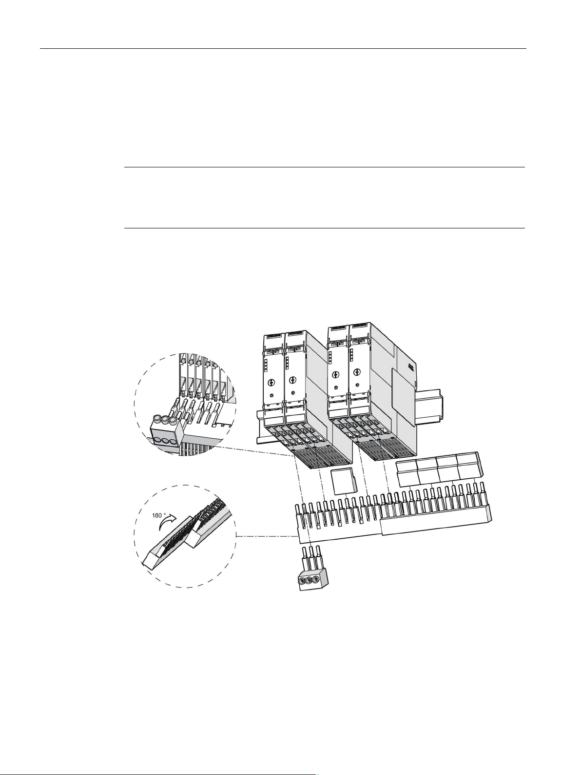
Configuration
Rated operational current
Note
Multiple infeed
If you plan multiple infeed in the case of a respective requirement of more than 25
must observe a potential current asymmetry in the infeeds.
Mounting
4.7 Infeed for the main circuit
For the components of the 3RM19 infeed system, the maximum permissible rated
operational current is 25 A (UL: 16 A).
If you use several 3RM1 motor starters that together require more than 25 A, form groups
that each have a maximum requirement of 25 A (UL: 16 A).
A, you
Attach the busbar from below to the rear terminals L1, L2 and L3 of the 3RM1 motor starter.
The outgoing feeders to the motors thus remain accessible.
Figure 4-5 Attaching the 3RM19 infeed system to the 3RM1 motor starters
SIRIUS 3RM1 motor starter
80 Manual, 06/2016, A5E0345285095020A/RS-AE/005
Page 81
Configuration
DANGER
Hazardous voltage.
Will cause death or serious injury.
4.7.3
3RM193 fuse module
Rated operational current
Assembly
4.7 Infeed for the main circuit
If free and uncovered terminal lugs are touched when the load voltage is switched on,
death or serious physical injury will result.
For this reason, always cover the free terminal lugs (= free slots that are unassigned for
thermal reasons, for example) with a cover cap. The cover caps are available as
accessories.
Energy is supplied via the infeed terminal 3RM1920-1AA. This means you can connect
conductors with a cross-section of 1.5 mm² to 4 mm².
A fuse module can be used to create a very compact design of load feeder. The 3RM1 motor
starter in combination with the integrated fuses for short-circuit protection can be used on
8US busbar systems or on standard mounting rails.
The fuse module can be installed using a variety of different 8US adapters:
● In all 60 mm busbar systems
● In compact busbar systems
● On standard mounting rails
The interface to the adapter permits simple and safe replacement of the load feeder.
The fuse module can be combined with all 3RM1 motor starters. The easily replaceable
fuses protect the motor starter, the connected motor and the cables.
The maximum permissible rated operational current for the 3RM193 fuse module is 25 A.
1. Connect the motor starter to terminals L1, L2 and L3.
2. Connect up the motor feeder cables.
3. Mount the assembled load feeder on an adapter.
SIRIUS 3RM1 motor starter
Manual, 06/2016, A5E0345285095020A/RS-AE/005
81
Page 82
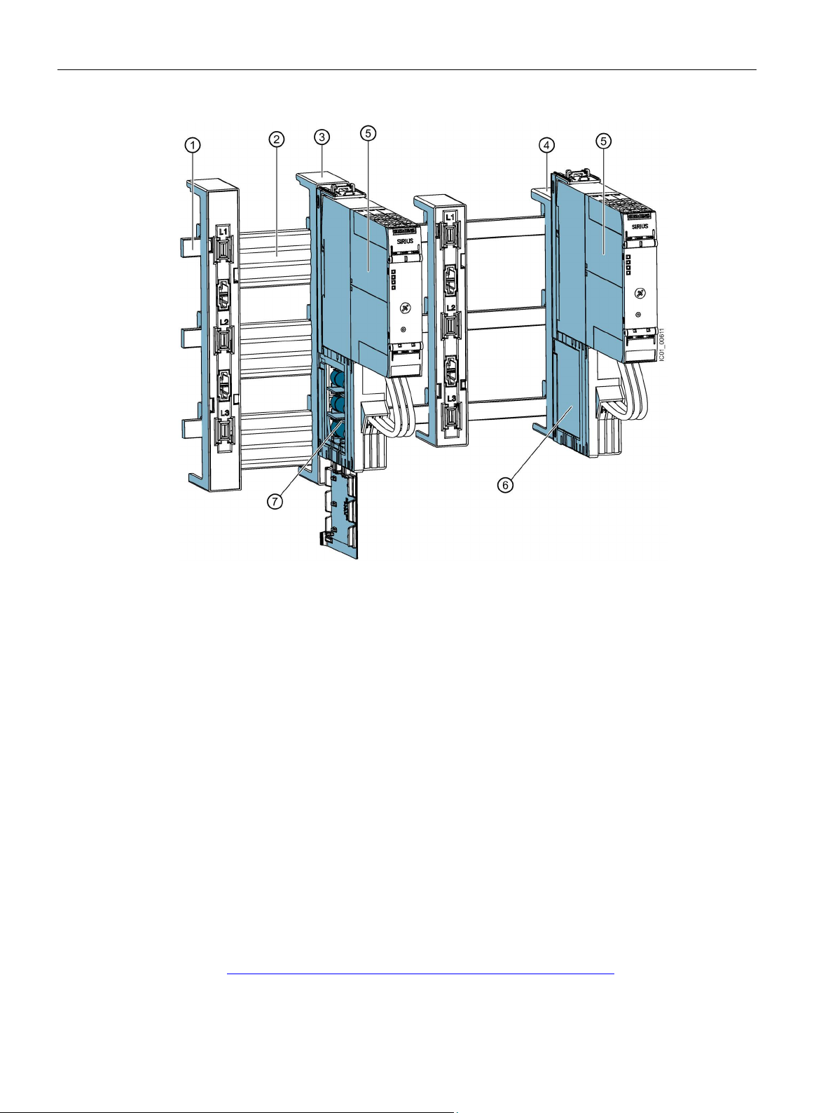
Configuration
①
Busbar system
②
Cover profiles for busbars
③
Busbar adapter
④
Compact busbar adapter
⑤
3RM1 motor starter
⑥
3RM19 fuse module
⑦
removed to change the fuses.
4.8
Configuration with device connectors
4.8 Configuration with device connectors
3RM19 fuse module with open flap
The flap cannot be opened when the fuse module is inserted. The fuse module must be
Figure 4-6 An assembled busbar system with fuse modules
The device connector may be used only with the 24 V DC version of the motor starter. There
must be no mixing of the Standard and Failsafe variants of the 3RM1 motor starter via the
device connector. If both variants are used, these must be fitted on separate device
connector systems. This has no influence on the infeed system for the 3RM19 main circuit,
which can still be used without restriction for a combination of the variants.
For additional information on using device connectors, refer to "FAQs on the 3RM1 motor
starter (https://support.industry.siemens.com/cs/ww/en/view/81525494)".
SIRIUS 3RM1 motor starter
82 Manual, 06/2016, A5E0345285095020A/RS-AE/005
Page 83
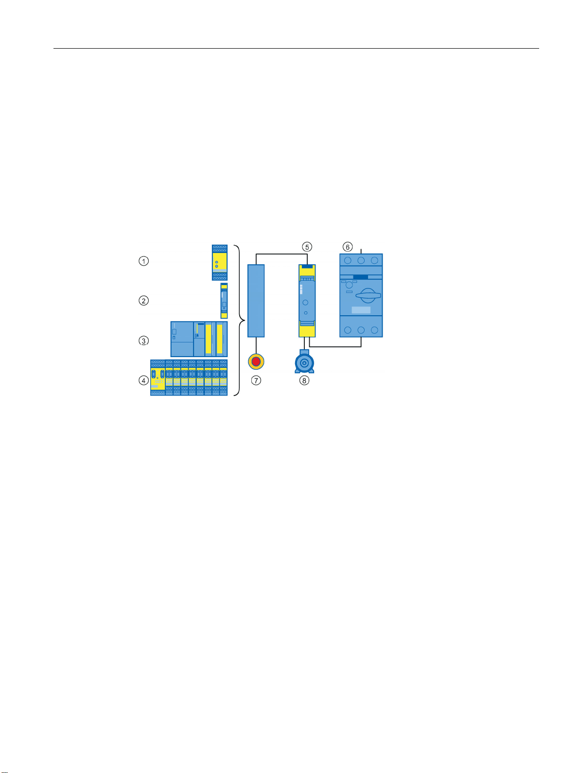
Configuration
4.9 Examples/applications
4.9 Examples/applications
4.9.1 Operation with the EMERGENCY-STOP function
The 3RM11 Failsafe and 3RM13 Failsafe safety-related motor starters can be used with any
safety relays and safety-related controllers in safety-related applications up to SILCL 3 in
accordance with IEC 62061, PL e/Cat. 4 in accordance with EN ISO 13849-1.
Basic configuration
① ... ④ Instead of the black box, one of the modules ① ... ④ can be used
① SIRIUS 3TK28 safety relay
② SIRIUS 3SK safety relay
③ SIMATIC S7 fail-safe modules
④ SIRIUS 3RK3 modular safety system
⑤ SIRIUS 3RM11 Failsafe or SIRIUS 3RM13 Failsafe safety-related motor starter
⑥ SIRIUS 3RV2 motor starter protector
⑦ EMERGENCY-STOP button
⑧ Motor
Figure 4-7 Basic configuration with safety relay or safety-related controller
SIRIUS 3RM1 motor starter
Manual, 06/2016, A5E0345285095020A/RS-AE/005
83
Page 84
Configuration
Configuration with 3SK safety relay and device connectors
WARNING
Loss of the safety function when using device connectors.
Can cause death or serious injury.
WARNING
Loss of the safety function during hybrid operation of Failsafe and Standard motor starters.
Can cause death or serious injury.
Note
Please observe the information about the control supply voltage and the control inputs in
Chapter "
(
4.9 Examples/applications
If you use safety-related motor starters (3RM11..-.AA04 / 3RM13..-.AA04) with a control
supply voltage of 24 V DC with the 3SK safety relay, you can establish safe connection of
the safety-related wiring using the device connectors. Use of device connectors avoids
errors when setting up the control circuit wiring and offers savings in cable laying. In addition,
the test overhead following completion of the control cabinets is reduced. The
3RM11/3RM13 safety-related motor starters can be used optimally as output expansions in
the 3SK system.
When the EMERGENCY-STOP is actuated, the motor starters' control supply voltage is shut
down and the motor is isolated from the power supply. Due to the internal self-monitoring of
the 3RM11/13 Failsafe motor starters in compliance with SILCL 3/PL e, there is no need for
a feedback signal to the 3SK safety relay.
When the product is operated with a 3SK safety relay and a device connector, the supply
voltage for 3RM11 / 3RM13 motor starters is fed in via the device connectors.
In this case, do not connect anything to terminals A1 and A2 of the 3RM11/3RM13 Failsafe
motor starters, in order to prevent bypassing of the safety function.
Hybrid operation of 3RM10/3RM12 Standard motor starters with 3RM11/3RM13 Failsafe
motor starters in safety-related applications is not admissible.
Only ever use safety-related motor starters (3RM11 Failsafe and 3RM13 Failsafe) in safetyrelated applications.
Device versions (Page 29)" and in the "Technical Data Sheet
https://support.industry.siemens.com/cs/ww/en/ps/16311/td)."
SIRIUS 3RM1 motor starter
84 Manual, 06/2016, A5E0345285095020A/RS-AE/005
Page 85
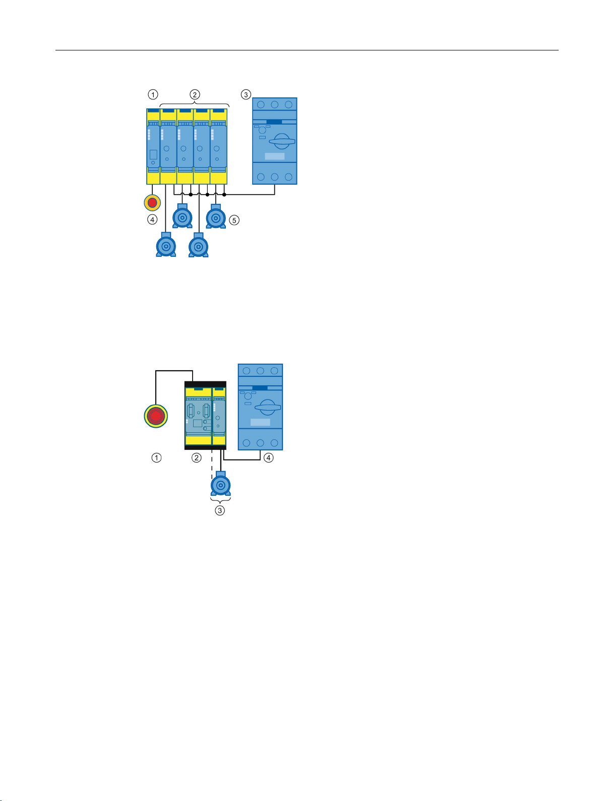
Configuration
①
SIRIUS 3SK1 Advanced basic unit
②
SIRIUS 3RM1 Failsafe (3RM11 Failsafe or 3RM13 Failsafe) safety-related motor starters
③
SIRIUS 3RV2 motor starter protector
④
SIRIUS 3SU1 EMERGENCY STOP
⑤
Motor
①
SIRIUS 3SU1 EMERGENCY STOP
②
3SK2 safety relay
③
3RM1 Failsafe motor starter and motor
④
SIRIUS RV2 motor starter protector
Reference
4.9 Examples/applications
Figure 4-8 Configuration with 3SK1 safety relay and device connectors
Figure 4-9 Configuration with 3SK2 safety relay and device connectors
You will find further information on operation in safety-related applications in the 3SK safety
relay manuals, see Chapter "Further documentation (Page 13)." Follow the safety
instructions and information contained there.
You will find more typical circuits in the Appendix "Typical circuits (Page 167)."
SIRIUS 3RM1 motor starter
Manual, 06/2016, A5E0345285095020A/RS-AE/005
85
Page 86

Configuration
4.9 Examples/applications
SIRIUS 3RM1 motor starter
86 Manual, 06/2016, A5E0345285095020A/RS-AE/005
Page 87
5
5.1
Warning notices
Warning notices before installation, wiring, and commissioning
DANGER
Hazardous voltage.
Will cause death or serious injury.
NOTICE
Damage caused by electrostatic charge
Turn off and lock out all power supplying this device before working on this device.
When handling and installing the 3RM1 motor starters, ensure that the components are
protected from electrostatic charge. Changes to the system configuration and wiring are
only permissible in the voltage-free state.
Connection of 3RM11 / 3RM13 Failsafe motor starters is only permissible when the power
supply units (PELV and SELV) are switched off.
SIRIUS 3RM1 motor starter
Manual, 06/2016, A5E0345285095020A/RS-AE/005
87
Page 88
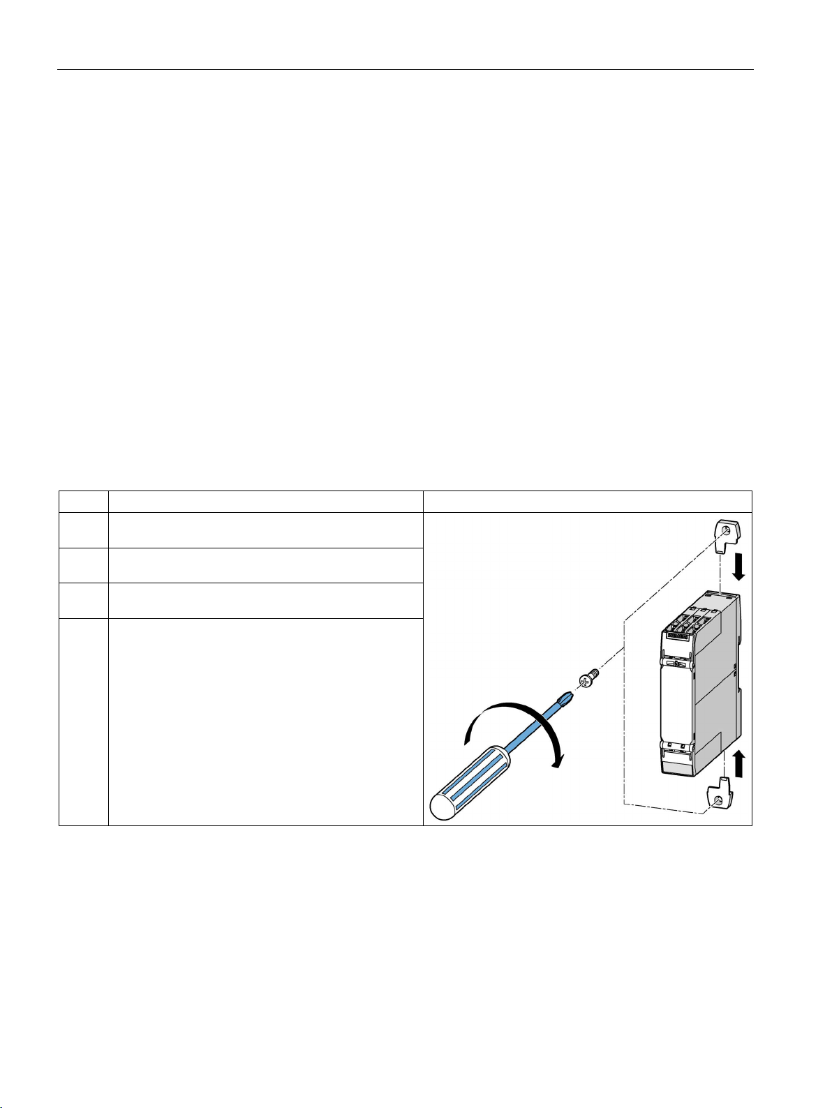
Mounting
5.2
Mounting the devices on a level surface
Requirements
Procedure
Step
Operating instruction
Figure
provided on the device until they engage.
securing brackets.
5.2 Mounting the devices on a level surface
Please note the following requirements for mounting on a level surface:
● Please observe the information about the mounting position in the chapter "Mounting
position (Page 63)".
● Two properly executed drill holes with thread or plug on the level surface
For details of the distances between the drilled holes, please refer to the relevant
dimension drawings in the chapter "Dimension drawings (Page 149)".
● Two screws to fit the holes M4 x 12 in accordance with DIN 784
● Two plastic securing brackets
Refer to the accessories list for the relevant article number in the chapter "Accessories
and article number scheme (Page 47)".
1 Insert the securing brackets into the openings
2 Hold the device up to the level surface prepared for
screw fastening.
3 Insert the screws through the oblong holes in the
4 Screw the device onto the level surface so that it is
secure.
Tightening torque: 1 Nm
SIRIUS 3RM1 motor starter
88 Manual, 06/2016, A5E0345285095020A/RS-AE/005
Page 89
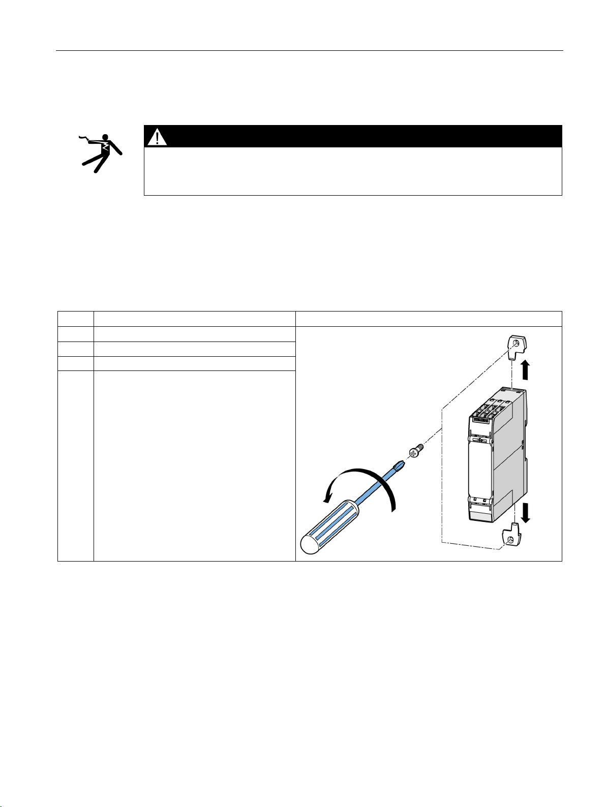
Mounting
5.3
Disassembling the devices from a level surface
DANGER
Hazardous voltage.
Will cause death or serious injury.
Requirements
Procedure
Step
Operating instruction
Figure
1
Hold the device firmly.
2
Unscrew the cap screws.
3
Lift the device from the level surface.
5.3 Disassembling the devices from a level surface
Turn off and lock out all power supplying this device before working on this device.
● The terminals have been removed or disconnected.
4 Remove the securing brackets from the device.
SIRIUS 3RM1 motor starter
Manual, 06/2016, A5E0345285095020A/RS-AE/005
89
Page 90
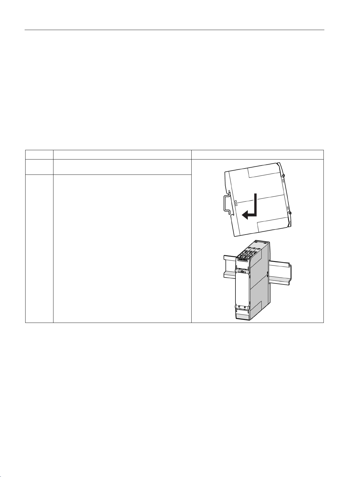
Mounting
5.4
Mounting the devices on a standard mounting rail
Requirements
Procedure
Step
Operating instruction
Figure
standard mounting rail
5.4 Mounting the devices on a standard mounting rail
● At the installation location, a horizontal 35 mm mounting rail in accordance with
DIN EN 60715 is properly secured
● Please observe the information about the mounting position in chapter "Mounting position
(Page 63)"
1 Hang the back of the device onto the upper edge of the
2 Press the lower half of the device against the rail until
the device engages
SIRIUS 3RM1 motor starter
90 Manual, 06/2016, A5E0345285095020A/RS-AE/005
Page 91
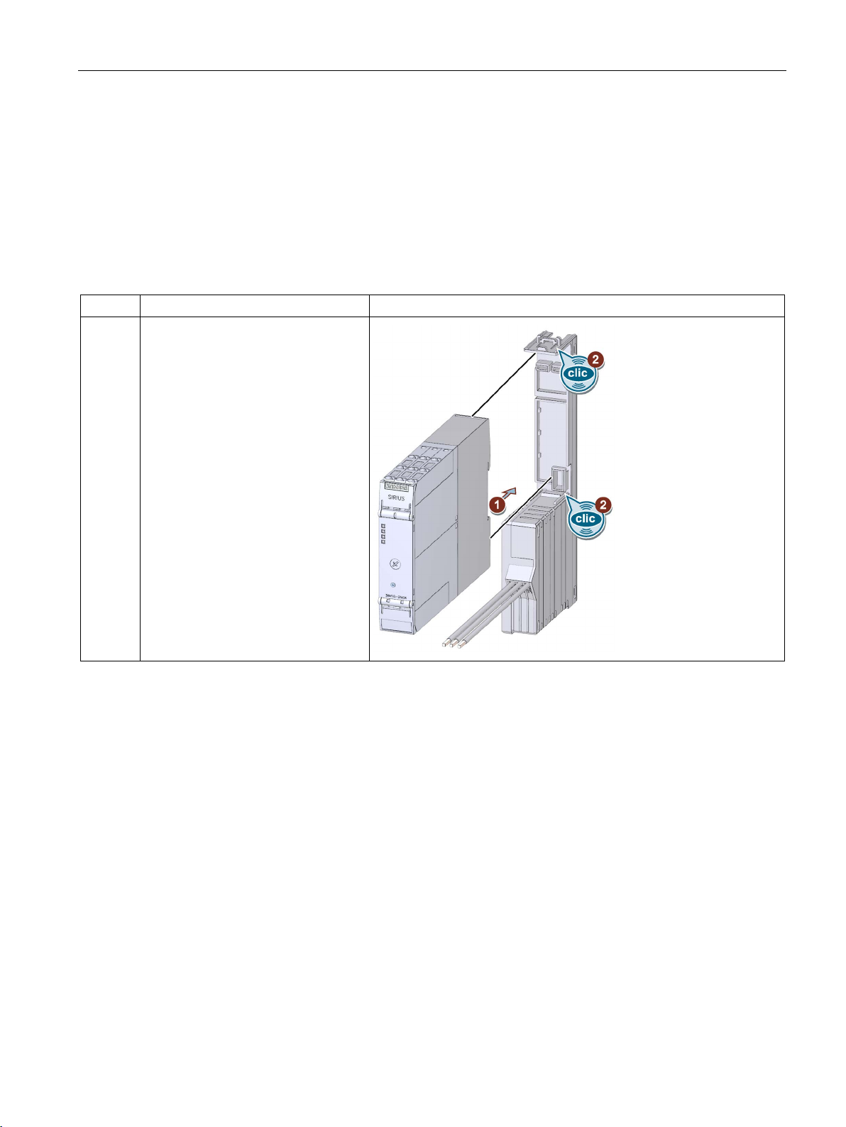
Mounting
5.5
Mounting the devices on a fuse module
Requirements
Procedure
Step
Description
Figure
See also
5.5 Mounting the devices on a fuse module
Make sure the rated operational current of the fuses fitted in the module is less than 25 A.
1 and 2
• Push the 3RM1 motor starters into
the fuse module until the upper
and lower latches on the motor
starter enclosure snap into
position.
• Pull the device gently to check that
it is firmly seated.
Connecting the fuse module (option) (Page 124)
SIRIUS 3RM1 motor starter
Manual, 06/2016, A5E0345285095020A/RS-AE/005
91
Page 92
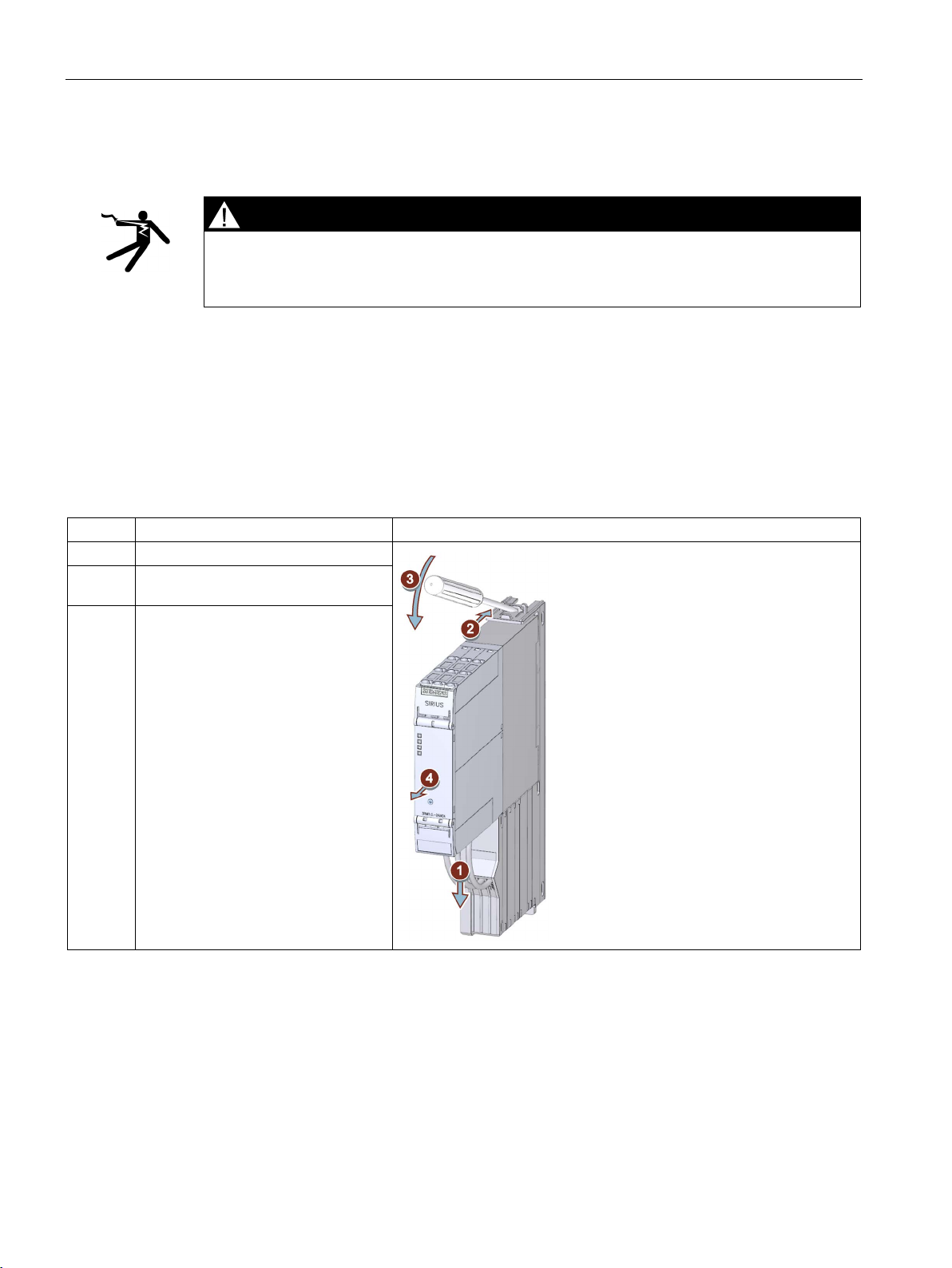
Mounting
5.6
Disassembling devices from a fuse module
DANGER
Hazardous voltage.
Will cause death or serious injury.
Requirements
Procedure
Step
Description
Figure
1
Detach the cables marked L1 to L3.
starter at the top.
5.6 Disassembling devices from a fuse module
Turn off and lock out all power supplying this device before working on this device.
● The fuse module has been removed from the adapter.
● The control circuit terminals have been removed or disconnected.
2 to 3 Use a screwdriver to unlatch the motor
4 Pull the 3RM1 motor starter out of the
fuse module.
SIRIUS 3RM1 motor starter
92 Manual, 06/2016, A5E0345285095020A/RS-AE/005
Page 93
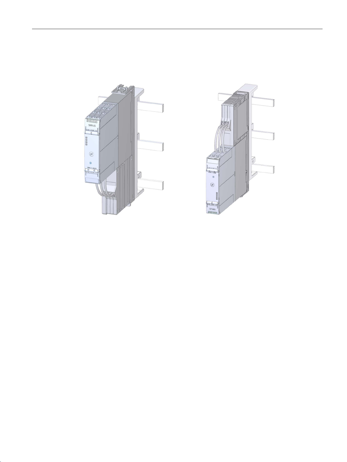
Mounting
5.7
Mounting the fuse module
Motor feeder at bottom
Motor feeder at top
Requirements
5.7 Mounting the fuse module
There are two possible mounting positions for the fuse module/motor starter assembly:
● The fuses have been fitted in the fuse module.
● The cover over the fuse compartment is closed.
● The motor starter has been installed and connected up.
SIRIUS 3RM1 motor starter
Manual, 06/2016, A5E0345285095020A/RS-AE/005
93
Page 94
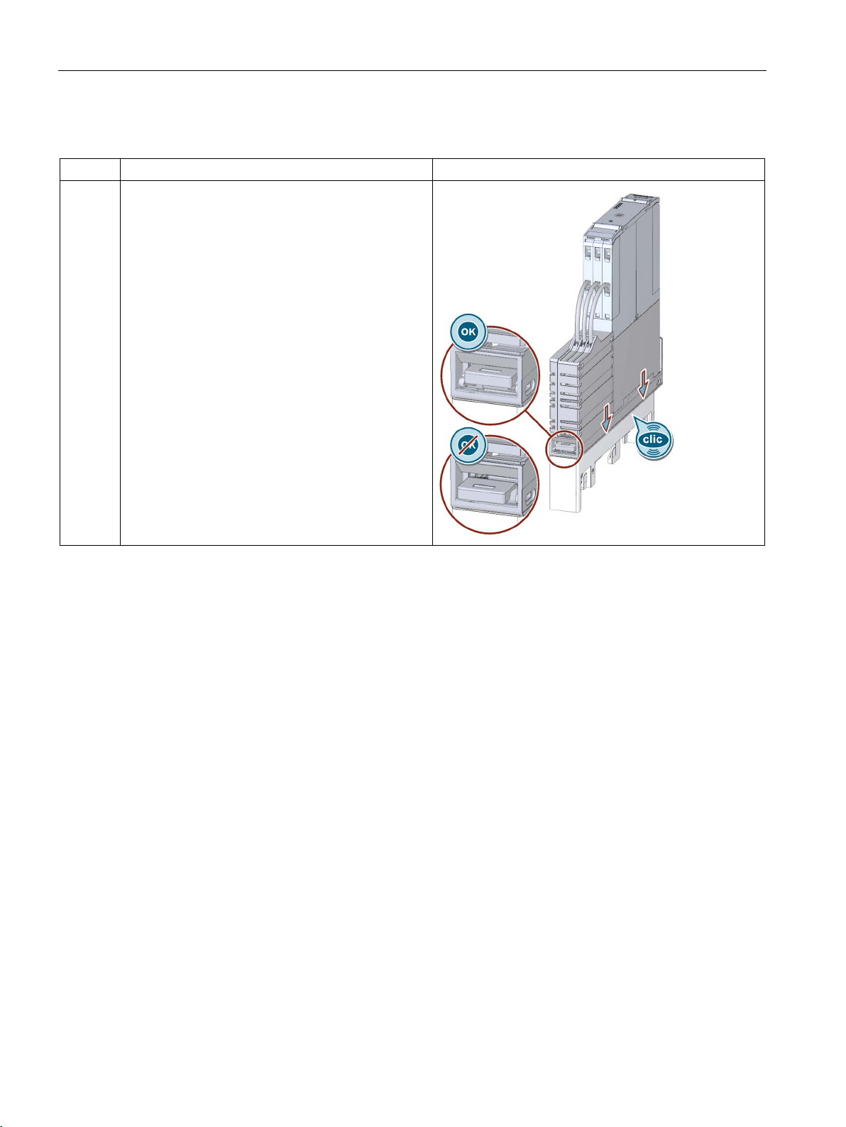
Mounting
Procedure
Step
Description
Figure
5.7 Mounting the fuse module
1
• Push the fuse module down onto the adapter until
it snaps into position.
• Check whether the fuse module is securely
engaged in the adapter.
• Check the lower narrow side of the fuse module
to make sure that the plastic lug is not protruding.
SIRIUS 3RM1 motor starter
94 Manual, 06/2016, A5E0345285095020A/RS-AE/005
Page 95
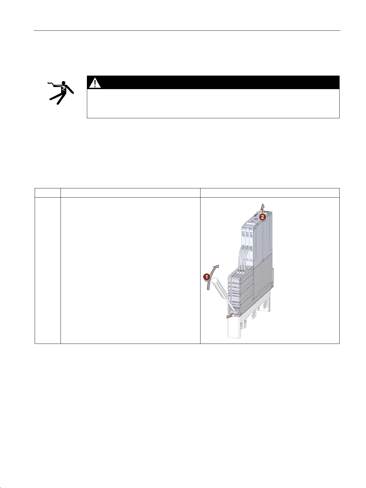
Mounting
5.8
Dismantling the fuse module
DANGER
Hazardous voltage.
Will cause death or serious injury.
Requirements
Procedure
Step
Description
Figure
5.8 Dismantling the fuse module
Turn off and lock out all power supplying this device before working on this device.
● The control circuit terminals have been removed or disconnected.
1 and 2
1. Use a screwdriver to press down the plastic lug on
the narrow side of the fuse module.
2. Pull the module upwards out of the adapter.
SIRIUS 3RM1 motor starter
Manual, 06/2016, A5E0345285095020A/RS-AE/005
95
Page 96
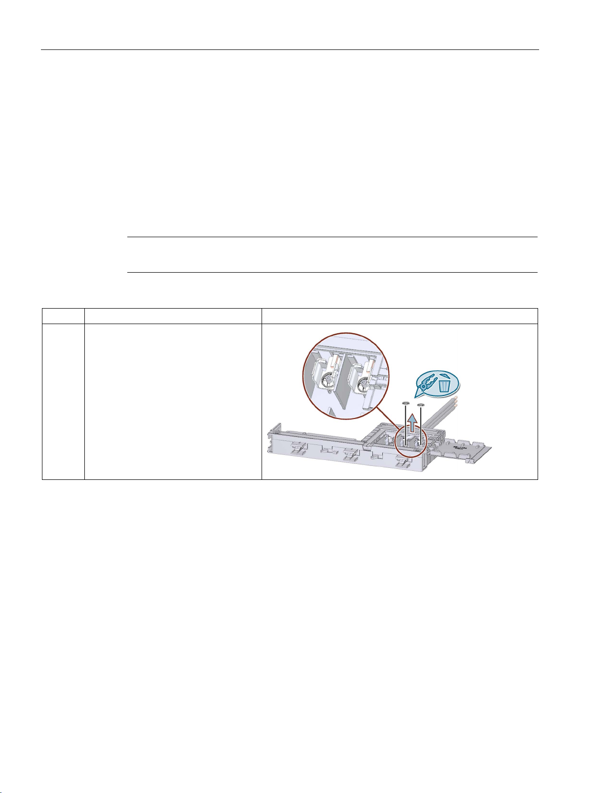
Mounting
5.9
Modifying the fuse module to a 1-pole connection
Requirements
Procedure
Note
Modify the fuse module before you install it.
Step
Description
Figure
5.9 Modifying the fuse module to a 1-pole connection
● The fuse module has been detached from the busbar system.
● The fuse compartment is open and the fuses removed from the compartment.
"Replacing the fuses in the 3RM19 fuse module (Page 137)"
1 Use a pair of pliers to remove the snap
rings at phases L2 and L3.
• Bottom
• Top
SIRIUS 3RM1 motor starter
96 Manual, 06/2016, A5E0345285095020A/RS-AE/005
Page 97
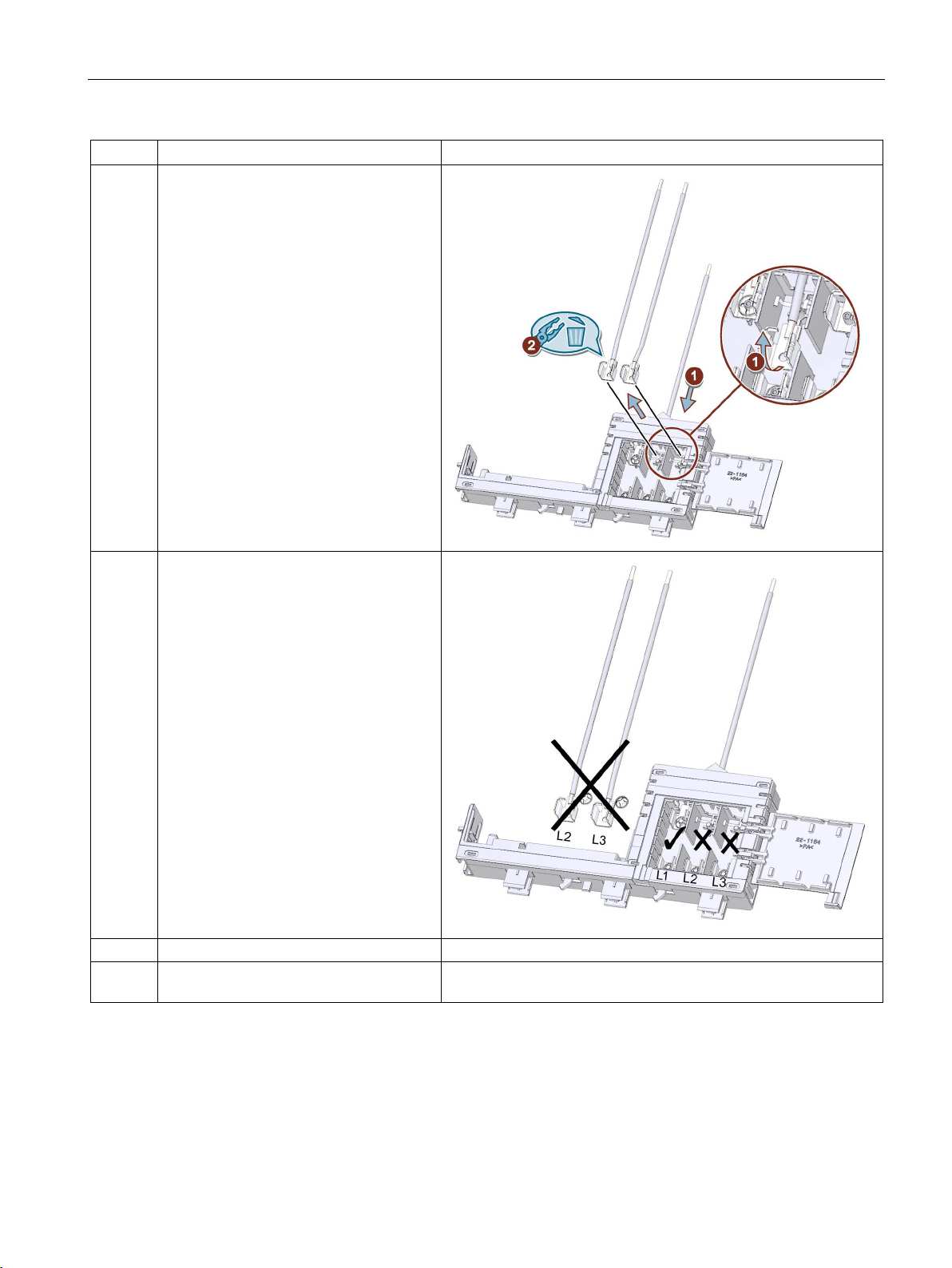
Mounting
Step
Description
Figure
4
Close the fuse compartment.
module.
5.9 Modifying the fuse module to a 1-pole connection
2
3 Insert the fuse into the fuse holder at
1. Pick up each of the fuse holders.
2. Pull each of the leads with the fuse
holder facing inwards out of the
housing.
phase 1.
5 Mount the motor starter on the fuse
SIRIUS 3RM1 motor starter
Manual, 06/2016, A5E0345285095020A/RS-AE/005
97
Page 98
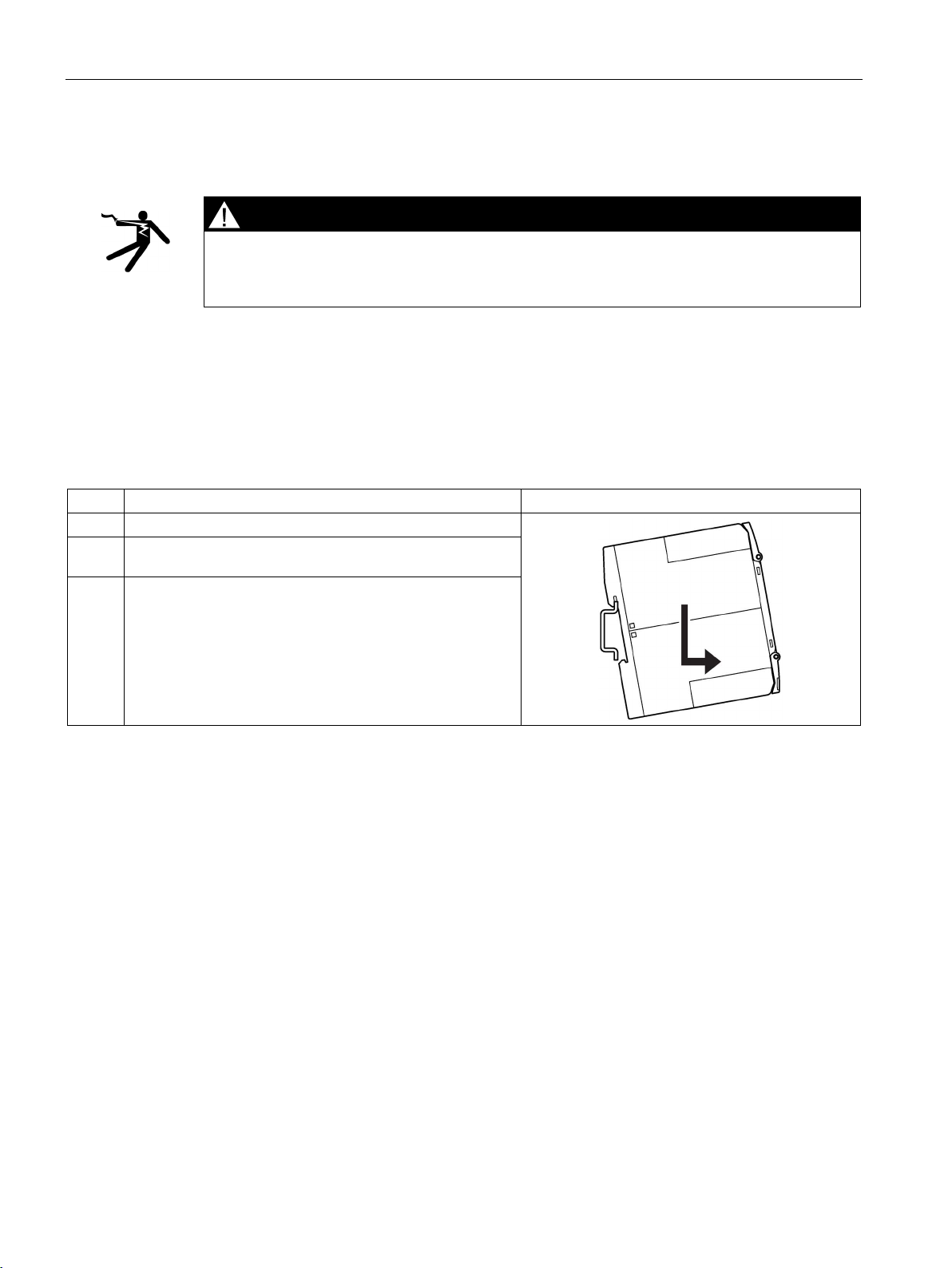
Mounting
5.10
Disassembling devices from a standard mounting rail
DANGER
Hazardous voltage.
Will cause death or serious injury.
Requirements
Procedure
Step
Operating instruction
Figure
1
Press the device downwards.
mounting rail.
5.10 Disassembling devices from a standard mounting rail
Turn off and lock out all power supplying this device before working on this device.
● The terminals have been removed or disconnected.
2 Pull the lower half of the device away from the standard
3 Lift the device from the upper edge of the standard
mounting rail.
SIRIUS 3RM1 motor starter
98 Manual, 06/2016, A5E0345285095020A/RS-AE/005
Page 99
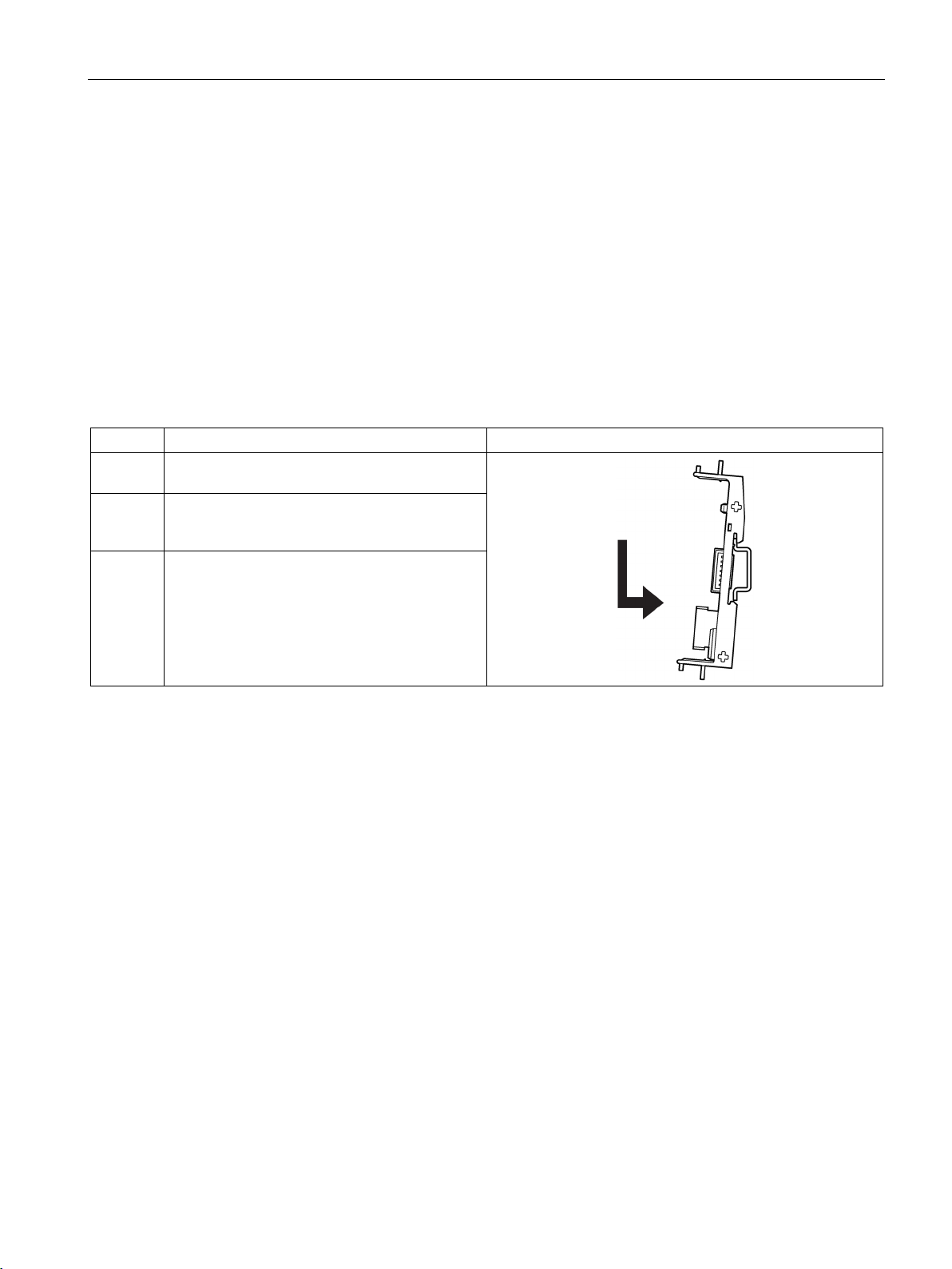
Mounting
5.11
Mounting the devices with device connectors on a standard
mounting rail
Requirements
Procedure
Step
Operating instruction
Figure
upper edge of the standard mounting rail.
engages.
5.11 Mounting the devices with device connectors on a standard mounting rail
● At the installation location, a horizontal 35 mm mounting rail in accordance with
DIN EN 60715 is properly secured
● Please observe the information about the mounting position in chapter "Mounting position
(Page 63)"
1 Place the back of the device connector on the
2 Press the lower half of the device connector
against the standard mounting rail until it
3 Repeat the procedure with all the required
device connectors.
SIRIUS 3RM1 motor starter
Manual, 06/2016, A5E0345285095020A/RS-AE/005
99
Page 100
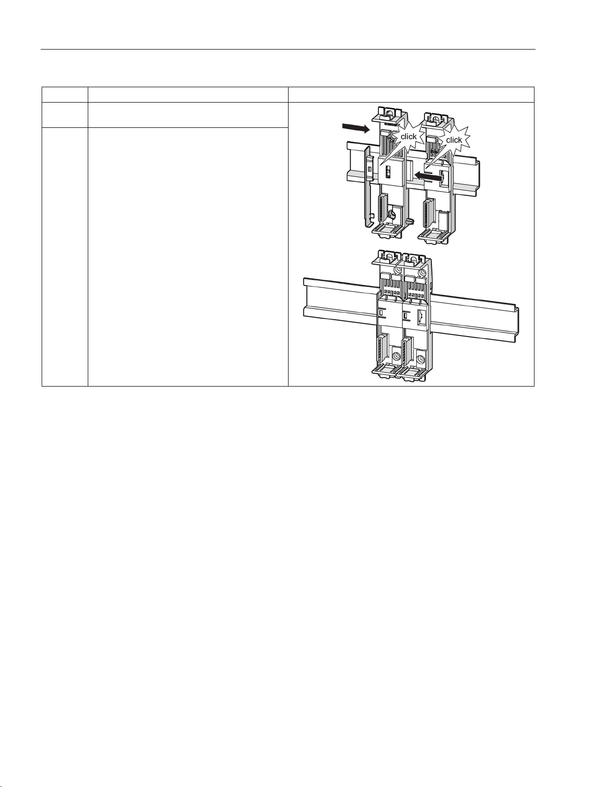
Mounting
Step
Operating instruction
Figure
engage.
5.11 Mounting the devices with device connectors on a standard mounting rail
4 Push the device connectors together until they
5 Mount the cover on the left on the first device
connector in the system configuration.
The cover is included in the scope of supply of
the device terminator.
SIRIUS 3RM1 motor starter
100 Manual, 06/2016, A5E0345285095020A/RS-AE/005
 Loading...